EP2925178B1 - Drehverschluss für einen schuh - Google Patents
Drehverschluss für einen schuh Download PDFInfo
- Publication number
- EP2925178B1 EP2925178B1 EP12801457.8A EP12801457A EP2925178B1 EP 2925178 B1 EP2925178 B1 EP 2925178B1 EP 12801457 A EP12801457 A EP 12801457A EP 2925178 B1 EP2925178 B1 EP 2925178B1
- Authority
- EP
- European Patent Office
- Prior art keywords
- intermediate carrier
- locking lever
- axis
- rotary closure
- housing
- Prior art date
- Legal status (The legal status is an assumption and is not a legal conclusion. Google has not performed a legal analysis and makes no representation as to the accuracy of the status listed.)
- Active
Links
Images

Classifications
-
- A—HUMAN NECESSITIES
- A43—FOOTWEAR
- A43C—FASTENINGS OR ATTACHMENTS OF FOOTWEAR; LACES IN GENERAL
- A43C11/00—Other fastenings specially adapted for shoes
- A43C11/16—Fastenings secured by wire, bolts, or the like
-
- A—HUMAN NECESSITIES
- A43—FOOTWEAR
- A43C—FASTENINGS OR ATTACHMENTS OF FOOTWEAR; LACES IN GENERAL
- A43C11/00—Other fastenings specially adapted for shoes
- A43C11/16—Fastenings secured by wire, bolts, or the like
- A43C11/165—Fastenings secured by wire, bolts, or the like characterised by a spool, reel or pulley for winding up cables, laces or straps by rotation
-
- A—HUMAN NECESSITIES
- A43—FOOTWEAR
- A43C—FASTENINGS OR ATTACHMENTS OF FOOTWEAR; LACES IN GENERAL
- A43C11/00—Other fastenings specially adapted for shoes
- A43C11/004—Fastenings fixed along the upper edges of the uppers
-
- A—HUMAN NECESSITIES
- A43—FOOTWEAR
- A43C—FASTENINGS OR ATTACHMENTS OF FOOTWEAR; LACES IN GENERAL
- A43C11/00—Other fastenings specially adapted for shoes
- A43C11/20—Fastenings with tightening devices mounted on the tongue
-
- Y—GENERAL TAGGING OF NEW TECHNOLOGICAL DEVELOPMENTS; GENERAL TAGGING OF CROSS-SECTIONAL TECHNOLOGIES SPANNING OVER SEVERAL SECTIONS OF THE IPC; TECHNICAL SUBJECTS COVERED BY FORMER USPC CROSS-REFERENCE ART COLLECTIONS [XRACs] AND DIGESTS
- Y10—TECHNICAL SUBJECTS COVERED BY FORMER USPC
- Y10T—TECHNICAL SUBJECTS COVERED BY FORMER US CLASSIFICATION
- Y10T24/00—Buckles, buttons, clasps, etc.
- Y10T24/21—Strap tighteners
- Y10T24/2183—Ski, boot, and shoe fasteners
-
- Y—GENERAL TAGGING OF NEW TECHNOLOGICAL DEVELOPMENTS; GENERAL TAGGING OF CROSS-SECTIONAL TECHNOLOGIES SPANNING OVER SEVERAL SECTIONS OF THE IPC; TECHNICAL SUBJECTS COVERED BY FORMER USPC CROSS-REFERENCE ART COLLECTIONS [XRACs] AND DIGESTS
- Y10—TECHNICAL SUBJECTS COVERED BY FORMER USPC
- Y10T—TECHNICAL SUBJECTS COVERED BY FORMER US CLASSIFICATION
- Y10T24/00—Buckles, buttons, clasps, etc.
- Y10T24/21—Strap tighteners
- Y10T24/2187—Rack and pinion and circular tighteners
-
- Y—GENERAL TAGGING OF NEW TECHNOLOGICAL DEVELOPMENTS; GENERAL TAGGING OF CROSS-SECTIONAL TECHNOLOGIES SPANNING OVER SEVERAL SECTIONS OF THE IPC; TECHNICAL SUBJECTS COVERED BY FORMER USPC CROSS-REFERENCE ART COLLECTIONS [XRACs] AND DIGESTS
- Y10—TECHNICAL SUBJECTS COVERED BY FORMER USPC
- Y10T—TECHNICAL SUBJECTS COVERED BY FORMER US CLASSIFICATION
- Y10T24/00—Buckles, buttons, clasps, etc.
- Y10T24/37—Drawstring, laced-fastener, or separate essential cooperating device therefor
- Y10T24/3703—Includes separate device for holding drawn portion of lacing
- Y10T24/3713—Includes separate device for holding drawn portion of lacing having relatively movable holding components or surfaces
-
- Y—GENERAL TAGGING OF NEW TECHNOLOGICAL DEVELOPMENTS; GENERAL TAGGING OF CROSS-SECTIONAL TECHNOLOGIES SPANNING OVER SEVERAL SECTIONS OF THE IPC; TECHNICAL SUBJECTS COVERED BY FORMER USPC CROSS-REFERENCE ART COLLECTIONS [XRACs] AND DIGESTS
- Y10—TECHNICAL SUBJECTS COVERED BY FORMER USPC
- Y10T—TECHNICAL SUBJECTS COVERED BY FORMER US CLASSIFICATION
- Y10T24/00—Buckles, buttons, clasps, etc.
- Y10T24/37—Drawstring, laced-fastener, or separate essential cooperating device therefor
- Y10T24/3703—Includes separate device for holding drawn portion of lacing
- Y10T24/3724—Includes separate device for holding drawn portion of lacing having lacing wound thereabout or wedged therein
Definitions
- the invention relates to a screw cap for a shoe, in particular for a sports shoe, comprising: a housing attachable to the shoe, a rotatably mounted in the housing about an axis tensioning roller on which when tightening the shoe, a tensioning element can be wound, and a rotary knob to the the axle is rotatably mounted on the housing to rotate the tension roller. Furthermore, the invention relates to a shoe with such a rotary closure.
- a generic rotary closure is for example from the DE 297 01 491 U1 known. Such a rotary closure should on the one hand at the tension of the clamping element (Schnürfaden or wire) by turning the knob with low torque and yet high clamping force allow the lacing of a shoe. On the other hand, a simple relaxation of the clamping element should be possible if the shoe is to be pulled out again.
- the knob was already pivotally mounted or hinged to the housing, wherein after the pivoting or flaps of the knob a Entrastung the tension roller takes place, so that the tensioned clamping element is de-energized.
- a push button can be operated to make the unlatching of the tension roller.
- planetary gears are used to reduce the rotational movement of the rotary knob to achieve said objectives.
- the invention has the object of providing a rotary closure of the generic type so that on the one hand a light yet strong tension of the clamping element is given when closing the rotary closure and on the other hand, a simple release or unlatching of the clamping element should be possible. At the same time a lightweight construction to be given and a cost-effective production can be realized with few components.
- the housing preferably has a cylindrical shape.
- the first locking toothing is preferably introduced on an inner circumference of the housing.
- This inner circumference is preferably cylindrical.
- the housing may be made of plastic, wherein the first locking toothing is formed in the material of the housing.
- the second locking toothing and the tensioning roller are preferably designed as an integral part, in particular as an injection-molded component.
- the axis of rotation for the relative to the housing movable or rotatably mounted parts is preferably formed by a bolt.
- a bolt screw
- the tensioning element is usually a tensioning wire.
- the two controls are preferably formed as formed on the knob pin-shaped projections, in particular as cylindrically shaped projections.
- the two controls can be arranged offset in the circumferential direction of the same diameter spaced from the axis lying.
- the intermediate carrier preferably has two pawls, which are arranged with respect to the axis of rotation diametrically opposite to the intermediate carrier.
- the at least one pawl can be arranged as radially to the axis of rotation resilient portion on the intermediate carrier.
- the pawl may continue to extend as a substantially straight, tongue-shaped portion substantially in the circumferential direction of the intermediate carrier.
- the intermediate carrier advantageously consists of a sheet metal part on which the pawls are formed from the material of the intermediate carrier.
- the locking lever is preferably made of metal.
- the locking lever can be arranged in the direction of the axis of rotation projecting bearing pin, which is mounted in a recess in the intermediate carrier.
- only a single locking lever is preferably arranged on or in the intermediate carrier.
- the knob can eccentrically at a peripheral point, d. H. spaced from the axis of a recess, in particular a circular recess, have; the intermediate carrier may have on its side facing the knob a mark, wherein the mark is visible through the recess when the knob with its second control in the second link portion of the locking lever and thus the locking lever is in the second pivot position.
- the marker is preferably formed as a color point.
- the invention relates to a shoe, in particular a sports shoe, with a rotary closure of the type described.
- the tensioner roller is provided with a detent (second detent toothing), which allows a rotation in one direction of rotation, but this prevents the engagement of the locking lever.
- the locking lever is rotatably mounted in the rotatably mounted about the central axis intermediate carrier (support member), namely about a central axis parallel to, but spaced therefrom pivot axis.
- the intermediate carrier can - for the purpose of tension of the cable - be rotated about the central axis, but only in the clamping direction, which is achieved by pawls (spring tongues), which are arranged radially outwardly resiliently on the intermediate carrier and engage in the first locking toothing (locking profile), the the inside of the housing edge is incorporated.
- the knob (cover), which is rotatably mounted about the central axis, has the two controls (driving cam).
- the first control engages when tensioning the cable (rotation in the direction of R1) on the intermediate carrier and rotates this together with locking lever in the closing direction. A reverse rotation of the tension roller is prevented in this case, because the locking portion (hook portion) of the locking lever engages in the second locking teeth of the tension roller, thus preventing the tension roller from rotating backwards.
- the second blocking element presses against the section-like section (second sliding section) of the blocking lever so that it is rotated about the pivot axis such that the locking section (FIG. Hook portion) is brought out of engagement with the second locking toothing (detent) of the tensioning roller; now The coiled cable can be pulled from the now freely rotatable tension pulley.
- the geometric design of the parts makes it possible with low torques on the knob, a high tensile stress in the clamping element is achieved when the shoe or the clamping element are tensioned.
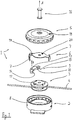
- a screw cap 1 can be seen, which can be attached, for example, on the instep of a shoe to serve to stoke the shoe; but other locations are possible, for. B. in the side area or in the heel area of the shoe.
- the rotary closure 1 has a cylindrical housing 2, which consists of plastic and is provided on an inner cylindrical surface with a first locking toothing 8.
- a bolt 16 eg in the form of a screw with end-side closure by a nut
- a central axis A is formed, by means of which various rotatable parts of the rotary closure 1 are mounted.
- a tension roller 3 is freely rotatably mounted in the housing 2.
- a tensioning cable or tensioning element 4 can be wound, in a known manner so that when winding the tightened shoe at the foot of the wearer is tensioned or laced.
- the tension roller 3 On the upper side of the tension roller 3, a second locking toothing 11 is formed.
- the tension roller 3 is also made of plastic, so that the locking toothing 11 is formed by the injection molding of the molded part.
- an intermediate carrier 6 Placed on the tension roller 3 and also mounted about the axis A is an intermediate carrier 6, which consists of a stamped and formed sheet metal part.
- the intermediate carrier 6 has two pawls 7 which are provided and designed to engage in the first ratchet teeth 8. Accordingly, the intermediate carrier 6 can rotate relative to the housing 2 only in one direction of rotation (namely in the direction of rotation R1, s. Fig. 2 ); the opposite rotation is prevented by the engaging in the first ratchet 8 pawls 7.
- a locking lever 9 made of metal (steel) is arranged between the tension roller 3 and the intermediate carrier 6, a locking lever 9 made of metal (steel) is arranged.
- the locking lever has a bearing pin 17, which fits into a recess 18 which is incorporated in the intermediate carrier 6.
- the rotary knob 5 is rotatably arranged about the axis A.
- the knob 5 has at its in Fig. 1 underneath underside two in the direction of the axis A and B protruding controls, namely a first control element 12 and a second control element 13.
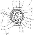
- a first control element 12 and a second control element 13 In the illustrations according to the Figures 2 and 3 is the Location of the two controls 12 and 13 to recognize. Both controls are - which is preferred - formed in the embodiment as a cylindrical in the direction of the axis A from the knob 5 projecting portions. They are provided alternatively cooperate with two slide sections 14 and 15 of the locking lever 9.
- a recess 19 is provided on the intermediate carrier 6, a color marking 20 (s. Fig. 1 ). About these elements can be made immediately visible to the user, whether the rotary closure in the unlatched position, ie the locking lever 9 in the second pivot position II, is. If the color marking 20 visible in the recess 19, the user knows that he has turned the knob 5 far enough in the second direction of rotation R2, so that the unlatching position of the rotary closure is reached.
Landscapes
- Footwear And Its Accessory, Manufacturing Method And Apparatuses (AREA)
- Devices For Conveying Motion By Means Of Endless Flexible Members (AREA)
- Prostheses (AREA)
Description
- Die Erfindung betrifft einen Drehverschluss für einen Schuh, insbesondere für einen Sportschuh, umfassend: ein am Schuh anbringbares Gehäuse, ein im Gehäuse drehbar um eine Achse gelagerte Spannrolle, auf der beim Schüren des Schuhs ein Spannelement aufgewickelt werden kann, und einen Drehknopf, der um die Achse drehbar am Gehäuse angeordnet ist, um die Spannrolle zu drehen. Des weiteren betrifft die Erfindung einen Schuh mit einem solchen Drehverschluss.
- Ein gattungsgemäßer Drehverschluss ist beispielsweise aus der
DE 297 01 491 U1 bekannt. Ein solcher Drehverschlusses soll einerseits bei der Spannung des Spannelements (Schnürfaden bzw. -draht) durch Drehen des Drehknopfs mit geringem Drehmoment und dennoch hoher Spannkraft das Schnüren eines Schuhs zulassen. Andererseits soll auch eine einfache Entspannung des Spannelements möglich sein, wenn der Schuh wieder ausgezogen werden soll. - Weitere wichtige Aspekte sind ein leichtes Gewicht des Drehverschlusses und eine kostengünstige Herstellung mit möglichst wenig Teilen.
- Es sind Drehverschlüsse mit aufwändigen Mechaniken bekannt geworden, um das Entspannen des Spannelements in einfacher Weise möglich zu machen, siehe
US 2011/0266384 A1 . - Beispielsweise wurde der Drehknopf schon schwenkbar bzw. klappbar am Gehäuse angeordnet, wobei nach den Schwenken bzw. Klappen des Drehknopfs eine Entrastung der Spannrolle erfolgt, so dass das gespannte Spannelement spannungslos wird. Bei anderen Lösungen kann ein Druckknopf betätigt werden, um das Entrasten der Spannrolle vorzunehmen. Bei verschiedenen Arten anderer Drehverschlüsse kommen Planetengetriebe zur Untersetzung der Drehbewegung des Drehknopfs zum Einsatz, um die besagten Ziele zu erreichen.
- Nachteilig ist bei den bekannten Systemen, dass die genannten Forderungen nicht problemlos zusammengeführt werden können. Drehverschlüsse, die die mechanischen Erfordernisse erfüllen, sind oft so komplex konzipiert, dass eine teure Herstellung mit relativ vielen Bauteilen gegeben ist.
- Der Erfindung liegt die Aufgabe zugrunde, einen Drehverschluss der gattungsgemäßen Art so fortzubilden, dass einerseits eine leichte und dennoch kräftige Spannung des Spannelements beim Verschließen des Drehverschlusses gegeben ist und andererseits ein einfaches Lösen bzw. Entrasten des Spannelements möglich sein soll. Gleichzeitig soll eine leichte Konstruktion gegeben sein und eine kostengünstige Herstellung mit wenigen Bauteilen realisiert werden.
- Die Lösung dieser Aufgabe durch die Erfindung ist dadurch gekennzeichnet, dass der Drehverschluss gemäß der eingangs genannten Art weiterhin aufweist:
- einen Zwischenträger, der um die Achse drehbar im Gehäuse angeordnet ist, wobei der Zwischenträger mindestens eine Sperrklinke aufweist, die in eine erste Sperrverzahnung eingreift, die am oder im Gehäuse angeordnet ist, so dass sich der Zwischenträger nur in eine Drehrichtung relativ zum Gehäuse drehen kann,
- mindestens einen im oder am Zwischenträger angeordneten und um eine zur Achse parallelen Achse schwenkbar im oder an Zwischenträger gelagerten Sperrhebel, wobei der Sperrhebel einen Sperrabschnitt aufweist, der ausgebildet ist, um in einer ersten Schwenkposition des Sperrhebels in eine zweite Sperrverzahnung einzugreifen, die an der Spannrolle angeordnet ist, und der weiter ausgebildet ist, um in einer zweiten Schwenkposition des Sperrhebels mit der zweiten Sperrverzahnung außer Eingriff zu gelangen,
- Das Gehäuse weist bevorzugt eine zylindrische Gestalt auf.
- Die erste Sperrverzahnung ist vorzugsweise an einem Innenumfang des Gehäuses eingebracht. Dieser Innenumfang ist dabei bevorzugt zylindrisch ausgebildet. Das Gehäuse kann dabei aus Kunststoff bestehen, wobei die erste Sperrverzahnung in das Material des Gehäuses eingeformt ist.
- Die zweite Sperrverzahnung und die Spannrolle sind bevorzugt als einstückiges Teil, insbesondere als spritzgegossenes Bauteil, ausgebildet.
- Die Drehachse für die relativ zum Gehäuse beweglichen bzw. drehbar gelagerten Teile wird bevorzugt durch einen Bolzen gebildet. Hier ist insbesondere an einen Schraubbolzen (Schraube) gedacht.
- Das Spannelement ist zumeist ein Spanndraht.
- Die beiden Steuerelemente sind bevorzugt als am Drehknopf angeformte stiftförmige Vorsprünge ausgebildet, insbesondere als zylindrisch ausgebildete Vorsprünge. Die beiden Steuerelemente können dabei auf demselben Durchmesser von der Achse beabstandet liegend in Umfangsrichtung versetzt angeordnet sein.
- Der Zwischenträger weist vorzugsweise zwei Sperrklinken auf, die bezüglich der Drehachse diametral gegenüberliegend am Zwischenträger angeordnet sind. Die mindestens eine Sperrklinke kann dabei als radial zur Drehachse federnder Abschnitt am Zwischenträger angeordnet sein. Die Sperrklinke kann sich weiterhin als im wesentlichen gerader, zungenförmiger Abschnitt im wesentlichen in Umfangsrichtung des Zwischenträgers erstrecken.
- Der Zwischenträger besteht aus Fertigungsgründen vorteilhaft aus einem Blechteil, an dem die Sperrklinken aus dem Material des Zwischenträgers ausgebildet sind.
- Der Sperrhebel besteht bevorzugt aus Metall.
- Am Sperrhebel kann ein in Richtung der Drehachse vorspringender Lagerbolzen angeordnet sein, der in einer Ausnehmung im Zwischenträger gelagert ist.
- Dabei ist bevorzugt nur ein einziger Sperrhebel am oder im Zwischenträger angeordnet.
- Der Drehknopf kann an einer Umfangsstelle exzentrisch, d. h. beabstandet von der Achse eine Ausnehmung, insbesondere eine kreisförmige Ausnehmung, aufweisen; der Zwischenträger kann an seiner dem Drehknopf zugewandten Seite eine Markierung aufweisen, wobei die Markierung durch die Ausnehmung sichtbar ist, wenn sich der Drehknopf mit seinem zweiten Steuerelement im zweiten Kulissenabschnitt des Sperrhebels und sich somit der Sperrhebel in der zweiten Schwenkposition befindet. Hiermit ist es möglich, die Positionierung des Drehknopfs zu erkennen, wenn der Drehverschluss in der entriegelten Stellung ist und das Spannelement (Spanndraht) folglich zum Ausziehen des Schuhs entspannt ist. Die Markierung ist dabei bevorzugt als Farbpunkt ausgebildet.
- Des weiteren betrifft die Erfindung einen Schuh insbesondere einen Sportschuh, mit einem Drehverschluss der beschriebenen Art.
- Hiernach weist also der vorgeschlagene Drehverschluss ein Gehäuse auf, in dem die Spannrolle (Spulrad) für das Spannelement (Kabel) drehbar gelagert ist, und zwar um die Zentralachse. Die Spannrolle ist mit einer Rastierung versehen (zweite Sperrverzahnung), die eine Drehung in einer Drehrichtung zulässt, diese beim Eingriff des Sperrhebels jedoch verhindert. Der Sperrhebel ist in dem um die Zentralachse drehbar gelagerten Zwischenträger (Trägerelement) drehbar gelagert, und zwar um eine zur Zentralachse parallele, aber von dieser beabstandeten Schwenkachse. Der Zwischenträger kann - zwecks Spannung des Kabels - um die Zentralachse gedreht werden, allerdings nur in Spannrichtung, was durch Sperrklinken (Federzungen) erreicht wird, die radial nach außen federnd am Zwischenträger angeordnet sind und in die erste Sperrverzahnung (Rastprofil) eingreifen, das an der Innenseite des Gehäuserandes eingearbeitet ist.
- Der Drehknopf (Deckel), der um die Zentralachse drehbar gelagert ist, hat die beiden Steuerelemente (Mitnehmernocken). Das erste Steuerelement greift beim Spannen des Kabels (Drehung in Richtung R1) am Zwischenträger an und dreht diesen samt Sperrhebel in Schließrichtung. Ein Zurückdrehen der Spannrolle wird hierbei verhindert, weil der Sperrabschnitt (Hakenabschnitt) des Sperrhebels in die zweite Sperrverzahnung der Spannrolle eingreift und so die Spannrolle am Rückwärtsdrehen hindert.
- Wird der Drehknopf (Deckel) in Richtung entgegen der Spannrichtung (Drehrichtung R2) gedreht, drückt das zweite Sperrelement (Mitnehmernocken) gegen den kulissenartig ausgebildeten Abschnitt (zweiter Kulissenabschnitt) des Sperrhebels, so dass dieser um die Schwenkachse so gedreht wird, dass der Sperrabschnitt (Hakenabschnitt) außer Eingriff mit der zweiten Sperrverzahnung (Rastierung) der Spannrolle gebracht wird; nun kann das aufgewickelte Kabel von der jetzt frei drehbaren Spannrolle gezogen werden.
- Vorteilhafter Weise ergibt sich ein einfacher Aufbau mit wenigen Teilen, was nicht nur die Herstellkosten des Drehverschlusses gering hält, sondern auch das Gewicht des Drehverschlusses minimiert.
- Die geometrische Auslegung der Teile, insbesondere der Spannrolle, ermöglicht es, dass mit geringen Drehmomenten am Drehknopf eine hohe Zugspannung im Spannelement erreicht wird, wenn der Schuh bzw. das Spannelement gespannt werden.
- Indes ist es durch Zurückdrehen des Drehknopfs entgegen der Spann-Drehrichtung möglich, einen Entrastungszustand herzustellen, in dem das Spannelement von der Spannrolle abgezogen werden kann.
- In der Zeichnung ist ein Ausführungsbeispiel der Erfindung dargestellt. Es zeigen:
- Fig. 1
- in Explosionsdarstellung einen Drehverschluss für einen Sportschuh,
- Fig. 2
- einen Schnitt durch den Drehverschluss, der senkrecht zur Drehachse des Drehverschlusses verläuft, wobei ein verriegelter Zustand des Drehverschlusses dargestellt ist, und
- Fig. 3
- den Schnitt gemäß
Fig. 2 , wobei ein entriegelter Zustand des Drehverschlusses dargestellt ist. - In den Figuren ist ein Drehverschluss 1 zu sehen, der beispielsweise auf dem Rist eines Schuhs befestigt werden kann, um zum Schüren des Schuhs zu dienen; aber auch andere Anbringungsorte sind möglich, z. B. im Seitenbereich oder im Fersenbereich des Schuhs.
- Der Drehverschluss 1 weist ein zylindrisches Gehäuse 2 auf, das aus Kunststoff besteht und an einer innenzylindrischen Fläche mit einer ersten Sperrverzahnung 8 versehen ist. Mittels eines Bolzens 16 (z. B. in Form einer Schraube mit endseitigem Verschluss durch eine Mutter) wird eine zentrale Achse A gebildet, mittels der verschiedene drehbare Teile des Drehverschlusses 1 gelagert sind.
- Zunächst ist eine Spannrolle 3 frei drehbar im Gehäuse 2 gelagert. Auf der Spannrolle 3 kann ein Spannkabel bzw. Spannelement 4 aufgewickelt werden, und zwar in bekannter Weise so, dass beim Aufwickeln der angezogene Schuh am Fuß des Trägers gespannt bzw. geschnürt wird.
- Auf der Oberseite der Spannrolle 3 ist eine zweite Sperrverzahnung 11 angeformt. Die Spannrolle 3 besteht ebenfalls aus Kunststoff, so dass die Sperrverzahnung 11 durch den Spritzgießvorgang des Formteils angeformt ist.
- Auf die Spannrolle 3 aufgesetzt und ebenfalls um die Achse A gelagert ist ein Zwischenträger 6, der aus einem gestanzten und umgeformten Blechteil besteht. Der Zwischenträger 6 weist zwei Sperrklinken 7 auf, die zum Eingriff in die erste Sperrverzahnung 8 vorgesehen und ausgebildet sind. Demgemäß kann der Zwischenträger 6 relativ zum Gehäuse 2 nur in eine Drehrichtung drehen (nämlich in die Drehrichtung R1, s.
Fig. 2 ); die entgegengesetzte Drehung wird durch die in die erste Sperrverzahnung 8 eingreifenden Sperrklinken 7 verhindert. - Zwischen der Spannrolle 3 und dem Zwischenträger 6 ist ein Sperrhebel 9 aus Metall (Stahl) angeordnet. Der Sperrhebel weist einen Lagerbolzen 17 auf, der in eine Ausnehmung 18 passt, die in den Zwischenträger 6 eingearbeitet ist.
- Daher kann der Sperrhebel 9 um eine Achse B, die parallel zur Achse A, von dieser aber beabstandet ist, relativ zum Zwischenträger 6 schwenken und namentlich zwei Schwenkpositionen einnehmen:
- In einer ersten Schwenkposition I (s.
Fig. 2 ) greift der Sperrhebel 9 mit einem hakenartigen Sperrabschnitt 10 in die zweite Sperrverzahnung 11 ein. In dieser Position kann die Spannrolle 3 nur in Spannrichtung R1 gedreht werden. Das auf ihr aufgewickelte Spannelement 4 kann allerdings nicht abgewickelt werden, so dass das Spannelement 4 unter Spannung gehalten wird. - In einer zweiten Schwenkposition II (s.
Fig. 3 ) ist der Sperrabschnitt 10 mit der zweiten Sperrverzahnung 11 außer Eingriff gebracht. Demgemäß kann jetzt die Spannrolle 3 um die Achse A frei drehen, so dass sich das aufgewickelte Spannelement 4 abwickeln kann. - Oberhalb des Zwischenträgers 6 ist der Drehknopf 5 um die Achse A drehbar angeordnet. Der Drehknopf 5 hat an seiner in
Fig. 1 nicht zu sehenden Unterseite zwei in Richtung der Achse A bzw. B hervorspringende Steuerelemente, nämlich ein erstes Steuerelement 12 und ein zweites Steuerelement 13. In den Darstellungen gemäß denFiguren 2 und3 ist die Lage der beiden Steuerelemente 12 und 13 zu erkennen. Beide Steuerelemente sind - was bevorzugt ist - im Ausführungsbeispiel als zylinderförmig in Richtung der Achse A aus dem Drehknopf 5 vorspringende Abschnitte ausgebildet. Sie sind dabei vorgesehen, alternativ mit zwei Kulissenabschnitten 14 und 15 des Sperrhebels 9 zusammenzuwirken. - Wir in
Fig. 2 gesehen werden kann, wird beim Spannen des Spannelements 4, d. h. beim Aufwickeln desselben auf die Spannrolle 3, der Drehknopf 5 in die erste Drehrichtung R1 gedreht. Das erste Steuerelement 12 wird durch die Drehung des Drehknopfs 5 in den ersten Kulissenabschnitt 14 gedrückt, weshalb der Sperrhebel 9 die erste Schwenkposition I einnimmt und folglich der Sperrabschnitt 10 in die zweite Sperrverzahnung 11 eingreift. - Bei der Drehung des Drehknopfs 5 in Richtung R1 wird also nicht nur ein Abwickeln des Spannelements 4 von der Spannrolle 3 verhindert. Vielmehr nimmt der Drehknopf 5 über das erste Steuerelement 12 den Zwischenträger 6 samt Sperrhebel 9 sowie (über den Sperrabschnitt 10) die Spannrolle 3 in Drehrichtung R1 mit, so dass das Spannelement 4 auf der Spannrolle 3 aufgewickelt und die Spannrolle 3 im Übrigen am Zurückdrehen gehindert wird (besagtes Zurückdrehen wird durch die Sperrklinken 7 am Zwischenträger 6 verhindert).
- Bei der Drehung des Drehknopfs 5 in die entgegengesetzte Drehrichtung R2 indes wird - wie es
Fig. 3 illustriert - das zweite Steuerelement 13 in den zweiten Kulissenabschnitt 15 gedrückt, was den Sperrhebel 9 in die zweite Schwenkposition II bringt. Der Sperrabschnitt 10 tritt aus dem Eingriff mit der zweiten Sperrverzahnung 11 aus, so dass die Spannrolle 3 jetzt frei drehbar ist und das aufgewickelte Spannelement 4 abgezogen bzw. abgespult werden kann. - Im Drehknopf 5 ist eine Ausnehmung 19 vorgesehen, am Zwischenträger 6 eine farbliche Markierung 20 (s.
Fig. 1 ). Über diese Elemente kann für den Benutzer sofort sichtbar gemacht werden, ob der Drehverschluss in der Entrastposition, d. h. der Sperrhebel 9 in der zweiten Schwenkposition II, ist. Wird die Farbmarkierung 20 in der Ausnehmung 19 sichtbar, weiß der Anwender, dass er den Drehknopf 5 weit genug in die zweite Drehrichtung R2 zurückgedreht hat, so dass die Entrastposition des Drehverschlusses erreicht ist. -
- 1
- Drehverschluss
- 2
- Gehäuse
- 3
- Spannrolle
- 4
- Spannelement
- 5
- Drehknopf
- 6
- Zwischenträger
- 7
- Sperrklinke
- 8
- erste Sperrverzahnung
- 9
- Sperrhebel
- 10
- Sperrabschnitt
- 11
- zweite Sperrverzahnung
- 12
- erstes Steuerelement
- 13
- zweites Steuerelement
- 14
- erster Kulissenabschnitt
- 15
- zweiter Kulissenabschnitt
- 16
- Bolzen
- 17
- Lagerbolzen
- 18
- Ausnehmung (Bohrung)
- 19
- Ausnehmung
- 20
- Markierung
- A
- Achse
- B
- Achse
- I
- erste Schwenkposition
- II
- zweite Schwenkposition
- R1
- erste Drehrichtung
- R2
- zweite Drehrichtung
Claims (15)
- Drehverschluss (1) für einen Schuh, insbesondere für einen Sportschuh, umfassend:- ein am Schuh anbringbares Gehäuse (2),- ein im Gehäuse (2) drehbar um eine Achse (A) gelagerte Spannrolle (3), auf der beim Schnüren des Schuhs ein Spannelement (4) aufgewickelt werden kann, und- einen Drehknopf (5), der um die Achse (A) drehbar am Gehäuse (2) angeordnet ist, um die Spannrolle (3) zu drehen,dadurch gekennzeichnet,
dass der Drehverschluss (1) weiterhin aufweist:- einen Zwischenträger (6), der um die Achse (A) drehbar im Gehäuse (2) angeordnet ist, wobei der Zwischenträger (6) mindestens eine Sperrklinke (7) aufweist, die in eine erste Sperrverzahnung (8) eingreift, die am oder im Gehäuse (2) angeordnet ist, so dass sich der Zwischenträger (6) nur in eine Drehrichtung relativ zum Gehäuse (2) drehen kann,- mindestens einen im oder am Zwischenträger (6) angeordneten und um eine zur Achse (A) parallelen Achse (B) schwenkbar im oder an Zwischenträger (6) gelagerten Sperrhebel (9), wobei der Sperrhebel (9) einen Sperrabschnitt (10) aufweist, der ausgebildet ist, um in einer ersten Schwenkposition (I) des Sperrhebels (9) in eine zweite Sperrverzahnung (11) einzugreifen, die an der Spannrolle (3) angeordnet ist, und der weiter ausgebildet ist, um in einer zweiten Schwenkposition (II) des Sperrhebels (9) mit der zweiten Sperrverzahnung (11) außer Eingriff zu gelangen,wobei am Drehknopf (5) ein erstes Steuerelement (12) und ein zweites Steuerelement (13) angeordnet sind, wobei das erste Steuerelement (12) bei Drehung des Drehknopfs (5) in eine erste Drehrichtung (R1) in einen ersten Kulissenabschnitt (14) des Sperrhebels (9) eingreifen kann, um den Sperrhebel (9) in die erste Schwenkposition (I) zu bewegen und den Zwischenträger (6) samt Spannrolle (3) zu drehen, und wobei das zweite Steuerelement (13) bei Drehung des Drehknopfs (5) in eine zur ersten Drehrichtung (R1) entgegengesetzten zweiten Drehrichtung (R2) in einen zweiten Kulissenabschnitt (15) des Sperrhebels (9) eingreifen kann, um den Sperrhebel (9) in die zweite Schwenkposition (II) zu bewegen. - Drehverschluss nach Anspruch 1, dadurch gekennzeichnet, dass das Gehäuse (2) eine zylindrische Gestalt aufweist.
- Drehverschluss nach Anspruch 1 oder 2, dadurch gekennzeichnet, dass die erste Sperrverzahnung (8) an einem Innenumfang des Gehäuses (2) eingebracht ist.
- Drehverschluss nach Anspruch 3, dadurch gekennzeichnet, dass das Gehäuse (2) aus Kunststoff besteht, wobei die erste Sperrverzahnung (8) in das Material des Gehäuses (2) eingeformt ist.
- Drehverschluss nach einem der Ansprüche 1 bis 4, dadurch gekennzeichnet, dass die zweite Sperrverzahnung (11) und die Spannrolle (3) als einstückiges Teil, insbesondere als spritzgegossenes Bauteil, ausgebildet sind.
- Drehverschluss nach einem der Ansprüche 1 bis 5, dadurch gekennzeichnet, dass die Drehachse (A) für die relativ zum Gehäuse (2) beweglichen Teile durch einen Bolzen (16), insbesondere durch einen Schraubbolzen, gebildet wird.
- Drehverschluss nach einem der Ansprüche 1 bis 6, dadurch gekennzeichnet, dass die beiden Steuerelemente (12, 13) als am Drehknopf (5) angeformte stiftförmige Vorsprünge, vorzugsweise als zylindrisch ausgebildete Vorsprünge, ausgebildet sind.
- Drehverschluss nach Anspruch 7, dadurch gekennzeichnet, dass die beiden Steuerelemente (12, 13) auf dem selben Durchmesser von der Achse (A) beabstandet liegend in Umfangsrichtung versetzt angeordnet sind.
- Drehverschluss nach einem der Ansprüche 1 bis 8, dadurch gekennzeichnet, dass der Zwischenträger (6) zwei Sperrklinken (7) aufweist, die bezüglich der Drehachse (A) diametral gegenüberliegend am Zwischenträger (6) angeordnet sind.
- Drehverschluss nach einem der Ansprüche 1 bis 9, dadurch gekennzeichnet, dass die mindestens eine Sperrklinke (7) als radial zur Drehachse (A) federnder Abschnitt am Zwischenträger (6) angeordnet ist, wobei sich die Sperrklinke (7) vorzugsweise als im wesentlichen gerader, zungenförmiger Abschnitt im wesentlichen in Umfangsrichtung des Zwischenträgers (6) erstreckt.
- Drehverschluss nach einem der Ansprüche 1 bis 10, dadurch gekennzeichnet, dass der Zwischenträger (6) aus einem Blechteil besteht, an dem die Sperrklinken (7) aus dem Material des Zwischenträgers (6) ausgebildet sind.
- Drehverschluss nach einem der Ansprüche 1 bis 11, dadurch gekennzeichnet, dass am Sperrhebel (9) ein in Richtung der Drehachse (A) vorspringender Lagerbolzen (17) angeordnet ist, der in einer Ausnehmung (18) im Zwischenträger (6) gelagert ist.
- Drehverschluss nach einem der Ansprüche 1 bis 12, dadurch gekennzeichnet, dass ein einziger Sperrhebel (9) am oder im Zwischenträger (6) angeordnet ist.
- Drehverschluss nach einem der Ansprüche 1 bis 13, dadurch gekennzeichnet, dass der Drehknopf (5) an einer Umfangsstelle exzentrisch von der Achse (A) eine Ausnehmung (19), insbesondere eine kreisförmige Ausnehmung, aufweist, und dass der Zwischenträger (6) an seiner dem Drehknopf (5) zugewandten Seite eine Markierung (20), vorzugsweise einen Farbpunkt, aufweist, wobei die Markierung (20) durch die Ausnehmung (19) sichtbar ist, wenn sich der Drehknopf (5) mit seinem zweiten Steuerelement (13) im zweiten Kulissenabschnitt (15) des Sperrhebels (9) und sich somit der Sperrhebel (9) in der zweiten Schwenkposition (II) befindet.
- Schuh, insbesondere Sportschuh, mit einem Drehverschluss nach einem der Ansprüche 1 bis 14.
Priority Applications (2)
| Application Number | Priority Date | Filing Date | Title |
|---|---|---|---|
| HUE12801457A HUE033756T2 (en) | 2012-11-30 | 2012-11-30 | Rotary shoe for shoe |
| PL12801457T PL2925178T3 (pl) | 2012-11-30 | 2012-11-30 | Zamknięcie obrotowe do buta |
Applications Claiming Priority (1)
| Application Number | Priority Date | Filing Date | Title |
|---|---|---|---|
| PCT/EP2012/004984 WO2014082652A1 (de) | 2012-11-30 | 2012-11-30 | Drehverschluss für einen schuh |
Publications (2)
| Publication Number | Publication Date |
|---|---|
| EP2925178A1 EP2925178A1 (de) | 2015-10-07 |
| EP2925178B1 true EP2925178B1 (de) | 2017-01-11 |
Family
ID=47358084
Family Applications (1)
| Application Number | Title | Priority Date | Filing Date |
|---|---|---|---|
| EP12801457.8A Active EP2925178B1 (de) | 2012-11-30 | 2012-11-30 | Drehverschluss für einen schuh |
Country Status (16)
| Country | Link |
|---|---|
| US (1) | US9072341B2 (de) |
| EP (1) | EP2925178B1 (de) |
| JP (1) | JP5905644B2 (de) |
| KR (1) | KR101660152B1 (de) |
| CN (1) | CN104394730B (de) |
| AU (1) | AU2012395552B2 (de) |
| BR (1) | BR112014028397B1 (de) |
| CA (1) | CA2874232C (de) |
| ES (1) | ES2621836T3 (de) |
| HU (1) | HUE033756T2 (de) |
| IN (1) | IN2014DN10107A (de) |
| MX (1) | MX344775B (de) |
| PL (1) | PL2925178T3 (de) |
| PT (1) | PT2925178T (de) |
| RU (1) | RU2597539C2 (de) |
| WO (1) | WO2014082652A1 (de) |
Families Citing this family (83)
| Publication number | Priority date | Publication date | Assignee | Title |
|---|---|---|---|---|
| EP1814417B1 (de) | 2004-10-29 | 2014-04-16 | Boa Technology, Inc. | Verschlusssystem auf Spulengrundlage |
| KR101688997B1 (ko) | 2008-11-21 | 2016-12-22 | 보아 테크놀러지, 인크. | 릴 기반 끈 조임 시스템 |
| US9375053B2 (en) | 2012-03-15 | 2016-06-28 | Boa Technology, Inc. | Tightening mechanisms and applications including the same |
| US10070695B2 (en) | 2010-04-30 | 2018-09-11 | Boa Technology Inc. | Tightening mechanisms and applications including the same |
| KR101107372B1 (ko) * | 2011-05-30 | 2012-01-19 | 소윤서 | 줄 길이 조절장치 |
| US9101181B2 (en) | 2011-10-13 | 2015-08-11 | Boa Technology Inc. | Reel-based lacing system |
| DE112013005273B4 (de) | 2012-11-02 | 2017-08-24 | Boa Technology, Inc. | Kupplungsteile für Verschlussvorrichtungen und -systeme |
| EP2916680B1 (de) | 2012-11-06 | 2018-12-26 | Boa Technology Inc. | Vorrichtungen und verfahren zur einstellung der passform von schuhen |
| US9439477B2 (en) | 2013-01-28 | 2016-09-13 | Boa Technology Inc. | Lace fixation assembly and system |
| US10251451B2 (en) | 2013-03-05 | 2019-04-09 | Boa Technology Inc. | Closure devices including incremental release mechanisms and methods therefor |
| EP2964048B1 (de) | 2013-03-05 | 2019-08-28 | Boa Technology Inc. | Systeme und vorrichtungen zum automatischen schliessen von medizinischen vorrichtungen |
| KR20260030757A (ko) * | 2013-04-01 | 2026-03-06 | 보아 테크놀러지, 인크. | 릴 기반의 폐쇄 시스템을 포함하도록 신발류를 개장하기 위한 방법 및 장치 |
| ITTV20130045A1 (it) * | 2013-04-09 | 2014-10-10 | Northwave Srl | Dispositivo di serraggio |
| EP4721617A2 (de) | 2013-06-05 | 2026-04-08 | Boa Technology, Inc. | Komponenten und verfahren für eine integrierte verschlussvorrichtung |
| US10076160B2 (en) | 2013-06-05 | 2018-09-18 | Boa Technology Inc. | Integrated closure device components and methods |
| JP6105404B2 (ja) * | 2013-06-18 | 2017-03-29 | 株式会社ジャパーナ | 靴紐巻取用リール |
| JP6087219B2 (ja) * | 2013-06-18 | 2017-03-01 | 株式会社ジャパーナ | 靴紐巻取装置 |
| DE112014003135B4 (de) | 2013-07-02 | 2020-12-24 | Boa Technology Inc. | Rolle zur verwendung mit einem verschnürungssystem zum festziehen eines gegenstandes sowie vorrichtungen hierzu und verfahren zum zusammenbauen einer vorrichtung zum festziehen eines gegenstandes |
| WO2015006616A1 (en) | 2013-07-10 | 2015-01-15 | Boa Technology Inc. | Closure devices including incremental release mechanisms and methods therefor |
| WO2015035257A2 (en) | 2013-09-05 | 2015-03-12 | Boa Technology Inc. | Alternative lacing guides for tightening mechanisms and methods therefor |
| KR102738961B1 (ko) | 2013-09-13 | 2024-12-06 | 보아 테크놀러지, 인크. | 릴 기반 폐쇄 장치 및 그에 따른 방법 |
| KR101895140B1 (ko) | 2013-11-18 | 2018-09-04 | 보아 테크놀러지, 인크. | 보철 및 장구의 자동 폐쇄를 제공하기 위한 방법 및 장치 |
| USD835976S1 (en) | 2014-01-16 | 2018-12-18 | Boa Technology Inc. | Coupling member |
| TWI561453B (en) * | 2014-02-17 | 2016-12-11 | Chin Chu Chen | A device for tightening and loosening a lace |
| FR3023455B1 (fr) * | 2014-07-08 | 2016-08-26 | Mavic Sas | Dispositif d'enroulement et de blocage a cliquet d'un lacet de serrage |
| US20160058127A1 (en) | 2014-08-28 | 2016-03-03 | Boa Technology Inc. | Devices and methods for enhancing the fit of boots and other footwear |
| WO2016057697A1 (en) | 2014-10-07 | 2016-04-14 | Boa Technology Inc. | A tension adjustment mechanism and a method for adjusting the fit of a shoe |
| US10264852B2 (en) | 2015-01-14 | 2019-04-23 | Sug Whan Kim | String winding and unwinding apparatus |
| USD835898S1 (en) | 2015-01-16 | 2018-12-18 | Boa Technology Inc. | Footwear lace tightening reel stabilizer |
| KR101737885B1 (ko) | 2015-07-07 | 2017-05-29 | 박지훈 | 다이얼 방식의 신발 끈 조임장치 |
| CN105159393B (zh) * | 2015-09-24 | 2017-06-20 | 惠州市富池精工股份有限公司 | 一种单向止转的旋钮 |
| US11033079B2 (en) | 2015-10-07 | 2021-06-15 | Puma SE | Article of footwear having an automatic lacing system |
| US11103030B2 (en) | 2015-10-07 | 2021-08-31 | Puma SE | Article of footwear having an automatic lacing system |
| US11185130B2 (en) | 2015-10-07 | 2021-11-30 | Puma SE | Article of footwear having an automatic lacing system |
| WO2017059875A1 (de) | 2015-10-07 | 2017-04-13 | Puma SE | Schuh, insbesondere sportschuh |
| EP3358981B1 (de) * | 2015-10-07 | 2019-07-17 | Puma Se | Schuh, insbesondere sportschuh |
| US10004297B2 (en) | 2015-10-15 | 2018-06-26 | Boa Technology Inc. | Lacing configurations for footwear |
| EP3383211B1 (de) | 2015-12-02 | 2019-09-25 | Puma Se | Verfahren zum schnüren eines schuhs, insbesondere eines sportschuhs |
| US20190116917A1 (en) * | 2016-03-15 | 2019-04-25 | Mizuno Corporation | Footwear Having An Adjustable Heel Mechanism |
| US10834999B2 (en) * | 2016-05-18 | 2020-11-17 | Nike, Inc. | Article of footwear with a pulley system |
| US10624423B2 (en) | 2016-05-18 | 2020-04-21 | Nike, Inc. | Article of footwear with a pulley system having a guide portion |
| US11026472B2 (en) | 2016-07-22 | 2021-06-08 | Nike, Inc. | Dynamic lacing system |
| KR20250020493A (ko) | 2016-08-02 | 2025-02-11 | 보아 테크놀러지, 인크. | 신발끈 결속 시스템의 인장 부재 가이드 |
| US10149035B2 (en) * | 2016-08-31 | 2018-12-04 | Bluecom Co., Ltd. | Automatic winding module of wire for bluetooth headset with improved wear resistance function of rotation axis |
| US10918165B2 (en) | 2016-11-11 | 2021-02-16 | Chin-Chu Chen | Fastening device and lace assembling method thereof |
| US11607014B2 (en) | 2016-11-11 | 2023-03-21 | Chin-Chu Chen | Fastening device and lace assembling method |
| US11751634B2 (en) | 2016-11-11 | 2023-09-12 | Chin-Chu Chen | Fastening device and lace assembling method |
| JP7295017B2 (ja) | 2016-11-22 | 2023-06-20 | プーマ エス イー | 着用者に対して衣類を装着するもしくは取り去る、または人が持ち運ぶ荷物を閉じる、装着する、開放する、もしくは取り去るための方法 |
| EP3544460B1 (de) | 2016-11-22 | 2025-01-08 | Puma Se | Verfahren zum schnüren eines schuhs, insbesondere eines sportschuhs, und schuh, insbesondere sportschuh |
| KR102822775B1 (ko) | 2016-12-09 | 2025-06-20 | 보아 테크놀러지, 인크. | 릴 기반의 폐쇄 시스템 |
| US10543630B2 (en) | 2017-02-27 | 2020-01-28 | Boa Technology Inc. | Reel based closure system employing a friction based tension mechanism |
| DE102018201019A1 (de) | 2017-02-28 | 2018-08-30 | Fidlock Gmbh | Verschlussvorrichtung mit einem Wickelelement |
| US11357279B2 (en) | 2017-05-09 | 2022-06-14 | Boa Technology Inc. | Closure components for a helmet layer and methods for installing same |
| US10772384B2 (en) | 2017-07-18 | 2020-09-15 | Boa Technology Inc. | System and methods for minimizing dynamic lace movement |
| US12396520B2 (en) | 2017-07-18 | 2025-08-26 | Boa Technology Inc. | Configurations for footwear employing reel based closure systems |
| DE102018201021A1 (de) * | 2017-11-14 | 2019-05-16 | Fidlock Gmbh | Verschlussvorrichtung mit einem Wickelelement |
| CN108371370B (zh) * | 2018-02-09 | 2021-08-20 | 深圳市爱康伟达智能医疗科技有限公司 | 一种新型的系带系统及其使用方法 |
| DE102018202390A1 (de) | 2018-02-16 | 2019-08-22 | Bayerische Motoren Werke Aktiengesellschaft | Kraftfahrzeugsitz, hiermit ausgestattetes Kraftfahrzeug sowie Verfahren zum Einstellen einer Bezugsspannung des Kraftfahrzeugsitzes |
| US11633018B2 (en) | 2018-10-29 | 2023-04-25 | Pride Manufacturing Company, Llc | Latching system for a rotary closure |
| USD907992S1 (en) * | 2018-11-30 | 2021-01-19 | Sug Whan Kim | String fastener |
| USD906657S1 (en) | 2019-01-30 | 2021-01-05 | Puma SE | Shoe tensioning device |
| USD889805S1 (en) | 2019-01-30 | 2020-07-14 | Puma SE | Shoe |
| USD899053S1 (en) | 2019-01-30 | 2020-10-20 | Puma SE | Shoe |
| EP4678055A3 (de) | 2019-02-01 | 2026-04-15 | Boa Technology, Inc. | Auf rollen basierende verschlussvorrichtungen zum festziehen eines skischuhes |
| KR102189249B1 (ko) * | 2019-04-10 | 2020-12-09 | 하민우 | 와이어 조임장치 |
| JP7454267B2 (ja) | 2019-05-01 | 2024-03-22 | ボア テクノロジー,インコーポレイテッド | リール式クロージャーシステム |
| EP3962315A1 (de) * | 2019-05-03 | 2022-03-09 | Pride Manufacturing Company, LLC | Systeme und verfahren für einen drehverschluss |
| WO2020247645A1 (en) | 2019-06-05 | 2020-12-10 | Hurley Garrett Ray | Adjustable closure devices with handle and locking mechanisms |
| DE202019105576U1 (de) * | 2019-10-10 | 2019-10-22 | Roland Jungkind | Drehverschluss mit Spannelement |
| US11484089B2 (en) | 2019-10-21 | 2022-11-01 | Puma SE | Article of footwear having an automatic lacing system with integrated sound damping |
| CN112993685B (zh) * | 2020-11-24 | 2022-09-27 | 环旭(深圳)电子科创有限公司 | 收线装置 |
| CN113267568A (zh) * | 2021-04-30 | 2021-08-17 | 西安热工研究院有限公司 | 一种超声检测用探头线缆整理回收装置 |
| CN115500581B (zh) * | 2021-06-23 | 2025-07-25 | 东莞市旋系智能科技有限公司 | 一种快速系带器 |
| EP4144250A4 (de) * | 2021-07-19 | 2023-03-08 | Shishi Senke Intelligent Technology Co., Ltd. | Rotierende zug-druck-seilaufroller und schuhe |
| US12171306B2 (en) | 2021-11-16 | 2024-12-24 | Puma SE | Article of footwear having an automatic lacing system |
| WO2023147436A1 (en) * | 2022-01-26 | 2023-08-03 | Pride Manufacturing Company, Llc | An improved rotary closure featuring a cam-actuated spool-release mechanism |
| US11717076B1 (en) | 2022-04-26 | 2023-08-08 | Hand Held Products, Inc. | Strap assembly for a wearable mobile device and method of using the same |
| US11647813B1 (en) * | 2022-06-01 | 2023-05-16 | Chunming Rao | Quick lacing system |
| TW202406824A (zh) * | 2022-08-01 | 2024-02-16 | 蔡志信 | 緊固裝置 |
| JP2025534079A (ja) * | 2022-10-24 | 2025-10-09 | プーマ エス イー | クロージャーシステムを有する履物に係る物品 |
| CN116195807A (zh) * | 2022-12-05 | 2023-06-02 | 东莞市壹创信息科技有限公司 | 擒放旋转控制离合器 |
| US12599121B2 (en) * | 2023-03-17 | 2026-04-14 | Juka Innovations Corporation | Fishing line to lure connector |
| WO2025042440A1 (en) | 2023-08-23 | 2025-02-27 | Pride Manufacturing Company, Llc D/B/A Gathr Outdoors | Systems and methods for a rotary closure |
Family Cites Families (31)
| Publication number | Priority date | Publication date | Assignee | Title |
|---|---|---|---|---|
| SU15359A1 (ru) * | 1928-05-19 | 1930-05-31 | Э.В. Коллер | Зажим дл шнурка |
| US2926406A (en) * | 1959-03-27 | 1960-03-01 | Edwards George Zahnor | Length adjustment mechanism |
| IT1193578B (it) * | 1981-01-28 | 1988-07-08 | Nordica Spa | Dispositivo di chiusura particolarmente per scarponi da sci |
| FR2569087B1 (fr) * | 1984-08-17 | 1987-01-09 | Salomon Sa | Chaussure de ski |
| DE3913018A1 (de) * | 1989-04-20 | 1990-10-25 | Weinmann & Co Kg | Drehverschluss fuer einen sportschuh, insbesondere einen skischuh |
| US5177882A (en) * | 1989-06-03 | 1993-01-12 | Puma Ag Rudolf Dassler Sport | Shoe with a central fastener |
| CZ288491B6 (en) * | 1989-06-03 | 2001-06-13 | Dassler Puma Sportschuh | Shoe with flexible upper material provided with a closing device |
| DE3926514A1 (de) * | 1989-08-10 | 1991-02-14 | Weinmann & Co Kg | Drehverschluss fuer einen sportschuh, insbesondere einen skischuh |
| DE4240916C1 (de) * | 1992-12-04 | 1993-10-07 | Jungkind Roland | Schuhverschluß |
| RU3189U1 (ru) * | 1995-10-25 | 1996-12-16 | Ильдус Наильевич Рахматуллин | Приспособление для затягивания шнурка |
| DE29701491U1 (de) * | 1997-01-30 | 1998-05-28 | Puma Ag Rudolf Dassler Sport, 91074 Herzogenaurach | Drehverschluß für einen Schuh |
| KR19980068670U (ko) * | 1998-09-03 | 1998-12-05 | 배경태 | 신발끈 조임, 풀림 방지 걸고리 |
| ITTV20010152A1 (it) * | 2001-11-20 | 2003-05-20 | Benetton Spa | Dispositivo di serraggio particolarmente per una calzatura sportiva |
| US7174575B1 (en) * | 2004-07-26 | 2007-02-13 | E.D. Bullard Company | Ratchet mechanism for the headband of protective headgear used in high temperature environments |
| EP1814417B1 (de) * | 2004-10-29 | 2014-04-16 | Boa Technology, Inc. | Verschlusssystem auf Spulengrundlage |
| US7367522B2 (en) * | 2005-10-14 | 2008-05-06 | Chin Chu Chen | String fastening device |
| US7900670B2 (en) * | 2006-02-02 | 2011-03-08 | Peerless Chain Company | Self-tightening traction assembly having tensioning device |
| US7617573B2 (en) * | 2007-01-18 | 2009-11-17 | Chin-Chu Chen | Shoelace fastening assembly |
| US7584528B2 (en) * | 2007-02-20 | 2009-09-08 | Meng Hann Plastic Co., Ltd. | Shoelace reel operated easily and conveniently |
| US7854024B2 (en) * | 2007-05-30 | 2010-12-21 | Kenneth Fang | Adjustable fitting ring structure |
| WO2009139895A1 (en) * | 2008-05-15 | 2009-11-19 | Ossur Hf | Orthopedic devices utilizing rotary tensioning |
| KR101688997B1 (ko) * | 2008-11-21 | 2016-12-22 | 보아 테크놀러지, 인크. | 릴 기반 끈 조임 시스템 |
| US8245371B2 (en) * | 2009-04-01 | 2012-08-21 | Chin Chu Chen | String securing device |
| KR20200077624A (ko) | 2010-04-30 | 2020-06-30 | 보아 테크놀러지, 인크. | 릴 기반 끈 조임 시스템 |
| US8231074B2 (en) * | 2010-06-10 | 2012-07-31 | Hu rong-fu | Lace winding device for shoes |
| US8353087B2 (en) * | 2011-03-07 | 2013-01-15 | Chin-Chu Chen | Closure device |
| US8434200B2 (en) * | 2011-07-13 | 2013-05-07 | Chin-Chu Chen | Adjusting device for tightening or loosing laces and straps |
| KR101099458B1 (ko) * | 2011-07-25 | 2011-12-27 | 주식회사 신경 | 신발끈 조임장치 |
| US20140290014A1 (en) * | 2013-03-27 | 2014-10-02 | Danny Lee Myrick | Device for securely tying shoelaces and method of use |
| KR20260030757A (ko) * | 2013-04-01 | 2026-03-06 | 보아 테크놀러지, 인크. | 릴 기반의 폐쇄 시스템을 포함하도록 신발류를 개장하기 위한 방법 및 장치 |
| DE112014003135B4 (de) * | 2013-07-02 | 2020-12-24 | Boa Technology Inc. | Rolle zur verwendung mit einem verschnürungssystem zum festziehen eines gegenstandes sowie vorrichtungen hierzu und verfahren zum zusammenbauen einer vorrichtung zum festziehen eines gegenstandes |
-
2012
- 2012-11-30 EP EP12801457.8A patent/EP2925178B1/de active Active
- 2012-11-30 ES ES12801457.8T patent/ES2621836T3/es active Active
- 2012-11-30 CA CA2874232A patent/CA2874232C/en active Active
- 2012-11-30 JP JP2015516474A patent/JP5905644B2/ja active Active
- 2012-11-30 WO PCT/EP2012/004984 patent/WO2014082652A1/de not_active Ceased
- 2012-11-30 PL PL12801457T patent/PL2925178T3/pl unknown
- 2012-11-30 MX MX2014013821A patent/MX344775B/es active IP Right Grant
- 2012-11-30 BR BR112014028397-4A patent/BR112014028397B1/pt active IP Right Grant
- 2012-11-30 AU AU2012395552A patent/AU2012395552B2/en active Active
- 2012-11-30 KR KR1020147034308A patent/KR101660152B1/ko active Active
- 2012-11-30 HU HUE12801457A patent/HUE033756T2/en unknown
- 2012-11-30 RU RU2014145134/12A patent/RU2597539C2/ru active
- 2012-11-30 PT PT128014578T patent/PT2925178T/pt unknown
- 2012-11-30 CN CN201280074315.XA patent/CN104394730B/zh active Active
- 2012-11-30 US US14/400,628 patent/US9072341B2/en active Active
-
2014
- 2014-11-27 IN IN10107DEN2014 patent/IN2014DN10107A/en unknown
Also Published As
| Publication number | Publication date |
|---|---|
| US9072341B2 (en) | 2015-07-07 |
| KR20150048090A (ko) | 2015-05-06 |
| JP2015519153A (ja) | 2015-07-09 |
| AU2012395552B2 (en) | 2017-04-27 |
| MX344775B (es) | 2017-01-04 |
| BR112014028397B1 (pt) | 2020-09-29 |
| ES2621836T3 (es) | 2017-07-05 |
| PT2925178T (pt) | 2017-04-19 |
| JP5905644B2 (ja) | 2016-04-20 |
| RU2597539C2 (ru) | 2016-09-10 |
| CN104394730B (zh) | 2016-09-28 |
| WO2014082652A1 (de) | 2014-06-05 |
| EP2925178A1 (de) | 2015-10-07 |
| KR101660152B1 (ko) | 2016-09-26 |
| US20150121669A1 (en) | 2015-05-07 |
| IN2014DN10107A (de) | 2015-08-21 |
| MX2014013821A (es) | 2015-02-04 |
| BR112014028397A2 (pt) | 2018-04-24 |
| HUE033756T2 (en) | 2017-12-28 |
| RU2014145134A (ru) | 2016-06-20 |
| AU2012395552A1 (en) | 2014-12-11 |
| PL2925178T3 (pl) | 2017-07-31 |
| CA2874232A1 (en) | 2014-06-05 |
| CN104394730A (zh) | 2015-03-04 |
| CA2874232C (en) | 2018-02-27 |
Similar Documents
| Publication | Publication Date | Title |
|---|---|---|
| EP2925178B1 (de) | Drehverschluss für einen schuh | |
| EP0393380B1 (de) | Drehverschluss für einen Sportschuh | |
| EP0615705B1 (de) | Drehverschluss | |
| EP0255869B1 (de) | Drehverschluss für einen Sportschuh, insbesondere Skischuh | |
| EP0651954B1 (de) | Spannvorrichtung für einen Sportschuh | |
| DE102012208542B4 (de) | Vorrichtung zum Binden eines Schnürsenkels | |
| EP1011359A1 (de) | Drehverschluss für einen schuh | |
| WO2007016983A1 (de) | Drehverschluss für einen schuh | |
| WO1994026138A1 (de) | Schuhverschluss | |
| EP4041018B1 (de) | Drehverschluss mit spannelement | |
| EP2151336B1 (de) | Spannschloss | |
| EP1839914B1 (de) | Spannvorrichtung für eine Gleitschutzkette | |
| EP3009299B1 (de) | Spannratsche | |
| DE102016104744B4 (de) | Spannvorrichtung für eine Gleitschutzkette | |
| AT392334B (de) | Wickelvorrichtung fuer seilzuege, insbesondere fuer skischuhe | |
| DE4316340C1 (de) | Schuhverschluß | |
| EP3506780B1 (de) | Vorrichtung zur schnürzugbetätigung | |
| AT502670B1 (de) | Umlenkeinrichtung für eine gleitschutzkette | |
| EP1872980B1 (de) | Umlenkeinrichtung für eine Gleitschutzkette | |
| DE1425095C (de) | Vorrichtung zum Betätigen eines Zugkabels | |
| DE202024100290U1 (de) | Ein Spanner mit Dämpfung | |
| DE202013105636U1 (de) | Spannvorrichtung, insbesondere für Sportschuhe | |
| DE7219512U (de) | Antidiebstahlvornchtung fur Kraft fahrzeuge | |
| DE9307417U1 (de) | Schuhverschluß |
Legal Events
| Date | Code | Title | Description |
|---|---|---|---|
| PUAI | Public reference made under article 153(3) epc to a published international application that has entered the european phase |
Free format text: ORIGINAL CODE: 0009012 |
|
| 17P | Request for examination filed |
Effective date: 20150630 |
|
| AK | Designated contracting states |
Kind code of ref document: A1 Designated state(s): AL AT BE BG CH CY CZ DE DK EE ES FI FR GB GR HR HU IE IS IT LI LT LU LV MC MK MT NL NO PL PT RO RS SE SI SK SM TR |
|
| AX | Request for extension of the european patent |
Extension state: BA ME |
|
| DAX | Request for extension of the european patent (deleted) | ||
| GRAP | Despatch of communication of intention to grant a patent |
Free format text: ORIGINAL CODE: EPIDOSNIGR1 |
|
| INTG | Intention to grant announced |
Effective date: 20160628 |
|
| GRAS | Grant fee paid |
Free format text: ORIGINAL CODE: EPIDOSNIGR3 |
|
| GRAA | (expected) grant |
Free format text: ORIGINAL CODE: 0009210 |
|
| AK | Designated contracting states |
Kind code of ref document: B1 Designated state(s): AL AT BE BG CH CY CZ DE DK EE ES FI FR GB GR HR HU IE IS IT LI LT LU LV MC MK MT NL NO PL PT RO RS SE SI SK SM TR |
|
| REG | Reference to a national code |
Ref country code: GB Ref legal event code: FG4D Free format text: NOT ENGLISH |
|
| REG | Reference to a national code |
Ref country code: CH Ref legal event code: EP |
|
| REG | Reference to a national code |
Ref country code: AT Ref legal event code: REF Ref document number: 860441 Country of ref document: AT Kind code of ref document: T Effective date: 20170115 |
|
| REG | Reference to a national code |
Ref country code: IE Ref legal event code: FG4D Free format text: LANGUAGE OF EP DOCUMENT: GERMAN |
|
| REG | Reference to a national code |
Ref country code: DE Ref legal event code: R096 Ref document number: 502012009329 Country of ref document: DE |
|
| REG | Reference to a national code |
Ref country code: CH Ref legal event code: NV Representative=s name: FIAMMENGHI-FIAMMENGHI, CH |
|
| REG | Reference to a national code |
Ref country code: NL Ref legal event code: FP Ref country code: PT Ref legal event code: SC4A Ref document number: 2925178 Country of ref document: PT Date of ref document: 20170419 Kind code of ref document: T Free format text: AVAILABILITY OF NATIONAL TRANSLATION Effective date: 20170407 |
|
| REG | Reference to a national code |
Ref country code: SE Ref legal event code: TRGR |
|
| REG | Reference to a national code |
Ref country code: LT Ref legal event code: MG4D |
|
| REG | Reference to a national code |
Ref country code: NO Ref legal event code: T2 Effective date: 20170111 |
|
| REG | Reference to a national code |
Ref country code: ES Ref legal event code: FG2A Ref document number: 2621836 Country of ref document: ES Kind code of ref document: T3 Effective date: 20170705 |
|
| PG25 | Lapsed in a contracting state [announced via postgrant information from national office to epo] |
Ref country code: IS Free format text: LAPSE BECAUSE OF FAILURE TO SUBMIT A TRANSLATION OF THE DESCRIPTION OR TO PAY THE FEE WITHIN THE PRESCRIBED TIME-LIMIT Effective date: 20170511 Ref country code: HR Free format text: LAPSE BECAUSE OF FAILURE TO SUBMIT A TRANSLATION OF THE DESCRIPTION OR TO PAY THE FEE WITHIN THE PRESCRIBED TIME-LIMIT Effective date: 20170111 Ref country code: GR Free format text: LAPSE BECAUSE OF FAILURE TO SUBMIT A TRANSLATION OF THE DESCRIPTION OR TO PAY THE FEE WITHIN THE PRESCRIBED TIME-LIMIT Effective date: 20170412 Ref country code: LT Free format text: LAPSE BECAUSE OF FAILURE TO SUBMIT A TRANSLATION OF THE DESCRIPTION OR TO PAY THE FEE WITHIN THE PRESCRIBED TIME-LIMIT Effective date: 20170111 Ref country code: FI Free format text: LAPSE BECAUSE OF FAILURE TO SUBMIT A TRANSLATION OF THE DESCRIPTION OR TO PAY THE FEE WITHIN THE PRESCRIBED TIME-LIMIT Effective date: 20170111 |
|
| PG25 | Lapsed in a contracting state [announced via postgrant information from national office to epo] |
Ref country code: LV Free format text: LAPSE BECAUSE OF FAILURE TO SUBMIT A TRANSLATION OF THE DESCRIPTION OR TO PAY THE FEE WITHIN THE PRESCRIBED TIME-LIMIT Effective date: 20170111 Ref country code: RS Free format text: LAPSE BECAUSE OF FAILURE TO SUBMIT A TRANSLATION OF THE DESCRIPTION OR TO PAY THE FEE WITHIN THE PRESCRIBED TIME-LIMIT Effective date: 20170111 Ref country code: BG Free format text: LAPSE BECAUSE OF FAILURE TO SUBMIT A TRANSLATION OF THE DESCRIPTION OR TO PAY THE FEE WITHIN THE PRESCRIBED TIME-LIMIT Effective date: 20170411 |
|
| REG | Reference to a national code |
Ref country code: SK Ref legal event code: T3 Ref document number: E 23911 Country of ref document: SK |
|
| REG | Reference to a national code |
Ref country code: DE Ref legal event code: R097 Ref document number: 502012009329 Country of ref document: DE |
|
| PG25 | Lapsed in a contracting state [announced via postgrant information from national office to epo] |
Ref country code: RO Free format text: LAPSE BECAUSE OF FAILURE TO SUBMIT A TRANSLATION OF THE DESCRIPTION OR TO PAY THE FEE WITHIN THE PRESCRIBED TIME-LIMIT Effective date: 20170111 Ref country code: EE Free format text: LAPSE BECAUSE OF FAILURE TO SUBMIT A TRANSLATION OF THE DESCRIPTION OR TO PAY THE FEE WITHIN THE PRESCRIBED TIME-LIMIT Effective date: 20170111 |
|
| PLBE | No opposition filed within time limit |
Free format text: ORIGINAL CODE: 0009261 |
|
| STAA | Information on the status of an ep patent application or granted ep patent |
Free format text: STATUS: NO OPPOSITION FILED WITHIN TIME LIMIT |
|
| REG | Reference to a national code |
Ref country code: FR Ref legal event code: PLFP Year of fee payment: 6 |
|
| PG25 | Lapsed in a contracting state [announced via postgrant information from national office to epo] |
Ref country code: DK Free format text: LAPSE BECAUSE OF FAILURE TO SUBMIT A TRANSLATION OF THE DESCRIPTION OR TO PAY THE FEE WITHIN THE PRESCRIBED TIME-LIMIT Effective date: 20170111 Ref country code: SM Free format text: LAPSE BECAUSE OF FAILURE TO SUBMIT A TRANSLATION OF THE DESCRIPTION OR TO PAY THE FEE WITHIN THE PRESCRIBED TIME-LIMIT Effective date: 20170111 |
|
| 26N | No opposition filed |
Effective date: 20171012 |
|
| REG | Reference to a national code |
Ref country code: HU Ref legal event code: AG4A Ref document number: E033756 Country of ref document: HU |
|
| PG25 | Lapsed in a contracting state [announced via postgrant information from national office to epo] |
Ref country code: SI Free format text: LAPSE BECAUSE OF FAILURE TO SUBMIT A TRANSLATION OF THE DESCRIPTION OR TO PAY THE FEE WITHIN THE PRESCRIBED TIME-LIMIT Effective date: 20170111 |
|
| PG25 | Lapsed in a contracting state [announced via postgrant information from national office to epo] |
Ref country code: MC Free format text: LAPSE BECAUSE OF FAILURE TO SUBMIT A TRANSLATION OF THE DESCRIPTION OR TO PAY THE FEE WITHIN THE PRESCRIBED TIME-LIMIT Effective date: 20170111 |
|
| PG25 | Lapsed in a contracting state [announced via postgrant information from national office to epo] |
Ref country code: LU Free format text: LAPSE BECAUSE OF NON-PAYMENT OF DUE FEES Effective date: 20171130 |
|
| REG | Reference to a national code |
Ref country code: BE Ref legal event code: MM Effective date: 20171130 |
|
| REG | Reference to a national code |
Ref country code: IE Ref legal event code: MM4A |
|
| PG25 | Lapsed in a contracting state [announced via postgrant information from national office to epo] |
Ref country code: MT Free format text: LAPSE BECAUSE OF FAILURE TO SUBMIT A TRANSLATION OF THE DESCRIPTION OR TO PAY THE FEE WITHIN THE PRESCRIBED TIME-LIMIT Effective date: 20170111 |
|
| PG25 | Lapsed in a contracting state [announced via postgrant information from national office to epo] |
Ref country code: IE Free format text: LAPSE BECAUSE OF NON-PAYMENT OF DUE FEES Effective date: 20171130 |
|
| PG25 | Lapsed in a contracting state [announced via postgrant information from national office to epo] |
Ref country code: BE Free format text: LAPSE BECAUSE OF NON-PAYMENT OF DUE FEES Effective date: 20171130 |
|
| PG25 | Lapsed in a contracting state [announced via postgrant information from national office to epo] |
Ref country code: CY Free format text: LAPSE BECAUSE OF FAILURE TO SUBMIT A TRANSLATION OF THE DESCRIPTION OR TO PAY THE FEE WITHIN THE PRESCRIBED TIME-LIMIT Effective date: 20170111 |
|
| PG25 | Lapsed in a contracting state [announced via postgrant information from national office to epo] |
Ref country code: MK Free format text: LAPSE BECAUSE OF FAILURE TO SUBMIT A TRANSLATION OF THE DESCRIPTION OR TO PAY THE FEE WITHIN THE PRESCRIBED TIME-LIMIT Effective date: 20170111 |
|
| PG25 | Lapsed in a contracting state [announced via postgrant information from national office to epo] |
Ref country code: AL Free format text: LAPSE BECAUSE OF FAILURE TO SUBMIT A TRANSLATION OF THE DESCRIPTION OR TO PAY THE FEE WITHIN THE PRESCRIBED TIME-LIMIT Effective date: 20170111 |
|
| REG | Reference to a national code |
Ref country code: CH Ref legal event code: U11 Free format text: ST27 STATUS EVENT CODE: U-0-0-U10-U11 (AS PROVIDED BY THE NATIONAL OFFICE) Effective date: 20251201 |
|
| PGFP | Annual fee paid to national office [announced via postgrant information from national office to epo] |
Ref country code: PT Payment date: 20251113 Year of fee payment: 14 |
|
| PGFP | Annual fee paid to national office [announced via postgrant information from national office to epo] |
Ref country code: HU Payment date: 20251127 Year of fee payment: 14 |
|
| PGFP | Annual fee paid to national office [announced via postgrant information from national office to epo] |
Ref country code: NL Payment date: 20251119 Year of fee payment: 14 |
|
| PGFP | Annual fee paid to national office [announced via postgrant information from national office to epo] |
Ref country code: DE Payment date: 20251118 Year of fee payment: 14 |
|
| PGFP | Annual fee paid to national office [announced via postgrant information from national office to epo] |
Ref country code: GB Payment date: 20251120 Year of fee payment: 14 |
|
| PGFP | Annual fee paid to national office [announced via postgrant information from national office to epo] |
Ref country code: NO Payment date: 20251118 Year of fee payment: 14 |
|
| PGFP | Annual fee paid to national office [announced via postgrant information from national office to epo] |
Ref country code: AT Payment date: 20251117 Year of fee payment: 14 |
|
| PGFP | Annual fee paid to national office [announced via postgrant information from national office to epo] |
Ref country code: IT Payment date: 20251128 Year of fee payment: 14 |
|
| PGFP | Annual fee paid to national office [announced via postgrant information from national office to epo] |
Ref country code: FR Payment date: 20251120 Year of fee payment: 14 |
|
| PGFP | Annual fee paid to national office [announced via postgrant information from national office to epo] |
Ref country code: TR Payment date: 20251206 Year of fee payment: 14 |
|
| PGFP | Annual fee paid to national office [announced via postgrant information from national office to epo] |
Ref country code: SE Payment date: 20251119 Year of fee payment: 14 Ref country code: CH Payment date: 20251201 Year of fee payment: 14 |
|
| PGFP | Annual fee paid to national office [announced via postgrant information from national office to epo] |
Ref country code: CZ Payment date: 20251118 Year of fee payment: 14 |
|
| PGFP | Annual fee paid to national office [announced via postgrant information from national office to epo] |
Ref country code: PL Payment date: 20251119 Year of fee payment: 14 |
|
| PGFP | Annual fee paid to national office [announced via postgrant information from national office to epo] |
Ref country code: SK Payment date: 20251121 Year of fee payment: 14 |
|
| PGFP | Annual fee paid to national office [announced via postgrant information from national office to epo] |
Ref country code: ES Payment date: 20251216 Year of fee payment: 14 |