EP3544460B1 - Verfahren zum schnüren eines schuhs, insbesondere eines sportschuhs, und schuh, insbesondere sportschuh - Google Patents
Verfahren zum schnüren eines schuhs, insbesondere eines sportschuhs, und schuh, insbesondere sportschuh Download PDFInfo
- Publication number
- EP3544460B1 EP3544460B1 EP16801134.4A EP16801134A EP3544460B1 EP 3544460 B1 EP3544460 B1 EP 3544460B1 EP 16801134 A EP16801134 A EP 16801134A EP 3544460 B1 EP3544460 B1 EP 3544460B1
- Authority
- EP
- European Patent Office
- Prior art keywords
- shoe
- lacing
- touch
- tensioning
- sensitive sensors
- Prior art date
- Legal status (The legal status is an assumption and is not a legal conclusion. Google has not performed a legal analysis and makes no representation as to the accuracy of the status listed.)
- Active
Links
Images
Classifications
-
- A—HUMAN NECESSITIES
- A43—FOOTWEAR
- A43B—CHARACTERISTIC FEATURES OF FOOTWEAR; PARTS OF FOOTWEAR
- A43B3/00—Footwear characterised by the shape or the use
-
- A—HUMAN NECESSITIES
- A43—FOOTWEAR
- A43B—CHARACTERISTIC FEATURES OF FOOTWEAR; PARTS OF FOOTWEAR
- A43B11/00—Footwear with arrangements to facilitate putting-on or removing, e.g. with straps
-
- A—HUMAN NECESSITIES
- A43—FOOTWEAR
- A43B—CHARACTERISTIC FEATURES OF FOOTWEAR; PARTS OF FOOTWEAR
- A43B3/00—Footwear characterised by the shape or the use
- A43B3/34—Footwear characterised by the shape or the use with electrical or electronic arrangements
- A43B3/36—Footwear characterised by the shape or the use with electrical or electronic arrangements with light sources
-
- A—HUMAN NECESSITIES
- A43—FOOTWEAR
- A43B—CHARACTERISTIC FEATURES OF FOOTWEAR; PARTS OF FOOTWEAR
- A43B3/00—Footwear characterised by the shape or the use
- A43B3/34—Footwear characterised by the shape or the use with electrical or electronic arrangements
- A43B3/44—Footwear characterised by the shape or the use with electrical or electronic arrangements with sensors, e.g. for detecting contact or position
-
- A—HUMAN NECESSITIES
- A43—FOOTWEAR
- A43C—FASTENINGS OR ATTACHMENTS OF FOOTWEAR; LACES IN GENERAL
- A43C11/00—Other fastenings specially adapted for shoes
- A43C11/008—Combined fastenings, e.g. to accelerate undoing or fastening
-
- A—HUMAN NECESSITIES
- A43—FOOTWEAR
- A43C—FASTENINGS OR ATTACHMENTS OF FOOTWEAR; LACES IN GENERAL
- A43C11/00—Other fastenings specially adapted for shoes
- A43C11/16—Fastenings secured by wire, bolts, or the like
- A43C11/165—Fastenings secured by wire, bolts, or the like characterised by a spool, reel or pulley for winding up cables, laces or straps by rotation
-
- A—HUMAN NECESSITIES
- A43—FOOTWEAR
- A43C—FASTENINGS OR ATTACHMENTS OF FOOTWEAR; LACES IN GENERAL
- A43C7/00—Holding-devices for laces
- A43C7/08—Clamps drawn tight by laces
Definitions
- the invention relates to a shoe, in particular a sports shoe.
- a shoe with an electric motor-operated twist lock is from the DE 298 17 003 U1
- a tensioning roller for winding up a tensioning element is driven by an electric motor so that the shoe can be laced and unlaced automatically.
- the WO 2014/036374 A1 discloses a motor-operated twist lock in a shoe that is connected to and can be controlled by a mobile phone.
- a motor-operated locking system in a shoe also discloses the US 2013/0104429 A1 , whereby various buttons are arranged on the shoe to operate the twist lock, which are pressed for corresponding functions.
- lacing the shoe requires a certain amount of time during which the user must press the switch.
- the user must set the desired lacing force level each time he or she laces the shoe.
- the invention is based on the object of developing a method of the type mentioned at the beginning in such a way that the lacing of the shoe is more comfortable and can be accomplished in a simplified manner.
- a corresponding shoe should be made available.
- the touch-sensitive sensors can also be swept further to further increase the lacing force level.
- a lacing force level is preferably defined by specifying the current with which the electric motor is operated (see below).
- the tension pulley can be equipped with a rotation angle sensor that is able to detect the zero position of the tension pulley.
- the above-mentioned stroking of the surface of the touch-sensitive sensors is carried out according to a preferred procedure in such a way that the user (preferably using a finger) completely swipes the sensors, i.e. over the entire extent of the surface of the sensors.
- the lacing force level can be increased gradually or in stages; in the same way (if the surface is swept in the opposite direction) the lacing force level can be reduced or the shoe can be opened completely.
- the control can then send a (preferably proportional) signal to the electric motor depending on the length over which the user swipes the surface, so that the tension of the lacing is increased or reduced accordingly (when swiping in the opposite direction).
- the proposed method allows a step-by-step closing (lacing) and opening (relaxing) of the shoe, for which the surface of the touch-sensitive sensors is completely or partially covered in order to be able to finely adjust said lacing or opening.
- a number of light elements can be arranged on or on the switching element, with the current lacing force level being indicated by the number of activated light elements. This makes it easy to show the user of the shoe how tightly the shoe is currently laced on the foot. The more LEDs light up, the more tightly the shoe is tightened. The open state of the shoe can also be indicated via the LEDs.
- LEDs light-emitting diodes
- the proposed shoe with twist lock and switching element is characterized according to the invention in that the switching element is arranged on the instep of the shoe, wherein a first tensioning element is arranged, which runs on the lateral side of the shoe upper, wherein a second tensioning element is arranged, which runs on the medial side of the shoe upper, wherein both tensioning elements are attached with their two ends to the tensioning roller and each have a closed curve on the lateral side and on the medial side of the shoe upper, whereby the switching element is formed by a number of touch-sensitive sensors arranged next to one another, which form a surface accessible to the user of the shoe (in particular to one of the user's fingers).
- the common surface of the sensors is designed to be as smooth and even as possible.
- the individual touch-sensitive sensors are preferably designed as capacitive sensors.
- the individual touch-sensitive sensors are preferably positioned next to one another in a linear arrangement, with preferably between three and seven touch-sensitive sensors being arranged next to one another.
- a number of light elements, in particular LEDs, are preferably arranged on or on the switching element.
- the switching element and the twist lock are arranged at different locations on the shoe.
- the switching element is arranged on the instep of the shoe; the twist lock is preferably arranged in the sole of the shoe.
- Both elements can be arranged as a unit on the instep. It is also possible to arrange the switching element in the side area of the shoe or the upper part of the shoe or in the heel area.
- the user will usually swipe over the surface of the touch-sensitive sensors with their finger.
- an aid e.g. a pen
- swiping is not mandatory; it can also be provided that an aid (e.g. a pen) is used for swiping.
- Spring means can be arranged in the shoe upper, which pre-tension the shoe upper into an open position against the effect of the tensioning element. This ensures that after the twist lock is opened, the shoe upper "folds up” into an open position, making it easier to put the shoe on and take it off.
- a rechargeable battery is preferably arranged in the shoe, which can be charged inductively or without contact.
- the battery required to operate the motor is therefore designed as a rechargeable battery in this case and is supplied with a charging current via an induction coil.
- the battery can be arranged in a (mid)sole of the shoe.
- the electronics required for charging can be placed directly on the battery.
- the shoe's battery can be charged without contact. To do this, the shoe can be placed on a corresponding charging plate and the battery can be charged in this way.
- the LEDs mentioned above can also be used to display charging or the charge level. For example, the LEDs can flash during charging, with more and more LEDs flashing the more charged the battery is.
- the charge level of the battery is displayed by the LEDs while the shoe is in use. This way it is for example, it is possible that the LEDs start to flash when the battery reaches a certain charge level (e.g. when the battery has less than 50% of the maximum charge level).
- touch-sensitive sensors are commercially available as such and are also referred to as “swipe sensors” or “touch panels”. They generally involve a number (usually between three and seven) of sensors arranged next to one another, each of which is touch-sensitive, which enables the control system to recognize which action (closing or opening) should be carried out by the sequence of the measured pulses of the individual sensors when swiping in the first or second direction.
- the first lacing force level is preferably defined by a first predetermined maximum current that the controller specifies for the electric motor during the lacing process; said current is preferably between 1.1 A and 1.9 A.
- the second lacing force level is analogously preferably defined by a second predetermined maximum current that the controller specifies for the electric motor during the lacing process, wherein the second maximum current is higher than the first maximum current; said current is preferably between 2.1 A and 2.9 A.
- the third lacing force level is accordingly preferably defined by a third predetermined maximum current that the controller specifies for the electric motor during the lacing process, wherein the third maximum current is higher than the second maximum current; the current is preferably between 3.1 A and 3.9 A.
- the said lacing force levels are defined by specifying a corresponding motor current (e.g. first level: 1.5 A - second level: 2.5 A - third level: 3.5 A), so that the motor is operated with corresponding maximum torques, which in turn leads to a corresponding increasing tensile force in the tensioning element via the gear unit preferably used between the motor and the tensioning pulley.
- a corresponding motor current e.g. first level: 1.5 A - second level: 2.5 A - third level: 3.5 A
- a first tensioning element is arranged which runs on the lateral side of the shoe upper, wherein a second tensioning element is arranged which runs on the medial side of the shoe upper; both tensioning elements are fastened with their two ends to the tensioning roller and each form a closed curve on the lateral side or on the medial side of the shoe upper.
- the two curves of the two tensioning elements on the lateral side and on the medial side of the shoe upper are preferably designed substantially symmetrically to a center plane of the shoe, wherein the center plane runs vertically and in the longitudinal direction of the shoe.
- Particularly preferred is a special guide for the two tensioning elements on both sides of the shoe upper in order to achieve an optimal distribution of the lacing and thus an optimal fit of the shoe on the wearer's foot.
- each tensioning element can run from the tensioning roller to a first deflection element, which guides the tensioning element in the lower area of the shoe upper and at a point which lies between 30% and 42% of the shoe's longitudinal extension, calculated from the shoe tip.
- each tensioning element runs from the first deflection element to a second deflection element, which deflects the tensioning element in the lower region of the shoe upper and at a point which lies in the range between 50% and 60% of the shoe's longitudinal extension, calculated from the shoe tip.
- each tensioning element can extend from the second deflection element to a third deflection element, wherein the tensioning element is located in the upper region of the shoe upper adjacent to the twist lock.
- Each tensioning element can further extend from the third deflecting element to a fourth deflecting element which deflects the tensioning element in the lower region of the shoe upper and at a point which lies in the range between 55% and 70% of the longitudinal extent of the shoe, calculated from the tip of the shoe.
- each tensioning element runs from the fourth deflection element to a fifth deflection element which deflects the tensioning element in the range between 33% and 66% of the total height of the shoe and at a point which lies in the range between 75% and 90% of the longitudinal extent of the shoe, calculated from the tip of the shoe, wherein the tensioning element runs from the fifth deflection element to the tensioning roller.
- the above-mentioned arrangement of the deflection elements in the lower area of the shoe upper is to be understood in such a way that the deflection elements are fixed to the sole of the shoe or slightly above the sole on the shoe upper and thus the deflection point of the tensioning element is at a height range, which is below a mark of 20% of the vertical extension (when the shoe is on the ground) of the shoe upper 2.
- At least one of the deflection elements can be designed as a loop that is attached, in particular sewn, to the upper part of the shoe and/or to the sole of the shoe.
- the loops can consist of a band that is sewn onto the upper and/or sole of the shoe.
- the fifth deflection element preferably surrounds the heel area of the shoe. It is preferably provided that the fifth deflection element has a V-shaped configuration in the side view of the shoe, wherein in the side view of the shoe one leg of the V-shaped structure ends in the upper heel area and the other leg of the V-shaped structure ends in the lower heel area.
- the tensioning elements are preferably tension wires. They can contain polyamide or be made of this material.
- the proposed method can also be further developed in such a way that a pressure sensor is arranged on or in the shoe, which detects the degree of lacing tension of the shoe on the wearer's foot. This pressure can be compared with a value stored in the control system. If too high a pressure is detected while the shoe is being worn, It can be provided that the control system independently reduces the lacing tension. Conversely, if the pressure is too low, the shoe can also be re-tightened, which the control system does independently.
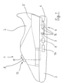
- a shoe 1 in the form of a sports shoe can be seen, which has a shoe upper 2 and a sole 3.
- the shoe 1 is laced by means of a twist lock 4 (ie a central lock), whereby by turning a tensioning roller 6 at least one tensioning element 5 is wound onto the tensioning roller 6 and thus the shoe upper 2 is tensioned or laced on the foot of the wearer of the shoe 1.
- the tensioning element 5 and its course are shown in Fig. 1 only very schematically indicated.
- the twist lock 4 is arranged in the sole 3 of the shoe 1.
- a switching element 8 for operating the twist lock 4 is arranged remotely from the twist lock 4 on the instep 13 of the shoe 1. This provides convenient access to the switching element 8 for operating the twist lock 4.
- the electric motor 7 required for operating the rotary closure 4 is indicated; it drives the tension roller 6 via a gear 16.
- the operation of the electric motor 7 for opening and closing the rotary closure 4 is initiated by a control 9 which is connected to the switching element 8.
- a battery 14 is provided to supply energy to the motor 7 and the control 9.
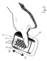
- the switching element 8 has, as it Figure 2 As can be seen, the shoe has a surface 11 which is provided with a number of touch-sensitive sensors 10. Specifically, five touch-sensitive sensors 10 are arranged linearly next to one another. The individual touch-sensitive sensors 10 are designed as capacitive sensors, which are known as such in the prior art. They react to contact with the finger 15 of the user of the shoe 1.
- the user moves his finger 15 over the touch-sensitive sensors 10 in a first direction R1. If the control detects said contact between the sensors 10, it initiates the start of a first lacing force level, i.e. the electric motor 7 is operated with a first, predetermined maximum value for the motor current, for example 1.5 A.
- Light elements 12 in the form of LEDs are arranged on the switching element 8. By activating one or more of the light elements 12, the lacing force level reached can be displayed to the user.
- a second, higher lacing force level can be reached; a second, predetermined maximum value for the motor current can now be 2.5 A, for example.
- a third, predetermined maximum value for the motor current can now be 3.5 A, for example.
- the light elements 12 can in turn be used to display the current lacing force level.
- the user moves his finger 15 over the surface 11, i.e. the touch-sensitive sensors 10, in a second direction R2, which is opposite to the first direction R1.
- the control 9 then causes the shoe to open completely.
- the electric motor 7 then moves into the completely relaxed state, which can be determined by a corresponding angle of rotation sensor on the tension roller 6.
- the user therefore does not have to operate a closing or opening switch for a longer period of time - as in the prior art; it is sufficient to swipe over the touch-sensitive sensors 10 in the manner described.
Landscapes
- Engineering & Computer Science (AREA)
- Microelectronics & Electronic Packaging (AREA)
- Footwear And Its Accessory, Manufacturing Method And Apparatuses (AREA)
- Health & Medical Sciences (AREA)
- General Health & Medical Sciences (AREA)
- Physical Education & Sports Medicine (AREA)
Description
- Die Erfindung betrifft ein Verfahren zum Schnüren eines Schuhs, insbesondere eines Sportschuhs, wobei der Schuh aufweist:
- ein Schuhoberteil und eine mit dem Schuhoberteil verbundene Sohle,
- einen Drehverschluss zum Schnüren des Schuhs am Fuß des Trägers mittels mindestens eines Spannelements, wobei der Drehverschluss eine drehbar angeordnete Spannrolle zum Aufwickeln des Spannelements aufweist, wobei die Spannrolle mittels eines Elektromotors angetrieben wird,
- ein Schaltelement, das mit einer Steuerung in Verbindung steht, wobei über das Schaltelement und die Steuerung der Elektromotor betätigt werden kann,
- Des weiteren betrifft die Erfindung einen Schuh, insbesondere einen Sportschuh.
- Ein Schuh mit einem elektromotorisch betriebenen Drehverschlusses ist aus der
DE 298 17 003 U1 bekannt. Hier wird eine Spannrolle zum Aufwickeln eines Spannelements elektromotorisch angetrieben, so dass der Schuh automatisch geschnürt und entschnürt werden kann. - Die
WO 2014/036374 A1 offenbart einen motorisch betriebenen Drehverschluss in einem Schuh, der mit einem Mobiltelefon in Verbindung steht und über dieses gesteuert werden kann. Ein motorisch betätigtes Schließsystem in einem Schuh offenbart auch dieUS 2013/0104429 A1 , wobei zur Betätigung des Drehverschlusses am Schuh verschiedene Tasten angeordnet sind, die für entsprechende Funktionen gedrückt werden. - Zum Schnüren des Schuhs wird vom Benutzer ein elektrischer Schalter betätigt und der Elektromotor des Drehverschlusses solange aktiviert, wie der Schalter gedrückt wird. Entsprechend steigt die Schnürkraft allmählich an. Ist ein gewünschtes Schnürkraftniveau erreicht, lässt der Benutzer den Schalter wieder los. Zum Entschnüren des Schuhs kann entsprechend ein anderer Schalter betätigt werden.
- Demgemäß benötigt das Schnüren des Schuhs eine entsprechende Zeit, während der der Benutzer den Schalter drücken muss. Außerdem muss das jeweils gewünschte Schnürkraftniveau bei jeder Schnürung vom Benutzer eingestellt werden.
- Der Erfindung liegt die Aufgabe zugrunde, ein Verfahren der eingangs genannten Art so weiterzubilden, dass das Schnüren des Schuhs komfortabler und in vereinfachter Weise bewerkstelligt werden kann. Dabei soll es insbesondere möglich sein, bedienerfreundlich die Schnürung des Schuhs an individuelle Wünsche anpassen zu können. Damit soll ohne großen Bedienaufwand der Schuh gemäß den Wünschen des Benutzers mit einem definierten Schnürkraftniveau anlegbar sein. Weiterhin soll ein entsprechender Schuh zur Verfügung gestellt werden.
- Die Lös u n g dieser Aufgabe durch die Erfindung ist dadurch gekennzeichnet, dass das Schaltelement auf dem Rist des Schuhs angeordnet ist, wobei das Schaltelement eine Anzahl nebeneinander angeordneter berührungssensitiver Sensoren aufweist, die eine für den Benutzer des Schuhs (insbesondere für einen Finger des Benutzers) zugängliche Oberfläche bilden, wobei ein erstes Spannelement angeordnet ist, das auf der lateralen Seite des Schuhoberteils verläuft, wobei ein zweites Spannelement angeordnet ist, das auf der medialen Seite des Schuhoberteils verläuft, wobei beide Spannelemente mit ihren beiden Enden an der Spannrolle befestigt sind und jeweils einen geschlossenen Kurvenzug auf der lateralen Seite und auf der medialen Seite des Schuhoberteils bilden, wobei das Verfahren die Schritte umfasst:
- Überstreichen der Oberfläche der berührungssensitiven Sensoren durch den Benutzer, vorzugsweise mit dem Finger, in eine erste Richtung,
- Detektieren des Signals der berührungssensitiven Sensoren von der Steuerung und Veranlassung des Schnürens des Schuhs am Fuß des Trägers mit einem ersten Schnürkraftniveau durch die Steuerung und den Elektromotor.
- Das Verfahren kann weiterhin die Schritte umfassen:
- Nochmaliges Überstreichen der Oberfläche der berührungssensitiven Sensoren durch den Benutzer, vorzugsweise mit dem Finger, in die erste Richtung,
- Detektieren des Signals der berührungssensitiven Sensoren von der Steuerung und Veranlassung des Schnürens des Schuhs am Fuß des Trägers durch die Steuerung und den Elektromotor mit einem zweiten Schnürkraftniveau, das höher ist als das erste Schnürkraftniveau.
- Somit kann ein zweites, höheres Schnürkraftniveau in einfacher Weise angefahren werden. Dieses Prinzip lässt sich auch fortsetzen: Das Verfahren kann weiterhin die Schritte umfassen:
- Nochmaliges Überstreichen der Oberfläche der berührungssensitiven Sensoren durch den Benutzer, vorzugsweise mit dem Finger, in die erste Richtung,
- Detektieren des Signals der berührungssensitiven Sensoren von der Steuerung und Veranlassung des Schnürens des Schuhs am Fuß des Trägers durch die Steuerung und den Elektromotor mit einem dritten Schnürkraftniveau, das höher ist als das zweite Schnürkraftniveau.
- Es können dabei auch weitere Überstreichungen der berührungssensitiven Sensoren zur weiteren schrittweisen Steigerung des Schnürkraftniveaus erfolgen. Ein Schnürkraftniveau wird dabei bevorzugt durch Vorgabe des Stroms definiert, mit dem der Elektromotor betrieben wird (siehe unten).
- Das Öffnen des Schuhs oder die Reduzierung des Schnürkraftniveaus erfolgt bevorzugt, in dem folgende Schritte ausgeführt werden:
- Überstreichen der Oberfläche der berührungssensitiven Sensoren durch den Benutzer, vorzugsweise mit dem Finger, in eine zweite Richtung, die der ersten Richtung entgegengesetzt ist,
- Detektieren des Signals der berührungssensitiven Sensoren von der Steuerung und Veranlassung des Öffnens des Schuhs oder der Reduzierung des Schnürkraftniveaus durch die Steuerung und den Elektromotor.
- Für die vollständig entschnürte Endposition kann die Spannrolle mit einem Drehwinkelsensor versehen sein, der in der Lage ist, die Null-Position der Spannrolle zu erkennen.
- Das oben genannte Überstreichen der Oberfläche der berührungssensitiven Sensoren erfolgt nach einer bevorzugten Vorgehensweise dergestalt, dass der Benutzer (bevorzugt mittels eines Fingers) die Sensoren komplett überstreicht, d. h. über die gesamte Erstreckung der Oberfläche der Sensoren. Auf diese Art und Weise kann - wie beschrieben - das Schnürkraftniveau schrittweise bzw. in Stufen erhöht werden; gleichermaßen kann damit (wenn die Oberfläche in die Gegenrichtung überstrichen wird) das Schnürkraftniveau reduziert werden bzw. der Schuh komplett geöffnet werden.
- Allerdings ist es genauso auch möglich, die Oberfläche der berührungssensitiven Sensoren nicht vollständig, sondern nur über einen Teil ihrer Erstreckung (mit dem Finger) zu überstreichen. Die Steuerung kann dann in Abhängigkeit der Länge, über die der Benutzer die Oberfläche überstrichen hat, ein (bevorzugt proportionales) Signal an den Elektromotor geben, so dass die Spannung der Schnürung im entsprechenden Maße erhöht oder (bei Überstreichen in der Gegenrichtung) reduziert wird.
- Somit erlaubt das vorgeschlagene Verfahren ein stufenweises Schließen (Schnüren) und Öffnen (Entspannen) des Schuhs, wozu die Oberfläche der berührungssensitiven Sensoren komplett oder auch nur zu einem Teil überstrichen wird, um besagtes Schnüren bzw. Öffnen fein einstellen zu können.
- Somit besteht die Möglichkeit, durch einfaches Überstreichen der Anzahl berührungssensitiver Sensoren (in die erste Richtung) gezielt definierte Schnürkraftniveaus des Schuhs anzufahren und auch das Öffnen des Schuhs, d.h. die Entspannung des Spannelements, durch einmaliges Überstreichen der Sensoren (in die zweite Richtung) vorzunehmen.
- Damit werden das Schnüren und das Lösen der Schnürung in sehr einfacher und komfortabler Weise möglich.
- Am oder auf dem Schaltelement kann eine Anzahl an Leuchtelementen, insbesondere in Form von Light-Emitting Diodes (LED), angeordnet sein, wobei das aktuelle Schnürkraftniveau durch die Anzahl der aktivierten Leuchtelemente angezeigt wird. Somit kann in einfacher Weise dem Benutzer des Schuhs angezeigt werden, wie stark der Schuh gegenwärtig am Fuß geschnürt ist. Je mehr LEDs aufleuchten, desto stärker ist der Schuh gespannt. Auch der geöffnete Zustand des Schuhs kann über die LEDs angezeigt werden.
- Der vorgeschlagene Schuh mit Drehverschluss und Schaltelement zeichnet sich erfindungsgemäß dadurch aus, dass das Schaltelement auf dem Rist des Schuhs angeordnet ist, wobei ein erstes Spannelement angeordnet ist, das auf der lateralen Seite des Schuhoberteils verläuft, wobei ein zweites Spannelement angeordnet ist, das auf der medialen Seite des Schuhoberteils verläuft, wobei beide Spannelemente mit ihren beiden Enden an der Spannrolle befestigt sind und jeweils einen geschlossenen Kurvenzug auf der lateralen Seite und auf der medialen Seite des Schuhoberteils bilden, wobei das Schaltelement durch eine Anzahl nebeneinander angeordneter berührungssensitiver Sensoren gebildet wird, die eine für den Benutzer des Schuhs (insbesondere für einen Finger des Benutzers) zugängliche Oberfläche bilden. Die gemeinsame Oberfläche der Sensoren ist dabei möglichst glatt und eben ausgeführt.
- Dies ist so zu verstehen, dass durch Überstreichen der Oberfläche die einzelnen berührungssensitiven Sensoren aktiviert werden können, um die oben genannte Funktionalität zu erzeugen.
- Die einzelnen berührungssensitiven Sensoren sind dabei bevorzugt als kapazitive Sensoren ausgebildet.
- Die einzelnen berührungssensitiven Sensoren sind bevorzugt nebeneinander in einer linearen Anordnung positioniert, wobei vorzugsweise zwischen drei und sieben berührungssensitive Sensoren nebeneinander angeordnet sind. Am oder auf dem Schaltelement ist bevorzugt eine Anzahl Leuchtelemente, insbesondere LEDs, angeordnet.
- Gemäß einer bevorzugten Ausführungsform sind das Schaltelement und der Drehverschluss an unterschiedlichen Stellen des Schuhs angeordnet. Das Schaltelement ist erfindungsgemäß auf dem Rist des Schuhs angeordnet; der Drehverschluss ist bevorzugt in der Sohle des Schuhs angeordnet.
- Allerdings sind natürlich auch andere Positionen für das Schaltelement und den Drehverschluss möglich. Beide Elemente können als Einheit auf dem Rist angeordnet sein. Möglich ist auch die Anordnung des Schaltelements im Seitenbereich des Schuhs bzw. des Schuhoberteils oder im Fersenbereich.
- Auch hier ist wieder eine Kombination mit dem Drehverschluss zu einer Einheit (bestehend aus Drehverschluss und Schaltelement) möglich.
- Wie oben erläutert, wird das Überstreichen der Oberfläche der berührungssensitiven Sensoren durch den Benutzer in der Regel mit dem Finger erfolgen. Allerdings ist dies nicht zwingend; es kann diesbezüglich auch vorgesehen werden, dass zum Überstreichen ein Hilfsmittel (z. B. ein Stift) eingesetzt wird.
- Im Schuhoberteil können Federmittel angeordnet sein, die das Schuhoberteil entgegen der Wirkung des Spannelements in eine Geöffnet-Position vorspannen. Damit wird erreicht, dass nach Öffnen des Drehverschlusses das Schuhoberteil in eine geöffnete Stellung "aufklappt" und so ein leichteres An- und Ausziehen des Schuhs ermöglicht.
- Zur Energieversorgung ist bevorzugt eine wiederaufladbare Batterie im Schuh angeordnet, die induktiv bzw. kontaktfrei aufladbar ist. Die Batterie, die für den Betrieb des Motors benötigt wird, ist also in diesem Falle als wiederaufladbare Batterie ausgebildet und wird über eine Induktionsspule mit einem Ladestrom versorgt. Die Batterie kann in einer (Zwischen)Sohle des Schuhs angeordnet sein. Die für das Aufladen benötigte Elektronik kann direkt an der Batterie platziert sein. Durch das Vorsehen einer Induktionsspule kann die Batterie des Schuhs kontaktlos aufgeladen werden. Hierzu kann der Schuh auf einer entsprechenden Ladeplatte platziert und so die Batterie aufgeladen werden. Die oben erwähnten LEDs können auch zum Anzeigen des Ladens bzw. des Ladezustands genutzt werden. Beispielsweise können während des Aufladens die LEDs blinken, wobei immer mehr LEDs blinken, je stärker die Batterie aufgeladen ist.
- Vorgesehen kann auch werden, dass der Ladezustand der Batterie während der Benutzung des Schuhs durch die LEDs angezeigt wird. So ist es beispielsweise möglich, dass ab einem gewissen Ladezustand (z. B. wenn die Batterie weniger als 50 % des maximalen Ladezustands aufweist) die LEDs zu blinken anfangen.
- Die hier angesprochenen berührungssensitiven Sensoren sind als solche handelsüblich und werden auch als "swipe sensor" oder "touch panel" bezeichnet. Es handelt sich generell um eine Anzahl (meist zwischen drei und sieben) nebeneinander angeordneter Sensoren, die jeweils berührungsempfindlich sind, wodurch es der Steuerung möglich wird, durch die Abfolge der gemessenen Impulse der einzelnen Sensoren beim Überstreichen in die erste oder zweite Richtung zu erkennen, welche Maßnahme (Schließen oder Öffnen) durchgeführt werden soll.
- Das erste Schnürkraftniveau wird dabei vorzugsweise durch einen ersten vorgegebenen maximalen Strom definiert, den die Steuerung dem Elektromotor beim Schnürvorgang vorgibt; besagter Strom beträgt dabei bevorzugt zwischen 1,1 A und 1,9 A. Das zweite Schnürkraftniveau wird analog bevorzugt durch einen zweiten vorgegebenen maximalen Strom definiert, den die Steuerung dem Elektromotor beim Schnürvorgang vorgibt, wobei der zweite maximale Strom höher ist als der erste maximale Strom; besagter Strom liegt bevorzugt zwischen 2,1 A und 2,9 A. Das dritte Schnürkraftniveau wird entsprechend bevorzugt durch einen dritten vorgegebenen maximalen Strom definiert, den die Steuerung dem Elektromotor beim Schnürvorgang vorgibt, wobei der dritte maximale Strom höher ist als der zweite maximale Strom; der Strom liegt bevorzugt zwischen 3,1 A und 3,9 A.
- Besagte Schnürkraftniveaus sind dabei also durch Vorgabe eines entsprechenden Motorstroms definiert (z. B. erstes Niveau: 1,5 A - zweites Niveau: 2,5 A - drittes Niveau: 3,5 A), so dass der Motor mit korrespondierenden maximalen Drehmomenten betrieben wird, was wiederum über das bevorzugt zum Einsatz kommende Getriebe zwischen Motor und Spannrolle zu einer korrespondierenden zunehmenden Zugkraft im Spannelement führt.
- Erfindungsgemäß ist ein erstes Spannelement angeordnet, das auf der lateralen Seite des Schuhoberteils verläuft, wobei ein zweites Spannelement angeordnet ist, das auf der medialen Seite des Schuhoberteils verläuft; beide Spannelemente sind dabei mit ihren beiden Enden an der Spannrolle befestigt und bilden jeweils einen geschlossenen Kurvenzug auf der lateralen Seite bzw. auf der medialen Seite des Schuhoberteils.
- Die beiden Kurvenzüge der beiden Spannelemente auf der lateralen Seite und auf der medialen Seite des Schuhoberteils sind vorzugsweise im wesentlichen symmetrisch zu einer Mittenebene des Schuhs ausgebildet, wobei die Mittenebene vertikal und in Längsrichtung des Schuhs verläuft.
- Besonders bevorzugt ist eine spezielle Führung der beiden Spannelemente auf den beiden Seiten des Schuhoberteils vorgesehen, um eine optimale Verteilung des Schnürzugs und so eine optimale Anlage des Schuhs am Fuß des Trägers zu erreichen.
- Hiernach kann jedes Spannelement von der Spannrolle zu einem ersten Umlenkelement verlaufen, das das Spannelement im unteren Bereich des Schuhoberteils sowie an einer Stelle umlenkt, die im Bereich zwischen 30 % und 42 % der Schuhlängserstreckung, gerechnet von der Schuhspitze, liegt.
- Weiterhin kann vorgesehen sein, dass jedes Spannelement vom ersten Umlenkelement zu einem zweiten Umlenkelement verläuft, das das Spannelement im unteren Bereich des Schuhoberteils sowie an einer Stelle umlenkt, die im Bereich zwischen 50 % und 60 % der Schuhlängserstreckung, gerechnet von der Schuhspitze, liegt.
- Weiterhin kann jedes Spannelement vom zweiten Umlenkelement zu einem dritten Umlenkelement verlaufen, wobei das Spannelement im oberen Bereich des Schuhoberteils benachbart zum Drehverschluss liegt.
- Jedes Spannelement kann ferner vom dritten Umlenkelement zu einem vierten Umlenkelement verlaufen, das das Spannelement im unteren Bereich des Schuhoberteils sowie an einer Stelle umlenkt, die im Bereich zwischen 55 % und 70 % der Schuhlängserstreckung, gerechnet von der Schuhspitze, liegt.
- Schließlich kann vorgesehen sein, dass jedes Spannelement vom vierten Umlenkelement zu einem fünften Umlenkelement verläuft, das das Spannelement im Bereich zwischen 33 % und 66 % der Gesamthöhe des Schuhs sowie an einer Stelle umlenkt, die im Bereich zwischen 75 % und 90 % der Schuhlängserstreckung, gerechnet von der Schuhspitze, liegt, wobei das Spannelement vom fünften Umlenkelement zur Spannrolle verläuft.
- Die genannte Anordnung der Umlenkelemente im unteren Bereich des Schuhoberteils ist dabei so zu verstehen, dass die Umlenkelemente an der Sohle des Schuhs bzw. etwas oberhalb der Sohle am Schuhoberteil fixiert sind und somit die Umlenkstelle des Spannelements in einem Höhenbereich liegt, der unterhalb einer Marke von 20 % der vertikalen Erstreckung (wenn der Schuh auf dem Boden steht) des Schuhoberteils 2 liegt.
- Mindestens eines der Umlenkelemente kann dabei als Schlaufe ausgebildet sein, die am Schuhoberteil und/oder an der Sohle des Schuhs befestigt, insbesondere angenäht, ist.
- Die Schlaufen können dabei aus einem Band bestehen, das am Schuhoberteil und/oder an der Sohle des Schuhs angenäht ist.
- Das genannte fünfte Umlenkelement umgreift bevorzugt den Fersenbereich des Schuhs. Dabei ist bevorzugt vorgesehen, dass das fünfte Umlenkelement in der Seitenansicht des Schuhs eine V-förmige Ausgestaltung aufweist, wobei in der Seitenansicht des Schuhs der eine Schenkel der V-förmigen Struktur im oberen Fersenbereich und der andere Schenkel der V-förmigen Struktur im unteren Fersenbereich endet.
- Die Spannelemente sind bevorzugt Spanndrähte. Sie können Polyamid aufweisen oder aus diesem Material bestehen.
- In vorteilhafter Weise kann so der Bedienungskomfort bei der Benutzung eines Schuhs mit elektromotorischem Schnürsystem per Drehverschluss verbessert werden.
- Das vorgeschlagene Verfahren kann auch dahingehend weiterentwickelt werden, dass am oder im Schuh ein Drucksensor angeordnet ist, der den Grad der Schnürspannung des Schuhs am Fuß des Trägers erfasst. Dieser Druck kann mit einem Wert verglichen werden, der in der Steuerung gespeichert ist. Wird während des Tragens des Schuhs ein zu hoher Druck festgestellt, kann vorgesehen werden, dass die Steuerung autark eine Verminderung der Schnürspannung veranlasst. Umgekehrt kann bei einem zu geringen Druck auch ein Nachschnüren des Schuhs veranlasst werden, was die Steuerung autark vornimmt.
- In der Zeichnung ist ein Ausführungsbeispiel der Erfindung dargestellt. Es zeigen:
- Fig. 1
- schematisch in der Seitenansicht einen teils geschnitten dargestellten Sportschuh, der mit einem Drehverschluss geschnürt werden kann, und
- Fig. 2
- in perspektivischer Darstellung ein Schaltelement zur Betätigung des Drehverschlusses durch den Finger der den Sportschuh benutzenden Person.
- In
Figur 1 ist ein Schuh 1 in Form eines Sportschuhs zu sehen, der ein Schuhoberteil 2 und eine Sohle 3 aufweist. Die Schnürung des Schuhs 1 erfolgt mittels eines Drehverschlusses 4 (d. h. eines Zentralverschlusses), wobei durch Drehen einer Spannrolle 6 mindestens ein Spannelement 5 auf der Spannrolle 6 aufgewickelt wird und so das Schuhoberteil 2 am Fuß des Trägers des Schuhs 1 gespannt bzw. geschnürt wird. Das Spannelement 5 und sein Verlauf sind inFig. 1 nur sehr schematisch angedeutet. - Der Drehverschluss 4 ist in der Sohle 3 des Schuhs 1 angeordnet. Ein Schaltelement 8 zur Betätigung des Drehverschlusses 4 ist indes entfernt vom Drehverschluss 4 auf dem Rist 13 des Schuhs 1 angeordnet. Somit ist eine bequeme Zugänglichkeit zum Schaltelement 8 für die Betätigung des Drehverschlusses 4 gegeben.
- Der für die Betätigung des Drehverschlusses 4 benötigte Elektromotor 7 ist angedeutet; er treibt über ein Getriebe 16 die Spannrolle 6 an. Die Betätigung des Elektromotors 7 zum Öffnen und Schließen des Drehverschlusses 4 wird von einer Steuerung 9 veranlasst, die mit dem Schaltelement 8 verbunden ist. Zur Energieversorgung des Motors 7 und der Steuerung 9 ist eine Batterie 14 vorgesehen.
- Zum Schließen und Öffnen des Schuhs 1 geht der Benutzer wie folgt vor:
Das Schaltelement 8 weist, wie es ausFigur 2 ersichtlich ist, eine Oberfläche 11 auf, die mit einer Anzahl berührungssensitiver Sensoren 10 versehen ist. Konkret sind vorliegend fünf berührungssensitive Sensoren 10 linear nebeneinander angeordnet. Die einzelnen berührungssensitiven Sensoren 10 sind als kapazitive Sensoren ausgebildet, die als solche im Stand der Technik bekannt sind. Sie reagieren auf die Kontaktnahme mit dem Finger 15 des Benutzers des Schuhs 1. - Zum Schließen des Schuhs überstreicht der Benutzer mit seinem Finger 15 die berührungssensitiven Sensoren 10 in eine erste Richtung R1. Detektiert die Steuerung besagte Kontaktierung der Sensoren 10, veranlasst sie das Anfahren eines ersten Schnürkraftniveaus, d. h. der Elektromotor 7 wird mit einem ersten, vorgegebenen Maximalwert für den Motorstrom betrieben, beispielsweise 1,5 A.
- Am Schaltelement 8 sind Leuchtelemente 12 in Form von LEDs angeordnet. Durch Aktivierung eines oder mehrerer der Leuchtelemente 12 kann das angefahrene Schnürkraftniveau dem Benutzer angezeigt werden.
- Wird das Überstreichen der Sensoren 10 mit dem Finger 15 in die erste Richtung R1 wiederholt, kann ein zweites, höheres Schnürkraftniveau angefahren werden; dabei kann ein zweiter, vorgegebener Maximalwert für den Motorstrom jetzt beispielsweise bei 2,5 A liegen.
- Bei nochmaligem Überstreichen der Sensoren 10 kann das Schnürkraftniveau weiter gesteigert werden; ein dritter, vorgegebener Maximalwert für den Motorstrom kann jetzt beispielsweise bei 3,5 A liegen.
- Die Leuchtelemente 12 können wiederum genutzt werden, um das jeweils aktuelle Schnürkraftniveau anzuzeigen.
- Zum Öffnen des Schuhs 1 überstreicht der Benutzer mit seinem Finger 15 die Oberfläche 11, d. h. die berührungssensitiven Sensoren 10, in eine zweite Richtung R2, die zur ersten Richtung R1 entgegengesetzt ist. Die Steuerung 9 veranlasst dann das vollständige Öffnen des Schuhs. Der Elektromotor 7 fährt dann in den vollständig entspannten Zustand, der durch einen entsprechenden Drehwinkelsensor an der Spannrolle 6 ermittelt werden kann.
- Der Benutzer muss also nicht - wie im Stand der Technik - längere Zeit einen Schließ- oder Öffnungs-Schalter betätigen; es reicht das Überstreichen der berührungssensitiven Sensoren 10 in der beschriebenen Weise.
- Vorteilhaft kann der Benutzer hierdurch ein für seine Wünsche passendes Schnürkraftniveau gezielt anfahren, ohne dass er dies durch entsprechend langes Drücken des Schließ-Schalters einstellen muss.
-
- 1
- Schuh
- 2
- Schuhoberteil
- 3
- Sohle
- 4
- Drehverschluss
- 5
- Spannelement
- 6
- Spannrolle
- 7
- Elektromotor
- 8
- Schaltelement
- 9
- Steuerung
- 10
- berührungssensitiver Sensor
- 11
- Oberfläche
- 12
- Leuchtelement (LED)
- 13
- Rist
- 14
- Batterie
- 15
- Finger
- 16
- Getriebe
- R1
- erste Richtung
- R2
- zweite Richtung
Claims (13)
- Verfahren zum Schnüren eines Schuhs (1), insbesondere eines Sportschuhs, wobei der Schuh (1) aufweist:- ein Schuhoberteil (2) und eine mit dem Schuhoberteil (2) verbundene Sohle (3),- einen Drehverschluss (4) zum Schnüren des Schuhs (1) am Fuß des Trägers mittels mindestens eines Spannelements (5), wobei der Drehverschluss (4) eine drehbar angeordnete Spannrolle (6) zum Aufwickeln des Spannelements (5) aufweist, wobei die Spannrolle (6) mittels eines Elektromotors (7) angetrieben wird,- ein Schaltelement (8), das mit einer Steuerung (9) in Verbindung steht, wobei über das Schaltelement (8) und die Steuerung (9) der Elektromotor (7) betätigt werden kann,wobei das Schnüren des Schuhs (1) erfolgt, indem der Benutzer des Schuhs (1) das Schaltelement (8), vorzugsweise mit einem Finger (15), betätigt,dadurch gekennzeichnet,dass das Schaltelement (8) auf dem Rist des Schuhs (1) angeordnet ist,wobei das Schaltelement (8) eine Anzahl nebeneinander angeordneter berührungssensitiver Sensoren (10) aufweist, die eine für den Benutzer zugängliche Oberfläche (11) bilden,wobei ein erstes Spannelement (5) angeordnet ist, das auf der lateralen Seite des Schuhoberteils (2) verläuft, wobei ein zweites Spannelement (5) angeordnet ist, das auf der medialen Seite des Schuhoberteils (2) verläuft, wobei beide Spannelemente (5) mit ihren beiden Enden an der Spannrolle (6) befestigt sind und jeweils einen geschlossenen Kurvenzug auf der lateralen Seite und auf der medialen Seite des Schuhoberteils (2) bilden,wobei das Verfahren die Schritte umfasst:- Überstreichen der Oberfläche (11) der berührungssensitiven Sensoren (10) durch den Benutzer, vorzugsweise mit dem Finger (15), in eine erste Richtung (R1),- Detektieren des Signals der berührungssensitiven Sensoren (10) von der Steuerung (9) und Veranlassung des Schnürens des Schuhs am Fuß des Trägers mit einem ersten Schnürkraftniveau durch die Steuerung (9) und den Elektromotor (7).
- Verfahren nach Anspruch 1, dadurch gekennzeichnet, dass das Verfahren weiterhin die Schritte umfasst:- Nochmaliges Überstreichen der Oberfläche (11) der berührungssensitiven Sensoren (10) durch den Benutzer, vorzugsweise mit dem Finger (15), in die erste Richtung (R1),- Detektieren des Signals der berührungssensitiven Sensoren (10) von der Steuerung (9) und Veranlassung des Schnürens des Schuhs am Fuß des Trägers durch die Steuerung (9) und den Elektromotor (7) mit einem zweiten Schnürkraftniveau, das höher ist als das erste Schnürkraftniveau.
- Verfahren nach Anspruch 2, dadurch gekennzeichnet, dass das Verfahren weiterhin die Schritte umfasst:- Nochmaliges Überstreichen der Oberfläche (11) der berührungssensitiven Sensoren (10) durch den Benutzer, vorzugsweise mit dem Finger (15), in die erste Richtung (R1),- Detektieren des Signals der berührungssensitiven Sensoren (10) von der Steuerung (9) und Veranlassung des Schnürens des Schuhs am Fuß des Trägers durch die Steuerung (9) und den Elektromotor (7) mit einem dritten Schnürkraftniveau, das höher ist als das zweite Schnürkraftniveau.
- Verfahren nach einem der Ansprüche 1 bis 3, dadurch gekennzeichnet, dass das Verfahren weiterhin die Schritte umfasst:- Überstreichen der Oberfläche (11) der berührungssensitiven Sensoren (10) durch den Benutzer, vorzugsweise mit dem Finger (15), in eine zweite Richtung (R2), die der ersten Richtung (R1) entgegengesetzt ist,- Detektieren des Signals der berührungssensitiven Sensoren (10) von der Steuerung (9) und Veranlassung des Öffnens des Schuhs oder der Reduzierung des Schnürkraftniveaus durch die Steuerung (9) und den Elektromotor (7).
- Verfahren nach einem der Ansprüche 1 bis 4, dadurch gekennzeichnet, dass am oder auf dem Schaltelement (8) eine Anzahl an Leuchtelementen (12), insbesondere an LEDs, angeordnet ist, wobei das aktuelle Schnürkraftniveau durch die Anzahl der aktivierten Leuchtelemente angezeigt wird.
- Schuh (1), insbesondere Sportschuh, der aufweist:- ein Schuhoberteil (2) und eine mit dem Schuhoberteil (2) verbundene Sohle (3),- einen Drehverschluss (4) zum Schnüren des Schuhs (1) am Fuß des Trägers mittels mindestens eines Spannelements (5), wobei der Drehverschluss (4) eine drehbar angeordnete Spannrolle (6) zum Aufwickeln des Spannelements (5) aufweist, wobei die Spannrolle (6) mittels eines Elektromotors (7) angetrieben wird,- ein Schaltelement (8), das mit einer Steuerung (9) in Verbindung steht, wobei über das Schaltelement (8) und die Steuerung (9) der Elektromotor (7) betätigt werden kann,dadurch gekennzeichnet,dass das Schaltelement (8) auf dem Rist des Schuhs (1) angeordnet ist,wobei ein erstes Spannelement (5) angeordnet ist, das auf der lateralen Seite des Schuhoberteils (2) verläuft, wobei ein zweites Spannelement (5) angeordnet ist, das auf der medialen Seite des Schuhoberteils (2) verläuft, wobei beide Spannelemente (5) mit ihren beiden Enden an der Spannrolle (6) befestigt sind und jeweils einen geschlossenen Kurvenzug auf der lateralen Seite und auf der medialen Seite des Schuhoberteils (2) bilden,wobei das Schaltelement (8) durch eine Anzahl nebeneinander angeordneter berührungssensitiver Sensoren (10) gebildet wird, die eine für den Benutzer zugängliche Oberfläche (11) bilden.
- Schuh nach Anspruch 6, dadurch gekennzeichnet, dass die einzelnen berührungssensitiven Sensoren (10) als kapazitive Sensoren ausgebildet sind.
- Schuh nach Anspruch 6 oder 7, dadurch gekennzeichnet, dass die einzelnen berührungssensitiven Sensoren (10) nebeneinander in einer linearen Anordnung positioniert sind, wobei vorzugsweise zwischen drei und sieben berührungssensitive Sensoren (10) nebeneinander angeordnet sind.
- Schuh nach einem der Ansprüche 6 bis 8, dadurch gekennzeichnet, dass am oder auf dem Schaltelement (8) eine Anzahl Leuchtelemente (12), insbesondere LEDs, angeordnet ist.
- Schuh nach einem der Ansprüche 6 bis 9, dadurch gekennzeichnet, dass das Schaltelement (8) und der Drehverschluss (4) an unterschiedlichen Stellen des Schuhs (1) angeordnet sind.
- Schuh nach Anspruch 10, dadurch gekennzeichnet, dass der Drehverschluss (4) in der Sohle (3) des Schuhs (1) angeordnet ist.
- Schuh nach einem der Ansprüche 6 bis 11, dadurch gekennzeichnet, dass im Schuhoberteil (2) Federmittel angeordnet sind, die das Schuhoberteil (2) entgegen der Wirkung des Spannelements (5) in eine Geöffnet-Position vorspannen.
- Schuh nach einem der Ansprüche 6 bis 12, dadurch gekennzeichnet, dass zur Energieversorgung eine wiederaufladbare Batterie (14) im Schuh (1) angeordnet ist, die induktiv und/oder kontaktfrei aufladbar ist.
Applications Claiming Priority (1)
| Application Number | Priority Date | Filing Date | Title |
|---|---|---|---|
| PCT/EP2016/001968 WO2018095501A1 (de) | 2016-11-22 | 2016-11-22 | Verfahren zum schnüren eines schuhs, insbesondere eines sportschuhs, und schuh, insbesondere sportschuh |
Publications (3)
| Publication Number | Publication Date |
|---|---|
| EP3544460A1 EP3544460A1 (de) | 2019-10-02 |
| EP3544460C0 EP3544460C0 (de) | 2025-01-08 |
| EP3544460B1 true EP3544460B1 (de) | 2025-01-08 |
Family
ID=57394520
Family Applications (1)
| Application Number | Title | Priority Date | Filing Date |
|---|---|---|---|
| EP16801134.4A Active EP3544460B1 (de) | 2016-11-22 | 2016-11-22 | Verfahren zum schnüren eines schuhs, insbesondere eines sportschuhs, und schuh, insbesondere sportschuh |
Country Status (12)
| Country | Link |
|---|---|
| US (2) | US11805854B2 (de) |
| EP (1) | EP3544460B1 (de) |
| JP (1) | JP6882472B2 (de) |
| KR (1) | KR102519623B1 (de) |
| CN (1) | CN110049693A (de) |
| AU (1) | AU2016430821A1 (de) |
| BR (1) | BR112019010424B1 (de) |
| CA (1) | CA3042721C (de) |
| ES (1) | ES3018259T3 (de) |
| MX (1) | MX2019005959A (de) |
| RU (1) | RU2728126C1 (de) |
| WO (1) | WO2018095501A1 (de) |
Families Citing this family (24)
| Publication number | Priority date | Publication date | Assignee | Title |
|---|---|---|---|---|
| US11103030B2 (en) | 2015-10-07 | 2021-08-31 | Puma SE | Article of footwear having an automatic lacing system |
| US11185130B2 (en) | 2015-10-07 | 2021-11-30 | Puma SE | Article of footwear having an automatic lacing system |
| US11033079B2 (en) | 2015-10-07 | 2021-06-15 | Puma SE | Article of footwear having an automatic lacing system |
| EP3383211B1 (de) | 2015-12-02 | 2019-09-25 | Puma Se | Verfahren zum schnüren eines schuhs, insbesondere eines sportschuhs |
| US11357290B2 (en) | 2016-03-15 | 2022-06-14 | Nike, Inc. | Active footwear sensor calibration |
| EP4631384A3 (de) | 2016-03-15 | 2025-10-22 | Nike Innovate C.V. | Kapazitive fusspräsenzerfassung für schuhwerk |
| US11064768B2 (en) | 2016-03-15 | 2021-07-20 | Nike, Inc. | Foot presence signal processing using velocity |
| JP7295017B2 (ja) | 2016-11-22 | 2023-06-20 | プーマ エス イー | 着用者に対して衣類を装着するもしくは取り去る、または人が持ち運ぶ荷物を閉じる、装着する、開放する、もしくは取り去るための方法 |
| EP3544460B1 (de) | 2016-11-22 | 2025-01-08 | Puma Se | Verfahren zum schnüren eines schuhs, insbesondere eines sportschuhs, und schuh, insbesondere sportschuh |
| US11564452B2 (en) * | 2016-12-09 | 2023-01-31 | Adamant Namiki Precision Jewel Co., Ltd. | Winding device |
| CN208462097U (zh) * | 2018-02-13 | 2019-02-01 | 曾胜克 | 发光装置及具有发光功能的可穿戴物件 |
| CN112292051B (zh) * | 2018-06-14 | 2022-07-19 | 彪马欧洲股份公司 | 鞋,尤其是运动鞋 |
| USD889805S1 (en) | 2019-01-30 | 2020-07-14 | Puma SE | Shoe |
| USD906657S1 (en) | 2019-01-30 | 2021-01-05 | Puma SE | Shoe tensioning device |
| USD899053S1 (en) | 2019-01-30 | 2020-10-20 | Puma SE | Shoe |
| CN118044673A (zh) * | 2019-03-14 | 2024-05-17 | 耐克创新有限合伙公司 | 活动鞋类系统的触摸接口 |
| ES2953867T3 (es) * | 2019-04-23 | 2023-11-16 | Puma SE | Artículo de calzado provisto de un sistema automático de cordones |
| ES2954618T3 (es) * | 2019-04-23 | 2023-11-23 | Puma SE | Artículo de calzado provisto de un sistema automático de cordones |
| JP7498194B2 (ja) * | 2019-04-23 | 2024-06-11 | プーマ エス イー | 履物具 |
| US11484089B2 (en) | 2019-10-21 | 2022-11-01 | Puma SE | Article of footwear having an automatic lacing system with integrated sound damping |
| US12543816B2 (en) * | 2021-10-15 | 2026-02-10 | Shimano Inc. | Cycling shoe system |
| US12171306B2 (en) | 2021-11-16 | 2024-12-24 | Puma SE | Article of footwear having an automatic lacing system |
| JP2025516797A (ja) * | 2022-05-19 | 2025-05-30 | プーマ エス イー | 履物具及びそのためのファスナシステム |
| US20250205087A1 (en) * | 2023-12-20 | 2025-06-26 | Illinois Tool Works Inc. | Welding headgear with head strap tightness feedback and limiting |
Family Cites Families (206)
| Publication number | Priority date | Publication date | Assignee | Title |
|---|---|---|---|---|
| US4442613A (en) | 1982-05-10 | 1984-04-17 | Kaepa, Inc. | Shoe tongue holder assembly |
| IT1186356B (it) | 1985-11-04 | 1987-11-26 | Nordica Spa | Scarpone da sci con dispositivo di chiusura e con dispositivo di bloccaggio del piede ad azionamento elettrico |
| IT1186221B (it) | 1985-12-02 | 1987-11-18 | Nordica Spa | Scarpone da sci con gruppo di azionamento dei dispositivi di chiusura e di regolazione |
| DE3626837A1 (de) | 1986-08-08 | 1988-02-11 | Weinmann & Co Kg | Drehverschluss fuer einen sportschuh, insbesondere skischuh |
| DE3779384D1 (de) | 1986-09-23 | 1992-07-02 | Nordica Spa | Mehrzweckbetaetigungsvorrichtung, insbesondere zur anwendung in schischuhen. |
| CH674124A5 (de) | 1987-12-22 | 1990-05-15 | Raichle Sportschuh Ag | |
| CH677586A5 (de) | 1988-11-09 | 1991-06-14 | Lange Int Sa | |
| US5206804A (en) | 1990-05-11 | 1993-04-27 | Foot Image Technology, Inc. | Footwear visual image cataloging and sizing |
| US5051095A (en) | 1990-11-08 | 1991-09-24 | Stephen Slenker | Mounting bracket |
| DE9200982U1 (de) | 1992-01-28 | 1993-05-27 | PUMA AG Rudolf Dassler Sport, 8522 Herzogenaurach | Schuh mit einem Zentralverschluß |
| US5839210A (en) | 1992-07-20 | 1998-11-24 | Bernier; Rejeanne M. | Shoe tightening apparatus |
| DE9302677U1 (de) | 1993-02-24 | 1993-07-15 | PDS Verschlußtechnik AG, Schaffhausen | Schuh |
| US6230501B1 (en) | 1994-04-14 | 2001-05-15 | Promxd Technology, Inc. | Ergonomic systems and methods providing intelligent adaptive surfaces and temperature control |
| JP3005659U (ja) | 1994-06-24 | 1995-01-10 | 株式会社鈴木商店 | サイズ調整帽子 |
| US5724265A (en) | 1995-12-12 | 1998-03-03 | Hutchings; Lawrence J. | System and method for measuring movement of objects |
| CA2218242C (en) | 1996-10-11 | 2005-12-06 | Kenneth R. Fyfe | Motion analysis system |
| DE29701491U1 (de) | 1997-01-30 | 1998-05-28 | Puma Ag Rudolf Dassler Sport, 91074 Herzogenaurach | Drehverschluß für einen Schuh |
| CN1068510C (zh) | 1997-07-08 | 2001-07-18 | 周龙交 | 鞋带自动穿系暨脱解复动的鞋子 |
| US5934599A (en) | 1997-08-22 | 1999-08-10 | Hammerslag; Gary R. | Footwear lacing system |
| US6289558B1 (en) | 1997-08-22 | 2001-09-18 | Boa Technology, Inc. | Footwear lacing system |
| US6018705A (en) | 1997-10-02 | 2000-01-25 | Personal Electronic Devices, Inc. | Measuring foot contact time and foot loft time of a person in locomotion |
| US6882955B1 (en) | 1997-10-02 | 2005-04-19 | Fitsense Technology, Inc. | Monitoring activity of a user in locomotion on foot |
| US6876947B1 (en) | 1997-10-02 | 2005-04-05 | Fitsense Technology, Inc. | Monitoring activity of a user in locomotion on foot |
| FR2770379B1 (fr) | 1997-11-05 | 1999-11-26 | Rossignol Sa | Chaussure haute destinee a la pratique du sport comportant un dispositif de lacage ameliore |
| US7096559B2 (en) | 1998-03-26 | 2006-08-29 | Johnson Gregory G | Automated tightening shoe and method |
| US6032387A (en) | 1998-03-26 | 2000-03-07 | Johnson; Gregory G. | Automated tightening and loosening shoe |
| DE19833801A1 (de) | 1998-07-28 | 2000-02-03 | Erich Brosig | Verschluß für einen Schuh |
| US6155577A (en) | 1998-08-12 | 2000-12-05 | Shimano Inc. | Highback lever mechanism |
| DE29817003U1 (de) | 1998-09-22 | 1999-03-25 | Merlaku, Kastriot, 84347 Pfarrkirchen | High-Tech-Schuh-Verschluß-System |
| WO2000064293A1 (en) | 1999-04-26 | 2000-11-02 | Anatomic Res Inc | Shoe sole orthotic structures and computer controlled compartments |
| CN2438353Y (zh) | 2000-07-28 | 2001-07-11 | 周龙交 | 变比传控式鞋带自动系解互动的鞋子 |
| US6430843B1 (en) | 2000-04-18 | 2002-08-13 | Nike, Inc. | Dynamically-controlled cushioning system for an article of footwear |
| KR100398822B1 (ko) | 2001-06-13 | 2003-09-19 | 주식회사 마인드스윙 | 운동 모션의 동작하중 분포 측정 시스템용 하중 데이터송신장치 |
| TW521593U (en) | 2002-02-08 | 2003-02-21 | Kuen-Jung Liou | Shoes capable of being tightened electrically |
| CN2540805Y (zh) | 2002-04-28 | 2003-03-26 | 刘坤钟 | 可电动系紧的鞋子 |
| ES1053061Y (es) * | 2002-10-28 | 2003-06-16 | Francis Raluy | Calzado con cierre automatico. |
| US7188439B2 (en) | 2003-03-10 | 2007-03-13 | Adidas International Marketing B.V. | Intelligent footwear systems |
| US7631382B2 (en) | 2003-03-10 | 2009-12-15 | Adidas International Marketing B.V. | Intelligent footwear systems |
| US7225565B2 (en) | 2003-03-10 | 2007-06-05 | Adidas International Marketing B.V. | Intelligent footwear systems |
| JP2004275201A (ja) | 2003-03-12 | 2004-10-07 | Matsushita Electric Ind Co Ltd | 靴内空調装置 |
| FR2860958B1 (fr) | 2003-10-20 | 2006-03-10 | Lafuma Sa | Chaussure incluant au moins deux zones de lacage |
| US6978684B2 (en) | 2003-11-10 | 2005-12-27 | Nike, Inc. | Apparel that dynamically, consciously, and/or reflexively affects subject performance |
| US7082701B2 (en) | 2004-01-23 | 2006-08-01 | Vans, Inc. | Footwear variable tension lacing systems |
| US7310895B2 (en) | 2004-03-01 | 2007-12-25 | Acushnet Company | Shoe with sensors, controller and active-response elements and method for use thereof |
| US20050198867A1 (en) | 2004-03-12 | 2005-09-15 | Frederick Labbe | Self tying shoe |
| KR20050122149A (ko) | 2004-06-23 | 2005-12-28 | 이지민 | 경사각 조절 신발 |
| FR2872389A1 (fr) | 2004-07-02 | 2006-01-06 | Salomon Sa | Article chaussant et systeme de lacage pour un tel article |
| US7265666B2 (en) | 2004-11-01 | 2007-09-04 | Sayo Isaac Daniel | Footwear covert alarm and locator apparatus |
| CA2500150A1 (en) | 2005-03-11 | 2006-09-11 | Frederick Labbe | Self tying shoe |
| DE102005014709C5 (de) | 2005-03-31 | 2011-03-24 | Adidas International Marketing B.V. | Schuh |
| US20070006489A1 (en) | 2005-07-11 | 2007-01-11 | Nike, Inc. | Control systems and foot-receiving device products containing such systems |
| DE102005036013A1 (de) | 2005-08-01 | 2007-02-08 | Eberhard Friebe | Öffnungs- und Schließvorrichtung für Schuhe |
| US7721468B1 (en) | 2005-08-26 | 2010-05-25 | Gregory G. Johnson | Tightening shoe |
| DE102005052903B4 (de) | 2005-11-03 | 2014-08-07 | Sirona Dental Systems Gmbh | Fußschalter für medizinische Behandlungs- oder Diagnostikeinrichtungen |
| US20070129907A1 (en) | 2005-12-05 | 2007-06-07 | Demon Ronald S | Multifunction shoe with wireless communications capabilities |
| US20070164521A1 (en) | 2006-01-19 | 2007-07-19 | Aci International | Remote control motorized footwear |
| US7607243B2 (en) | 2006-05-03 | 2009-10-27 | Nike, Inc. | Athletic or other performance sensing systems |
| US7503131B2 (en) | 2006-05-15 | 2009-03-17 | Adam Ian Nadel | Ski boot tightening system |
| US8277401B2 (en) | 2006-09-12 | 2012-10-02 | Boa Technology, Inc. | Closure system for braces, protective wear and similar articles |
| US7584528B2 (en) | 2007-02-20 | 2009-09-08 | Meng Hann Plastic Co., Ltd. | Shoelace reel operated easily and conveniently |
| GB0710404D0 (en) | 2007-05-31 | 2007-07-11 | Ussher Timothy J | Powered shoe tightening with lace cord guiding system |
| US7752774B2 (en) * | 2007-06-05 | 2010-07-13 | Tim James Ussher | Powered shoe tightening with lace cord guiding system |
| JP5185571B2 (ja) | 2007-07-02 | 2013-04-17 | 陽一 今村 | 履物及び履物用部品 |
| FR2924577B1 (fr) | 2007-12-07 | 2010-03-12 | Ct Tech Cuir Chaussure Maroqui | Article chaussant a serrage facilite |
| CN101977525B (zh) | 2008-01-18 | 2012-12-12 | 博技术有限公司 | 用于物件的收紧系统和用于将两个物体彼此拉近或拉开的方法 |
| US7794101B2 (en) | 2008-02-01 | 2010-09-14 | Matthias Joseph Galica | Microprocessor enabled article of illuminated footwear with wireless charging |
| US8074379B2 (en) | 2008-02-12 | 2011-12-13 | Acushnet Company | Shoes with shank and heel wrap |
| US9907359B2 (en) | 2008-05-02 | 2018-03-06 | Nike, Inc. | Lacing system with guide elements |
| US11206891B2 (en) | 2008-05-02 | 2021-12-28 | Nike, Inc. | Article of footwear and a method of assembly of the article of footwear |
| US8046937B2 (en) | 2008-05-02 | 2011-11-01 | Nike, Inc. | Automatic lacing system |
| US8058837B2 (en) | 2008-05-02 | 2011-11-15 | Nike, Inc. | Charging system for an article of footwear |
| US8056269B2 (en) * | 2008-05-02 | 2011-11-15 | Nike, Inc. | Article of footwear with lighting system |
| CN201222723Y (zh) * | 2008-05-21 | 2009-04-15 | 常熟久腾光电科技有限公司 | 用于手机的感应式滑动按键开关的结构 |
| DE102008027104A1 (de) | 2008-06-06 | 2009-12-10 | Cairos Technologies Ag | System und Verfahren zur mobilen Bewertung von Schuhdämpfungseigenschaften |
| CN102143695A (zh) | 2008-06-13 | 2011-08-03 | 耐克国际有限公司 | 具有传感器系统的鞋 |
| KR101688997B1 (ko) | 2008-11-21 | 2016-12-22 | 보아 테크놀러지, 인크. | 릴 기반 끈 조임 시스템 |
| US8061061B1 (en) | 2009-02-25 | 2011-11-22 | Rogue Rivas | Combined footwear and associated fastening accessory |
| JP5486203B2 (ja) | 2009-03-05 | 2014-05-07 | 陽一 今村 | 履物 |
| US8421822B2 (en) | 2009-05-13 | 2013-04-16 | David Odland | Customizing footwear |
| US20110025704A1 (en) | 2009-07-31 | 2011-02-03 | David Odland | Customizing Accessories |
| JP5768064B2 (ja) | 2010-01-21 | 2015-08-26 | ボア テクノロジー, インク. | 紐締めシステム及び紐締めシステムを締め付ける方法 |
| US20110232134A1 (en) | 2010-03-24 | 2011-09-29 | Boehringer Laboratories Llc | Asynchronously vibrating device for use with footwear and methods of use |
| US8387282B2 (en) | 2010-04-26 | 2013-03-05 | Nike, Inc. | Cable tightening system for an article of footwear |
| KR20200077624A (ko) | 2010-04-30 | 2020-06-30 | 보아 테크놀러지, 인크. | 릴 기반 끈 조임 시스템 |
| USD750879S1 (en) | 2010-05-28 | 2016-03-08 | Msd Consumer Care, Inc. | Insole |
| US8474146B2 (en) | 2010-06-22 | 2013-07-02 | Nike, Inc. | Article of footwear with color change portion and method of changing color |
| CN103079418B (zh) | 2010-07-01 | 2015-11-25 | 博技术有限公司 | 系带引导件 |
| EP3061427A1 (de) | 2010-07-01 | 2016-08-31 | 3M Innovative Properties Company | Orthesen mit schnürsystemen |
| US20120124500A1 (en) | 2010-11-16 | 2012-05-17 | Motorola Mobility, Inc. | Use of discrete input to control controllable device |
| BR112013018148B1 (pt) | 2011-01-18 | 2022-05-24 | Savant Systems, Inc | Sistema e método de controle remoto para dispositivos eletrônicos |
| CN103442607B (zh) | 2011-02-07 | 2016-06-22 | 新平衡运动公司 | 用于监视运动表现的系统和方法 |
| JP5853436B2 (ja) | 2011-06-23 | 2016-02-09 | セイコーエプソン株式会社 | 印刷装置 |
| US9301573B2 (en) | 2011-07-07 | 2016-04-05 | Elijah Clementy Jasmine | Modular footwear display apparatus |
| USD648110S1 (en) | 2011-07-14 | 2011-11-08 | Nike, Inc. | Shoe upper |
| US8904673B2 (en) | 2011-08-18 | 2014-12-09 | Palidium, Inc. | Automated tightening shoe |
| US8904672B1 (en) | 2011-08-18 | 2014-12-09 | Palidium Inc. | Automated tightening shoe |
| HK1199330A1 (en) * | 2011-08-26 | 2015-06-26 | Azoteq (Pty) Limited | Intelligent capacitive swipe switch |
| US9101181B2 (en) | 2011-10-13 | 2015-08-11 | Boa Technology Inc. | Reel-based lacing system |
| US8935860B2 (en) * | 2011-10-28 | 2015-01-20 | George Torres | Self-tightening shoe |
| US11071344B2 (en) | 2012-02-22 | 2021-07-27 | Nike, Inc. | Motorized shoe with gesture control |
| US8739639B2 (en) | 2012-02-22 | 2014-06-03 | Nike, Inc. | Footwear having sensor system |
| US20130213146A1 (en) | 2012-02-22 | 2013-08-22 | Nike, Inc. | Footwear Having Sensor System |
| US20130213147A1 (en) | 2012-02-22 | 2013-08-22 | Nike, Inc. | Footwear Having Sensor System |
| US10004295B2 (en) | 2012-05-25 | 2018-06-26 | Nike, Inc. | Article of footwear with protective member for a control device |
| US9241539B1 (en) | 2012-06-29 | 2016-01-26 | Jeffrey Keswin | Shoelace tightening method and apparatus |
| WO2014036471A2 (en) | 2012-08-31 | 2014-03-06 | Boa Technology Inc. | Motorized tensioning system for medical braces and devices |
| CN104822284B (zh) | 2012-08-31 | 2016-10-19 | 耐克创新有限合伙公司 | 具有传感器的机动张紧系统 |
| CN202907266U (zh) | 2012-09-24 | 2013-04-24 | 五邑大学 | 一种滑动触摸式调光led手电筒 |
| EP2925178B1 (de) | 2012-11-30 | 2017-01-11 | Puma Se | Drehverschluss für einen schuh |
| US9204690B1 (en) * | 2012-12-17 | 2015-12-08 | Jepthah Alt | Device for automatically tightening and loosening shoe laces |
| US9578926B2 (en) * | 2012-12-17 | 2017-02-28 | Vibralabs Incorporated | Device for automatically tightening and loosening laces |
| US10251451B2 (en) | 2013-03-05 | 2019-04-09 | Boa Technology Inc. | Closure devices including incremental release mechanisms and methods therefor |
| EP2964048B1 (de) | 2013-03-05 | 2019-08-28 | Boa Technology Inc. | Systeme und vorrichtungen zum automatischen schliessen von medizinischen vorrichtungen |
| USD689684S1 (en) | 2013-05-30 | 2013-09-17 | Nike, Inc. | Shoe upper |
| DE112014003135B4 (de) | 2013-07-02 | 2020-12-24 | Boa Technology Inc. | Rolle zur verwendung mit einem verschnürungssystem zum festziehen eines gegenstandes sowie vorrichtungen hierzu und verfahren zum zusammenbauen einer vorrichtung zum festziehen eines gegenstandes |
| WO2015006616A1 (en) | 2013-07-10 | 2015-01-15 | Boa Technology Inc. | Closure devices including incremental release mechanisms and methods therefor |
| US9872539B2 (en) | 2013-07-11 | 2018-01-23 | Nike, Inc. | Article with tensioning system including driven tensioning members |
| US9609918B2 (en) | 2013-07-11 | 2017-04-04 | Nike, Inc. | Article with closed instep portion having variable volume |
| US9867417B2 (en) | 2013-07-11 | 2018-01-16 | Nike, Inc. | Article with tensioning system including tension balancing member |
| JP6228673B2 (ja) | 2013-07-27 | 2017-11-08 | プーマ エス イーPuma Se | 靴、特にスポーツ靴 |
| JP6581989B2 (ja) * | 2013-09-20 | 2019-09-25 | ナイキ イノヴェイト シーヴィーNike Innovate C.V. | 取り外し可能な電動調整システムを有する履物 |
| WO2015045598A1 (ja) | 2013-09-25 | 2015-04-02 | 京セラドキュメントソリューションズ株式会社 | 入力装置および電子機器 |
| TWI633852B (zh) | 2013-10-15 | 2018-09-01 | 島精機製作所股份有限公司 | 腳背蓋及鞋面 |
| US10061350B2 (en) | 2013-12-27 | 2018-08-28 | Intel Corporation | Wearable electronic device including a shape memory material for opening, closing or adjusting strap portions of the wearable electronic device |
| USD746558S1 (en) | 2014-03-26 | 2016-01-05 | Under Armour, Inc. | Pattern for an article of footwear |
| US9326566B2 (en) | 2014-04-15 | 2016-05-03 | Nike, Inc. | Footwear having coverable motorized adjustment system |
| US10092065B2 (en) | 2014-04-15 | 2018-10-09 | Nike, Inc. | Footwear having motorized adjustment system and removable midsole |
| US9629418B2 (en) | 2014-04-15 | 2017-04-25 | Nike, Inc. | Footwear having motorized adjustment system and elastic upper |
| US9380834B2 (en) | 2014-04-22 | 2016-07-05 | Nike, Inc. | Article of footwear with dynamic support |
| CN204467098U (zh) | 2014-05-22 | 2015-07-15 | 郑君 | 自动绑紧和松开系带的装置 |
| USD718036S1 (en) | 2014-05-31 | 2014-11-25 | Nike, Inc. | Shoe upper |
| CN105278768A (zh) | 2014-07-25 | 2016-01-27 | 南京瀚宇彩欣科技有限责任公司 | 滑带式智能装置 |
| US20160027297A1 (en) | 2014-07-25 | 2016-01-28 | Hannstar Display (Nanjing) Corporation | Smart Slide-On-Strap Device, Smart Strap and Processing Circuit of Smart Strap |
| WO2016019117A1 (en) * | 2014-07-30 | 2016-02-04 | Sios Technology Corporation | Converged analysis of application, virtualization and cloud infrastructure resources using graph theory |
| WO2016057697A1 (en) | 2014-10-07 | 2016-04-14 | Boa Technology Inc. | A tension adjustment mechanism and a method for adjusting the fit of a shoe |
| USD740538S1 (en) | 2014-11-26 | 2015-10-13 | Nike, Inc. | Shoe upper |
| USD756621S1 (en) | 2014-11-26 | 2016-05-24 | Acushnet Company | Golf shoe upper |
| US10369075B2 (en) | 2015-03-03 | 2019-08-06 | Avex, Llc | Insole foot compression system and methods |
| US9848674B2 (en) * | 2015-04-14 | 2017-12-26 | Nike, Inc. | Article of footwear with weight-activated cinching apparatus |
| US10039343B2 (en) | 2015-05-08 | 2018-08-07 | Under Armour, Inc. | Footwear including sole assembly |
| US10010129B2 (en) * | 2015-05-28 | 2018-07-03 | Nike, Inc. | Lockout feature for a control device |
| US10231505B2 (en) | 2015-05-28 | 2019-03-19 | Nike, Inc. | Article of footwear and a charging system for an article of footwear |
| EP3302122B1 (de) | 2015-05-28 | 2021-06-23 | NIKE Innovate C.V. | Schuhartikel und verfahren zur montage des schuhartikels |
| USD768977S1 (en) | 2015-05-28 | 2016-10-18 | Nike, Inc. | Shoe upper |
| US10070681B2 (en) | 2015-05-28 | 2018-09-11 | Nike, Inc. | Control device for an article of footwear |
| US10743620B2 (en) | 2015-05-28 | 2020-08-18 | Nike, Inc. | Automated tensioning system for an article of footwear |
| CN112956783B (zh) * | 2015-05-29 | 2023-09-05 | 耐克创新有限合伙公司 | 具有紧凑的线轴系统的机动张紧装置 |
| EP3302156B1 (de) | 2015-05-29 | 2020-07-01 | Nike Innovate C.V. | Schuhartikel mit motorisierter spannvorrichtung |
| US10327515B2 (en) | 2015-08-06 | 2019-06-25 | Nike, Inc. | Footwear with compressible fluid-filled chamber |
| US11103030B2 (en) | 2015-10-07 | 2021-08-31 | Puma SE | Article of footwear having an automatic lacing system |
| US11185130B2 (en) | 2015-10-07 | 2021-11-30 | Puma SE | Article of footwear having an automatic lacing system |
| WO2017059875A1 (de) | 2015-10-07 | 2017-04-13 | Puma SE | Schuh, insbesondere sportschuh |
| EP3358981B1 (de) | 2015-10-07 | 2019-07-17 | Puma Se | Schuh, insbesondere sportschuh |
| US11033079B2 (en) | 2015-10-07 | 2021-06-15 | Puma SE | Article of footwear having an automatic lacing system |
| EP3379965A4 (de) | 2015-11-24 | 2019-10-16 | NIKE Innovate C.V. | Schnürsystem mit führungselementen |
| EP3383213B1 (de) | 2015-11-30 | 2021-03-03 | NIKE Innovate C.V. | Fussbekleidungsartikel mit ladesystem |
| EP3383211B1 (de) | 2015-12-02 | 2019-09-25 | Puma Se | Verfahren zum schnüren eines schuhs, insbesondere eines sportschuhs |
| US10102722B2 (en) | 2015-12-18 | 2018-10-16 | Immersion Corporation | Wearable article having an actuator that performs non-haptic and haptic operations |
| WO2017158410A1 (ru) | 2016-03-14 | 2017-09-21 | Сергей ЛЕВКИН | Обувь с электроприводом |
| US10104937B2 (en) | 2016-03-15 | 2018-10-23 | Nike, Inc. | Input assembly for an article of manufacture |
| EP3429412B1 (de) | 2016-03-15 | 2025-05-28 | NIKE Innovate C.V. | Getriebe für motorisiertes spannsystem für schuhwerk |
| CN109475203B (zh) | 2016-03-15 | 2022-02-01 | 耐克创新有限合伙公司 | 用于自动化鞋类平台的马达控制 |
| US10463109B2 (en) | 2016-03-15 | 2019-11-05 | Nike, Inc. | Homing mechanism for automated footwear platform |
| WO2018170148A2 (en) | 2016-03-15 | 2018-09-20 | Walker Steven H | Foot presence signal processing using velocity |
| US10238180B2 (en) | 2016-03-15 | 2019-03-26 | Nike, Inc. | Position sensing assembly for a tensioning system |
| EP4631384A3 (de) | 2016-03-15 | 2025-10-22 | Nike Innovate C.V. | Kapazitive fusspräsenzerfassung für schuhwerk |
| US9961963B2 (en) | 2016-03-15 | 2018-05-08 | Nike, Inc. | Lacing engine for automated footwear platform |
| KR102416113B1 (ko) | 2016-03-15 | 2022-07-04 | 나이키 이노베이트 씨.브이. | 자동화된 신발류 플랫폼을 위한 조립 공정 |
| US10390589B2 (en) | 2016-03-15 | 2019-08-27 | Nike, Inc. | Drive mechanism for automated footwear platform |
| US9861164B2 (en) | 2016-03-15 | 2018-01-09 | Nike, Inc. | Tensioning system and reel member for an article of footwear |
| US10244822B2 (en) | 2016-03-15 | 2019-04-02 | Nike, Inc. | Lace routing pattern of a lacing system for an article of footwear |
| US10342293B2 (en) | 2016-03-15 | 2019-07-09 | Nike, Inc. | Method of forming an aperture in a reel member of a tensioning system for an article of footwear |
| EP3429402B1 (de) | 2016-03-15 | 2024-01-10 | NIKE Innovate C.V. | Aktuator für eine automatisierte schuhwerkplattform |
| WO2017160657A2 (en) | 2016-03-15 | 2017-09-21 | Nike Innovate C.V. | Footwear with motorized lacing and gesture control |
| US9861155B2 (en) | 2016-03-15 | 2018-01-09 | Nike, Inc. | Lighting assembly for articles of footwear |
| US10201212B2 (en) | 2016-03-15 | 2019-02-12 | Nike, Inc. | Article of footwear with a tensioning system including a guide assembly |
| US11064768B2 (en) | 2016-03-15 | 2021-07-20 | Nike, Inc. | Foot presence signal processing using velocity |
| US10827804B2 (en) | 2016-03-15 | 2020-11-10 | Nike, Inc. | Lacing apparatus for automated footwear platform |
| KR20170110802A (ko) | 2016-03-24 | 2017-10-12 | 엘지이노텍 주식회사 | 무선 전력 수신기 및 그의 동작 방법 |
| WO2017185160A1 (en) | 2016-04-25 | 2017-11-02 | Nocturis Inc. | Shoe lacing system |
| CA3021991A1 (en) | 2016-04-27 | 2017-11-02 | Radial Medical, Inc. | Adaptive compression therapy systems and methods |
| US10285472B2 (en) | 2016-05-05 | 2019-05-14 | Recovery Force, LLC | Lace tightener incorporating SMA wire |
| US10834999B2 (en) | 2016-05-18 | 2020-11-17 | Nike, Inc. | Article of footwear with a pulley system |
| US10624423B2 (en) | 2016-05-18 | 2020-04-21 | Nike, Inc. | Article of footwear with a pulley system having a guide portion |
| WO2017197627A1 (zh) | 2016-05-19 | 2017-11-23 | 深圳市柔宇科技有限公司 | 一种鞋及其控制方法 |
| USD815413S1 (en) | 2016-05-31 | 2018-04-17 | Acushnet Company | Golf shoe upper |
| CN106263219A (zh) | 2016-08-11 | 2017-01-04 | 深圳市科迈爱康科技有限公司 | 分离式智能鞋 |
| CN106072979A (zh) | 2016-08-11 | 2016-11-09 | 深圳市科迈爱康科技有限公司 | 分离装配的智能鞋 |
| CN110113962B (zh) | 2016-10-26 | 2022-06-07 | 耐克创新有限合伙公司 | 用于自动化鞋类平台的可变形鞋带引导件 |
| KR102220090B1 (ko) | 2016-10-26 | 2021-02-26 | 나이키 이노베이트 씨.브이. | 자동화된 신발류 플랫폼을 위한 레이싱 아키텍처 |
| CN113876075B (zh) | 2016-10-26 | 2024-07-26 | 耐克创新有限合伙公司 | 用于鞋类物品的鞋面部件 |
| JP1592344S (de) | 2016-11-08 | 2017-12-04 | ||
| EP4218479A1 (de) | 2016-11-18 | 2023-08-02 | Nike Innovate C.V. | Kompakte motorisierte spannvorrichtung für schuhwerk |
| WO2018095507A1 (en) | 2016-11-22 | 2018-05-31 | Abb Schweiz Ag | A method for scheduling field devices in a wireless network of an industrial process system |
| EP3544460B1 (de) | 2016-11-22 | 2025-01-08 | Puma Se | Verfahren zum schnüren eines schuhs, insbesondere eines sportschuhs, und schuh, insbesondere sportschuh |
| JP7295017B2 (ja) | 2016-11-22 | 2023-06-20 | プーマ エス イー | 着用者に対して衣類を装着するもしくは取り去る、または人が持ち運ぶ荷物を閉じる、装着する、開放する、もしくは取り去るための方法 |
| CN107995847B (zh) | 2016-12-30 | 2020-08-28 | 深圳市柔宇科技有限公司 | 一种鞋及其控制方法 |
| WO2018136940A1 (en) | 2017-01-23 | 2018-07-26 | Nike Innovate C.V. | Wireless charging system with multi-coil scanning |
| US9918516B1 (en) | 2017-02-08 | 2018-03-20 | LNZ Products Inc. | Lace 'N lock shoe tying system |
| US20180310659A1 (en) | 2017-04-27 | 2018-11-01 | Google Llc | Connector Integration for Smart Clothing |
| US10849388B2 (en) | 2017-04-27 | 2020-12-01 | Cincinnati Automation & Mechatronics, LLC | Automatic retention apparatus |
| USD814776S1 (en) | 2017-05-15 | 2018-04-10 | Nike, Inc. | Shoe upper |
| US10581376B2 (en) | 2017-05-24 | 2020-03-03 | Tiasha Joardar | Method and apparatus for a solar panel |
| WO2018222805A2 (en) | 2017-05-31 | 2018-12-06 | Nike, Inc. | Automated footwear lacing systems, devices, and techniques |
| US10172409B1 (en) | 2018-05-31 | 2019-01-08 | Nike, Inc. | Intelligent electronic footwear and control logic for automated pedestrian collision avoidance |
| WO2021158673A1 (en) | 2020-02-04 | 2021-08-12 | Nike Innovate C.V. | Tensioning system for article of footwear |
-
2016
- 2016-11-22 EP EP16801134.4A patent/EP3544460B1/de active Active
- 2016-11-22 KR KR1020197017799A patent/KR102519623B1/ko active Active
- 2016-11-22 RU RU2019113463A patent/RU2728126C1/ru active
- 2016-11-22 JP JP2019525827A patent/JP6882472B2/ja active Active
- 2016-11-22 US US16/462,039 patent/US11805854B2/en active Active
- 2016-11-22 ES ES16801134T patent/ES3018259T3/es active Active
- 2016-11-22 CN CN201680091016.5A patent/CN110049693A/zh active Pending
- 2016-11-22 CA CA3042721A patent/CA3042721C/en active Active
- 2016-11-22 WO PCT/EP2016/001968 patent/WO2018095501A1/de not_active Ceased
- 2016-11-22 AU AU2016430821A patent/AU2016430821A1/en not_active Abandoned
- 2016-11-22 BR BR112019010424-0A patent/BR112019010424B1/pt active IP Right Grant
- 2016-11-22 MX MX2019005959A patent/MX2019005959A/es unknown
-
2023
- 2023-10-03 US US18/376,347 patent/US12376652B2/en active Active
Also Published As
| Publication number | Publication date |
|---|---|
| US11805854B2 (en) | 2023-11-07 |
| ES3018259T3 (en) | 2025-05-14 |
| RU2728126C1 (ru) | 2020-07-28 |
| EP3544460A1 (de) | 2019-10-02 |
| CA3042721C (en) | 2023-09-26 |
| EP3544460C0 (de) | 2025-01-08 |
| KR20190085092A (ko) | 2019-07-17 |
| CA3042721A1 (en) | 2018-05-31 |
| BR112019010424B1 (pt) | 2021-12-14 |
| US20240057722A1 (en) | 2024-02-22 |
| AU2016430821A1 (en) | 2019-06-13 |
| KR102519623B1 (ko) | 2023-04-10 |
| BR112019010424A2 (pt) | 2019-09-03 |
| US20190328085A1 (en) | 2019-10-31 |
| JP2020507354A (ja) | 2020-03-12 |
| CN110049693A (zh) | 2019-07-23 |
| MX2019005959A (es) | 2019-07-10 |
| JP6882472B2 (ja) | 2021-06-02 |
| US12376652B2 (en) | 2025-08-05 |
| WO2018095501A1 (de) | 2018-05-31 |
Similar Documents
| Publication | Publication Date | Title |
|---|---|---|
| EP3544460B1 (de) | Verfahren zum schnüren eines schuhs, insbesondere eines sportschuhs, und schuh, insbesondere sportschuh | |
| EP3544457B1 (de) | Verfahren zum anlegen oder ablegen eines kleidungsstücks an den träger oder vom träger desselben oder zum schliessen, anlegen, öffnen oder ablegen eines von einer person getragenen gepäckstücks | |
| EP3358981B1 (de) | Schuh, insbesondere sportschuh | |
| EP3383211B1 (de) | Verfahren zum schnüren eines schuhs, insbesondere eines sportschuhs | |
| EP0316540B1 (de) | Sportschuh, insbesondere Skischuh | |
| EP2620069B1 (de) | Stiefel, insbesondere Ski- oder Snowboardstiefel | |
| EP1304940B1 (de) | Schuh, insbesondere sportschuh | |
| EP0321714B1 (de) | Skischuh | |
| EP3027075B1 (de) | Schuh, insbesondere sportschuh | |
| DE2036920C2 (de) | Behandlungstisch zum Erzeugen therapeutischer Zugbeanspruchungen für den menschlichen Körper | |
| EP3232848B1 (de) | Schuh, insbesondere sportschuh | |
| DE9209702U1 (de) | Schuh, insbesondere Sport-, Freizeit- oder Rehabilitationsschuh | |
| EP3091867A1 (de) | Schuh | |
| DE10311175A1 (de) | Schnürschuh | |
| EP3143891B1 (de) | Skischuh | |
| DE69303554T2 (de) | Vorrichtung zum Festklemmen des Oberteils eines Skistiefels | |
| AT523145A1 (de) | Schuh, insbesondere Einsatzstiefel, mit einem Schuh-Schnürsystem | |
| EP3723669B1 (de) | Prothesenhand | |
| DE19710702A1 (de) | Schnürschuh | |
| EP2596714B1 (de) | Schuh | |
| DE10239927A1 (de) | Schnürvorrichtung für Schuhe | |
| EP2255688A1 (de) | Schuhverschluss | |
| WO2023143979A1 (de) | Zehentrenner-sandale | |
| EP2769636B1 (de) | Schuh | |
| DE19734705A1 (de) | Schuh, insbesondere Sportschuh mit einem Schnürverschluß |
Legal Events
| Date | Code | Title | Description |
|---|---|---|---|
| STAA | Information on the status of an ep patent application or granted ep patent |
Free format text: STATUS: UNKNOWN |
|
| STAA | Information on the status of an ep patent application or granted ep patent |
Free format text: STATUS: THE INTERNATIONAL PUBLICATION HAS BEEN MADE |
|
| PUAI | Public reference made under article 153(3) epc to a published international application that has entered the european phase |
Free format text: ORIGINAL CODE: 0009012 |
|
| STAA | Information on the status of an ep patent application or granted ep patent |
Free format text: STATUS: REQUEST FOR EXAMINATION WAS MADE |
|
| 17P | Request for examination filed |
Effective date: 20190624 |
|
| AK | Designated contracting states |
Kind code of ref document: A1 Designated state(s): AL AT BE BG CH CY CZ DE DK EE ES FI FR GB GR HR HU IE IS IT LI LT LU LV MC MK MT NL NO PL PT RO RS SE SI SK SM TR |
|
| AX | Request for extension of the european patent |
Extension state: BA ME |
|
| DAV | Request for validation of the european patent (deleted) | ||
| DAX | Request for extension of the european patent (deleted) | ||
| STAA | Information on the status of an ep patent application or granted ep patent |
Free format text: STATUS: EXAMINATION IS IN PROGRESS |
|
| 17Q | First examination report despatched |
Effective date: 20220615 |
|
| GRAP | Despatch of communication of intention to grant a patent |
Free format text: ORIGINAL CODE: EPIDOSNIGR1 |
|
| STAA | Information on the status of an ep patent application or granted ep patent |
Free format text: STATUS: GRANT OF PATENT IS INTENDED |
|
| INTG | Intention to grant announced |
Effective date: 20240626 |
|
| GRAS | Grant fee paid |
Free format text: ORIGINAL CODE: EPIDOSNIGR3 |
|
| GRAA | (expected) grant |
Free format text: ORIGINAL CODE: 0009210 |
|
| STAA | Information on the status of an ep patent application or granted ep patent |
Free format text: STATUS: THE PATENT HAS BEEN GRANTED |
|
| AK | Designated contracting states |
Kind code of ref document: B1 Designated state(s): AL AT BE BG CH CY CZ DE DK EE ES FI FR GB GR HR HU IE IS IT LI LT LU LV MC MK MT NL NO PL PT RO RS SE SI SK SM TR |
|
| REG | Reference to a national code |
Ref country code: GB Ref legal event code: FG4D Free format text: NOT ENGLISH |
|
| REG | Reference to a national code |
Ref country code: CH Ref legal event code: EP |
|
| REG | Reference to a national code |
Ref country code: DE Ref legal event code: R096 Ref document number: 502016016870 Country of ref document: DE |
|
| REG | Reference to a national code |
Ref country code: IE Ref legal event code: FG4D Free format text: LANGUAGE OF EP DOCUMENT: GERMAN |
|
| U01 | Request for unitary effect filed |
Effective date: 20250110 |
|
| U07 | Unitary effect registered |
Designated state(s): AT BE BG DE DK EE FI FR IT LT LU LV MT NL PT RO SE SI Effective date: 20250116 |
|
| PG25 | Lapsed in a contracting state [announced via postgrant information from national office to epo] |
Ref country code: RS Free format text: LAPSE BECAUSE OF FAILURE TO SUBMIT A TRANSLATION OF THE DESCRIPTION OR TO PAY THE FEE WITHIN THE PRESCRIBED TIME-LIMIT Effective date: 20250408 |
|
| PG25 | Lapsed in a contracting state [announced via postgrant information from national office to epo] |
Ref country code: PL Free format text: LAPSE BECAUSE OF FAILURE TO SUBMIT A TRANSLATION OF THE DESCRIPTION OR TO PAY THE FEE WITHIN THE PRESCRIBED TIME-LIMIT Effective date: 20250108 |
|
| PG25 | Lapsed in a contracting state [announced via postgrant information from national office to epo] |
Ref country code: IS Free format text: LAPSE BECAUSE OF FAILURE TO SUBMIT A TRANSLATION OF THE DESCRIPTION OR TO PAY THE FEE WITHIN THE PRESCRIBED TIME-LIMIT Effective date: 20250508 Ref country code: NO Free format text: LAPSE BECAUSE OF FAILURE TO SUBMIT A TRANSLATION OF THE DESCRIPTION OR TO PAY THE FEE WITHIN THE PRESCRIBED TIME-LIMIT Effective date: 20250408 |
|
| PG25 | Lapsed in a contracting state [announced via postgrant information from national office to epo] |
Ref country code: HR Free format text: LAPSE BECAUSE OF FAILURE TO SUBMIT A TRANSLATION OF THE DESCRIPTION OR TO PAY THE FEE WITHIN THE PRESCRIBED TIME-LIMIT Effective date: 20250108 |
|
| PG25 | Lapsed in a contracting state [announced via postgrant information from national office to epo] |
Ref country code: GR Free format text: LAPSE BECAUSE OF FAILURE TO SUBMIT A TRANSLATION OF THE DESCRIPTION OR TO PAY THE FEE WITHIN THE PRESCRIBED TIME-LIMIT Effective date: 20250409 |
|
| PG25 | Lapsed in a contracting state [announced via postgrant information from national office to epo] |
Ref country code: SM Free format text: LAPSE BECAUSE OF FAILURE TO SUBMIT A TRANSLATION OF THE DESCRIPTION OR TO PAY THE FEE WITHIN THE PRESCRIBED TIME-LIMIT Effective date: 20250108 |
|
| PG25 | Lapsed in a contracting state [announced via postgrant information from national office to epo] |
Ref country code: CZ Free format text: LAPSE BECAUSE OF FAILURE TO SUBMIT A TRANSLATION OF THE DESCRIPTION OR TO PAY THE FEE WITHIN THE PRESCRIBED TIME-LIMIT Effective date: 20250108 |
|
| PG25 | Lapsed in a contracting state [announced via postgrant information from national office to epo] |
Ref country code: SK Free format text: LAPSE BECAUSE OF FAILURE TO SUBMIT A TRANSLATION OF THE DESCRIPTION OR TO PAY THE FEE WITHIN THE PRESCRIBED TIME-LIMIT Effective date: 20250108 |
|
| PLBE | No opposition filed within time limit |
Free format text: ORIGINAL CODE: 0009261 |
|
| STAA | Information on the status of an ep patent application or granted ep patent |
Free format text: STATUS: NO OPPOSITION FILED WITHIN TIME LIMIT |
|
| REG | Reference to a national code |
Ref country code: CH Ref legal event code: L10 Free format text: ST27 STATUS EVENT CODE: U-0-0-L10-L00 (AS PROVIDED BY THE NATIONAL OFFICE) Effective date: 20251119 |
|
| REG | Reference to a national code |
Ref country code: CH Ref legal event code: U11 Free format text: ST27 STATUS EVENT CODE: U-0-0-U10-U11 (AS PROVIDED BY THE NATIONAL OFFICE) Effective date: 20251201 |
|
| 26N | No opposition filed |
Effective date: 20251009 |
|
| U20 | Renewal fee for the european patent with unitary effect paid |
Year of fee payment: 10 Effective date: 20251201 |
|
| PGFP | Annual fee paid to national office [announced via postgrant information from national office to epo] |
Ref country code: GB Payment date: 20251120 Year of fee payment: 10 |
|
| PGFP | Annual fee paid to national office [announced via postgrant information from national office to epo] |
Ref country code: CH Payment date: 20251201 Year of fee payment: 10 |
|
| PGFP | Annual fee paid to national office [announced via postgrant information from national office to epo] |
Ref country code: ES Payment date: 20251216 Year of fee payment: 10 |