EP2926006B1 - Pompe, notamment pompe à piston axial munie d'une surface de palpage sur le plateau oscillant - Google Patents
Pompe, notamment pompe à piston axial munie d'une surface de palpage sur le plateau oscillant Download PDFInfo
- Publication number
- EP2926006B1 EP2926006B1 EP13789586.8A EP13789586A EP2926006B1 EP 2926006 B1 EP2926006 B1 EP 2926006B1 EP 13789586 A EP13789586 A EP 13789586A EP 2926006 B1 EP2926006 B1 EP 2926006B1
- Authority
- EP
- European Patent Office
- Prior art keywords
- swash plate
- pump
- scanning
- scanning surface
- sensor
- Prior art date
- Legal status (The legal status is an assumption and is not a legal conclusion. Google has not performed a legal analysis and makes no representation as to the accuracy of the status listed.)
- Active
Links
Images


Classifications
-
- F—MECHANICAL ENGINEERING; LIGHTING; HEATING; WEAPONS; BLASTING
- F04—POSITIVE - DISPLACEMENT MACHINES FOR LIQUIDS; PUMPS FOR LIQUIDS OR ELASTIC FLUIDS
- F04B—POSITIVE-DISPLACEMENT MACHINES FOR LIQUIDS; PUMPS
- F04B1/00—Multi-cylinder machines or pumps characterised by number or arrangement of cylinders
- F04B1/12—Multi-cylinder machines or pumps characterised by number or arrangement of cylinders having cylinder axes coaxial with, or parallel or inclined to, main shaft axis
- F04B1/14—Multi-cylinder machines or pumps characterised by number or arrangement of cylinders having cylinder axes coaxial with, or parallel or inclined to, main shaft axis having stationary cylinders
- F04B1/141—Details or component parts
- F04B1/146—Swash plates; Actuating elements
-
- F—MECHANICAL ENGINEERING; LIGHTING; HEATING; WEAPONS; BLASTING
- F04—POSITIVE - DISPLACEMENT MACHINES FOR LIQUIDS; PUMPS FOR LIQUIDS OR ELASTIC FLUIDS
- F04B—POSITIVE-DISPLACEMENT MACHINES FOR LIQUIDS; PUMPS
- F04B1/00—Multi-cylinder machines or pumps characterised by number or arrangement of cylinders
- F04B1/12—Multi-cylinder machines or pumps characterised by number or arrangement of cylinders having cylinder axes coaxial with, or parallel or inclined to, main shaft axis
- F04B1/20—Multi-cylinder machines or pumps characterised by number or arrangement of cylinders having cylinder axes coaxial with, or parallel or inclined to, main shaft axis having rotary cylinder block
- F04B1/2014—Details or component parts
- F04B1/2078—Swash plates
-
- F—MECHANICAL ENGINEERING; LIGHTING; HEATING; WEAPONS; BLASTING
- F04—POSITIVE - DISPLACEMENT MACHINES FOR LIQUIDS; PUMPS FOR LIQUIDS OR ELASTIC FLUIDS
- F04B—POSITIVE-DISPLACEMENT MACHINES FOR LIQUIDS; PUMPS
- F04B1/00—Multi-cylinder machines or pumps characterised by number or arrangement of cylinders
- F04B1/12—Multi-cylinder machines or pumps characterised by number or arrangement of cylinders having cylinder axes coaxial with, or parallel or inclined to, main shaft axis
- F04B1/26—Control
- F04B1/28—Control of machines or pumps with stationary cylinders
- F04B1/29—Control of machines or pumps with stationary cylinders by varying the relative positions of a swash plate and a cylinder block
-
- F—MECHANICAL ENGINEERING; LIGHTING; HEATING; WEAPONS; BLASTING
- F04—POSITIVE - DISPLACEMENT MACHINES FOR LIQUIDS; PUMPS FOR LIQUIDS OR ELASTIC FLUIDS
- F04B—POSITIVE-DISPLACEMENT MACHINES FOR LIQUIDS; PUMPS
- F04B1/00—Multi-cylinder machines or pumps characterised by number or arrangement of cylinders
- F04B1/12—Multi-cylinder machines or pumps characterised by number or arrangement of cylinders having cylinder axes coaxial with, or parallel or inclined to, main shaft axis
- F04B1/26—Control
- F04B1/30—Control of machines or pumps with rotary cylinder blocks
- F04B1/32—Control of machines or pumps with rotary cylinder blocks by varying the relative positions of a swash plate and a cylinder block
- F04B1/324—Control of machines or pumps with rotary cylinder blocks by varying the relative positions of a swash plate and a cylinder block by changing the inclination of the swash plate
Definitions
- the invention relates to a pump, in particular an axial piston pump, with at least one inclination-adjustable swash plate and at least one scanning system for detecting the angle of inclination, the scanning system having at least one sensor and at least one scanning surface arranged by the sensor and movable with the swash plate.
- An axial piston pump with these features is, for example, the V60N pump from HAWE InLine Hydraulik GmbH.
- the volume flow of the pump is set via the inclination of the swash plate.
- Hydraulically operated adjustment pistons are used to adjust the inclination.
- the inclination of the swash plate is recorded via scanning surfaces on the circumference of the adjusting pistons. The scanning surfaces are scanned by the sensor and are specially contoured in the direction of movement of the adjusting pistons, so that an angle of inclination can be uniquely assigned to each position of the adjusting piston.
- the known scanning system is disadvantageous in two respects: On the one hand, the adjusting pistons are difficult to access, so that a great deal of design effort is required to arrange the sensor close to the scanning surfaces. On the other hand, the conventional scanning system leads to a larger design of the pumps because the pistons have to be extended so that the scanning surfaces can be scanned by the sensor over the entire piston stroke. Especially for pumps with high volume flows, this scanning system leads to unacceptable sizes.
- the at least one scanning surface is located on the swash plate.
- Another advantage is that the inclination of the swash plate is directly detected by the scanning surface located on the swash plate.
- a direct detection of the swash plate inclination is not possible. This is disadvantageous in that the
- Adjusting pistons are articulated on the swash plate and thus a possible, wear-related play in the joint between swash plate and adjusting piston is not taken into account.
- an axial piston machine in which an inclination of the swash plate is measured by means of sensors.
- the DE 43 19 097 A1 shows a displacement detector on an adjustable displacement compressor, in which a measurement of the inclination of the swash plate is carried out via a magnetic system.
- the inclination of the swash plate is measured via a piston and a measuring element protruding into a recess in the piston.
- the inclination of the swash plate is controlled by a control valve.
- the object of the invention is to provide a solution in which the pump can be easily adapted to application-specific requirements.
- the scanning surface is located on at least one separate sensor element attached to the inclined surface, the sensor element being interchangeably connected to the swash plate without destroying it.
- the scanning surface can be located on a radially outward-facing peripheral surface of the swash plate.
- Such an arrangement of the scanning surface enables improved accuracy because the deflection on the outer surface of the swash plate is greatest for a given inclination.
- the scanning surface can alternatively or additionally be located on an end face of the swash plate pointing in the axial direction. With this configuration, access to the scanning surface can take place in the axial direction.
- the transmitter element is designed as a separate component, it can be made from a different material than the swash plate without great effort.
- at least the scanning surface can be made of hardened and preferably ground steel.
- the transmitter element can be wedge-shaped in order to make the best possible use of the space available in the pump in view of the tilting movement of the swash plate.
- the plane in which the transmitter element is wedge-shaped preferably runs parallel to the direction of a drive axis of the pump.
- the transmitter element can be a flat body, so that it fits in the circumferential direction between existing components of the pump, such as adjusting and / or delivery pistons.
- Flat sides of the flat body can point in the circumferential direction, narrow sides in the radial and / or axial direction.
- a flat body in one of these configurations can be installed in conventional pump designs without colliding with existing elements.
- the transmitter element can be inserted into a preferably groove-shaped receptacle of the swash plate.
- the receptacle can preferably widen in the direction of the sensor on and / or beyond the scanning surface in order to allow easier access to the scanning surface.
- the clear width of the scanning area can be greater than the width of a sensor, so that the sensor can move into the receptacle.
- the transmitter element does not protrude from the swash plate.
- the transmitter element or the scanning surface can be sunk into the swash plate at least in sections. If the encoder element does not protrude over the swash plate in the radial direction in this embodiment, a compact design is also possible. In particular, when the donor element is accommodated in a groove of the swash plate, it can be overhanged by the groove in the radial direction.
- the scanning surface is preferably arranged in a chamber of the pump so that it is accessible radially and / or axially from the outside. Accessibility from the outside makes it easier to mount the sensor in the chamber.
- the scanning surface can also face a housing wall and preferably lie directly opposite it, so that the sensor is simply attached to the housing wall.
- the senor can be attached to a housing or a housing wall of the pump in the radial and / or axial direction opposite the scanning surface. It can overlap the scanning surface in the radial and / or axial direction.
- the sensor can be screwed into a housing wall of the pump opposite the scanning surface, or it can be attached in some other way.
- the scanning surface can be spaced differently from a fixed housing point in all different positions of the swash plate at at least one fixed axial and / or radial position.
- the inclination of the swash plate is clearly assigned to the distance between the fixed housing point and the swash plate. This distance can therefore be used to clearly detect the angle of inclination. The distance can change non-linearly with the inclination of the swash plate.
- the scanning surface can be curved.
- a contactless sensor for example an optical, capacitive, magnetic, magnetoresistive, inductive and / or electromagnetic sensor
- a mechanical sensor can also be used.
- the mechanical sensor can have a movable scanning head lying against the scanning surface. With such a configuration, the mechanical sensor can follow the movement of the scanning surface.
- the scanning surface can protrude from the swash plate on the side of the piston.
- the scanning surface can overlap the pistons or pumps in the radial direction.
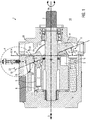
- Fig. 1 shows a pump 1, here an axial piston pump.
- a drive shaft 2 rotates a set of delivery pistons 3, one end of which rests on a swash plate 4 which cannot be rotated and is inclined.
- the conveying movement takes place in the course of the relative rotation between the conveying piston 3 and the swash plate 4.
- the conveying pistons 3 pressed against the swash plate 4 and rotating with the drive shaft move in and out in the axial direction 5 in cylinder 6 and promote this in the fluid contained in the delivery chamber 7.
- the volume flow delivered by the delivery pistons 3 of the pump 1 depends on the inclination 8 of the swash plate 4 relative to a reference plane 9 perpendicular to the axial direction 5.
- the inclination 8 of the swash plate 4 can be changed by one Fig. 1 Axis 8 'perpendicular to the image plane can be adjusted.
- At least one adjusting piston 10, which acts on the swash plate 4 serves to adjust the inclination 8. The more the swash plate 4 is inclined with respect to the reference plane 9, the greater the stroke of the delivery piston 3 in one revolution and thus also the amount of fluid delivered per stroke. If the swash plate 4 is placed vertically, that is to say aligned parallel to the reference plane 9, the delivery pistons 5 are not deflected during one revolution and the delivery volume is zero.
- compensating joints 11 are arranged, which compensate for an inclination-dependent offset in the radial direction 12 between the swash plate 4 and the adjusting piston 10 and a relative pivoting of the swash plate 4 relative to the adjusting piston 10.
- the number of delivery pistons 3 and adjusting pistons 10 varies according to requirements and design.
- the end positions 13, 14 of the inclination 8 of the swash plate 4 can be defined by stops 15, 16, preferably on the housing side. In the end position 14, the swash plate 4 'bears against the stop 15, being oriented perpendicular to the axial direction 5. If the swash plate 4 lies against the stop 16, as shown, it is inclined to the maximum.
- the swash plate 4 can be located in a chamber 17, which is preferably sealed off from a pump environment 18.
- the chamber 17 is surrounded in the radial direction 12 on the outside by a housing wall 19 which is part of a housing 20.
- the housing wall 19 is opposite a peripheral surface or an outer periphery 21 of the swash plate 4.
- a scanning system 22 is provided according to the invention, which has at least one scanning surface 23 and a sensor 24.
- the structure of the scanning system starts Fig. 2 in which the detail "A" of the Fig. 1 is shown enlarged.
- the at least one scanning surface 23 moves with the swash plate 4, while the sensor 24 is arranged stationary on the housing side.
- the scanning surface 23 can in particular how Fig. 1 shows, be arranged on the swash plate 4 and preferably move rigidly with the swash plate 4.
- the scanning surface 23 is arranged in a scanning region 25 of the sensor 24, so that a change in the position of the scanning surface 23 with a changed inclination of the swash plate 4 is detected by the sensor 24.
- the senor 24 outputs an inclination signal 26 representative of the inclination 8.
- the inclination signal 26 can contain the inclination 8 in the form of an electrical, hydraulic or pneumatic signal, analog or digitally coded.
- the slope signal 26 is a hydraulic signal, in which a pressure in a control line (not shown) connected to the sensor represents the slope 8.
- the sensor 24 can work contactlessly, for example inductively, magnetically or optically, or mechanically scan the scanning surface 23.
- a mechanical scanning shows the exemplary embodiment of FIG Fig. 1 and 2nd .
- the sensor 24 accordingly has a scanning head 27 which is pressed against the scanning surface 23 under a pressing force 28.
- the contact pressure 28 is generated by a pneumatic, hydraulic and / or mechanical force transmitter 29, here a spring.
- the scanning head 27 is preferably guided to move exclusively in the radial direction 12 and follows the movement of the scanning surface 23 when the inclination 8 of the swash plate changes and the scanning surface 23 moves with the swash plate 4 in the radial and axial directions.
- the scanning surface 23 is contoured such that with the inclination 8 of the swash plate 4, a distance 30 changes between a section 31 of the housing 20 and the scanning surface 23 in the axially fixed scanning region 25.
- Each inclination 8 of the swash plate 4 is assigned a different distance 30.
- the section 31 can be the section of the housing 20 to which the sensor 24 is attached.
- the housing-side sensor 24 detects the distance 30 by the scanning head 27 following the scanning surface 23 in the radial direction 12 and opening or closing a control valve 32.
- the movement of the scanning head 27 changes a control pressure via the control valve 32, which serves as an inclination signal 26.
- a linear or a non-linear relationship can be established between the inclination 8 of the swash plate and the course of the inclination signal 26.
- the distance 30 can change non-linearly with the inclination 8. This allows a control parameter that is dependent on the inclination angle to be taken into account directly in the inclination signal 26 generated by the scanning surface 23.
- the scanning surface 23 is accessible from the outside in the radial direction 12 and the sensor 24 is arranged to overlap the scanning surface in the radial direction.
- This configuration leads to a compact construction of the pump 1 in the axial direction.
- the sensor 24 requires space in the radial direction.
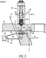
- An alternative design is shown below with reference to Fig. 3 described.
- the at least one scanning surface 23 can be part of at least one separate transmitter element 33, which is preferably repeatedly attached to the swash plate 4 in a releasable manner.
- the encoder element 33 can taper in a wedge shape so that it can follow the movement of the swash plate without requiring a large volume.
- the transmitter element 33 springs out in the axial direction 5 with respect to the swash plate 4, for example in the direction of the adjusting pistons 10 and / or the delivery pistons 3.
- Fig. 3 shows that the at least one transmitter element 33 is a flat body, the narrow sides 34 of which point in the radial direction 12 and the axial direction 5.
- the flat sides 35 point in a circumferential direction 36.
- the transmitter element 33 is inserted into a preferably groove-shaped recess or receptacle 37 of the swash plate 4.
- the receptacle 37 is, for example, an axial groove, the base 38 of which points radially outward.
- the receptacle 37 is open at at least one of its two ends 38 located in the axial direction.
- the at least one transmitter element 33 can also be arranged in the region of a horn 40 of the swash plate 4 projecting outward in the radial direction.
- the scanning surface 23 is protruded toward the outer circumference 21 in the receptacle of wall sections 41 of the swash plate 4.
- the clear width 42 of the receptacle 37 in the circumferential direction 36 is greater than the width 43 of the scanning head 27 in this direction.
- the scanning head 27 of the sensor 24 can consequently move into the receptacle 37 in at least one position of the swash plate 4.
- the receptacle 37 can widen outwards in the radial direction 12. As a result, the scanning head 27 can be received better.
- Fig. 4 shows a further embodiment of the invention. For the sake of brevity, only the differences from the previous exemplary embodiment are discussed. The same reference numerals are used for elements whose structure and / or function correspond to elements already described.
- the sensor 24 is after Fig. 4 arranged in the axial direction 5 overlapping with the scanning surface 23. Such a configuration leads to a smaller space requirement in the radial direction, as the comparison between Fig. 1 and 4th immediately shows.
- the scanning head 27 follows the movement of the scanning surface 23 in the axial direction. Otherwise, the same sensor 24 as in FIG Fig. 1 be used.
- the scanning surface 23 is contoured accordingly such that the inclination-dependent distance 30 now clearly shows the inclination 8 in the axial direction.
- the scanning surface 23 is now freely accessible in the axial direction on the swash plate 4 opposite the housing wall 18.
- the scanning surface 23 is located on an end face 44 of the swash plate pointing in the axial direction 8
- the transmitter element 33 can be inserted into a receptacle 37, which, however, is then preferably designed as a radial groove which can be open at an end 38 located in the radial direction.
- the transmitter element can be arranged in the area of a horn 40 and at least partially sunk in the swash plate.
- the scanning area 23 can be shortened if the scanning head 27 is extended accordingly. This can go so far that the swashplate-side scanning surface is almost punctiform and the scanning head is similar to the scanning surfaces 23 in FIG 1 to 4 is designed.
Landscapes
- Engineering & Computer Science (AREA)
- Mechanical Engineering (AREA)
- General Engineering & Computer Science (AREA)
- Reciprocating Pumps (AREA)
Claims (10)
- Pompe (1) avec au moins un plateau oscillant (4) réglable en inclinaison et au moins un système de palpage (22) pour la détection de l'inclinaison (8) du plateau oscillant (4), le système de palpage (22) présentant au moins un capteur (24) et au moins une surface de palpage (23) disposée de manière à pouvoir être balayée par le capteur (24) et mobile avec le plateau oscillant (4), ladite au moins une surface de palpage (23) se trouvant sur le plateau oscillant (4),
caractérisé en ce que
la surface de palpage (23) est située sur au moins un élément de codage séparé (33) fixé au plateau oscillant (4), et dans lequel l'élément de codage (33) est relié de manière remplaçable au plateau oscillant (4) sans destruction de ce dernier. - Pompe (1) selon la revendication 1, caractérisée en ce que l'élément capteur (36) est en forme de coin.
- Pompe (1) selon les revendications 1 ou 2, caractérisée en ce que l'élément capteur (33) est un corps plat.
- Pompe (1) selon l'une des revendications 1 à 3, caractérisée en ce que l'élément émetteur (33) est inséré dans un réceptacle (37) du plateau oscillant (4).
- Pompe (1) selon la revendication 4, caractérisée en ce que le réceptacle (37) s'élargit en direction du capteur (24).
- Pompe (1) selon l'une des revendications 1 à 5, caractérisée en ce que l'élément de détection (33) est enfoncé au moins par sections dans le plateau oscillant (4).
- Pompe (1) selon l'une des revendications 1 à 6, caractérisée en ce que le capteur (24) fait saillie dans un logement (37) du plateau oscillant (4) dans au moins une position du plateau oscillant (4).
- Pompe (1) selon l'une des revendications 1 à 7, caractérisée en ce que la surface de palpage (23) s'étend en retrait dans le plateau oscillant (4) au moins par sections.
- Pompe (1) selon l'une des revendications 1 à 8, caractérisée en ce que le capteur (24) possède une tête de palpage mobile (27) reposant contre la surface de palpage (23).
- Pompe (1) selon l'une des revendications 1 à 9, caractérisée en ce que la surface de palpage (23) dépasse du plateau oscillant (4) sur un côté faisant face à au moins une pompe d'alimentation (3) et/ou à au moins un piston de réglage (10).
Applications Claiming Priority (2)
| Application Number | Priority Date | Filing Date | Title |
|---|---|---|---|
| DE102012221922.6A DE102012221922A1 (de) | 2012-11-29 | 2012-11-29 | Pumpe, insbesondere Axialkolbenpumpe mit Abtastfläche an der Schrägscheibe |
| PCT/EP2013/073849 WO2014082865A1 (fr) | 2012-11-29 | 2013-11-14 | Pompe, notamment pompe à piston axial munie d'une surface de palpage sur le plateau oscillant |
Publications (2)
| Publication Number | Publication Date |
|---|---|
| EP2926006A1 EP2926006A1 (fr) | 2015-10-07 |
| EP2926006B1 true EP2926006B1 (fr) | 2020-04-29 |
Family
ID=49578318
Family Applications (1)
| Application Number | Title | Priority Date | Filing Date |
|---|---|---|---|
| EP13789586.8A Active EP2926006B1 (fr) | 2012-11-29 | 2013-11-14 | Pompe, notamment pompe à piston axial munie d'une surface de palpage sur le plateau oscillant |
Country Status (3)
| Country | Link |
|---|---|
| EP (1) | EP2926006B1 (fr) |
| DE (1) | DE102012221922A1 (fr) |
| WO (1) | WO2014082865A1 (fr) |
Families Citing this family (5)
| Publication number | Priority date | Publication date | Assignee | Title |
|---|---|---|---|---|
| DE102015205548B4 (de) * | 2015-03-26 | 2017-05-24 | Danfoss Power Solutions Gmbh & Co. Ohg | Endlagendetektion in einer verstellbaren hydraulikmaschine |
| CN109441752A (zh) * | 2018-09-30 | 2019-03-08 | 江苏金陵智造研究院有限公司 | 一种液压伺服控制系统用伺服泵 |
| EP4036403B1 (fr) * | 2021-01-29 | 2023-12-27 | InLine Hydraulik GmbH | Pompe à fluide, système de commande pour une pompe à fluide et procédé de commande d'une pompe à fluide |
| DE102021201409A1 (de) | 2021-02-15 | 2022-08-18 | Robert Bosch Gesellschaft mit beschränkter Haftung | Verdrängermaschine mit einer Messvorrichtung für das Verdrängungsvolumen |
| CN116512597B (zh) * | 2023-06-01 | 2023-11-21 | 昆山市第一人民医院 | 一种3d矫形鞋垫的制作方法、装置 |
Family Cites Families (9)
| Publication number | Priority date | Publication date | Assignee | Title |
|---|---|---|---|---|
| DE2037635A1 (de) * | 1970-07-29 | 1972-02-03 | Robert Bosch Gmbh, 7000 Stuttgart | Verstellbare Axialkolbenmaschine |
| JP3303333B2 (ja) * | 1992-06-09 | 2002-07-22 | 株式会社豊田自動織機 | 可変容量型圧縮機における容量検出装置 |
| DE19608228B4 (de) * | 1996-03-04 | 2006-03-16 | Linde Ag | Hydrostatische Axialkolbenmaschine |
| DE19819960B4 (de) * | 1998-05-05 | 2005-03-03 | Robert Bosch Gmbh | Axialkolbenmaschine mit integriertem Schwenkwegmeßsystem |
| US6848888B2 (en) * | 2002-12-12 | 2005-02-01 | Caterpillar Inc. | Sensor for a variable displacement pump |
| US7275474B2 (en) * | 2005-05-31 | 2007-10-02 | Parker-Hannifincorporation | Optical position sensing and method |
| DE102007022568A1 (de) * | 2007-05-14 | 2008-11-20 | Robert Bosch Gmbh | Niederhaltesegment |
| US8202058B2 (en) * | 2008-08-13 | 2012-06-19 | Sauer-Danfoss Inc. | Variable displacement piston machine with a sensor |
| SE533414C2 (sv) * | 2008-09-17 | 2010-09-21 | Parker Hannifin Ab | Oklägessensor för en hydraulisk anordning |
-
2012
- 2012-11-29 DE DE102012221922.6A patent/DE102012221922A1/de active Pending
-
2013
- 2013-11-14 EP EP13789586.8A patent/EP2926006B1/fr active Active
- 2013-11-14 WO PCT/EP2013/073849 patent/WO2014082865A1/fr not_active Ceased
Non-Patent Citations (1)
| Title |
|---|
| None * |
Also Published As
| Publication number | Publication date |
|---|---|
| WO2014082865A1 (fr) | 2014-06-05 |
| DE102012221922A1 (de) | 2014-06-05 |
| EP2926006A1 (fr) | 2015-10-07 |
Similar Documents
| Publication | Publication Date | Title |
|---|---|---|
| EP2926006B1 (fr) | Pompe, notamment pompe à piston axial munie d'une surface de palpage sur le plateau oscillant | |
| EP2547927B1 (fr) | Ensemble capteur pour un frein à disque | |
| EP3189235B1 (fr) | Pompe à cavité progressive | |
| EP1865204A2 (fr) | Dispositif destiné à la mesure de l'élévation du réglage d'un dispositif de réglage hydraulique | |
| DE102016200234A1 (de) | Schrägscheiben-winkelsensor | |
| EP2145105B1 (fr) | Machine à pistons axiaux | |
| EP2739872A1 (fr) | Cylindre hydraulique destiné en particulier à un dispositif d'actionnement de l'embrayage d'un véhicule automobile | |
| DE102012222172A1 (de) | Axialkolbenmaschine mit kegelförmigem Kolben | |
| EP0181415B1 (fr) | Dispositif de positionnement pour vérin sans tige | |
| EP1901040A2 (fr) | Capteur d'angle de rotation sans contact | |
| DE102017111083B3 (de) | Kupplungsnehmerzylinder mit integrierter Wegmessung | |
| EP1050685B1 (fr) | Glisseur hydraulique linéaire | |
| EP1070856B1 (fr) | Dispositive de détection de la position d'un piston | |
| DE102011118519B4 (de) | Fluidbetätigter Linearantrieb | |
| EP2630396B1 (fr) | Dispositif de détermination de la position pour montage à une vanne et méthode de détermination de la position d'un actuateur | |
| DE19513767B4 (de) | Verstellbare, hydrostatische Radialkolbenmaschine | |
| EP3473898A1 (fr) | Garniture mécanique d'étanchéité destinée à étanchéifier un canal et / ou un espace guidant un fluide | |
| EP4179233B1 (fr) | Dispositif de commande pour une boîte de vitesses automatique | |
| EP3728761A1 (fr) | Mécanisme d'entraînement en rotation hydraulique | |
| EP1691165B1 (fr) | Dispositif destiné à la vérification des tolérances de dimension, de forme et de position d'une pièce mécanique | |
| DE102018101572B3 (de) | Kupplungsausrücker mit relativ zum Kolben bewegbaren Magneten zur Positionserfassung des Kolbens | |
| EP4416393B1 (fr) | Dispositif d'actionnement électrohydraulique à éléments fonctionnels électriques intégrés | |
| EP4323727B1 (fr) | Système électromagnétique de mesure de course d'un piston, support d'aimant ainsi qu'utilisation d'un système électromagnétique de mesure de course d'un piston | |
| DE4434665C2 (de) | Hydraulik-Arbeitszylinder | |
| EP3343182B1 (fr) | Capteur de trajectoire linéaire destiné à détecter un mouvement linéaire d'un objet |
Legal Events
| Date | Code | Title | Description |
|---|---|---|---|
| PUAI | Public reference made under article 153(3) epc to a published international application that has entered the european phase |
Free format text: ORIGINAL CODE: 0009012 |
|
| 17P | Request for examination filed |
Effective date: 20150615 |
|
| AK | Designated contracting states |
Kind code of ref document: A1 Designated state(s): AL AT BE BG CH CY CZ DE DK EE ES FI FR GB GR HR HU IE IS IT LI LT LU LV MC MK MT NL NO PL PT RO RS SE SI SK SM TR |
|
| AX | Request for extension of the european patent |
Extension state: BA ME |
|
| DAX | Request for extension of the european patent (deleted) | ||
| GRAP | Despatch of communication of intention to grant a patent |
Free format text: ORIGINAL CODE: EPIDOSNIGR1 |
|
| STAA | Information on the status of an ep patent application or granted ep patent |
Free format text: STATUS: GRANT OF PATENT IS INTENDED |
|
| INTG | Intention to grant announced |
Effective date: 20200102 |
|
| GRAS | Grant fee paid |
Free format text: ORIGINAL CODE: EPIDOSNIGR3 |
|
| GRAA | (expected) grant |
Free format text: ORIGINAL CODE: 0009210 |
|
| STAA | Information on the status of an ep patent application or granted ep patent |
Free format text: STATUS: THE PATENT HAS BEEN GRANTED |
|
| AK | Designated contracting states |
Kind code of ref document: B1 Designated state(s): AL AT BE BG CH CY CZ DE DK EE ES FI FR GB GR HR HU IE IS IT LI LT LU LV MC MK MT NL NO PL PT RO RS SE SI SK SM TR |
|
| REG | Reference to a national code |
Ref country code: GB Ref legal event code: FG4D Free format text: NOT ENGLISH |
|
| REG | Reference to a national code |
Ref country code: CH Ref legal event code: EP |
|
| REG | Reference to a national code |
Ref country code: DE Ref legal event code: R096 Ref document number: 502013014667 Country of ref document: DE |
|
| REG | Reference to a national code |
Ref country code: AT Ref legal event code: REF Ref document number: 1263711 Country of ref document: AT Kind code of ref document: T Effective date: 20200515 |
|
| REG | Reference to a national code |
Ref country code: IE Ref legal event code: FG4D Free format text: LANGUAGE OF EP DOCUMENT: GERMAN |
|
| REG | Reference to a national code |
Ref country code: NL Ref legal event code: MP Effective date: 20200429 |
|
| REG | Reference to a national code |
Ref country code: LT Ref legal event code: MG4D |
|
| PG25 | Lapsed in a contracting state [announced via postgrant information from national office to epo] |
Ref country code: GR Free format text: LAPSE BECAUSE OF FAILURE TO SUBMIT A TRANSLATION OF THE DESCRIPTION OR TO PAY THE FEE WITHIN THE PRESCRIBED TIME-LIMIT Effective date: 20200730 Ref country code: LT Free format text: LAPSE BECAUSE OF FAILURE TO SUBMIT A TRANSLATION OF THE DESCRIPTION OR TO PAY THE FEE WITHIN THE PRESCRIBED TIME-LIMIT Effective date: 20200429 Ref country code: SE Free format text: LAPSE BECAUSE OF FAILURE TO SUBMIT A TRANSLATION OF THE DESCRIPTION OR TO PAY THE FEE WITHIN THE PRESCRIBED TIME-LIMIT Effective date: 20200429 Ref country code: PT Free format text: LAPSE BECAUSE OF FAILURE TO SUBMIT A TRANSLATION OF THE DESCRIPTION OR TO PAY THE FEE WITHIN THE PRESCRIBED TIME-LIMIT Effective date: 20200831 Ref country code: NO Free format text: LAPSE BECAUSE OF FAILURE TO SUBMIT A TRANSLATION OF THE DESCRIPTION OR TO PAY THE FEE WITHIN THE PRESCRIBED TIME-LIMIT Effective date: 20200729 Ref country code: FI Free format text: LAPSE BECAUSE OF FAILURE TO SUBMIT A TRANSLATION OF THE DESCRIPTION OR TO PAY THE FEE WITHIN THE PRESCRIBED TIME-LIMIT Effective date: 20200429 Ref country code: IS Free format text: LAPSE BECAUSE OF FAILURE TO SUBMIT A TRANSLATION OF THE DESCRIPTION OR TO PAY THE FEE WITHIN THE PRESCRIBED TIME-LIMIT Effective date: 20200829 |
|
| PG25 | Lapsed in a contracting state [announced via postgrant information from national office to epo] |
Ref country code: RS Free format text: LAPSE BECAUSE OF FAILURE TO SUBMIT A TRANSLATION OF THE DESCRIPTION OR TO PAY THE FEE WITHIN THE PRESCRIBED TIME-LIMIT Effective date: 20200429 Ref country code: LV Free format text: LAPSE BECAUSE OF FAILURE TO SUBMIT A TRANSLATION OF THE DESCRIPTION OR TO PAY THE FEE WITHIN THE PRESCRIBED TIME-LIMIT Effective date: 20200429 Ref country code: HR Free format text: LAPSE BECAUSE OF FAILURE TO SUBMIT A TRANSLATION OF THE DESCRIPTION OR TO PAY THE FEE WITHIN THE PRESCRIBED TIME-LIMIT Effective date: 20200429 Ref country code: BG Free format text: LAPSE BECAUSE OF FAILURE TO SUBMIT A TRANSLATION OF THE DESCRIPTION OR TO PAY THE FEE WITHIN THE PRESCRIBED TIME-LIMIT Effective date: 20200729 |
|
| PG25 | Lapsed in a contracting state [announced via postgrant information from national office to epo] |
Ref country code: NL Free format text: LAPSE BECAUSE OF FAILURE TO SUBMIT A TRANSLATION OF THE DESCRIPTION OR TO PAY THE FEE WITHIN THE PRESCRIBED TIME-LIMIT Effective date: 20200429 Ref country code: AL Free format text: LAPSE BECAUSE OF FAILURE TO SUBMIT A TRANSLATION OF THE DESCRIPTION OR TO PAY THE FEE WITHIN THE PRESCRIBED TIME-LIMIT Effective date: 20200429 |
|
| PG25 | Lapsed in a contracting state [announced via postgrant information from national office to epo] |
Ref country code: EE Free format text: LAPSE BECAUSE OF FAILURE TO SUBMIT A TRANSLATION OF THE DESCRIPTION OR TO PAY THE FEE WITHIN THE PRESCRIBED TIME-LIMIT Effective date: 20200429 Ref country code: SM Free format text: LAPSE BECAUSE OF FAILURE TO SUBMIT A TRANSLATION OF THE DESCRIPTION OR TO PAY THE FEE WITHIN THE PRESCRIBED TIME-LIMIT Effective date: 20200429 Ref country code: CZ Free format text: LAPSE BECAUSE OF FAILURE TO SUBMIT A TRANSLATION OF THE DESCRIPTION OR TO PAY THE FEE WITHIN THE PRESCRIBED TIME-LIMIT Effective date: 20200429 Ref country code: RO Free format text: LAPSE BECAUSE OF FAILURE TO SUBMIT A TRANSLATION OF THE DESCRIPTION OR TO PAY THE FEE WITHIN THE PRESCRIBED TIME-LIMIT Effective date: 20200429 Ref country code: IT Free format text: LAPSE BECAUSE OF FAILURE TO SUBMIT A TRANSLATION OF THE DESCRIPTION OR TO PAY THE FEE WITHIN THE PRESCRIBED TIME-LIMIT Effective date: 20200429 Ref country code: ES Free format text: LAPSE BECAUSE OF FAILURE TO SUBMIT A TRANSLATION OF THE DESCRIPTION OR TO PAY THE FEE WITHIN THE PRESCRIBED TIME-LIMIT Effective date: 20200429 Ref country code: DK Free format text: LAPSE BECAUSE OF FAILURE TO SUBMIT A TRANSLATION OF THE DESCRIPTION OR TO PAY THE FEE WITHIN THE PRESCRIBED TIME-LIMIT Effective date: 20200429 |
|
| REG | Reference to a national code |
Ref country code: DE Ref legal event code: R097 Ref document number: 502013014667 Country of ref document: DE |
|
| PG25 | Lapsed in a contracting state [announced via postgrant information from national office to epo] |
Ref country code: PL Free format text: LAPSE BECAUSE OF FAILURE TO SUBMIT A TRANSLATION OF THE DESCRIPTION OR TO PAY THE FEE WITHIN THE PRESCRIBED TIME-LIMIT Effective date: 20200429 Ref country code: SK Free format text: LAPSE BECAUSE OF FAILURE TO SUBMIT A TRANSLATION OF THE DESCRIPTION OR TO PAY THE FEE WITHIN THE PRESCRIBED TIME-LIMIT Effective date: 20200429 |
|
| PLBE | No opposition filed within time limit |
Free format text: ORIGINAL CODE: 0009261 |
|
| STAA | Information on the status of an ep patent application or granted ep patent |
Free format text: STATUS: NO OPPOSITION FILED WITHIN TIME LIMIT |
|
| 26N | No opposition filed |
Effective date: 20210201 |
|
| PG25 | Lapsed in a contracting state [announced via postgrant information from national office to epo] |
Ref country code: SI Free format text: LAPSE BECAUSE OF FAILURE TO SUBMIT A TRANSLATION OF THE DESCRIPTION OR TO PAY THE FEE WITHIN THE PRESCRIBED TIME-LIMIT Effective date: 20200429 |
|
| PG25 | Lapsed in a contracting state [announced via postgrant information from national office to epo] |
Ref country code: MC Free format text: LAPSE BECAUSE OF FAILURE TO SUBMIT A TRANSLATION OF THE DESCRIPTION OR TO PAY THE FEE WITHIN THE PRESCRIBED TIME-LIMIT Effective date: 20200429 |
|
| REG | Reference to a national code |
Ref country code: CH Ref legal event code: PL |
|
| PG25 | Lapsed in a contracting state [announced via postgrant information from national office to epo] |
Ref country code: LU Free format text: LAPSE BECAUSE OF NON-PAYMENT OF DUE FEES Effective date: 20201114 |
|
| REG | Reference to a national code |
Ref country code: BE Ref legal event code: MM Effective date: 20201130 |
|
| PG25 | Lapsed in a contracting state [announced via postgrant information from national office to epo] |
Ref country code: LI Free format text: LAPSE BECAUSE OF NON-PAYMENT OF DUE FEES Effective date: 20201130 Ref country code: CH Free format text: LAPSE BECAUSE OF NON-PAYMENT OF DUE FEES Effective date: 20201130 |
|
| PG25 | Lapsed in a contracting state [announced via postgrant information from national office to epo] |
Ref country code: IE Free format text: LAPSE BECAUSE OF NON-PAYMENT OF DUE FEES Effective date: 20201114 |
|
| REG | Reference to a national code |
Ref country code: AT Ref legal event code: MM01 Ref document number: 1263711 Country of ref document: AT Kind code of ref document: T Effective date: 20201114 |
|
| PG25 | Lapsed in a contracting state [announced via postgrant information from national office to epo] |
Ref country code: AT Free format text: LAPSE BECAUSE OF NON-PAYMENT OF DUE FEES Effective date: 20201114 |
|
| PG25 | Lapsed in a contracting state [announced via postgrant information from national office to epo] |
Ref country code: TR Free format text: LAPSE BECAUSE OF FAILURE TO SUBMIT A TRANSLATION OF THE DESCRIPTION OR TO PAY THE FEE WITHIN THE PRESCRIBED TIME-LIMIT Effective date: 20200429 Ref country code: MT Free format text: LAPSE BECAUSE OF FAILURE TO SUBMIT A TRANSLATION OF THE DESCRIPTION OR TO PAY THE FEE WITHIN THE PRESCRIBED TIME-LIMIT Effective date: 20200429 Ref country code: CY Free format text: LAPSE BECAUSE OF FAILURE TO SUBMIT A TRANSLATION OF THE DESCRIPTION OR TO PAY THE FEE WITHIN THE PRESCRIBED TIME-LIMIT Effective date: 20200429 |
|
| PG25 | Lapsed in a contracting state [announced via postgrant information from national office to epo] |
Ref country code: MK Free format text: LAPSE BECAUSE OF FAILURE TO SUBMIT A TRANSLATION OF THE DESCRIPTION OR TO PAY THE FEE WITHIN THE PRESCRIBED TIME-LIMIT Effective date: 20200429 |
|
| PG25 | Lapsed in a contracting state [announced via postgrant information from national office to epo] |
Ref country code: BE Free format text: LAPSE BECAUSE OF NON-PAYMENT OF DUE FEES Effective date: 20201130 |
|
| PGFP | Annual fee paid to national office [announced via postgrant information from national office to epo] |
Ref country code: DE Payment date: 20251128 Year of fee payment: 13 |
|
| PGFP | Annual fee paid to national office [announced via postgrant information from national office to epo] |
Ref country code: GB Payment date: 20251125 Year of fee payment: 13 |
|
| PGFP | Annual fee paid to national office [announced via postgrant information from national office to epo] |
Ref country code: FR Payment date: 20251128 Year of fee payment: 13 |