EP2926006B1 - Pumpe, insbesondere axialkolbenpumpe mit abtastfläche an der schrägscheibe - Google Patents
Pumpe, insbesondere axialkolbenpumpe mit abtastfläche an der schrägscheibe Download PDFInfo
- Publication number
- EP2926006B1 EP2926006B1 EP13789586.8A EP13789586A EP2926006B1 EP 2926006 B1 EP2926006 B1 EP 2926006B1 EP 13789586 A EP13789586 A EP 13789586A EP 2926006 B1 EP2926006 B1 EP 2926006B1
- Authority
- EP
- European Patent Office
- Prior art keywords
- swash plate
- pump
- scanning
- scanning surface
- sensor
- Prior art date
- Legal status (The legal status is an assumption and is not a legal conclusion. Google has not performed a legal analysis and makes no representation as to the accuracy of the status listed.)
- Active
Links
Images


Classifications
-
- F—MECHANICAL ENGINEERING; LIGHTING; HEATING; WEAPONS; BLASTING
- F04—POSITIVE - DISPLACEMENT MACHINES FOR LIQUIDS; PUMPS FOR LIQUIDS OR ELASTIC FLUIDS
- F04B—POSITIVE-DISPLACEMENT MACHINES FOR LIQUIDS; PUMPS
- F04B1/00—Multi-cylinder machines or pumps characterised by number or arrangement of cylinders
- F04B1/12—Multi-cylinder machines or pumps characterised by number or arrangement of cylinders having cylinder axes coaxial with, or parallel or inclined to, main shaft axis
- F04B1/14—Multi-cylinder machines or pumps characterised by number or arrangement of cylinders having cylinder axes coaxial with, or parallel or inclined to, main shaft axis having stationary cylinders
- F04B1/141—Details or component parts
- F04B1/146—Swash plates; Actuating elements
-
- F—MECHANICAL ENGINEERING; LIGHTING; HEATING; WEAPONS; BLASTING
- F04—POSITIVE - DISPLACEMENT MACHINES FOR LIQUIDS; PUMPS FOR LIQUIDS OR ELASTIC FLUIDS
- F04B—POSITIVE-DISPLACEMENT MACHINES FOR LIQUIDS; PUMPS
- F04B1/00—Multi-cylinder machines or pumps characterised by number or arrangement of cylinders
- F04B1/12—Multi-cylinder machines or pumps characterised by number or arrangement of cylinders having cylinder axes coaxial with, or parallel or inclined to, main shaft axis
- F04B1/20—Multi-cylinder machines or pumps characterised by number or arrangement of cylinders having cylinder axes coaxial with, or parallel or inclined to, main shaft axis having rotary cylinder block
- F04B1/2014—Details or component parts
- F04B1/2078—Swash plates
-
- F—MECHANICAL ENGINEERING; LIGHTING; HEATING; WEAPONS; BLASTING
- F04—POSITIVE - DISPLACEMENT MACHINES FOR LIQUIDS; PUMPS FOR LIQUIDS OR ELASTIC FLUIDS
- F04B—POSITIVE-DISPLACEMENT MACHINES FOR LIQUIDS; PUMPS
- F04B1/00—Multi-cylinder machines or pumps characterised by number or arrangement of cylinders
- F04B1/12—Multi-cylinder machines or pumps characterised by number or arrangement of cylinders having cylinder axes coaxial with, or parallel or inclined to, main shaft axis
- F04B1/26—Control
- F04B1/28—Control of machines or pumps with stationary cylinders
- F04B1/29—Control of machines or pumps with stationary cylinders by varying the relative positions of a swash plate and a cylinder block
-
- F—MECHANICAL ENGINEERING; LIGHTING; HEATING; WEAPONS; BLASTING
- F04—POSITIVE - DISPLACEMENT MACHINES FOR LIQUIDS; PUMPS FOR LIQUIDS OR ELASTIC FLUIDS
- F04B—POSITIVE-DISPLACEMENT MACHINES FOR LIQUIDS; PUMPS
- F04B1/00—Multi-cylinder machines or pumps characterised by number or arrangement of cylinders
- F04B1/12—Multi-cylinder machines or pumps characterised by number or arrangement of cylinders having cylinder axes coaxial with, or parallel or inclined to, main shaft axis
- F04B1/26—Control
- F04B1/30—Control of machines or pumps with rotary cylinder blocks
- F04B1/32—Control of machines or pumps with rotary cylinder blocks by varying the relative positions of a swash plate and a cylinder block
- F04B1/324—Control of machines or pumps with rotary cylinder blocks by varying the relative positions of a swash plate and a cylinder block by changing the inclination of the swash plate
Definitions
- the invention relates to a pump, in particular an axial piston pump, with at least one inclination-adjustable swash plate and at least one scanning system for detecting the angle of inclination, the scanning system having at least one sensor and at least one scanning surface arranged by the sensor and movable with the swash plate.
- An axial piston pump with these features is, for example, the V60N pump from HAWE InLine Hydraulik GmbH.
- the volume flow of the pump is set via the inclination of the swash plate.
- Hydraulically operated adjustment pistons are used to adjust the inclination.
- the inclination of the swash plate is recorded via scanning surfaces on the circumference of the adjusting pistons. The scanning surfaces are scanned by the sensor and are specially contoured in the direction of movement of the adjusting pistons, so that an angle of inclination can be uniquely assigned to each position of the adjusting piston.
- the known scanning system is disadvantageous in two respects: On the one hand, the adjusting pistons are difficult to access, so that a great deal of design effort is required to arrange the sensor close to the scanning surfaces. On the other hand, the conventional scanning system leads to a larger design of the pumps because the pistons have to be extended so that the scanning surfaces can be scanned by the sensor over the entire piston stroke. Especially for pumps with high volume flows, this scanning system leads to unacceptable sizes.
- the at least one scanning surface is located on the swash plate.
- Another advantage is that the inclination of the swash plate is directly detected by the scanning surface located on the swash plate.
- a direct detection of the swash plate inclination is not possible. This is disadvantageous in that the
- Adjusting pistons are articulated on the swash plate and thus a possible, wear-related play in the joint between swash plate and adjusting piston is not taken into account.
- an axial piston machine in which an inclination of the swash plate is measured by means of sensors.
- the DE 43 19 097 A1 shows a displacement detector on an adjustable displacement compressor, in which a measurement of the inclination of the swash plate is carried out via a magnetic system.
- the inclination of the swash plate is measured via a piston and a measuring element protruding into a recess in the piston.
- the inclination of the swash plate is controlled by a control valve.
- the object of the invention is to provide a solution in which the pump can be easily adapted to application-specific requirements.
- the scanning surface is located on at least one separate sensor element attached to the inclined surface, the sensor element being interchangeably connected to the swash plate without destroying it.
- the scanning surface can be located on a radially outward-facing peripheral surface of the swash plate.
- Such an arrangement of the scanning surface enables improved accuracy because the deflection on the outer surface of the swash plate is greatest for a given inclination.
- the scanning surface can alternatively or additionally be located on an end face of the swash plate pointing in the axial direction. With this configuration, access to the scanning surface can take place in the axial direction.
- the transmitter element is designed as a separate component, it can be made from a different material than the swash plate without great effort.
- at least the scanning surface can be made of hardened and preferably ground steel.
- the transmitter element can be wedge-shaped in order to make the best possible use of the space available in the pump in view of the tilting movement of the swash plate.
- the plane in which the transmitter element is wedge-shaped preferably runs parallel to the direction of a drive axis of the pump.
- the transmitter element can be a flat body, so that it fits in the circumferential direction between existing components of the pump, such as adjusting and / or delivery pistons.
- Flat sides of the flat body can point in the circumferential direction, narrow sides in the radial and / or axial direction.
- a flat body in one of these configurations can be installed in conventional pump designs without colliding with existing elements.
- the transmitter element can be inserted into a preferably groove-shaped receptacle of the swash plate.
- the receptacle can preferably widen in the direction of the sensor on and / or beyond the scanning surface in order to allow easier access to the scanning surface.
- the clear width of the scanning area can be greater than the width of a sensor, so that the sensor can move into the receptacle.
- the transmitter element does not protrude from the swash plate.
- the transmitter element or the scanning surface can be sunk into the swash plate at least in sections. If the encoder element does not protrude over the swash plate in the radial direction in this embodiment, a compact design is also possible. In particular, when the donor element is accommodated in a groove of the swash plate, it can be overhanged by the groove in the radial direction.
- the scanning surface is preferably arranged in a chamber of the pump so that it is accessible radially and / or axially from the outside. Accessibility from the outside makes it easier to mount the sensor in the chamber.
- the scanning surface can also face a housing wall and preferably lie directly opposite it, so that the sensor is simply attached to the housing wall.
- the senor can be attached to a housing or a housing wall of the pump in the radial and / or axial direction opposite the scanning surface. It can overlap the scanning surface in the radial and / or axial direction.
- the sensor can be screwed into a housing wall of the pump opposite the scanning surface, or it can be attached in some other way.
- the scanning surface can be spaced differently from a fixed housing point in all different positions of the swash plate at at least one fixed axial and / or radial position.
- the inclination of the swash plate is clearly assigned to the distance between the fixed housing point and the swash plate. This distance can therefore be used to clearly detect the angle of inclination. The distance can change non-linearly with the inclination of the swash plate.
- the scanning surface can be curved.
- a contactless sensor for example an optical, capacitive, magnetic, magnetoresistive, inductive and / or electromagnetic sensor
- a mechanical sensor can also be used.
- the mechanical sensor can have a movable scanning head lying against the scanning surface. With such a configuration, the mechanical sensor can follow the movement of the scanning surface.
- the scanning surface can protrude from the swash plate on the side of the piston.
- the scanning surface can overlap the pistons or pumps in the radial direction.
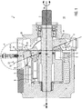
- Fig. 1 shows a pump 1, here an axial piston pump.
- a drive shaft 2 rotates a set of delivery pistons 3, one end of which rests on a swash plate 4 which cannot be rotated and is inclined.
- the conveying movement takes place in the course of the relative rotation between the conveying piston 3 and the swash plate 4.
- the conveying pistons 3 pressed against the swash plate 4 and rotating with the drive shaft move in and out in the axial direction 5 in cylinder 6 and promote this in the fluid contained in the delivery chamber 7.
- the volume flow delivered by the delivery pistons 3 of the pump 1 depends on the inclination 8 of the swash plate 4 relative to a reference plane 9 perpendicular to the axial direction 5.
- the inclination 8 of the swash plate 4 can be changed by one Fig. 1 Axis 8 'perpendicular to the image plane can be adjusted.
- At least one adjusting piston 10, which acts on the swash plate 4 serves to adjust the inclination 8. The more the swash plate 4 is inclined with respect to the reference plane 9, the greater the stroke of the delivery piston 3 in one revolution and thus also the amount of fluid delivered per stroke. If the swash plate 4 is placed vertically, that is to say aligned parallel to the reference plane 9, the delivery pistons 5 are not deflected during one revolution and the delivery volume is zero.
- compensating joints 11 are arranged, which compensate for an inclination-dependent offset in the radial direction 12 between the swash plate 4 and the adjusting piston 10 and a relative pivoting of the swash plate 4 relative to the adjusting piston 10.
- the number of delivery pistons 3 and adjusting pistons 10 varies according to requirements and design.
- the end positions 13, 14 of the inclination 8 of the swash plate 4 can be defined by stops 15, 16, preferably on the housing side. In the end position 14, the swash plate 4 'bears against the stop 15, being oriented perpendicular to the axial direction 5. If the swash plate 4 lies against the stop 16, as shown, it is inclined to the maximum.
- the swash plate 4 can be located in a chamber 17, which is preferably sealed off from a pump environment 18.
- the chamber 17 is surrounded in the radial direction 12 on the outside by a housing wall 19 which is part of a housing 20.
- the housing wall 19 is opposite a peripheral surface or an outer periphery 21 of the swash plate 4.
- a scanning system 22 is provided according to the invention, which has at least one scanning surface 23 and a sensor 24.
- the structure of the scanning system starts Fig. 2 in which the detail "A" of the Fig. 1 is shown enlarged.
- the at least one scanning surface 23 moves with the swash plate 4, while the sensor 24 is arranged stationary on the housing side.
- the scanning surface 23 can in particular how Fig. 1 shows, be arranged on the swash plate 4 and preferably move rigidly with the swash plate 4.
- the scanning surface 23 is arranged in a scanning region 25 of the sensor 24, so that a change in the position of the scanning surface 23 with a changed inclination of the swash plate 4 is detected by the sensor 24.
- the senor 24 outputs an inclination signal 26 representative of the inclination 8.
- the inclination signal 26 can contain the inclination 8 in the form of an electrical, hydraulic or pneumatic signal, analog or digitally coded.
- the slope signal 26 is a hydraulic signal, in which a pressure in a control line (not shown) connected to the sensor represents the slope 8.
- the sensor 24 can work contactlessly, for example inductively, magnetically or optically, or mechanically scan the scanning surface 23.
- a mechanical scanning shows the exemplary embodiment of FIG Fig. 1 and 2nd .
- the sensor 24 accordingly has a scanning head 27 which is pressed against the scanning surface 23 under a pressing force 28.
- the contact pressure 28 is generated by a pneumatic, hydraulic and / or mechanical force transmitter 29, here a spring.
- the scanning head 27 is preferably guided to move exclusively in the radial direction 12 and follows the movement of the scanning surface 23 when the inclination 8 of the swash plate changes and the scanning surface 23 moves with the swash plate 4 in the radial and axial directions.
- the scanning surface 23 is contoured such that with the inclination 8 of the swash plate 4, a distance 30 changes between a section 31 of the housing 20 and the scanning surface 23 in the axially fixed scanning region 25.
- Each inclination 8 of the swash plate 4 is assigned a different distance 30.
- the section 31 can be the section of the housing 20 to which the sensor 24 is attached.
- the housing-side sensor 24 detects the distance 30 by the scanning head 27 following the scanning surface 23 in the radial direction 12 and opening or closing a control valve 32.
- the movement of the scanning head 27 changes a control pressure via the control valve 32, which serves as an inclination signal 26.
- a linear or a non-linear relationship can be established between the inclination 8 of the swash plate and the course of the inclination signal 26.
- the distance 30 can change non-linearly with the inclination 8. This allows a control parameter that is dependent on the inclination angle to be taken into account directly in the inclination signal 26 generated by the scanning surface 23.
- the scanning surface 23 is accessible from the outside in the radial direction 12 and the sensor 24 is arranged to overlap the scanning surface in the radial direction.
- This configuration leads to a compact construction of the pump 1 in the axial direction.
- the sensor 24 requires space in the radial direction.
- An alternative design is shown below with reference to Fig. 3 described.
- the at least one scanning surface 23 can be part of at least one separate transmitter element 33, which is preferably repeatedly attached to the swash plate 4 in a releasable manner.
- the encoder element 33 can taper in a wedge shape so that it can follow the movement of the swash plate without requiring a large volume.
- the transmitter element 33 springs out in the axial direction 5 with respect to the swash plate 4, for example in the direction of the adjusting pistons 10 and / or the delivery pistons 3.
- Fig. 3 shows that the at least one transmitter element 33 is a flat body, the narrow sides 34 of which point in the radial direction 12 and the axial direction 5.
- the flat sides 35 point in a circumferential direction 36.
- the transmitter element 33 is inserted into a preferably groove-shaped recess or receptacle 37 of the swash plate 4.
- the receptacle 37 is, for example, an axial groove, the base 38 of which points radially outward.
- the receptacle 37 is open at at least one of its two ends 38 located in the axial direction.
- the at least one transmitter element 33 can also be arranged in the region of a horn 40 of the swash plate 4 projecting outward in the radial direction.
- the scanning surface 23 is protruded toward the outer circumference 21 in the receptacle of wall sections 41 of the swash plate 4.
- the clear width 42 of the receptacle 37 in the circumferential direction 36 is greater than the width 43 of the scanning head 27 in this direction.
- the scanning head 27 of the sensor 24 can consequently move into the receptacle 37 in at least one position of the swash plate 4.
- the receptacle 37 can widen outwards in the radial direction 12. As a result, the scanning head 27 can be received better.
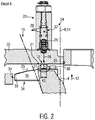
- Fig. 4 shows a further embodiment of the invention. For the sake of brevity, only the differences from the previous exemplary embodiment are discussed. The same reference numerals are used for elements whose structure and / or function correspond to elements already described.
- the sensor 24 is after Fig. 4 arranged in the axial direction 5 overlapping with the scanning surface 23. Such a configuration leads to a smaller space requirement in the radial direction, as the comparison between Fig. 1 and 4th immediately shows.
- the scanning head 27 follows the movement of the scanning surface 23 in the axial direction. Otherwise, the same sensor 24 as in FIG Fig. 1 be used.
- the scanning surface 23 is contoured accordingly such that the inclination-dependent distance 30 now clearly shows the inclination 8 in the axial direction.
- the scanning surface 23 is now freely accessible in the axial direction on the swash plate 4 opposite the housing wall 18.
- the scanning surface 23 is located on an end face 44 of the swash plate pointing in the axial direction 8
- the transmitter element 33 can be inserted into a receptacle 37, which, however, is then preferably designed as a radial groove which can be open at an end 38 located in the radial direction.
- the transmitter element can be arranged in the area of a horn 40 and at least partially sunk in the swash plate.
- the scanning area 23 can be shortened if the scanning head 27 is extended accordingly. This can go so far that the swashplate-side scanning surface is almost punctiform and the scanning head is similar to the scanning surfaces 23 in FIG 1 to 4 is designed.
Landscapes
- Engineering & Computer Science (AREA)
- Mechanical Engineering (AREA)
- General Engineering & Computer Science (AREA)
- Reciprocating Pumps (AREA)
Description
- Die Erfindung betrifft eine Pumpe, insbesondere eine Axialkolbenpumpe, mit wenigstens einer neigungsverstellbaren Schrägscheibe und wenigstens einem Abtastsystem zur Erfassung des Neigungswinkels, wobei das Abtastsystem wenigstens einen Sensor und wenigstens eine vom Sensor abtastbar angeordnete, mit der Schrägscheibe bewegliche Abtastfläche aufweist.
- Eine Axialkolbenpumpe mit diesen Merkmalen ist beispielsweise die Pumpe V60N der HAWE InLine Hydraulik GmbH. Über die Neigung der Schrägscheibe wird der Volumenstrom der Pumpe eingestellt. Zur Neigungsverstellung werden hydraulisch betriebene Verstellkolben eingesetzt. Die Neigung der Schrägscheibe wird über Abtastflächen am Umfang der Verstellkolben erfasst. Die Abtastflächen werden von dem Sensor abgetastet und sind in Bewegungsrichtung der Verstellkolben speziell konturiert, so dass jeder Stellung des Verstellkolbens ein Neigungswinkel eindeutig zugeordnet werden kann.
- Das bekannte Abtastsystem ist in zweierlei Hinsicht nachteilig: Zum einen sind die Verstellkolben schwer zugänglich, so dass ein hoher konstruktiver Aufwand betrieben werden muss, um den Sensor nahe zu den Abtastflächen anzuordnen. Zum anderen führt das herkömmliche Abtastsystem zu einer größeren Bauform der Pumpen, weil die Kolben verlängert werden müssen, damit die Abtastflächen über den gesamten Kolbenhub vom Sensor abgetastet werden können. Insbesondere bei Pumpen mit hohen Volumenströmen führt dieses Abtastsystem zu nicht mehr hinnehmbaren Baugrößen.
- Um eine konstruktiv einfache Pumpe zu schaffen, in der die Neigung der Schrägscheibe erfasst wird und die trotzdem auch bei hohen Volumenströmen klein baut, befindet sich die wenigstens eine Abtastfläche an der Schrägscheibe.
- Dies führt ohne großen konstruktiven Aufwand zu einer gegenüber anderen Pumpen kürzeren Bauform, denn die Verstellkolben müssen nicht verlängert werden, um einen einfachen Zugang zu den Abtastflächen zu erhalten.
- Ein weiterer Vorteil liegt darin, dass durch die sich an der Schrägscheibe befindliche Abtastfläche die Neigung der Schrägscheibe direkt erfasst wird. Bei dem herkömmlichen Abtastsystem, bei dem der Verstellkolben abgetastet wird, ist eine direkte Erfassung der Schrägscheibenneigung nicht möglich. Dies ist insofern von Nachteil, als die
- Verstellkolben an der Schrägscheibe angelenkt sind und somit ein mögliches, verschleißbedingtes Spiel im Gelenk zwischen Schrägscheibe und Verstellkolben nicht berücksichtigt wird.
- Aus der
US 3,733,970 ist eine Axialkolbenmaschine bekannt, bei der mittels Sensoren eine Neigung der Schrägscheibe gemessen wird. DieDE 43 19 097 A1 zeigt einen Verdrängungsdetektor an einem verstellbaren Verdrängungskompressor, bei dem eine Messung der Neigung der Schrägscheibe über ein magnetisches System erfolgt. In derUS 2010/0172766 A1 wird der Neigung der Schrägscheibe über einen Kolben und ein in eine Ausnehmung des Kolbens hineinragendes Messelement gemessen. In derDE 196 08 228 A1 wird die Neigung der Schrägscheibe durch ein Stellventil geregelt. - Aufgabe der Erfindung ist es, eine Lösung bereitzustellen, bei der die Pumpe einfach an anwendungsspezifische Vorgaben angepasst werden kann.
- Gelöst wird diese Aufgabe dadurch, dass sich die Abtastfläche an wenigstens einem separaten, an der Schrägfläche angebrachten Geberelement befindet, wobei das Geberelement ohne Zerstörung der Schrägscheibe austauschbar mit dieser verbunden ist.
- Durch die erfindungsgemäße Lösung können unterschiedlich konturierte Abtastflächen mit einer einzigen Bauform einer Schrägscheibe kombiniert werden. Die in der Pumpe verbaute Abtastfläche lässt sich bei ansonsten unveränderten Komponenten durch einen einfachen Austausch des Geberelements einfach an anwendungsspezifische Vorgaben anpassen.
- Im Folgenden sind weitere, jeweils für sich vorteilhafte und beliebig miteinander kombinierbare Weiterbildungen der Erfindung beschrieben.
- So kann sich gemäß einer ersten vorteilhaften Ausgestaltung die Abtastfläche an einer radial nach außen weisenden Umfangsfläche der Schrägscheibe befinden. Eine solche Anordnung der Abtastfläche ermöglicht eine verbesserte Genauigkeit, weil für eine vorgegebene Neigung die Auslenkung an der Außenfläche der Schrägscheibe am größten ist. Ist der zur Verfügung stehende Raum in radialer Richtung begrenzt, kann sich die Abtastfläche alternativ oder zusätzlich an einer in axiale Richtung weisenden Stirnfläche der Schrägscheibe befinden. Bei dieser Ausgestaltung kann der Zugang zur Abtastfläche in axialer Richtung erfolgen.
- Ist das Geberelement als separates Bauteil ausgestaltet, so kann es ohne großen Aufwand aus einem anderen Material als die Schrägscheibe gefertigt sein. Beispielsweise kann zumindest die Abtastfläche aus einem gehärteten und vorzugsweise geschliffenen Stahl hergestellt sein.
- Das Geberelement kann in einer weiteren Ausgestaltung keilförmig sein, um den in der Pumpe vorhandenen Bauraum in Anbetracht der Kippbewegung der Schrägscheibe möglichst gut zu nutzen. Die Ebene, in der das Geberelement Keilform aufweist, verläuft bevorzugt parallel zur Richtung einer Antriebsachse der Pumpe.
- Das Geberelement kann ein Flachkörper sein, so dass es in Umfangsrichtung zwischen vorhandene Bauelemente der Pumpe wie beispielsweise Verstell- und/oder Förderkolben passt. Flachseiten des Flachkörpers können dabei in Umfangsrichtung, Schmalseiten in radiale und/oder axiale Richtung weisen. Ein Flachkörper in einer dieser Ausgestaltungen lässt sich in herkömmliche Bauformen von Pumpen einbauen, ohne mit bestehenden Elementen zu kollidieren.
- Gemäß einer weiteren vorteilhaften Ausgestaltung kann das Geberelement in eine vorzugsweise nutförmige Aufnahme der Schrägscheibe eingesetzt sein. Dadurch ist eine sichere Befestigung des Geberelements möglich. Die Aufnahme kann sich in Richtung des Sensors vorzugsweise an und/oder jenseits der Abtastfläche weiten, um einen einfacheren Zugang zu der Abtastfläche zu ermöglichen. Insbesondere kann die lichte Weite der Abtastfläche größer sein als die Breite eines Sensors, so dass der Sensor in die Aufnahme einfahren kann.
- Vorteilhaft aufgrund der sich ergebenden Kompaktheit der Pumpe ist ferner, wenn das Geberelement nicht aus der Schrägscheibe ragt. Das Geberelement bzw. die Abtastfläche kann zumindest abschnittsweise in die Schrägscheibe versenkt sein. Wenn das Geberelement bei dieser Ausgestaltung in radialer Richtung nicht über die Schrägscheibe ragt, ist ebenfalls eine kompakte Bauform möglich. Insbesondere kann bei in einer Nut der Schrägscheibe aufgenommenem Geberelement dieses in radialer Richtung von der Nut überragt sein.
- Bevorzugt ist die Abtastfläche von radial und/oder axial außen zugänglich in einer Kammer der Pumpe angeordnet. Die Zugänglichkeit von außen erleichtert die Anbringung des Sensors in der Kammer. Die Abtastfläche kann ferner einer Gehäusewandung zugewandt sein und dieser bevorzugt unmittelbar gegenüber liegen, so dass der Sensor einfach in der Gehäusewandung angebracht wird.
- Der Sensor kann gemäß einer Weiterbildung in radialer und/oder axialer Richtung gegenüberliegend der Abtastfläche an einem Gehäuse oder einer Gehäusewand der Pumpe angebracht sein. Er kann in radialer und/oder axialer Richtung die Abtastfläche überlappen. Der Sensor kann insbesondere in eine Gehäusewand der Pumpe gegenüber der Abtastfläche eingeschraubt oder anderweitig befestigt sein.
- Um eine eindeutige Erfassung des Neigungswinkels sicherzustellen, kann in allen unterschiedlichen Stellungen der Schrägscheibe an wenigstens einer festen axialen und/oder radialen Position die Abtastfläche von einem fixen Gehäusepunkt jeweils unterschiedlich beabstandet sein. Bei einer solchen Ausgestaltung besteht eine eindeutige Zuordnung der Neigung der Schrägscheibe zu dem Abstand zwischen dem fixen Gehäusepunkt und der Schrägscheibe. Dieser Abstand kann folglich zur eindeutigen Erfassung des Neigungswinkels verwendet werden. Der Abstand kann sich nicht-linear mit der Neigung der Schrägscheibe ändern. Die Abtastfläche kann gemäß einer weiteren vorteilhaften Ausgestaltung gekrümmt verlaufen.
- Als Sensor kommt beispielsweise ein berührungslos arbeitender Sensor, beispielsweise ein optischer, kapazitiver, magnetischer, magneto-resistiver, induktiver und/oder elektromagnetischer Sensor in Betracht. Falls jedoch im Betrieb der Bereich zwischen dem Sensor und der Abtastfläche verschmutzt, beispielsweise weil sich an dieser Stelle Metallspäne absetzen, kann auch ein mechanischer Sensor verwendet werden. Der mechanische Sensor kann einen an der Abtastfläche anliegenden, beweglichen Abtastkopf aufweisen. Der mechanische Sensor kann bei einer solchen Ausgestaltung der Bewegung der Abtastfläche folgen.
- Ist gemäß einer weiteren vorteilhaften Ausführungsform an einer in axialer Richtung gelegenen Seite der Schrägscheibe wenigstens ein Förder- und/oder Verstellkolben angeordnet, so kann die Abtastfläche zu der Seite des Kolbens hin von der Schrägscheibe vorspringen. Die Abtastfläche kann hierbei die Kolben bzw. Pumpen in radialer Richtung überlappen. Die Ausgestaltungen führen unabhängig voneinander zu einer kompakten, raumsparenden Bauform.
- Im Folgenden ist die Erfindung anhand von Ausführungsbeispielen exemplarisch mit Bezug auf die beigefügten Zeichnungen näher erläutert.
- Es zeigen:
- Fig. 1
- eine schematische Schnittansicht eines ersten Ausführungsbeispiels einer erfindungsgemäßen Pumpe;
- Fig. 2
- ein Detail "A" der
Fig. 1 ; - Fig. 3
- eine schematische Perspektivdarstellung der Schrägscheibe der Pumpe nach
Fig. 1 ; - Fig. 4
- eine schematische Schnittdarstellung eines weiteren Ausführungsbeispiels einer erfindungsgemäßen Pumpe.
- Zunächst sind Aufbau und Funktion einer erfindungsgemäßen Pumpe mit Bezug auf die
Fig. 1 und2 näher erläutert. -
Fig. 1 zeigt eine Pumpe 1, hier eine Axialkolbenpumpe. Eine Antriebswelle 2 dreht einen Satz von Förderkolben 3, deren eines Ende an einer sich nicht mitdrehenden, neigungsverstellbaren Schrägscheibe 4 anliegt. Die Förderbewegung erfolgt im Zuge der Relativdrehung zwischen den Förderkolben 3 und der Schrägscheibe 4. Bei geneigter Schrägscheibe 4 fahren die gegen die Schrägscheibe 4 gedrückten, sich mit der Antriebswelle drehenden Förderkolben 3 in axialer Richtung 5 in Zylinder 6 ein- und aus und fördern das in der Förderkammer 7 enthaltene Fluid. - Der von den Förderkolben 3 der Pumpe 1 geförderte Volumenstrom hängt von der Neigung 8 der Schrägscheibe 4 gegenüber einer zur axialen Richtung 5 senkrechten Bezugsebene 9 ab. Um die Förderleistung zu verändern, kann die Neigung 8 der Schrägscheibe 4 um eine in
Fig. 1 senkrecht zur Bildebene verlaufende Achse 8' verstellt werden. Zur Verstellung der Neigung 8 dient wenigstens ein Verstellkolben 10, der an der Schrägscheibe 4 angreift. Je mehr die Schrägscheibe 4 gegenüber der Bezugsebene 9 geneigt ist, umso größer ist der Hub der Förderkolben 3 bei einer Umdrehung und somit auch die pro Hub geförderte Fluidmenge. Ist die Schrägscheibe 4 senkrecht gestellt, also parallel zur Bezugsebene 9 ausgerichtet, werden die Förderkolben 5 bei einem Umlauf nicht ausgelenkt und das Fördervolumen ist Null. - Zwischen den Verstellkolben 10 und der Schrägscheibe 4 sind Ausgleichsgelenke 11 angeordnet, die einen neigungsabhängigen Versatz in radialer Richtung 12 zwischen Schrägscheibe 4 und Verstellkolben 10 sowie eine relative Verschwenkung der Schrägscheibe 4 gegenüber den Verstellkolben 10 ausgleichen. Die Anzahl der Förderkolben 3 und Verstellkolben 10 variiert nach Bedarf und Bauform.
- Die Endpositionen 13, 14 der Neigung 8 der Schrägscheibe 4 können durch vorzugsweise gehäuseseitige Anschläge 15, 16 festgelegt sein. In der Endposition 14 liegt die Schrägscheibe 4' am Anschlag 15 an, wobei sie senkrecht zur axialen Richtung 5 ausgerichtet ist. Liegt die Schrägscheibe 4, wie gezeigt, am Anschlag 16 an, ist sie maximal geneigt.
- Die Schrägscheibe 4 kann sich in einer Kammer 17 befinden, die bevorzugt gegenüber einer Pumpenumgebung 18 abgedichtet ist. Die Kammer 17 ist in radialer Richtung 12 außen von einer Gehäusewand 19, die Teil eines Gehäuses 20 ist, umgeben. Die Gehäusewand 19 liegt einer Umfangsfläche bzw. einem Außenumfang 21 der Schrägscheibe 4 gegenüber.
- Um während des Betriebs der Pumpe 1 die Neigung 8 der Schrägscheibe 4 zu erfassen, ist erfindungsgemäß ein Abtastsystem 22 vorgesehen, das wenigstens eine Abtastfläche 23 und einen Sensor 24 aufweist. Der Aufbau des Abtastsystems geht aus
Fig. 2 hervor, in der das Detail "A" derFig. 1 vergrößert wiedergegeben ist. - Die wenigstens eine Abtastfläche 23 bewegt sich mit der Schrägscheibe 4 mit, während der Sensor 24 gehäuseseitig stationär angeordnet ist. Die Abtastfläche 23 kann insbesondere, wie
Fig. 1 zeigt, an der Schrägscheibe 4 angeordnet sein und sich vorzugsweise bewegungsstarr mit der Schrägscheibe 4 mitbewegen. Die Abtastfläche 23 ist in einem Abtastbereich 25 des Sensors 24 angeordnet, so dass eine Lageveränderung der Abtastfläche 23 bei einer veränderten Neigung der Schrägscheibe 4 vom Sensor 24 erfasst wird. - Im Betrieb gibt der Sensor 24 ein für die Neigung 8 repräsentatives Neigungssignal 26 aus. Das Neigungssignal 26 kann die Neigung 8 in Form eines elektrischen, hydraulischen oder pneumatischen Signals analog oder digital kodiert enthalten. Bei der dargestellten Ausführungsform ist das Neigungssignal 26 ein hydraulisches Signal, bei dem ein Druck in einer an den Sensor angeschlossenen Steuerleitung (nicht gezeigt) die Neigung 8 repräsentiert.
- Der Sensor 24 kann berührungslos, beispielsweise induktiv, magnetisch oder optisch, arbeiten, oder die Abtastfläche 23 mechanisch abtasten. Eine solche mechanische Abtastung zeigt beispielhaft das Ausführungsbeispiel der
Fig. 1 und2 . Der Sensor 24 weist demnach einen Abtastkopf 27 auf, der unter einer Anpresskraft 28 gegen die Abtastfläche 23 gedrückt ist. Die Anpresskraft 28 wird von einem pneumatischen, hydraulischen und/oder mechanischen Kraftgeber 29, hier einer Feder, erzeugt. - Der Abtastkopf 27 ist vorzugsweise ausschließlich in radialer Richtung 12 beweglich geführt und folgt der Bewegung der Abtastfläche 23, wenn sich die Neigung 8 der Schrägscheibe ändert und sich die Abtastfläche 23 mit der Schrägscheibe 4 in radialer und axialer Richtung bewegt. Die Abtastfläche 23 ist so konturiert, dass sich mit der Neigung 8 der Schrägscheibe 4 ein Abstand 30 zwischen einem Abschnitt 31 des Gehäuses 20 und der Abtastfläche 23 im axial feststehenden Abtastbereich 25 ändert. Jeder Neigung 8 der Schrägscheibe 4 ist dabei ein anderer Abstand 30 zugeordnet. Der Abschnitt 31 kann derjenige Abschnitt des Gehäuses 20 sein, an dem der Sensor 24 angebracht ist.
- Der gehäuseseitige Sensor 24 erfasst den Abstand 30, indem der Abtastkopf 27 der Abtastfläche 23 in radialer Richtung 12 folgt und ein Steuerventil 32 öffnet oder schließt. Die Bewegung des Abtastkopfes 27 verändert über das Steuerventil 32 einen Steuerdruck, der als Neigungssignal 26 dient.
- Je nach Verlauf der Abtastfläche 23 in Neigungsrichtung kann ein linearer oder ein nichtlinearer Zusammenhang zwischen der Neigung 8 der Schrägscheibe und dem Verlauf des Neigungssignals 26 hergestellt werden. Beispielsweise kann sich der Abstand 30 nicht-linear mit der Neigung 8 verändern. Dies erlaubt es, einen neigungswinkelabhängigen Steuerparameter unmittelbar in dem von der Abtastfläche 23 erzeugten Neigungssignal 26 zu berücksichtigen.
- Beim dargestellten Ausführungsbeispiel ist die Abtastfläche 23 in radialer Richtung 12 von außen zugänglich und der Sensor 24 in radialer Richtung überlappend mit der Abtastfläche angeordnet. Diese Ausgestaltung führt in axialer Richtung zu einer kompakten Bauweise der Pumpe 1. Der Sensor 24 erfordert jedoch Platz in radialer Richtung. Eine alternative Bauform ist weiter unten mit Bezug auf
Fig. 3 beschrieben. - Die wenigstens eine Abtastfläche 23 kann Teil wenigstens eines separaten Geberelements 33 sein, das bevorzugt wiederholt lösbar an der Schrägscheibe 4 angebracht ist. Das Geberelement 33 kann keilförmig zulaufen, so dass es ohne großen Volumenbedarf der Bewegung der Schrägscheibe folgen kann.
- Das Geberelement 33 springt in axialer Richtung 5 gegenüber der Schrägscheibe 4 hervor, beispielsweise in Richtung der Verstellkolben 10 und/oder der Förderkolben 3.
-
Fig. 3 zeigt, dass das wenigstens eine Geberelement 33 ein Flachkörper ist, dessen Schmalseiten 34 in radiale Richtung 12 und axiale Richtung 5 weisen. Die Flachseiten 35 weisen in eine Umfangsrichtung 36. - Das Geberelement 33 ist in eine vorzugsweise nutförmige Ausnehmung bzw. Aufnahme 37 der Schrägscheibe 4 eingesetzt. Bei einer radialen Abtastung der Abtastfläche ist die Aufnahme 37 beispielsweise eine Axialnut, deren Grund 38 radial nach außen weist. Die Aufnahme 37 ist an wenigstens einem ihrer beiden in axialer Richtung gelegenen Enden 38 offen.
- Das wenigstens eine Geberelement 33 kann ferner im Bereich eines in radialer Richtung nach außen vorspringenden Horns 40 der Schrägscheibe 4 angeordnet sein.
- Die Abtastfläche 23 wird in der Aufnahme von Wandabschnitten 41 der Schrägscheibe 4 zum Außenumfang 21 hin überragt.
- Die lichte Weite 42 der Aufnahme 37 in Umfangsrichtung 36 ist größer als die Breite 43 des Abtastkopfes 27 in dieser Richtung. Der Abtastkopf 27 des Sensors 24 kann folglich in wenigstens einer Stellung der Schrägscheibe 4 in die Aufnahme 37 einfahren. Die Aufnahme 37 kann sich in radialer Richtung 12 nach außen weiten. Dadurch kann der Abtastkopf 27 besser aufgenommen werden.
-
Fig. 4 zeigt ein weiteres Ausführungsbeispiel der Erfindung. Der Kürze halber wird lediglich auf die Unterschiede zum vorangegangenen Ausführungsbeispiel eingegangen. Für Elemente, deren Aufbau und/oder Funktion bereits beschriebenen Elementen entsprechen, sind dieselben Bezugszeichen verwendet. - Der Sensor 24 ist nach
Fig. 4 in axialer Richtung 5 mit der Abtastfläche 23 überlappend angeordnet. Eine solche Ausgestaltung führt in radialer Richtung zu einem geringeren Raumbedarf, wie der Vergleich zwischenFig. 1 und4 unmittelbar zeigt. - Der Abtastkopf 27 folgt bei dieser Ausgestaltung der Bewegung der Abtastfläche 23 in axialer Richtung. Im Übrigen kann der gleiche Sensor 24 wie in
Fig. 1 verwendet werden. Die Abtastfläche 23 ist bei dieser Variante entsprechend so konturiert, dass der neigungsabhängige Abstand 30 nunmehr in axialer Richtung die Neigung 8 eindeutig wiedergibt. Die Abtastfläche 23 ist nunmehr in axialer Richtung frei zugänglich an der Schrägscheibe 4 gegenüber der Gehäusewand 18 angeordnet. Die Abtastfläche 23 befindet sich an einer in axialer Richtung 8 weisenden Stirnfläche 44 der Schrägscheibe - Auch bei dieser Ausgestaltung kann das Geberelement 33 in eine Aufnahme 37 eingesetzt sein, die dann allerdings bevorzugt als eine Radialnut ausgestaltet ist, die an einem in radialer Richtung gelegenen Ende 38 offen sein kann. Das Geberelement kann auch hier im Bereich eines Horns 40 angeordnet und in der Schrägscheibe zumindest abschnittsweise versenkt sein.
- Weitere Abwandlungen des oben beschriebenen Aufbaus sind möglich. So kann die Abtastfläche 23 verkürzt werden, wenn der Abtastkopf 27 entsprechend verlängert wird. Dies kann soweit gehen, dass die schrägscheibenseitige Abtastfläche nahezu punktförmig ist und der Abtastkopf ähnlich den Abtastflächen 23 der
Fig. 1 bis 4 ausgestaltet ist. -
- 1
- Pumpe
- 2
- Antriebswelle
- 3
- Förderkolben
- 4
- Schrägscheibe
- 5
- axiale Richtung
- 6
- Zylinder
- 7
- Förderkammer
- 8
- Neigung
- 8'
- Achse
- 9
- Bezugsebene
- 10
- Verstellkolben
- 11
- Ausgleichsgelenke
- 12
- radiale Richtung
- 13
- erste Endposition der Neigungsverstellung
- 14
- zweite Endposition der Neigungsverstellung
- 15
- Anschlag
- 16
- Anschlag
- 17
- Kammer
- 18
- Umgebung
- 19
- Gehäusewand
- 20
- Gehäuse
- 21
- Außenumfang der Schrägscheibe
- 22
- Abtastsystem
- 23
- Abtastfläche
- 24
- Sensor
- 25
- Abtastbereich
- 26
- Neigungssignal
- 27
- Abtastkopf
- 28
- Anpresskraft
- 29
- Kraftgeber
- 30
- Abstand
- 31
- Abschnitt der Gehäusewand
- 32
- Steuerventil
- 33
- Geberelement
- 34
- Schmalseiten
- 35
- Flachseiten
- 36
- Umfangsrichtung
- 37
- Aufnahme
- 38
- Grund
- 39
- axiale Enden der Aufnahme
- 40
- Horn der Schrägscheibe
- 41
- Wandabschnitte
- 42
- lichte Weite der Aufnahme
- 43
- Breite des Abtastkopfes
- 44
- Stirnfläche der Schrägscheibe
Claims (10)
- Pumpe (1), mit wenigstens einer neigungsverstellbaren Schrägscheibe (4) und wenigstens einem Abtastsystem (22) zur Erfassung der Neigung (8) der Schrägscheibe (4), wobei das Abtastsystem (22) wenigstens einen Sensor (24) und wenigstens eine vom Sensor (24) abtastbar angeordnete, mit der Schrägscheibe (4) bewegliche Abtastfläche (23) aufweist, wobei sich die wenigstens eine Abtastfläche (23) an der Schrägscheibe (4) befindet, dadurch gekennzeichnet, dass sich die Abtastfläche (23) an wenigstens einem separaten, an der Schrägscheibe (4) angebrachten Geberelement (33) befindet, und wobei das Geberelement (33) ohne Zerstörung der Schrägscheibe (4) austauschbar mit dieser verbunden ist.
- Pumpe (1) nach Anspruch 1, dadurch gekennzeichnet, dass das Geberelement (36) keilförmig ist.
- Pumpe (1) nach Anspruch 1 oder 2, dadurch gekennzeichnet, dass das Geberelement (33) ein Flachkörper ist.
- Pumpe (1) nach einem der Ansprüche 1 bis 3, dadurch gekennzeichnet, dass das Geberelement (33) in eine Aufnahme (37) der Schrägscheibe (4) eingesetzt ist.
- Pumpe (1) nach Anspruch 4, dadurch gekennzeichnet, dass die Aufnahme (37) sich in Richtung des Sensors (24) weitet.
- Pumpe (1) nach einem der Ansprüche 1 bis 5, dadurch gekennzeichnet, dass das Geberelement (33) zumindest abschnittsweise in der Schrägscheibe (4) versenkt ist.
- Pumpe (1) nach einem der Ansprüche 1 bis 6, dadurch gekennzeichnet, dass der Sensor (24) in wenigstens einer Stellung der Schrägscheibe (4) in eine Aufnahme (37) der Schrägscheibe (4) ragt.
- Pumpe (1) nach einem der Ansprüche 1 bis 7, dadurch gekennzeichnet, dass die Abtastfläche (23) wenigstens abschnittsweise in der Schrägscheibe (4) versenkt verläuft.
- Pumpe (1) nach einem der Ansprüche 1 bis 8, dadurch gekennzeichnet, dass der Sensor (24) einen an der Abtastfläche (23) anliegenden, beweglichen Abtastkopf (27) aufweist.
- Pumpe (1) nach einem der Ansprüche 1 bis 9, dadurch gekennzeichnet, dass die Abtastfläche (23) auf einer wenigstens einer Förderpumpe (3) und/oder wenigstens einer Verstellkolben (10) zugewandten Seite von der Schrägscheibe (4) vorspringt.
Applications Claiming Priority (2)
| Application Number | Priority Date | Filing Date | Title |
|---|---|---|---|
| DE102012221922.6A DE102012221922A1 (de) | 2012-11-29 | 2012-11-29 | Pumpe, insbesondere Axialkolbenpumpe mit Abtastfläche an der Schrägscheibe |
| PCT/EP2013/073849 WO2014082865A1 (de) | 2012-11-29 | 2013-11-14 | Pumpe, insbesondere axialkolbenpumpe mit abtastfläche an der schrägscheibe |
Publications (2)
| Publication Number | Publication Date |
|---|---|
| EP2926006A1 EP2926006A1 (de) | 2015-10-07 |
| EP2926006B1 true EP2926006B1 (de) | 2020-04-29 |
Family
ID=49578318
Family Applications (1)
| Application Number | Title | Priority Date | Filing Date |
|---|---|---|---|
| EP13789586.8A Active EP2926006B1 (de) | 2012-11-29 | 2013-11-14 | Pumpe, insbesondere axialkolbenpumpe mit abtastfläche an der schrägscheibe |
Country Status (3)
| Country | Link |
|---|---|
| EP (1) | EP2926006B1 (de) |
| DE (1) | DE102012221922A1 (de) |
| WO (1) | WO2014082865A1 (de) |
Families Citing this family (5)
| Publication number | Priority date | Publication date | Assignee | Title |
|---|---|---|---|---|
| DE102015205548B4 (de) * | 2015-03-26 | 2017-05-24 | Danfoss Power Solutions Gmbh & Co. Ohg | Endlagendetektion in einer verstellbaren hydraulikmaschine |
| CN109441752A (zh) * | 2018-09-30 | 2019-03-08 | 江苏金陵智造研究院有限公司 | 一种液压伺服控制系统用伺服泵 |
| EP4036403B1 (de) * | 2021-01-29 | 2023-12-27 | InLine Hydraulik GmbH | Fluidpumpe, steuerungssystem für eine fluidpumpe, und verfahren zum steuern einer fluidpumpe |
| DE102021201409A1 (de) | 2021-02-15 | 2022-08-18 | Robert Bosch Gesellschaft mit beschränkter Haftung | Verdrängermaschine mit einer Messvorrichtung für das Verdrängungsvolumen |
| CN116512597B (zh) * | 2023-06-01 | 2023-11-21 | 昆山市第一人民医院 | 一种3d矫形鞋垫的制作方法、装置 |
Family Cites Families (9)
| Publication number | Priority date | Publication date | Assignee | Title |
|---|---|---|---|---|
| DE2037635A1 (de) * | 1970-07-29 | 1972-02-03 | Robert Bosch Gmbh, 7000 Stuttgart | Verstellbare Axialkolbenmaschine |
| JP3303333B2 (ja) * | 1992-06-09 | 2002-07-22 | 株式会社豊田自動織機 | 可変容量型圧縮機における容量検出装置 |
| DE19608228B4 (de) * | 1996-03-04 | 2006-03-16 | Linde Ag | Hydrostatische Axialkolbenmaschine |
| DE19819960B4 (de) * | 1998-05-05 | 2005-03-03 | Robert Bosch Gmbh | Axialkolbenmaschine mit integriertem Schwenkwegmeßsystem |
| US6848888B2 (en) * | 2002-12-12 | 2005-02-01 | Caterpillar Inc. | Sensor for a variable displacement pump |
| US7275474B2 (en) * | 2005-05-31 | 2007-10-02 | Parker-Hannifincorporation | Optical position sensing and method |
| DE102007022568A1 (de) * | 2007-05-14 | 2008-11-20 | Robert Bosch Gmbh | Niederhaltesegment |
| US8202058B2 (en) * | 2008-08-13 | 2012-06-19 | Sauer-Danfoss Inc. | Variable displacement piston machine with a sensor |
| SE533414C2 (sv) * | 2008-09-17 | 2010-09-21 | Parker Hannifin Ab | Oklägessensor för en hydraulisk anordning |
-
2012
- 2012-11-29 DE DE102012221922.6A patent/DE102012221922A1/de active Pending
-
2013
- 2013-11-14 EP EP13789586.8A patent/EP2926006B1/de active Active
- 2013-11-14 WO PCT/EP2013/073849 patent/WO2014082865A1/de not_active Ceased
Non-Patent Citations (1)
| Title |
|---|
| None * |
Also Published As
| Publication number | Publication date |
|---|---|
| WO2014082865A1 (de) | 2014-06-05 |
| DE102012221922A1 (de) | 2014-06-05 |
| EP2926006A1 (de) | 2015-10-07 |
Similar Documents
| Publication | Publication Date | Title |
|---|---|---|
| EP2926006B1 (de) | Pumpe, insbesondere axialkolbenpumpe mit abtastfläche an der schrägscheibe | |
| EP2547927B1 (de) | Sensoreinheit für eine scheibenbremse | |
| EP3189235B1 (de) | Exzenterschneckenpumpe | |
| EP1865204A2 (de) | Vorrichtung zur Messung des Verstellhubes einer hydraulischen Verstelleinrichtung | |
| DE102016200234A1 (de) | Schrägscheiben-winkelsensor | |
| EP2145105B1 (de) | Axialkolbenmaschine | |
| EP2739872A1 (de) | Hydraulikzylinder, insbesondere für eine kupplungsbetätigungseinrichtung in einem kraftfahrzeug | |
| DE102012222172A1 (de) | Axialkolbenmaschine mit kegelförmigem Kolben | |
| EP0181415B1 (de) | Positioniereinrichtung für kolbenstangenlose Zylinder | |
| EP1901040A2 (de) | Berührungsloser Drehwinkelsensor | |
| DE102017111083B3 (de) | Kupplungsnehmerzylinder mit integrierter Wegmessung | |
| EP1050685B1 (de) | Hydraulischer Linearwegschieber | |
| EP1070856B1 (de) | Vorrichtung zur Erfassung der Lage eines Kolbens | |
| DE102011118519B4 (de) | Fluidbetätigter Linearantrieb | |
| EP2630396B1 (de) | Elektrische stellungsermittlungsvorrichtung zum anbau an ein ventil und verfahren zur ermittlung der position eines stellmittels | |
| DE19513767B4 (de) | Verstellbare, hydrostatische Radialkolbenmaschine | |
| EP3473898A1 (de) | Gleitringdichtung zur abdichtung eines ein fluid führenden kanals und/oder raumes | |
| EP4179233B1 (de) | Betätigungsvorrichtung für ein automatisiertes schaltgetriebe | |
| EP3728761A1 (de) | Hydraulischer drehantrieb | |
| EP1691165B1 (de) | Vorrichtung zur Ueberprüfung der Mass-, Form- und Lagetoleranzen eines mechanischen Werkstueckes | |
| DE102018101572B3 (de) | Kupplungsausrücker mit relativ zum Kolben bewegbaren Magneten zur Positionserfassung des Kolbens | |
| EP4416393B1 (de) | Elektrohydraulische betätigungsvorrichtung mit integrierten elektrischen funktionselementen | |
| EP4323727B1 (de) | Elektromagnetisches hubmesssystem, magnethalter sowie verwendung eines elektromagnetischen hubmesssystems | |
| DE4434665C2 (de) | Hydraulik-Arbeitszylinder | |
| EP3343182B1 (de) | Linearwegsensor zum erfassen einer linearbewegung eines gegenstands |
Legal Events
| Date | Code | Title | Description |
|---|---|---|---|
| PUAI | Public reference made under article 153(3) epc to a published international application that has entered the european phase |
Free format text: ORIGINAL CODE: 0009012 |
|
| 17P | Request for examination filed |
Effective date: 20150615 |
|
| AK | Designated contracting states |
Kind code of ref document: A1 Designated state(s): AL AT BE BG CH CY CZ DE DK EE ES FI FR GB GR HR HU IE IS IT LI LT LU LV MC MK MT NL NO PL PT RO RS SE SI SK SM TR |
|
| AX | Request for extension of the european patent |
Extension state: BA ME |
|
| DAX | Request for extension of the european patent (deleted) | ||
| GRAP | Despatch of communication of intention to grant a patent |
Free format text: ORIGINAL CODE: EPIDOSNIGR1 |
|
| STAA | Information on the status of an ep patent application or granted ep patent |
Free format text: STATUS: GRANT OF PATENT IS INTENDED |
|
| INTG | Intention to grant announced |
Effective date: 20200102 |
|
| GRAS | Grant fee paid |
Free format text: ORIGINAL CODE: EPIDOSNIGR3 |
|
| GRAA | (expected) grant |
Free format text: ORIGINAL CODE: 0009210 |
|
| STAA | Information on the status of an ep patent application or granted ep patent |
Free format text: STATUS: THE PATENT HAS BEEN GRANTED |
|
| AK | Designated contracting states |
Kind code of ref document: B1 Designated state(s): AL AT BE BG CH CY CZ DE DK EE ES FI FR GB GR HR HU IE IS IT LI LT LU LV MC MK MT NL NO PL PT RO RS SE SI SK SM TR |
|
| REG | Reference to a national code |
Ref country code: GB Ref legal event code: FG4D Free format text: NOT ENGLISH |
|
| REG | Reference to a national code |
Ref country code: CH Ref legal event code: EP |
|
| REG | Reference to a national code |
Ref country code: DE Ref legal event code: R096 Ref document number: 502013014667 Country of ref document: DE |
|
| REG | Reference to a national code |
Ref country code: AT Ref legal event code: REF Ref document number: 1263711 Country of ref document: AT Kind code of ref document: T Effective date: 20200515 |
|
| REG | Reference to a national code |
Ref country code: IE Ref legal event code: FG4D Free format text: LANGUAGE OF EP DOCUMENT: GERMAN |
|
| REG | Reference to a national code |
Ref country code: NL Ref legal event code: MP Effective date: 20200429 |
|
| REG | Reference to a national code |
Ref country code: LT Ref legal event code: MG4D |
|
| PG25 | Lapsed in a contracting state [announced via postgrant information from national office to epo] |
Ref country code: GR Free format text: LAPSE BECAUSE OF FAILURE TO SUBMIT A TRANSLATION OF THE DESCRIPTION OR TO PAY THE FEE WITHIN THE PRESCRIBED TIME-LIMIT Effective date: 20200730 Ref country code: LT Free format text: LAPSE BECAUSE OF FAILURE TO SUBMIT A TRANSLATION OF THE DESCRIPTION OR TO PAY THE FEE WITHIN THE PRESCRIBED TIME-LIMIT Effective date: 20200429 Ref country code: SE Free format text: LAPSE BECAUSE OF FAILURE TO SUBMIT A TRANSLATION OF THE DESCRIPTION OR TO PAY THE FEE WITHIN THE PRESCRIBED TIME-LIMIT Effective date: 20200429 Ref country code: PT Free format text: LAPSE BECAUSE OF FAILURE TO SUBMIT A TRANSLATION OF THE DESCRIPTION OR TO PAY THE FEE WITHIN THE PRESCRIBED TIME-LIMIT Effective date: 20200831 Ref country code: NO Free format text: LAPSE BECAUSE OF FAILURE TO SUBMIT A TRANSLATION OF THE DESCRIPTION OR TO PAY THE FEE WITHIN THE PRESCRIBED TIME-LIMIT Effective date: 20200729 Ref country code: FI Free format text: LAPSE BECAUSE OF FAILURE TO SUBMIT A TRANSLATION OF THE DESCRIPTION OR TO PAY THE FEE WITHIN THE PRESCRIBED TIME-LIMIT Effective date: 20200429 Ref country code: IS Free format text: LAPSE BECAUSE OF FAILURE TO SUBMIT A TRANSLATION OF THE DESCRIPTION OR TO PAY THE FEE WITHIN THE PRESCRIBED TIME-LIMIT Effective date: 20200829 |
|
| PG25 | Lapsed in a contracting state [announced via postgrant information from national office to epo] |
Ref country code: RS Free format text: LAPSE BECAUSE OF FAILURE TO SUBMIT A TRANSLATION OF THE DESCRIPTION OR TO PAY THE FEE WITHIN THE PRESCRIBED TIME-LIMIT Effective date: 20200429 Ref country code: LV Free format text: LAPSE BECAUSE OF FAILURE TO SUBMIT A TRANSLATION OF THE DESCRIPTION OR TO PAY THE FEE WITHIN THE PRESCRIBED TIME-LIMIT Effective date: 20200429 Ref country code: HR Free format text: LAPSE BECAUSE OF FAILURE TO SUBMIT A TRANSLATION OF THE DESCRIPTION OR TO PAY THE FEE WITHIN THE PRESCRIBED TIME-LIMIT Effective date: 20200429 Ref country code: BG Free format text: LAPSE BECAUSE OF FAILURE TO SUBMIT A TRANSLATION OF THE DESCRIPTION OR TO PAY THE FEE WITHIN THE PRESCRIBED TIME-LIMIT Effective date: 20200729 |
|
| PG25 | Lapsed in a contracting state [announced via postgrant information from national office to epo] |
Ref country code: NL Free format text: LAPSE BECAUSE OF FAILURE TO SUBMIT A TRANSLATION OF THE DESCRIPTION OR TO PAY THE FEE WITHIN THE PRESCRIBED TIME-LIMIT Effective date: 20200429 Ref country code: AL Free format text: LAPSE BECAUSE OF FAILURE TO SUBMIT A TRANSLATION OF THE DESCRIPTION OR TO PAY THE FEE WITHIN THE PRESCRIBED TIME-LIMIT Effective date: 20200429 |
|
| PG25 | Lapsed in a contracting state [announced via postgrant information from national office to epo] |
Ref country code: EE Free format text: LAPSE BECAUSE OF FAILURE TO SUBMIT A TRANSLATION OF THE DESCRIPTION OR TO PAY THE FEE WITHIN THE PRESCRIBED TIME-LIMIT Effective date: 20200429 Ref country code: SM Free format text: LAPSE BECAUSE OF FAILURE TO SUBMIT A TRANSLATION OF THE DESCRIPTION OR TO PAY THE FEE WITHIN THE PRESCRIBED TIME-LIMIT Effective date: 20200429 Ref country code: CZ Free format text: LAPSE BECAUSE OF FAILURE TO SUBMIT A TRANSLATION OF THE DESCRIPTION OR TO PAY THE FEE WITHIN THE PRESCRIBED TIME-LIMIT Effective date: 20200429 Ref country code: RO Free format text: LAPSE BECAUSE OF FAILURE TO SUBMIT A TRANSLATION OF THE DESCRIPTION OR TO PAY THE FEE WITHIN THE PRESCRIBED TIME-LIMIT Effective date: 20200429 Ref country code: IT Free format text: LAPSE BECAUSE OF FAILURE TO SUBMIT A TRANSLATION OF THE DESCRIPTION OR TO PAY THE FEE WITHIN THE PRESCRIBED TIME-LIMIT Effective date: 20200429 Ref country code: ES Free format text: LAPSE BECAUSE OF FAILURE TO SUBMIT A TRANSLATION OF THE DESCRIPTION OR TO PAY THE FEE WITHIN THE PRESCRIBED TIME-LIMIT Effective date: 20200429 Ref country code: DK Free format text: LAPSE BECAUSE OF FAILURE TO SUBMIT A TRANSLATION OF THE DESCRIPTION OR TO PAY THE FEE WITHIN THE PRESCRIBED TIME-LIMIT Effective date: 20200429 |
|
| REG | Reference to a national code |
Ref country code: DE Ref legal event code: R097 Ref document number: 502013014667 Country of ref document: DE |
|
| PG25 | Lapsed in a contracting state [announced via postgrant information from national office to epo] |
Ref country code: PL Free format text: LAPSE BECAUSE OF FAILURE TO SUBMIT A TRANSLATION OF THE DESCRIPTION OR TO PAY THE FEE WITHIN THE PRESCRIBED TIME-LIMIT Effective date: 20200429 Ref country code: SK Free format text: LAPSE BECAUSE OF FAILURE TO SUBMIT A TRANSLATION OF THE DESCRIPTION OR TO PAY THE FEE WITHIN THE PRESCRIBED TIME-LIMIT Effective date: 20200429 |
|
| PLBE | No opposition filed within time limit |
Free format text: ORIGINAL CODE: 0009261 |
|
| STAA | Information on the status of an ep patent application or granted ep patent |
Free format text: STATUS: NO OPPOSITION FILED WITHIN TIME LIMIT |
|
| 26N | No opposition filed |
Effective date: 20210201 |
|
| PG25 | Lapsed in a contracting state [announced via postgrant information from national office to epo] |
Ref country code: SI Free format text: LAPSE BECAUSE OF FAILURE TO SUBMIT A TRANSLATION OF THE DESCRIPTION OR TO PAY THE FEE WITHIN THE PRESCRIBED TIME-LIMIT Effective date: 20200429 |
|
| PG25 | Lapsed in a contracting state [announced via postgrant information from national office to epo] |
Ref country code: MC Free format text: LAPSE BECAUSE OF FAILURE TO SUBMIT A TRANSLATION OF THE DESCRIPTION OR TO PAY THE FEE WITHIN THE PRESCRIBED TIME-LIMIT Effective date: 20200429 |
|
| REG | Reference to a national code |
Ref country code: CH Ref legal event code: PL |
|
| PG25 | Lapsed in a contracting state [announced via postgrant information from national office to epo] |
Ref country code: LU Free format text: LAPSE BECAUSE OF NON-PAYMENT OF DUE FEES Effective date: 20201114 |
|
| REG | Reference to a national code |
Ref country code: BE Ref legal event code: MM Effective date: 20201130 |
|
| PG25 | Lapsed in a contracting state [announced via postgrant information from national office to epo] |
Ref country code: LI Free format text: LAPSE BECAUSE OF NON-PAYMENT OF DUE FEES Effective date: 20201130 Ref country code: CH Free format text: LAPSE BECAUSE OF NON-PAYMENT OF DUE FEES Effective date: 20201130 |
|
| PG25 | Lapsed in a contracting state [announced via postgrant information from national office to epo] |
Ref country code: IE Free format text: LAPSE BECAUSE OF NON-PAYMENT OF DUE FEES Effective date: 20201114 |
|
| REG | Reference to a national code |
Ref country code: AT Ref legal event code: MM01 Ref document number: 1263711 Country of ref document: AT Kind code of ref document: T Effective date: 20201114 |
|
| PG25 | Lapsed in a contracting state [announced via postgrant information from national office to epo] |
Ref country code: AT Free format text: LAPSE BECAUSE OF NON-PAYMENT OF DUE FEES Effective date: 20201114 |
|
| PG25 | Lapsed in a contracting state [announced via postgrant information from national office to epo] |
Ref country code: TR Free format text: LAPSE BECAUSE OF FAILURE TO SUBMIT A TRANSLATION OF THE DESCRIPTION OR TO PAY THE FEE WITHIN THE PRESCRIBED TIME-LIMIT Effective date: 20200429 Ref country code: MT Free format text: LAPSE BECAUSE OF FAILURE TO SUBMIT A TRANSLATION OF THE DESCRIPTION OR TO PAY THE FEE WITHIN THE PRESCRIBED TIME-LIMIT Effective date: 20200429 Ref country code: CY Free format text: LAPSE BECAUSE OF FAILURE TO SUBMIT A TRANSLATION OF THE DESCRIPTION OR TO PAY THE FEE WITHIN THE PRESCRIBED TIME-LIMIT Effective date: 20200429 |
|
| PG25 | Lapsed in a contracting state [announced via postgrant information from national office to epo] |
Ref country code: MK Free format text: LAPSE BECAUSE OF FAILURE TO SUBMIT A TRANSLATION OF THE DESCRIPTION OR TO PAY THE FEE WITHIN THE PRESCRIBED TIME-LIMIT Effective date: 20200429 |
|
| PG25 | Lapsed in a contracting state [announced via postgrant information from national office to epo] |
Ref country code: BE Free format text: LAPSE BECAUSE OF NON-PAYMENT OF DUE FEES Effective date: 20201130 |
|
| PGFP | Annual fee paid to national office [announced via postgrant information from national office to epo] |
Ref country code: DE Payment date: 20251128 Year of fee payment: 13 |
|
| PGFP | Annual fee paid to national office [announced via postgrant information from national office to epo] |
Ref country code: GB Payment date: 20251125 Year of fee payment: 13 |
|
| PGFP | Annual fee paid to national office [announced via postgrant information from national office to epo] |
Ref country code: FR Payment date: 20251128 Year of fee payment: 13 |