EP2926073B1 - Échangeur thermique - Google Patents
Échangeur thermique Download PDFInfo
- Publication number
- EP2926073B1 EP2926073B1 EP13799266.5A EP13799266A EP2926073B1 EP 2926073 B1 EP2926073 B1 EP 2926073B1 EP 13799266 A EP13799266 A EP 13799266A EP 2926073 B1 EP2926073 B1 EP 2926073B1
- Authority
- EP
- European Patent Office
- Prior art keywords
- refrigerant
- flow channel
- heat exchanger
- flow
- region
- Prior art date
- Legal status (The legal status is an assumption and is not a legal conclusion. Google has not performed a legal analysis and makes no representation as to the accuracy of the status listed.)
- Active
Links
- 239000003507 refrigerant Substances 0.000 claims description 123
- 239000002826 coolant Substances 0.000 claims description 34
- 239000012530 fluid Substances 0.000 claims description 31
- 238000001816 cooling Methods 0.000 claims description 23
- 238000001035 drying Methods 0.000 claims description 5
- 238000001914 filtration Methods 0.000 claims description 5
- 238000003860 storage Methods 0.000 claims description 4
- 238000010276 construction Methods 0.000 description 10
- 238000009833 condensation Methods 0.000 description 5
- 230000005494 condensation Effects 0.000 description 5
- 239000003990 capacitor Substances 0.000 description 4
- VOPWNXZWBYDODV-UHFFFAOYSA-N Chlorodifluoromethane Chemical compound FC(F)Cl VOPWNXZWBYDODV-UHFFFAOYSA-N 0.000 description 3
- 230000009969 flowable effect Effects 0.000 description 2
- 238000009434 installation Methods 0.000 description 2
- 239000007788 liquid Substances 0.000 description 2
- 238000004519 manufacturing process Methods 0.000 description 2
- 230000007704 transition Effects 0.000 description 2
- 238000004378 air conditioning Methods 0.000 description 1
- 239000012080 ambient air Substances 0.000 description 1
- 238000004140 cleaning Methods 0.000 description 1
- 239000000498 cooling water Substances 0.000 description 1
- 238000011161 development Methods 0.000 description 1
- 230000018109 developmental process Effects 0.000 description 1
- 230000000694 effects Effects 0.000 description 1
- 230000010354 integration Effects 0.000 description 1
- 238000004781 supercooling Methods 0.000 description 1
Images
Classifications
-
- F—MECHANICAL ENGINEERING; LIGHTING; HEATING; WEAPONS; BLASTING
- F28—HEAT EXCHANGE IN GENERAL
- F28D—HEAT-EXCHANGE APPARATUS, NOT PROVIDED FOR IN ANOTHER SUBCLASS, IN WHICH THE HEAT-EXCHANGE MEDIA DO NOT COME INTO DIRECT CONTACT
- F28D1/00—Heat-exchange apparatus having stationary conduit assemblies for one heat-exchange medium only, the media being in contact with different sides of the conduit wall, in which the other heat-exchange medium is a large body of fluid, e.g. domestic or motor car radiators
- F28D1/02—Heat-exchange apparatus having stationary conduit assemblies for one heat-exchange medium only, the media being in contact with different sides of the conduit wall, in which the other heat-exchange medium is a large body of fluid, e.g. domestic or motor car radiators with heat-exchange conduits immersed in the body of fluid
- F28D1/04—Heat-exchange apparatus having stationary conduit assemblies for one heat-exchange medium only, the media being in contact with different sides of the conduit wall, in which the other heat-exchange medium is a large body of fluid, e.g. domestic or motor car radiators with heat-exchange conduits immersed in the body of fluid with tubular conduits
- F28D1/0408—Multi-circuit heat exchangers, e.g. integrating different heat exchange sections in the same unit or heat exchangers for more than two fluids
- F28D1/0417—Multi-circuit heat exchangers, e.g. integrating different heat exchange sections in the same unit or heat exchangers for more than two fluids with particular circuits for the same heat exchange medium, e.g. with the heat exchange medium flowing through sections having different heat exchange capacities or for heating/cooling the heat exchange medium at different temperatures
-
- F—MECHANICAL ENGINEERING; LIGHTING; HEATING; WEAPONS; BLASTING
- F25—REFRIGERATION OR COOLING; COMBINED HEATING AND REFRIGERATION SYSTEMS; HEAT PUMP SYSTEMS; MANUFACTURE OR STORAGE OF ICE; LIQUEFACTION SOLIDIFICATION OF GASES
- F25B—REFRIGERATION MACHINES, PLANTS OR SYSTEMS; COMBINED HEATING AND REFRIGERATION SYSTEMS; HEAT PUMP SYSTEMS
- F25B39/00—Evaporators; Condensers
- F25B39/04—Condensers
-
- F—MECHANICAL ENGINEERING; LIGHTING; HEATING; WEAPONS; BLASTING
- F25—REFRIGERATION OR COOLING; COMBINED HEATING AND REFRIGERATION SYSTEMS; HEAT PUMP SYSTEMS; MANUFACTURE OR STORAGE OF ICE; LIQUEFACTION SOLIDIFICATION OF GASES
- F25B—REFRIGERATION MACHINES, PLANTS OR SYSTEMS; COMBINED HEATING AND REFRIGERATION SYSTEMS; HEAT PUMP SYSTEMS
- F25B40/00—Subcoolers, desuperheaters or superheaters
-
- F—MECHANICAL ENGINEERING; LIGHTING; HEATING; WEAPONS; BLASTING
- F28—HEAT EXCHANGE IN GENERAL
- F28D—HEAT-EXCHANGE APPARATUS, NOT PROVIDED FOR IN ANOTHER SUBCLASS, IN WHICH THE HEAT-EXCHANGE MEDIA DO NOT COME INTO DIRECT CONTACT
- F28D7/00—Heat-exchange apparatus having stationary tubular conduit assemblies for both heat-exchange media, the media being in contact with different sides of a conduit wall
- F28D7/0066—Multi-circuit heat-exchangers, e.g. integrating different heat exchange sections in the same unit or heat-exchangers for more than two fluids
-
- F—MECHANICAL ENGINEERING; LIGHTING; HEATING; WEAPONS; BLASTING
- F28—HEAT EXCHANGE IN GENERAL
- F28D—HEAT-EXCHANGE APPARATUS, NOT PROVIDED FOR IN ANOTHER SUBCLASS, IN WHICH THE HEAT-EXCHANGE MEDIA DO NOT COME INTO DIRECT CONTACT
- F28D9/00—Heat-exchange apparatus having stationary plate-like or laminated conduit assemblies for both heat-exchange media, the media being in contact with different sides of a conduit wall
- F28D9/0093—Multi-circuit heat-exchangers, e.g. integrating different heat exchange sections in the same unit or heat-exchangers for more than two fluids
-
- F—MECHANICAL ENGINEERING; LIGHTING; HEATING; WEAPONS; BLASTING
- F25—REFRIGERATION OR COOLING; COMBINED HEATING AND REFRIGERATION SYSTEMS; HEAT PUMP SYSTEMS; MANUFACTURE OR STORAGE OF ICE; LIQUEFACTION SOLIDIFICATION OF GASES
- F25B—REFRIGERATION MACHINES, PLANTS OR SYSTEMS; COMBINED HEATING AND REFRIGERATION SYSTEMS; HEAT PUMP SYSTEMS
- F25B2309/00—Gas cycle refrigeration machines
- F25B2309/06—Compression machines, plants or systems characterised by the refrigerant being carbon dioxide
- F25B2309/061—Compression machines, plants or systems characterised by the refrigerant being carbon dioxide with cycle highest pressure above the supercritical pressure
-
- F—MECHANICAL ENGINEERING; LIGHTING; HEATING; WEAPONS; BLASTING
- F25—REFRIGERATION OR COOLING; COMBINED HEATING AND REFRIGERATION SYSTEMS; HEAT PUMP SYSTEMS; MANUFACTURE OR STORAGE OF ICE; LIQUEFACTION SOLIDIFICATION OF GASES
- F25B—REFRIGERATION MACHINES, PLANTS OR SYSTEMS; COMBINED HEATING AND REFRIGERATION SYSTEMS; HEAT PUMP SYSTEMS
- F25B2339/00—Details of evaporators; Details of condensers
- F25B2339/04—Details of condensers
- F25B2339/047—Water-cooled condensers
-
- F—MECHANICAL ENGINEERING; LIGHTING; HEATING; WEAPONS; BLASTING
- F25—REFRIGERATION OR COOLING; COMBINED HEATING AND REFRIGERATION SYSTEMS; HEAT PUMP SYSTEMS; MANUFACTURE OR STORAGE OF ICE; LIQUEFACTION SOLIDIFICATION OF GASES
- F25B—REFRIGERATION MACHINES, PLANTS OR SYSTEMS; COMBINED HEATING AND REFRIGERATION SYSTEMS; HEAT PUMP SYSTEMS
- F25B2500/00—Problems to be solved
- F25B2500/18—Optimization, e.g. high integration of refrigeration components
-
- F—MECHANICAL ENGINEERING; LIGHTING; HEATING; WEAPONS; BLASTING
- F25—REFRIGERATION OR COOLING; COMBINED HEATING AND REFRIGERATION SYSTEMS; HEAT PUMP SYSTEMS; MANUFACTURE OR STORAGE OF ICE; LIQUEFACTION SOLIDIFICATION OF GASES
- F25B—REFRIGERATION MACHINES, PLANTS OR SYSTEMS; COMBINED HEATING AND REFRIGERATION SYSTEMS; HEAT PUMP SYSTEMS
- F25B9/00—Compression machines, plants or systems, in which the refrigerant is air or other gas of low boiling point
- F25B9/002—Compression machines, plants or systems, in which the refrigerant is air or other gas of low boiling point characterised by the refrigerant
- F25B9/008—Compression machines, plants or systems, in which the refrigerant is air or other gas of low boiling point characterised by the refrigerant the refrigerant being carbon dioxide
-
- F—MECHANICAL ENGINEERING; LIGHTING; HEATING; WEAPONS; BLASTING
- F28—HEAT EXCHANGE IN GENERAL
- F28D—HEAT-EXCHANGE APPARATUS, NOT PROVIDED FOR IN ANOTHER SUBCLASS, IN WHICH THE HEAT-EXCHANGE MEDIA DO NOT COME INTO DIRECT CONTACT
- F28D21/00—Heat-exchange apparatus not covered by any of the groups F28D1/00 - F28D20/00
- F28D2021/0019—Other heat exchangers for particular applications; Heat exchange systems not otherwise provided for
- F28D2021/008—Other heat exchangers for particular applications; Heat exchange systems not otherwise provided for for vehicles
- F28D2021/0084—Condensers
Definitions
- the invention relates to a heat exchanger with a first flow channel for a refrigerant, with a second flow channel for a refrigerant and with a third flow channel for a coolant, wherein the first flow channel a first region for first cooling of the refrigerant and a second region for further cooling of the refrigerant wherein, in the first flow channel, the refrigerant can be flowed in a high-pressure phase and in the second flow channel, the refrigerant can be flowed in a low-pressure phase.
- a heat exchanger with the features of the preamble of claim 1 is made FR 2 924 490 known.
- condensers are used to cool a refrigerant to the condensation temperature and then condense the refrigerant. This occurs in particular with refrigerants which experience at least one phase transition from gaseous to liquid within the refrigerant circuit.
- capacitors have a collector, in which a volume of refrigerant can be kept in order to compensate for volume fluctuations in the refrigerant circuit. As a result, a stable supercooling of the refrigerant can be achieved.
- the collector is usually arranged on the capacitor. It is flowed through by the refrigerant, which has already flowed through part of the condenser. After flowing through the collector, the refrigerant is returned to the condenser and subcooled in a subcooling below the condensation temperature.
- capacitors are known in which the refrigerant undergoes no phase transition. These capacitors regularly have only one cooling section, in which the refrigerant is brought into thermal contact with a coolant.
- heat exchangers which after the condensation section and the subcooling an internal heat exchanger is connected downstream.
- a collector is preferably arranged between the condensation section and the subcooling section. While heat transfer takes place between a refrigerant and a coolant within the condensation section and the subcooling section, a heat transfer takes place in the internal heat exchanger between the refrigerant in two different states, namely in a high pressure phase and a low pressure phase.
- a disadvantage of the devices known from the prior art is in particular that when using CO 2 (R744) as refrigerant high pressures within the refrigerant circuit occur, which burden the previously known heat exchanger beyond their load limits.
- the heat exchanger should characterized by a compact design and cost-effective production.
- An embodiment of the invention relates to a heat exchanger with a first flow channel for a refrigerant, with a second flow channel for a refrigerant and with a third flow channel for a coolant, wherein the first flow channel has a first region for first cooling of the refrigerant and a second region for further cooling of the refrigerant, wherein in the first flow channel, the refrigerant is flowable in a high pressure phase and in the second flow channel, the refrigerant is flowable in a low pressure phase, wherein a first heat transfer between the refrigerant in the first region of the first flow channel and the coolant takes place in the third flow channel and a second Heat transfer between the refrigerant takes place in the second region of the first flow channel and the refrigerant in the second flow channel.
- the temperature of the refrigerant can be further lowered in the high pressure phase.
- the cooling capacity in the refrigerant circuit can be increased overall.
- the second region of the first flow channel and the second flow channel form a first unit and the first region of the first flow channel and the third flow channel form a second unit, wherein the first unit and the second unit can be connected as a unit.
- the heat exchanger has an accumulator which stores a storage volume of the refrigerant and / or means for filtering and / or means for drying the refrigerant.
- the accumulator serves as a storage medium for the refrigerant.
- it stores the refrigerant in the low pressure phase between. This is used to compensate for volume fluctuations of the refrigerant or to compensate for refrigerant losses, which may arise for example due to leaks.
- the accumulator may advantageously comprise means for drying and / or filtering the refrigerant. This has an advantageous effect on the quality of the refrigerant and thus also on the efficiency of the refrigerant circuit.
- the accumulator is assigned to the heat exchanger.
- the additional accumulator may be particularly advantageous if the heat exchanger itself must be made as compact as possible.
- the accumulator can be installed independently of the heat exchanger in the vehicle.
- the passage of refrigerant out of the second region of the first flow channel leads into the second flow channel via the accumulator.
- the refrigerant passing through the accumulator can be ensured that volume fluctuations of the refrigerant can be fully compensated at any time. Overall, it improves the efficiency of the refrigerant circuit.
- the third flow channel is adjacent to the first region of the first flow channel and the second flow channel is adjacent to the second region of the first flow channel.
- first unit and / or the second unit is formed in stacked disc design.
- a construction in stacking disk design is particularly simple and particularly cost-effective due to the small number of different elements.
- first unit and / or the second unit is formed in tube-rib construction.
- the first unit and / or the second unit is formed by a plurality of tubes, wherein the tubes are adjacent to each other and at least partially in thermal contact with each other, wherein the tubes of each the refrigerant and / or the coolant can flow through.
- the flow of the refrigerant and the coolant in pipes is particularly advantageous, in particular with regard to the pressure resistance of the heat exchanger.
- a particularly high compressive strength can be achieved.
- the first unit and / or the second unit is formed by a plurality of tubes, wherein between the tubes turbulence inserts are arranged, wherein the arrangement of tubes and turbulence inserts is encased by a housing, wherein the tubes of a Coolant and / or a refrigerant can flow through and can be flowed around by a coolant and / or a refrigerant.
- a structure in which a part of the tubes is flowed through by a first fluid and at the same time flows around a second fluid is particularly advantageous, since in this way a particularly high heat transfer can be realized.
- a preferred embodiment of the invention is characterized in that the heat exchanger is formed in a stacked disk construction, wherein the stacking of individual disc elements, a heat exchanger block is formed and formed between the disc elements channels, wherein a first number of channels is associated with the first flow channel, a second number the channels is associated with the second flow channel and a third number of the channels is associated with the third flow channel.
- one or more of the flow channels experience one or more deflections of their flow direction, as a result of which the fluid flows in the flow channels can run in cocurrent and / or countercurrent and / or crosstalk.
- the fluid flows can be advantageously controlled.
- the heat transfer can be significantly increased and the efficiency of the refrigerant circuit can be improved.
- the accumulator has the second region of the first flow channel and the second flow channel, wherein heat transfer takes place within the accumulator between the second region of the first flow channel and the second flow channel.
- Such a design is advantageous because the heat exchanger can be made even more compact, which is particularly advantageous in terms of the available space.
- a further preferred embodiment is characterized in that the accumulator and the heat exchanger are designed as a structural unit.
- An assembly of the accumulator and the heat exchanger is advantageous because the required space can be reduced overall. In addition, a simpler installation in the vehicle is possible because no additional piping between the heat exchanger and the accumulator must be provided.
- the refrigerant is CO 2 (R744).
- the heat exchanger has a compressive strength that allows internal pressures greater than 100 bar.
- the compressive strength of 100 bar and more is particularly advantageous for the areas through which the high-pressure refrigerant flows. Also for the areas through which the low-pressure refrigerant and the coolant flow, this pressure resistance may be advantageous.
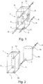
- the Fig. 1 shows a schematic view of a heat exchanger 1.
- the heat exchanger 1 is divided into a cooling section 6 and in an inner heat exchanger 5.
- a refrigerant in a high-pressure phase (high-pressure refrigerant) 2 is brought into thermal contact with a coolant 3, so that a heat transfer from the high-pressure refrigerant 2 to the coolant 3 is formed.
- the Hochdrucckältesch 2 is thus further cooled.
- the high-pressure refrigerant 2 flows via a fluid inlet 7 into the cooling section 6.
- a plurality of flow channels are arranged, which are partially flowed through by the high-pressure refrigerant 2 and through which the coolant 3 flows.
- Within the internal heat exchanger 5 also a plurality of flow channels are arranged, wherein a number of these flow channels is associated with the low-pressure refrigerant 4 and a further number of channels is associated with the high-pressure refrigerant 2. Both the flow channels in the internal heat exchanger 5 and in the cooling section 6 are not shown for reasons of clarity.
- the flow channels for the high-pressure refrigerant 2, the coolant 3 and the low-pressure refrigerant 4 may be arranged within the heat exchanger in any order.
- the flow channels of the different fluids can be arranged, for example, alternately.
- an arrangement may be provided in which a plurality of flow channels for the same fluid are arranged adjacent to each other.
- the flow of the high-pressure refrigerant 2 through the heat exchanger 1 runs along the fluid inlet 7 through the flow channels in the interior of the cooling section 6 along the flow channels in the inner heat exchanger 5 and finally out of the heat exchanger 1 from the fluid outlet 8.
- the coolant 3 flows via the fluid inlet 9 into the cooling section 6 of the heat exchanger 1 and there along the flow channels within the cooling section 6 to the fluid outlet 10. There, it flows out of the heat exchanger 1 from.
- the low-pressure refrigerant 4 flows via a fluid inlet 11 into the inner heat exchanger 5 and there along the flow channels associated therewith through the inner heat exchanger 5. It finally flows out of the inner heat exchanger 5 via the fluid outlet 12.
- deflections may be provided, whereby the flow direction of the individual fluids is deflected. In this case, areas can be generated in which two fluids flow in cocurrent or in countercurrent to each other.
- the high-pressure refrigerant 2 is within the refrigerant circuit, softer in the Fig. 1 is not shown, transferred via a likewise not shown expansion valve in a low pressure phase and thus to the low pressure refrigerant 4.
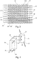
- the Fig. 2 shows a further schematic view of the heat exchanger 1, as already in Fig. 1 was shown.
- the with the Fig. 1 identical features of the heat exchanger 1 are denoted by identical reference numerals.
- an accumulator 13 is shown.
- This accumulator 13 serves to store the low-pressure refrigerant 4, which flows into the accumulator 13 via a fluid inlet 14 and flows out of the accumulator 13 via a fluid outlet 15.
- the accumulator 13 may include means for filtering, cleaning and drying the low-pressure refrigerant 4. Via a storage volume in the interior of the accumulator 13, a fluctuation of the refrigerant volume within the refrigerant circuit can be compensated. This ensures a stable cooling of the refrigerant 2, 4 within the refrigerant circuit. Likewise, leaks within the refrigerant circuit can be at least partially compensated.
- the accumulator 13 is arranged immediately in front of the fluid inlet 11 of the heat exchanger 1.
- the low-pressure refrigerant 4 thus flows directly from the accumulator 13 into the internal heat exchanger 5 of the heat exchanger 1.
- the accumulator 13 can as in Fig. 2 be shown as a separate component, which is arranged in the vicinity of the heat exchanger 1.
- an integration of the accumulator in the heat exchanger is providable.
- the design of the heat exchanger and the accumulator in a unit is particularly advantageous in terms of the required installation space of the unit.
- the Fig. 3 shows a sectional view through a heat exchanger.
- the arrangement of the various flow channels 23, 24, 25 is shown.
- the high-pressure refrigerant 20 is assigned the first flow channel 23, which divides into a first region 23a and a second region 23b.
- the high-pressure refrigerant 20 comes into thermal contact with a coolant 21, whereby a heat transfer between the high-pressure refrigerant 20 and the coolant 21 is formed.
- the second region 23b of the first flow channel 23 the heat transfer between the high-pressure refrigerant 20 and the low-pressure refrigerant 22 takes place.
- the flow channel 23 is in thermal contact with another flow channel 24.
- the flow channel 24 in this case has a plurality of rib elements 26, which serve to increase the heat transfer surface.
- FIG. 3 shown example of the arrangement of the flow channels within a heat exchanger provides that the heat transfer between the high-pressure refrigerant 20 and the coolant 21 via flow channels in pipe rib design.
- the first region 23a of the flow channels 23 flows through the refrigerant, wherein the flow channels 24 are arranged between the flow channels 23 and by a coolant, such as the ambient air or cooling water, flows through.
- a coolant such as the ambient air or cooling water
- the first regions 23a of the flow channels 23 are substantially bypassed by the coolant 21 while flowing through the high-pressure refrigerant 20.
- the operation of the cooling section 27 corresponds to the ordinary pipe-fin type heat exchanger in which a fluid flows through a first number of pipes while a second fluid flows around this number of pipes.
- Fig. 3 shown arrangement can be covered by a housing.
- the housing can be flowed through by the coolant whereby the tubes through which the refrigerant flows, are flowed around.
- the heat transfer between the high-pressure refrigerant 20 and the low-pressure refrigerant 22 takes place between the second region 23b of the flow channels 23 of the high-pressure refrigerant 20 and the flow channels 25 of the low-pressure refrigerant 22.
- the area of Fig. 3 which is formed by the flow channels 24 and the first region 23 of the first flow channels 23, corresponds to the Abkühlumble 27.
- the range of Fig. 3 which is formed by the second region 23b of the first flow channels 23 and the flow channels 25, corresponds to the internal heat exchanger 28.
- the cooling section 27 can be represented by flow channels brought together in thermally conductive contact. It is also conceivable to use a liquid coolant.
- the first unit of the heat exchanger which is formed by the second region 23b of the first flow channel 23 and the second flow channel 25 and the second unit of the heat exchanger, which is formed from the first region 23a of the first flow channel 23 and the third flow channel 24 can optionally by a construction in stacking disk construction, in pipe-fin construction or by a juxtaposition of pipes, which are flowed through by the refrigerant or the coolant to be formed.
- a housing is advantageously provided, which surrounds the arrangement of tubes and turbulence inserts.
- the Fig. 4 shows an alternative embodiment of the heat exchanger 30.
- the heat exchanger 30 now consists only of a cooling section, in which the high-pressure refrigerant 39 is brought into thermal contact with the coolant 40.
- the structure of the heat exchanger 30 corresponds essentially to the cooling section 6 of the heat exchanger 1 of Fig. 1 ,
- a low-pressure refrigerant 41 flows in via the fluid inlet 32 and out of the accumulator 31 out of the fluid outlet 33.
- the high-pressure refrigerant 39 which has flowed out of the fluid outlet 36 of the heat exchanger 30, flows into the accumulator 31.
- the accumulator 31 has in particular the second region 34 of the first flow channel, which is brought into thermally conductive contact with the low-pressure refrigerant 41.
- the accumulator 31 may have in its interior a plurality of flow channels.
- the accumulator 31 of the Fig. 4 be designed as a separate component as shown. In alternative embodiments, it may also be integrated directly into the heat exchanger 30.
- the positioning of the fluid inlets and the fluid outlets represents only one possibility of the arrangement.
- the fluid inlets and fluid outlets can be arbitrarily arranged on the heat exchanger and the accumulator.
- Advantageous solutions result in particular by the choice of the internal structure of the Heat exchanger.
- the fluid inlets and the fluid outlets are advantageously arranged on the two outer disc elements closing off the stack.
- Fig. 1 to 4 the refrigerant circuit surrounding each heat exchanger is not shown.
- the embodiments of the Fig. 1 to 4 are merely exemplary in nature and are not an exhaustive list and representation of the embodiments. They are not of a restrictive nature.
Landscapes
- Engineering & Computer Science (AREA)
- Physics & Mathematics (AREA)
- Thermal Sciences (AREA)
- Mechanical Engineering (AREA)
- General Engineering & Computer Science (AREA)
- Heat-Exchange Devices With Radiators And Conduit Assemblies (AREA)
Claims (10)
- Echangeur de chaleur (1, 30) comprenant un premier conduit d'écoulement (23) pour un fluide frigorigène (2, 20, 39), comprenant un deuxième conduit d'écoulement (25) pour un fluide frigorigène (4, 22, 41) et comprenant un troisième conduit d'écoulement (24) pour un liquide de refroidissement (3, 21, 40), où le premier conduit d'écoulement (23) présente une première zone (23a) servant au premier refroidissement du fluide frigorigène (2, 20, 39), et présente une deuxième zone (23b) servant au refroidissement supplémentaire du fluide frigorigène (2, 20, 39), où le fluide frigorigène (2, 20, 39) peut s'écouler, dans le premier conduit d'écoulement (23), pendant une phase de haute pression, et le fluide frigorigène (4, 22, 41) peut s'écouler, dans le deuxième conduit d'écoulement (25), pendant une phase de basse pression, où un premier transfert de chaleur a lieu entre le fluide frigorigène se trouvant dans la première zone (23a) du premier conduit d'écoulement (23), et le liquide de refroidissement en circulation dans le troisième conduit d'écoulement (24), et un deuxième transfert de chaleur a lieu entre le fluide frigorigène se trouvant dans la deuxième zone (23b) du premier conduit d'écoulement (23), et le fluide frigorigène en circulation dans le deuxième conduit d'écoulement (25), où l'échangeur de chaleur (1, 30) présente un accumulateur (13, 31) qui présente un volume d'accumulateur servant au stockage du fluide frigorigène (4, 22, 41) et / ou des moyens servant à la filtration et / ou des moyens servant à la dessiccation du fluide frigorigène (4, 22, 41), où le débordement de fluide frigorigène sortant de la deuxième zone (23b) du premier conduit d'écoulement (23) et passant dans le deuxième conduit d'écoulement (25) se produit via l'accumulateur (13, 31), et caractérisé en ce que l'accumulateur (31) présente la deuxième zone (23b, 34) du premier conduit d'écoulement (23) et le deuxième conduit d'écoulement (25), où un transfert de chaleur a lieu, à l'intérieur de l'accumulateur (31), entre la deuxième zone (23b, 34) du premier conduit d'écoulement (23), et le deuxième conduit d'écoulement (25).
- Echangeur de chaleur (1, 30) selon la revendication 1, caractérisé en ce que la deuxième zone (23b) du premier conduit d'écoulement (23) et le deuxième conduit d'écoulement (25) forment un premier ensemble, et la première zone (23a) du premier conduit d'écoulement (23) et le troisième conduit d'écoulement (24) forment un deuxième ensemble, où le premier ensemble et le deuxième ensemble peuvent être assemblés pour former un ensemble unitaire.
- Echangeur de chaleur (1, 30) selon la revendication 1 ou 2, caractérisé en ce que le troisième conduit d'écoulement (24) est contigu à la première zone (23a) du premier conduit d'écoulement (23), et le deuxième conduit d'écoulement (25) est contigu à la deuxième zone (23b) du premier conduit d'écoulement (23).
- Echangeur de chaleur (1, 30) selon l'une quelconque des revendications 1 à 3, caractérisé en ce que le premier ensemble et / ou le deuxième ensemble est formé en étant du type à plaques empilées.
- Echangeur de chaleur (1, 30) selon l'une quelconque des revendications 1 à 4, caractérisé en ce que le premier ensemble et / ou le deuxième ensemble est formé en étant du type à tubes et à ailettes.
- Echangeur de chaleur (1, 30) selon l'une quelconque des revendications 1 à 5, caractérisé en ce que le premier ensemble et / ou le deuxième ensemble est formé par une pluralité de tubes, où les tubes sont disposés en étant contigus les uns aux autres et sont au moins en partie en contact thermique les uns avec les autres, où les tubes peuvent être traversés à chaque fois par le fluide frigorigène (2, 4, 20, 22, 39, 41) et / ou par le liquide de refroidissement (3, 21, 40).
- Echangeur de chaleur (1, 30) selon l'une quelconque des revendications 1 à 6, caractérisé en ce que le premier ensemble et / ou le deuxième ensemble est formé par une pluralité de tubes, où des pièces intercalaires (26) générant des turbulences sont disposées entre les tubes, où l'agencement de tubes et de pièces intercalaires (26) générant des turbulences est enveloppé par un carter, où les tubes peuvent être traversés par un liquide de refroidissement (3, 21, 40) et / ou par un fluide frigorigène (2, 4, 20, 22, 39, 41) et peuvent être baignés par un liquide de refroidissement (3, 21, 40) et / ou par un fluide frigorigène (2, 4, 20, 22, 39, 41).
- Echangeur de chaleur (1, 30) selon l'une quelconque des revendications précédentes, caractérisé en ce qu'un ou plusieurs des conduits d'écoulement (23, 24, 25) subissent, dans leur direction d'écoulement, un ou plusieurs retours de flux, faisant que les écoulements de fluide, dans les conduits d'écoulement (23, 24, 25), peuvent se produire, les uns par rapport aux autres, suivant un flux de même sens et / ou suivant un flux de sens opposé et / ou suivant des flux croisés.
- Echangeur de chaleur (1, 30) selon l'une quelconque des revendications précédentes, caractérisé en ce que l'accumulateur (13, 31) et l'échangeur de chaleur (1, 30) sont conçus comme un ensemble unitaire.
- Utilisation de l'échangeur de chaleur selon l'une quelconque des revendications précédentes, où l'on utilise, comme fluide frigorigène, du CO2 (R744).
Applications Claiming Priority (2)
| Application Number | Priority Date | Filing Date | Title |
|---|---|---|---|
| DE102012221925.0A DE102012221925A1 (de) | 2012-11-29 | 2012-11-29 | Wärmeübertrager |
| PCT/EP2013/074865 WO2014083061A1 (fr) | 2012-11-29 | 2013-11-27 | Échangeur thermique |
Publications (2)
| Publication Number | Publication Date |
|---|---|
| EP2926073A1 EP2926073A1 (fr) | 2015-10-07 |
| EP2926073B1 true EP2926073B1 (fr) | 2019-07-10 |
Family
ID=49709651
Family Applications (1)
| Application Number | Title | Priority Date | Filing Date |
|---|---|---|---|
| EP13799266.5A Active EP2926073B1 (fr) | 2012-11-29 | 2013-11-27 | Échangeur thermique |
Country Status (5)
| Country | Link |
|---|---|
| US (1) | US9945614B2 (fr) |
| EP (1) | EP2926073B1 (fr) |
| CN (1) | CN104823014B (fr) |
| DE (1) | DE102012221925A1 (fr) |
| WO (1) | WO2014083061A1 (fr) |
Families Citing this family (6)
| Publication number | Priority date | Publication date | Assignee | Title |
|---|---|---|---|---|
| DE102014221168A1 (de) | 2014-10-17 | 2016-04-21 | Mahle International Gmbh | Wärmeübertrager |
| CN111615290B (zh) * | 2019-02-25 | 2022-07-26 | 龙大昌精密工业有限公司 | 冷凝器的散热结构 |
| DE102020202313A1 (de) | 2020-02-24 | 2021-08-26 | Mahle International Gmbh | Wärmeübertrager |
| EP4088565A1 (fr) * | 2021-05-12 | 2022-11-16 | L'Air Liquide, société anonyme pour l'Étude et l'Exploitation des procédés Georges Claude | Procédé de contrôle de l'atmosphère interne à une serre en terme d'humidité et de température |
| DE102021213376A1 (de) | 2021-11-26 | 2023-06-01 | Mahle International Gmbh | Wärmeübertrager und Kältemittelkreislauf mit einem Wärmeübertrager |
| DE102022201431A1 (de) * | 2022-02-11 | 2023-08-17 | Mahle International Gmbh | Sammler für einen Kältemittelkreislauf |
Family Cites Families (15)
| Publication number | Priority date | Publication date | Assignee | Title |
|---|---|---|---|---|
| DE491409C (fr) * | ||||
| JPH1019421A (ja) * | 1996-07-05 | 1998-01-23 | Nippon Soken Inc | 冷凍サイクルおよびこのサイクルに用いるアキュムレータ |
| US6892803B2 (en) * | 2002-11-19 | 2005-05-17 | Modine Manufacturing Company | High pressure heat exchanger |
| DE10328746A1 (de) * | 2003-06-25 | 2005-01-13 | Behr Gmbh & Co. Kg | Vorrichtung zum mehrstufigen Wärmeaustausch und Verfahren zur Herstellung einer derartigen Vorrichtung |
| US7343965B2 (en) * | 2004-01-20 | 2008-03-18 | Modine Manufacturing Company | Brazed plate high pressure heat exchanger |
| CN100582627C (zh) * | 2005-05-24 | 2010-01-20 | 达纳加拿大公司 | 多流体热交换器 |
| US7753105B2 (en) * | 2006-05-16 | 2010-07-13 | Delphi Technologies, Inc. | Liquid cooled condenser having an integrated heat exchanger |
| US8191615B2 (en) * | 2006-11-24 | 2012-06-05 | Dana Canada Corporation | Linked heat exchangers having three fluids |
| FR2924490A1 (fr) * | 2007-11-29 | 2009-06-05 | Valeo Systemes Thermiques | Condenseur pour circuit de climatisation avec partie de sous-refroidissement |
| FR2940420B1 (fr) | 2008-12-22 | 2010-12-31 | Valeo Systemes Thermiques | Dispositif combine comprenant un echangeur de chaleur interne et un accumulateur constitutifs d'une bouche de climatisation |
| US8011201B2 (en) * | 2009-09-30 | 2011-09-06 | Thermo Fisher Scientific (Asheville) Llc | Refrigeration system mounted within a deck |
| US8590328B2 (en) * | 2010-02-03 | 2013-11-26 | Hill Phoenix, Inc. | Refrigeration system with multi-function heat exchanger |
| DE102010048015B4 (de) * | 2010-10-09 | 2015-11-05 | Modine Manufacturing Co. | Anlage mit einem Wärmeübertrager |
| US20120080173A1 (en) * | 2010-10-04 | 2012-04-05 | Ford Global Technologies, Llc | Heat exchanger assembly having multiple heat exchangers |
| DE102011007701A1 (de) * | 2011-04-19 | 2012-10-25 | Behr Gmbh & Co. Kg | Kältemittelkondensatorbaugruppe |
-
2012
- 2012-11-29 DE DE102012221925.0A patent/DE102012221925A1/de not_active Withdrawn
-
2013
- 2013-11-27 CN CN201380061683.5A patent/CN104823014B/zh not_active Expired - Fee Related
- 2013-11-27 WO PCT/EP2013/074865 patent/WO2014083061A1/fr not_active Ceased
- 2013-11-27 EP EP13799266.5A patent/EP2926073B1/fr active Active
-
2015
- 2015-05-29 US US14/725,372 patent/US9945614B2/en not_active Expired - Fee Related
Non-Patent Citations (1)
| Title |
|---|
| None * |
Also Published As
| Publication number | Publication date |
|---|---|
| CN104823014B (zh) | 2017-06-23 |
| DE102012221925A1 (de) | 2014-06-05 |
| WO2014083061A1 (fr) | 2014-06-05 |
| US9945614B2 (en) | 2018-04-17 |
| CN104823014A (zh) | 2015-08-05 |
| US20150260457A1 (en) | 2015-09-17 |
| EP2926073A1 (fr) | 2015-10-07 |
Similar Documents
| Publication | Publication Date | Title |
|---|---|---|
| EP3119623B1 (fr) | Module de chauffage et de refroidissement | |
| EP2904335B1 (fr) | Condenseur | |
| DE69219421T2 (de) | Wärmetauscher | |
| EP0789213B1 (fr) | Echangeur de chaleur pour véhicule automobile | |
| WO2014083061A1 (fr) | Échangeur thermique | |
| DE102010048015A1 (de) | Anlage mit einem Wärmeübertrager | |
| DE102013217287A1 (de) | Innerer Wärmeübertrager für einen Kältemittelkreislauf, insbesondere für eine Klimaanlage eines Kraftfahrzeuges, und einen Kältemittelkreislauf mit einem Verdampfer | |
| DE102018110370A1 (de) | Wärmetauscher für Fahrzeug | |
| DE102013209157A1 (de) | Kondensator | |
| DE60307323T2 (de) | Wärmetauscher | |
| DE102012209431A1 (de) | Effizienter innerer Wärmeübertrager | |
| DE102014113863A1 (de) | Vorrichtung zur Wärmeübertragung und Verfahren zur Herstellung der Vorrichtung | |
| EP3009780A1 (fr) | Fluide caloporteur | |
| DE202014101213U1 (de) | Heizkühlmodul | |
| DE102019132955B4 (de) | Wärmeübertrager mit integriertem Trockner und Platte für einen Plattenwärmeübertrager | |
| EP2937658B1 (fr) | Fluide caloporteur interne | |
| WO2014095594A1 (fr) | Échangeur de chaleur | |
| DE102011007784A1 (de) | Kondensator | |
| DE102011089091A1 (de) | Wärmeübertrager | |
| EP2570754A2 (fr) | Système d'évaporateur multi-canal | |
| EP2818817B1 (fr) | Composant de condensateur | |
| DE102005028510A1 (de) | Verstellbarer innerer Wärmeübertrager | |
| EP3569953A1 (fr) | Dispositif de circuit réfrigérant et procédé de fonctionnement d'un dispositif de circuit réfrigérant doté d'un évaporateur hybride | |
| WO2004005826A1 (fr) | Echangeur de chaleur | |
| DE102011005177A1 (de) | Kondensator |
Legal Events
| Date | Code | Title | Description |
|---|---|---|---|
| PUAI | Public reference made under article 153(3) epc to a published international application that has entered the european phase |
Free format text: ORIGINAL CODE: 0009012 |
|
| 17P | Request for examination filed |
Effective date: 20150629 |
|
| AK | Designated contracting states |
Kind code of ref document: A1 Designated state(s): AL AT BE BG CH CY CZ DE DK EE ES FI FR GB GR HR HU IE IS IT LI LT LU LV MC MK MT NL NO PL PT RO RS SE SI SK SM TR |
|
| AX | Request for extension of the european patent |
Extension state: BA ME |
|
| DAX | Request for extension of the european patent (deleted) | ||
| RAP1 | Party data changed (applicant data changed or rights of an application transferred) |
Owner name: MAHLE INTERNATIONAL GMBH |
|
| STAA | Information on the status of an ep patent application or granted ep patent |
Free format text: STATUS: EXAMINATION IS IN PROGRESS |
|
| 17Q | First examination report despatched |
Effective date: 20180615 |
|
| GRAP | Despatch of communication of intention to grant a patent |
Free format text: ORIGINAL CODE: EPIDOSNIGR1 |
|
| STAA | Information on the status of an ep patent application or granted ep patent |
Free format text: STATUS: GRANT OF PATENT IS INTENDED |
|
| INTG | Intention to grant announced |
Effective date: 20190225 |
|
| GRAS | Grant fee paid |
Free format text: ORIGINAL CODE: EPIDOSNIGR3 |
|
| GRAA | (expected) grant |
Free format text: ORIGINAL CODE: 0009210 |
|
| STAA | Information on the status of an ep patent application or granted ep patent |
Free format text: STATUS: THE PATENT HAS BEEN GRANTED |
|
| AK | Designated contracting states |
Kind code of ref document: B1 Designated state(s): AL AT BE BG CH CY CZ DE DK EE ES FI FR GB GR HR HU IE IS IT LI LT LU LV MC MK MT NL NO PL PT RO RS SE SI SK SM TR |
|
| REG | Reference to a national code |
Ref country code: GB Ref legal event code: FG4D Free format text: NOT ENGLISH |
|
| REG | Reference to a national code |
Ref country code: CH Ref legal event code: EP Ref country code: AT Ref legal event code: REF Ref document number: 1154037 Country of ref document: AT Kind code of ref document: T Effective date: 20190715 |
|
| REG | Reference to a national code |
Ref country code: DE Ref legal event code: R096 Ref document number: 502013013155 Country of ref document: DE |
|
| REG | Reference to a national code |
Ref country code: IE Ref legal event code: FG4D Free format text: LANGUAGE OF EP DOCUMENT: GERMAN |
|
| REG | Reference to a national code |
Ref country code: NL Ref legal event code: MP Effective date: 20190710 |
|
| REG | Reference to a national code |
Ref country code: LT Ref legal event code: MG4D |
|
| PG25 | Lapsed in a contracting state [announced via postgrant information from national office to epo] |
Ref country code: NO Free format text: LAPSE BECAUSE OF FAILURE TO SUBMIT A TRANSLATION OF THE DESCRIPTION OR TO PAY THE FEE WITHIN THE PRESCRIBED TIME-LIMIT Effective date: 20191010 Ref country code: BG Free format text: LAPSE BECAUSE OF FAILURE TO SUBMIT A TRANSLATION OF THE DESCRIPTION OR TO PAY THE FEE WITHIN THE PRESCRIBED TIME-LIMIT Effective date: 20191010 Ref country code: SE Free format text: LAPSE BECAUSE OF FAILURE TO SUBMIT A TRANSLATION OF THE DESCRIPTION OR TO PAY THE FEE WITHIN THE PRESCRIBED TIME-LIMIT Effective date: 20190710 Ref country code: HR Free format text: LAPSE BECAUSE OF FAILURE TO SUBMIT A TRANSLATION OF THE DESCRIPTION OR TO PAY THE FEE WITHIN THE PRESCRIBED TIME-LIMIT Effective date: 20190710 Ref country code: LT Free format text: LAPSE BECAUSE OF FAILURE TO SUBMIT A TRANSLATION OF THE DESCRIPTION OR TO PAY THE FEE WITHIN THE PRESCRIBED TIME-LIMIT Effective date: 20190710 Ref country code: NL Free format text: LAPSE BECAUSE OF FAILURE TO SUBMIT A TRANSLATION OF THE DESCRIPTION OR TO PAY THE FEE WITHIN THE PRESCRIBED TIME-LIMIT Effective date: 20190710 Ref country code: PT Free format text: LAPSE BECAUSE OF FAILURE TO SUBMIT A TRANSLATION OF THE DESCRIPTION OR TO PAY THE FEE WITHIN THE PRESCRIBED TIME-LIMIT Effective date: 20191111 Ref country code: FI Free format text: LAPSE BECAUSE OF FAILURE TO SUBMIT A TRANSLATION OF THE DESCRIPTION OR TO PAY THE FEE WITHIN THE PRESCRIBED TIME-LIMIT Effective date: 20190710 |
|
| PG25 | Lapsed in a contracting state [announced via postgrant information from national office to epo] |
Ref country code: GR Free format text: LAPSE BECAUSE OF FAILURE TO SUBMIT A TRANSLATION OF THE DESCRIPTION OR TO PAY THE FEE WITHIN THE PRESCRIBED TIME-LIMIT Effective date: 20191011 Ref country code: ES Free format text: LAPSE BECAUSE OF FAILURE TO SUBMIT A TRANSLATION OF THE DESCRIPTION OR TO PAY THE FEE WITHIN THE PRESCRIBED TIME-LIMIT Effective date: 20190710 Ref country code: RS Free format text: LAPSE BECAUSE OF FAILURE TO SUBMIT A TRANSLATION OF THE DESCRIPTION OR TO PAY THE FEE WITHIN THE PRESCRIBED TIME-LIMIT Effective date: 20190710 Ref country code: IS Free format text: LAPSE BECAUSE OF FAILURE TO SUBMIT A TRANSLATION OF THE DESCRIPTION OR TO PAY THE FEE WITHIN THE PRESCRIBED TIME-LIMIT Effective date: 20191110 Ref country code: AL Free format text: LAPSE BECAUSE OF FAILURE TO SUBMIT A TRANSLATION OF THE DESCRIPTION OR TO PAY THE FEE WITHIN THE PRESCRIBED TIME-LIMIT Effective date: 20190710 Ref country code: LV Free format text: LAPSE BECAUSE OF FAILURE TO SUBMIT A TRANSLATION OF THE DESCRIPTION OR TO PAY THE FEE WITHIN THE PRESCRIBED TIME-LIMIT Effective date: 20190710 |
|
| PG25 | Lapsed in a contracting state [announced via postgrant information from national office to epo] |
Ref country code: TR Free format text: LAPSE BECAUSE OF FAILURE TO SUBMIT A TRANSLATION OF THE DESCRIPTION OR TO PAY THE FEE WITHIN THE PRESCRIBED TIME-LIMIT Effective date: 20190710 |
|
| PG25 | Lapsed in a contracting state [announced via postgrant information from national office to epo] |
Ref country code: DK Free format text: LAPSE BECAUSE OF FAILURE TO SUBMIT A TRANSLATION OF THE DESCRIPTION OR TO PAY THE FEE WITHIN THE PRESCRIBED TIME-LIMIT Effective date: 20190710 Ref country code: EE Free format text: LAPSE BECAUSE OF FAILURE TO SUBMIT A TRANSLATION OF THE DESCRIPTION OR TO PAY THE FEE WITHIN THE PRESCRIBED TIME-LIMIT Effective date: 20190710 Ref country code: IT Free format text: LAPSE BECAUSE OF FAILURE TO SUBMIT A TRANSLATION OF THE DESCRIPTION OR TO PAY THE FEE WITHIN THE PRESCRIBED TIME-LIMIT Effective date: 20190710 Ref country code: RO Free format text: LAPSE BECAUSE OF FAILURE TO SUBMIT A TRANSLATION OF THE DESCRIPTION OR TO PAY THE FEE WITHIN THE PRESCRIBED TIME-LIMIT Effective date: 20190710 Ref country code: PL Free format text: LAPSE BECAUSE OF FAILURE TO SUBMIT A TRANSLATION OF THE DESCRIPTION OR TO PAY THE FEE WITHIN THE PRESCRIBED TIME-LIMIT Effective date: 20190710 |
|
| PG25 | Lapsed in a contracting state [announced via postgrant information from national office to epo] |
Ref country code: IS Free format text: LAPSE BECAUSE OF FAILURE TO SUBMIT A TRANSLATION OF THE DESCRIPTION OR TO PAY THE FEE WITHIN THE PRESCRIBED TIME-LIMIT Effective date: 20200224 Ref country code: SK Free format text: LAPSE BECAUSE OF FAILURE TO SUBMIT A TRANSLATION OF THE DESCRIPTION OR TO PAY THE FEE WITHIN THE PRESCRIBED TIME-LIMIT Effective date: 20190710 Ref country code: CZ Free format text: LAPSE BECAUSE OF FAILURE TO SUBMIT A TRANSLATION OF THE DESCRIPTION OR TO PAY THE FEE WITHIN THE PRESCRIBED TIME-LIMIT Effective date: 20190710 Ref country code: SM Free format text: LAPSE BECAUSE OF FAILURE TO SUBMIT A TRANSLATION OF THE DESCRIPTION OR TO PAY THE FEE WITHIN THE PRESCRIBED TIME-LIMIT Effective date: 20190710 |
|
| REG | Reference to a national code |
Ref country code: DE Ref legal event code: R097 Ref document number: 502013013155 Country of ref document: DE |
|
| REG | Reference to a national code |
Ref country code: CH Ref legal event code: PL |
|
| PLBE | No opposition filed within time limit |
Free format text: ORIGINAL CODE: 0009261 |
|
| STAA | Information on the status of an ep patent application or granted ep patent |
Free format text: STATUS: NO OPPOSITION FILED WITHIN TIME LIMIT |
|
| PG2D | Information on lapse in contracting state deleted |
Ref country code: IS |
|
| PG25 | Lapsed in a contracting state [announced via postgrant information from national office to epo] |
Ref country code: CH Free format text: LAPSE BECAUSE OF NON-PAYMENT OF DUE FEES Effective date: 20191130 Ref country code: LI Free format text: LAPSE BECAUSE OF NON-PAYMENT OF DUE FEES Effective date: 20191130 Ref country code: LU Free format text: LAPSE BECAUSE OF NON-PAYMENT OF DUE FEES Effective date: 20191127 Ref country code: MC Free format text: LAPSE BECAUSE OF FAILURE TO SUBMIT A TRANSLATION OF THE DESCRIPTION OR TO PAY THE FEE WITHIN THE PRESCRIBED TIME-LIMIT Effective date: 20190710 |
|
| 26N | No opposition filed |
Effective date: 20200603 |
|
| REG | Reference to a national code |
Ref country code: BE Ref legal event code: MM Effective date: 20191130 |
|
| PG25 | Lapsed in a contracting state [announced via postgrant information from national office to epo] |
Ref country code: SI Free format text: LAPSE BECAUSE OF FAILURE TO SUBMIT A TRANSLATION OF THE DESCRIPTION OR TO PAY THE FEE WITHIN THE PRESCRIBED TIME-LIMIT Effective date: 20190710 |
|
| GBPC | Gb: european patent ceased through non-payment of renewal fee |
Effective date: 20191127 |
|
| PG25 | Lapsed in a contracting state [announced via postgrant information from national office to epo] |
Ref country code: FR Free format text: LAPSE BECAUSE OF NON-PAYMENT OF DUE FEES Effective date: 20191130 Ref country code: GB Free format text: LAPSE BECAUSE OF NON-PAYMENT OF DUE FEES Effective date: 20191127 Ref country code: IE Free format text: LAPSE BECAUSE OF NON-PAYMENT OF DUE FEES Effective date: 20191127 |
|
| PG25 | Lapsed in a contracting state [announced via postgrant information from national office to epo] |
Ref country code: BE Free format text: LAPSE BECAUSE OF NON-PAYMENT OF DUE FEES Effective date: 20191130 |
|
| REG | Reference to a national code |
Ref country code: AT Ref legal event code: MM01 Ref document number: 1154037 Country of ref document: AT Kind code of ref document: T Effective date: 20191127 |
|
| PG25 | Lapsed in a contracting state [announced via postgrant information from national office to epo] |
Ref country code: AT Free format text: LAPSE BECAUSE OF NON-PAYMENT OF DUE FEES Effective date: 20191127 |
|
| PG25 | Lapsed in a contracting state [announced via postgrant information from national office to epo] |
Ref country code: CY Free format text: LAPSE BECAUSE OF FAILURE TO SUBMIT A TRANSLATION OF THE DESCRIPTION OR TO PAY THE FEE WITHIN THE PRESCRIBED TIME-LIMIT Effective date: 20190710 |
|
| PG25 | Lapsed in a contracting state [announced via postgrant information from national office to epo] |
Ref country code: MT Free format text: LAPSE BECAUSE OF FAILURE TO SUBMIT A TRANSLATION OF THE DESCRIPTION OR TO PAY THE FEE WITHIN THE PRESCRIBED TIME-LIMIT Effective date: 20190710 Ref country code: HU Free format text: LAPSE BECAUSE OF FAILURE TO SUBMIT A TRANSLATION OF THE DESCRIPTION OR TO PAY THE FEE WITHIN THE PRESCRIBED TIME-LIMIT; INVALID AB INITIO Effective date: 20131127 |
|
| PG25 | Lapsed in a contracting state [announced via postgrant information from national office to epo] |
Ref country code: MK Free format text: LAPSE BECAUSE OF FAILURE TO SUBMIT A TRANSLATION OF THE DESCRIPTION OR TO PAY THE FEE WITHIN THE PRESCRIBED TIME-LIMIT Effective date: 20190710 |
|
| P01 | Opt-out of the competence of the unified patent court (upc) registered |
Effective date: 20240527 |
|
| PGFP | Annual fee paid to national office [announced via postgrant information from national office to epo] |
Ref country code: DE Payment date: 20241121 Year of fee payment: 12 |