EP2926207B1 - Rohrleitungssystem für flüssigkeiten - Google Patents
Rohrleitungssystem für flüssigkeiten Download PDFInfo
- Publication number
- EP2926207B1 EP2926207B1 EP13858462.8A EP13858462A EP2926207B1 EP 2926207 B1 EP2926207 B1 EP 2926207B1 EP 13858462 A EP13858462 A EP 13858462A EP 2926207 B1 EP2926207 B1 EP 2926207B1
- Authority
- EP
- European Patent Office
- Prior art keywords
- pipeline
- water
- irrigation
- pump
- gate
- Prior art date
- Legal status (The legal status is an assumption and is not a legal conclusion. Google has not performed a legal analysis and makes no representation as to the accuracy of the status listed.)
- Active
Links
Images


Classifications
-
- F—MECHANICAL ENGINEERING; LIGHTING; HEATING; WEAPONS; BLASTING
- F04—POSITIVE - DISPLACEMENT MACHINES FOR LIQUIDS; PUMPS FOR LIQUIDS OR ELASTIC FLUIDS
- F04D—NON-POSITIVE-DISPLACEMENT PUMPS
- F04D15/00—Control, e.g. regulation, of pumps, pumping installations or systems
- F04D15/0005—Control, e.g. regulation, of pumps, pumping installations or systems by using valves
-
- G—PHYSICS
- G01—MEASURING; TESTING
- G01M—TESTING STATIC OR DYNAMIC BALANCE OF MACHINES OR STRUCTURES; TESTING OF STRUCTURES OR APPARATUS, NOT OTHERWISE PROVIDED FOR
- G01M3/00—Investigating fluid-tightness of structures
- G01M3/02—Investigating fluid-tightness of structures by using fluid or vacuum
- G01M3/26—Investigating fluid-tightness of structures by using fluid or vacuum by measuring rate of loss or gain of fluid, e.g. by pressure-responsive devices, by flow detectors
- G01M3/28—Investigating fluid-tightness of structures by using fluid or vacuum by measuring rate of loss or gain of fluid, e.g. by pressure-responsive devices, by flow detectors for pipes, cables or tubes; for pipe joints or seals; for valves ; for welds
- G01M3/2807—Investigating fluid-tightness of structures by using fluid or vacuum by measuring rate of loss or gain of fluid, e.g. by pressure-responsive devices, by flow detectors for pipes, cables or tubes; for pipe joints or seals; for valves ; for welds for pipes
-
- F—MECHANICAL ENGINEERING; LIGHTING; HEATING; WEAPONS; BLASTING
- F17—STORING OR DISTRIBUTING GASES OR LIQUIDS
- F17D—PIPE-LINE SYSTEMS; PIPE-LINES
- F17D5/00—Protection or supervision of installations
- F17D5/02—Preventing, monitoring, or locating loss
-
- F—MECHANICAL ENGINEERING; LIGHTING; HEATING; WEAPONS; BLASTING
- F04—POSITIVE - DISPLACEMENT MACHINES FOR LIQUIDS; PUMPS FOR LIQUIDS OR ELASTIC FLUIDS
- F04D—NON-POSITIVE-DISPLACEMENT PUMPS
- F04D15/00—Control, e.g. regulation, of pumps, pumping installations or systems
- F04D15/0027—Varying behaviour or the very pump
-
- F—MECHANICAL ENGINEERING; LIGHTING; HEATING; WEAPONS; BLASTING
- F04—POSITIVE - DISPLACEMENT MACHINES FOR LIQUIDS; PUMPS FOR LIQUIDS OR ELASTIC FLUIDS
- F04D—NON-POSITIVE-DISPLACEMENT PUMPS
- F04D15/00—Control, e.g. regulation, of pumps, pumping installations or systems
- F04D15/0066—Control, e.g. regulation, of pumps, pumping installations or systems by changing the speed, e.g. of the driving engine
-
- F—MECHANICAL ENGINEERING; LIGHTING; HEATING; WEAPONS; BLASTING
- F04—POSITIVE - DISPLACEMENT MACHINES FOR LIQUIDS; PUMPS FOR LIQUIDS OR ELASTIC FLUIDS
- F04D—NON-POSITIVE-DISPLACEMENT PUMPS
- F04D15/00—Control, e.g. regulation, of pumps, pumping installations or systems
- F04D15/02—Stopping of pumps, or operating valves, on occurrence of unwanted conditions
-
- F—MECHANICAL ENGINEERING; LIGHTING; HEATING; WEAPONS; BLASTING
- F04—POSITIVE - DISPLACEMENT MACHINES FOR LIQUIDS; PUMPS FOR LIQUIDS OR ELASTIC FLUIDS
- F04D—NON-POSITIVE-DISPLACEMENT PUMPS
- F04D15/00—Control, e.g. regulation, of pumps, pumping installations or systems
- F04D15/02—Stopping of pumps, or operating valves, on occurrence of unwanted conditions
- F04D15/0209—Stopping of pumps, or operating valves, on occurrence of unwanted conditions responsive to a condition of the working fluid
-
- F—MECHANICAL ENGINEERING; LIGHTING; HEATING; WEAPONS; BLASTING
- F04—POSITIVE - DISPLACEMENT MACHINES FOR LIQUIDS; PUMPS FOR LIQUIDS OR ELASTIC FLUIDS
- F04D—NON-POSITIVE-DISPLACEMENT PUMPS
- F04D15/00—Control, e.g. regulation, of pumps, pumping installations or systems
- F04D15/02—Stopping of pumps, or operating valves, on occurrence of unwanted conditions
- F04D15/0209—Stopping of pumps, or operating valves, on occurrence of unwanted conditions responsive to a condition of the working fluid
- F04D15/0218—Stopping of pumps, or operating valves, on occurrence of unwanted conditions responsive to a condition of the working fluid the condition being a liquid level or a lack of liquid supply
- F04D15/0227—Lack of liquid level being detected using a flow transducer
-
- F—MECHANICAL ENGINEERING; LIGHTING; HEATING; WEAPONS; BLASTING
- F04—POSITIVE - DISPLACEMENT MACHINES FOR LIQUIDS; PUMPS FOR LIQUIDS OR ELASTIC FLUIDS
- F04D—NON-POSITIVE-DISPLACEMENT PUMPS
- F04D3/00—Axial-flow pumps
- F04D3/02—Axial-flow pumps of screw type
-
- F—MECHANICAL ENGINEERING; LIGHTING; HEATING; WEAPONS; BLASTING
- F17—STORING OR DISTRIBUTING GASES OR LIQUIDS
- F17D—PIPE-LINE SYSTEMS; PIPE-LINES
- F17D1/00—Pipe-line systems
- F17D1/20—Arrangements or systems of devices for influencing or altering dynamic characteristics of the systems, e.g. for damping pulsations caused by opening or closing of valves
-
- F—MECHANICAL ENGINEERING; LIGHTING; HEATING; WEAPONS; BLASTING
- F17—STORING OR DISTRIBUTING GASES OR LIQUIDS
- F17D—PIPE-LINE SYSTEMS; PIPE-LINES
- F17D3/00—Arrangements for supervising or controlling working operations
- F17D3/01—Arrangements for supervising or controlling working operations for controlling, signalling, or supervising the conveyance of a product
-
- G—PHYSICS
- G01—MEASURING; TESTING
- G01M—TESTING STATIC OR DYNAMIC BALANCE OF MACHINES OR STRUCTURES; TESTING OF STRUCTURES OR APPARATUS, NOT OTHERWISE PROVIDED FOR
- G01M3/00—Investigating fluid-tightness of structures
- G01M3/02—Investigating fluid-tightness of structures by using fluid or vacuum
- G01M3/26—Investigating fluid-tightness of structures by using fluid or vacuum by measuring rate of loss or gain of fluid, e.g. by pressure-responsive devices, by flow detectors
- G01M3/28—Investigating fluid-tightness of structures by using fluid or vacuum by measuring rate of loss or gain of fluid, e.g. by pressure-responsive devices, by flow detectors for pipes, cables or tubes; for pipe joints or seals; for valves ; for welds
-
- G—PHYSICS
- G05—CONTROLLING; REGULATING
- G05D—SYSTEMS FOR CONTROLLING OR REGULATING NON-ELECTRIC VARIABLES
- G05D16/00—Control of fluid pressure
- G05D16/20—Control of fluid pressure characterised by the use of electric means
- G05D16/2006—Control of fluid pressure characterised by the use of electric means with direct action of electric energy on controlling means
- G05D16/2066—Control of fluid pressure characterised by the use of electric means with direct action of electric energy on controlling means using controlling means acting on the pressure source
-
- G—PHYSICS
- G05—CONTROLLING; REGULATING
- G05D—SYSTEMS FOR CONTROLLING OR REGULATING NON-ELECTRIC VARIABLES
- G05D7/00—Control of flow
-
- G—PHYSICS
- G05—CONTROLLING; REGULATING
- G05D—SYSTEMS FOR CONTROLLING OR REGULATING NON-ELECTRIC VARIABLES
- G05D7/00—Control of flow
- G05D7/06—Control of flow characterised by the use of electric means
- G05D7/0617—Control of flow characterised by the use of electric means specially adapted for fluid materials
- G05D7/0629—Control of flow characterised by the use of electric means specially adapted for fluid materials characterised by the type of regulator means
- G05D7/0688—Control of flow characterised by the use of electric means specially adapted for fluid materials characterised by the type of regulator means by combined action on throttling means and flow sources
Definitions
- the present invention relates to a pipeline system for fluids and relates particularly, but not exclusively to controlling flow rate in a gravity fed irrigation pipeline system.
- pipeline fluid networks are energized by a source such as a pump.
- the energy supplied by the pump is often at a pressure head that ensures the hydraulic performance from the system such as required flows and pressures are more than adequately accommodated.
- These systems are often designed with the criterion that pressure levels should be over and above maximum design requirements.
- US Patent No. 4,200,911 to Matsumoto Kuniaki discloses a method and apparatus for distribution of water supplied to consumers. At selected nodes of a network from which water is supplied to consumers, the actual water consumption is measured to detect a standard pattern for water demand in each selected area. Next, predicted demand patterns for each and every node are determined by comparing the characteristics or attributes of each area with those of areas having standard demand patterns. Thirdly, manipulated variables of pumps and valves installed in the pipeline network are controlled on the basis of predicted demand patterns.
- a further object of the invention is to provide a method and system where pipelines can operate under gravity and can be assisted to meet additional pressure demands.
- the present invention in one aspect provides a method of controlling flow rate in a gravity fed or pressurised pipeline network for fluids, said method including the steps of monitoring fluid flow rate in said pipeline network and increasing said fluid flow rate when said monitoring step determines an increase in fluid flow rate is required.
- a pump is provided in said pipeline network, said pump being switchable between pumping and non-pumping modes by a demand management system providing said monitoring of fluid flow rate in said pipeline network.
- At least one fluid control gate is provided at an inlet of said pipeline network, said at least one fluid control gate being movable between open and closed positions under control of said demand management system.
- said pump is an Archimedes screw type pump in said pipeline network allowing fluid to flow therethrough when said pump is in the non-pumping mode.
- said pipeline network includes at least one main pipeline and a branch pipeline leading into said at least one main pipeline at one end and opening into a source of fluid to be pumped at the other end, said method further including the steps of installing said pump in said branch pipeline to allow said pump to force fluid under pressure into said at least one main pipeline in said pumping mode.
- said demand management system closes said at least one fluid control gate whilst said pump is in said pumping mode.
- a system of controlling flow rate in a gravity fed or pressurised pipeline network for fluids said system including a demand management system to monitor fluid flow rate in said pipeline network and a pump to increase said fluid flow rate when said demand management system determines an increase in fluid flow rate is required.
- the embodiments describe the configuration of a pipeline network to exploit situations where there is limited available pressure head supplying water to the network and where pipelines operate under gravity and are supplied by reservoirs such as an open channel system.
- the invention is not limited to environments where pipelines operate under gravity as it is also applicable to pumped or pressurised pipeline networks.
- Fig.1 shows an irrigation system 10 having a main open channel 12 for flow of water under gravity.
- the open channel 12 has angled sidewalls, of which only one 14, is shown.
- Inlet 18 opens into a pipeline 20 through undershot gate 22 and flow measurement device 24.
- the flow measurement device 24 is optional as flows can be measured elsewhere in the irrigation system 10.
- the construction and operation of the undershot gate 22 and flow measurement device 24 is fully described in Figs. 28 to 36 of International Patent Application No. PCT/AU2010/001052 .
- This type of gate is preferred as it includes double seals as described which provides a barrier to flow either side of gate leaf 26.
- the exit 28 is typically coupled to a further pipeline 29 of and the further pipeline 29 has supply points 33 along its length for distribution of water to consumers.
- Each supply point 33 would preferably include a combined flow meter and bi-foldable valve member (not shown) as described in our International Patent Application PCT/AU2012/000328 .
- Such a flow meter immediately upstream of the bi-foldable valve is possible due to the symmetrical velocity profile created by the bi-foldable valve member.
- the combined valve and meter has low energy loss because (i) it is suited to large diameter pipes, therefore large cross-sectional area; and therefore low velocity; and (ii) low K factor due to hydraulic characteristics of the valve design.
- Supply points 33 can then be connected to a real-time monitoring (flow and valve opening) and control (valve operation) SCADA system (not shown), similar in operation to that described in US Patent No. 7,152,001 and a demand management system (not shown) of the type described in our International Patent Application PCT/AU2012/000907 .
- a model of the pipeline would be tuned using data from the SCADA system using the Systems Identification technique also described in US Patent No. 7,152,001 .
- a pipeline 30 opens into pipeline 20 at 31 to provide pressurized water when required.
- Pipeline 30 has an inlet 32 opening into the open channel 12 below water level.
- a low head lift pump 34 can directly inject pressurized water into pipeline 30 with the suction side 32 of the pump taking water from open channel 12 with the delivery side of the pump connecting to low energy pipeline 20 through the connection at 31 to pipeline 20.
- the gate 22 will act as a flow control device when operating under gravity supply mode as shown in Fig. 1 .
- the gate leaf 26 would close off the pipeline entrance 18, as shown in Fig. 2 , when pump 34 operates, ensuring the pump pressure is maintained in the pipelines 20, 30.
- Gate 22 has the ability to act as a sealing barrier to pressure from both sides of gate leaf 26 due to the double seal mechanism as previously described.
- Pump 34 will cease to operate when the demand management and control system determines that the demand has passed and gate leaf 26 will be raised so water flow only occurs through pipeline 20.
- the embodiment shown in Fig. 3 is similar to the embodiment shown in Figs.1 and 2 but is simplified with the omission of pipeline 30 and pump 34.
- the axial screw concept is equivalent to the known concept of an 'Archimedes' Screw' and used commercially in axial lift pumps.
- the screw mechanism 36 is located axially within the pipeline 30 and is connected to an electrical motor 38. It is preferred to have the motor 38 directly coupled to and in-line with the screw's axial drive shaft 40.
- the motor 38 would be sealed to prevent ingress of water.
- the screw pump mechanism 36 In gravity supply mode, the screw pump mechanism 36 would 'free-wheel' with minimal resistance and therefore minimal energy loss under gravity.
- the motor In the activated pumping mode, the motor would drive the screw mechanism 36 which in turn would result in added energy and pressure to the water in the pipe 20 downstream of the screw pump mechanism 36.
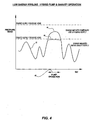
- the operation of the systems shown in Figs. 1 to 3 is shown in the graph of Fig. 4 .
- the graph shows the demand for the majority of the time can be met from the gravity supply pressure head as indicated by line 42. If the demand exceeds the gravity supply pressure head indicated by the plateau indicated by line 44, the option is to either re-schedule the demand so that it does not exceed the gravity pressure head, or alternatively, invoke the pumping systems 34, 36 for this period of time.
- the effect of the invoking of the pumping systems 34, 36 are shown by line 46.
- the time of operation is indicated by arrows 48 on the time line of the graph. This option may also be presented to a user of the system where a higher tariff could be charged if the pump option was selected.
- This invention describes a combined gravity and pressurized pipeline system where the pumped pressure supply is an adjunct to the gravity system and is only invoked when additional pressure head is required.
- the demand management and control system ensures the desired operation of the auxiliary pump facility only during prescribed peak requirements.
Landscapes
- Engineering & Computer Science (AREA)
- Mechanical Engineering (AREA)
- General Engineering & Computer Science (AREA)
- Physics & Mathematics (AREA)
- General Physics & Mathematics (AREA)
- Automation & Control Theory (AREA)
- Fluid Mechanics (AREA)
- Pipeline Systems (AREA)
- Flow Control (AREA)
Claims (5)
- Bewässerungssystem (10) zum Zuführen und Steuern einer Strömungsrate von Bewässerungswasser von einem offenen Kanal (12) in ein mit Schwerkraft betriebenes Rohrleitungsnetz, wobei das System ein Nachfrageverwaltungssystem, um eine Wasserströmungsrate in dem Rohrleitungsnetz zu überwachen, und eine Pumpe (34), um die Wasserströmungsrate zu erhöhen, wenn das Nachfrageverwaltungssystem bestimmt, dass eine Erhöhung der Wasserströmungsrate erforderlich ist, aufweist, wobei das Rohrleitungsnetz ferner mindestens ein Hauptrohr (20) mit mindestens einem Einlass (18) von dem offenen Kanal (12) in das mit Schwerkraft betriebene Rohrleitungsnetz aufweist, wobei das mindestens eine Hauptrohr (20) ferner mindestens ein Wassersteuertor (22), das zwischen einer offenen und einer geschlossenen Position unter Steuerung des Nachfrageverwaltungssystems bewegbar ist, und ein Zweigrohr (30), die zu dem mindestens einen Hauptrohr (20) an einem Ende führt und in eine Quelle (12) von zu pumpendem Wasser an dem anderen Ende öffnet, aufweist, wobei die Pumpe (34) in dem Zweigrohr (30) in dem Pumpmodus Wasser unter Druck in das mindestens eine Hauptrohr (20) zwingt und das Nachfrageverwaltungssystem das mindestens eine Wassersteuertor (22) schließt, während sich die Pumpe (34) in dem Pumpmodus befindet.
- Bewässerungssystem nach Anspruch 1, das ferner einen Durchflussmesser (24) entlang des mindestens einen Hauptrohrs (20) aufweist.
- Bewässerungssystem nach Anspruch 1 oder 2, wobei das Wassersteuertor (22) ein unterschlächtiges Tor ist.
- Bewässerungssystem nach einem der Ansprüche 1 bis 3, das ferner Bewässerungszufuhrpunkte (33) entlang der Länge eines weiteren Rohrs (29), das mit dem mindestens einen Hauptrohr (20) gekoppelt ist, zur Verteilung von Bewässerungswasser an Verbraucher aufweist.
- Bewässerungssystem nach Anspruch 4, wobei jeder der Zufuhrpunkte (33) eine Kombination aus einem Durchflussmesser und einem doppelklappbaren Ventilelement aufweist.
Applications Claiming Priority (3)
| Application Number | Priority Date | Filing Date | Title |
|---|---|---|---|
| AU2012905225A AU2012905225A0 (en) | 2012-11-30 | Gravity Fed Pipeline System for Fluids | |
| AU2012905508A AU2012905508A0 (en) | 2012-12-17 | Pipeline system for fluids | |
| PCT/AU2013/001368 WO2014082121A1 (en) | 2012-11-30 | 2013-11-26 | Pipeline system for fluids |
Publications (3)
| Publication Number | Publication Date |
|---|---|
| EP2926207A1 EP2926207A1 (de) | 2015-10-07 |
| EP2926207A4 EP2926207A4 (de) | 2016-08-31 |
| EP2926207B1 true EP2926207B1 (de) | 2021-07-21 |
Family
ID=50826954
Family Applications (1)
| Application Number | Title | Priority Date | Filing Date |
|---|---|---|---|
| EP13858462.8A Active EP2926207B1 (de) | 2012-11-30 | 2013-11-26 | Rohrleitungssystem für flüssigkeiten |
Country Status (8)
| Country | Link |
|---|---|
| US (1) | US10578112B2 (de) |
| EP (1) | EP2926207B1 (de) |
| CN (2) | CN107489888B (de) |
| AU (1) | AU2013351909B2 (de) |
| BR (1) | BR112015012676B1 (de) |
| ES (1) | ES2893248T3 (de) |
| MX (1) | MX376825B (de) |
| WO (1) | WO2014082121A1 (de) |
Families Citing this family (5)
| Publication number | Priority date | Publication date | Assignee | Title |
|---|---|---|---|---|
| AU2013205195B2 (en) | 2013-04-14 | 2015-07-09 | Rubicon Research Pty Ltd | Valve |
| CN105612289A (zh) | 2013-09-04 | 2016-05-25 | 鲁比康研究有限公司 | 流体管道网络的需求管理和控制的方法 |
| FI12191U1 (fi) * | 2018-06-27 | 2018-10-15 | Paradise Honey Oy | Mehiläisvahan erotusruuvin hunajavahaseoksen ahdin |
| WO2020097203A1 (en) * | 2018-11-06 | 2020-05-14 | IoT Diagnostics | Fluid efficency of a fluid |
| US11109543B2 (en) * | 2019-12-05 | 2021-09-07 | Shun-Tsung Lu | Soil irrigation and restoration method and system of the same |
Citations (1)
| Publication number | Priority date | Publication date | Assignee | Title |
|---|---|---|---|---|
| US20040027020A1 (en) * | 2002-08-08 | 2004-02-12 | Newcomb Ronald A. | Electro-magnetic archimedean screw motor-generator |
Family Cites Families (20)
| Publication number | Priority date | Publication date | Assignee | Title |
|---|---|---|---|---|
| US2984986A (en) * | 1957-12-06 | 1961-05-23 | Raymond A Hill | Automatically controlled hydraulic gate and gate control |
| JPS5350863A (en) * | 1976-10-20 | 1978-05-09 | Hitachi Ltd | Demand quantity estimating apparatus for flow rate pressure controlling in piping network |
| US4209131A (en) | 1978-05-12 | 1980-06-24 | Motorola, Inc. | Computer-controlled irrigation system |
| US4381645A (en) * | 1981-01-05 | 1983-05-03 | Galuska Charles W | Power unit for dam |
| US4867192A (en) * | 1989-02-03 | 1989-09-19 | Terrell B Joe | Apparatus for controlling irrigation water pH for golf courses |
| IT1272103B (it) * | 1993-03-17 | 1997-06-11 | I A S Ind Automation Systems A | Apparecchiatura per l'erogazione di una sostanza fluida,in quantita' dosate |
| US5788466A (en) * | 1996-07-01 | 1998-08-04 | Thompson; Andy L. | Irrigation booster pump system |
| JPH11212653A (ja) * | 1998-01-21 | 1999-08-06 | Fujikin Inc | 流体供給装置 |
| US20020187054A1 (en) * | 1999-11-22 | 2002-12-12 | Eller Dana J. | Electric pumping apparatus with extendable drawing pipe and pump light tower |
| AUPR353801A0 (en) | 2001-03-02 | 2001-03-29 | Rubicon Systems Australia Pty Ltd | Fluid regulation |
| CN2624611Y (zh) * | 2003-06-26 | 2004-07-14 | 蒲朝岗 | 一种新型农田灌溉系统 |
| WO2006014372A2 (en) * | 2004-07-02 | 2006-02-09 | Ferber Philip E | Pipeline flow control optimization software, and methods |
| US7647136B2 (en) * | 2006-09-28 | 2010-01-12 | Exxonmobil Research And Engineering Company | Method and apparatus for enhancing operation of a fluid transport pipeline |
| CN100591203C (zh) * | 2006-10-27 | 2010-02-24 | 梁耀德 | 灌溉系统 |
| US8007249B2 (en) * | 2007-06-20 | 2011-08-30 | Spargo Rick D | Tile flood pump |
| US7632040B2 (en) * | 2007-10-30 | 2009-12-15 | Criptonic Energy Solutions, Inc. | Waste water electrical power generating system with storage system and methods for use therewith |
| CN201226701Y (zh) * | 2008-04-30 | 2009-04-29 | 东莞市农业种子研究所 | 低压节水灌溉系统 |
| CN101336603B (zh) * | 2008-07-25 | 2011-01-19 | 中国科学院遗传与发育生物学研究所 | 大田小定额灌溉系统 |
| GB0914839D0 (en) * | 2009-08-26 | 2009-09-30 | Proflux Systems Llp | Treatment of oil |
| US9563207B2 (en) * | 2011-08-02 | 2017-02-07 | Rubicon Research Pty Ltd | Demand management system for fluid networks |
-
2013
- 2013-11-26 CN CN201710734061.4A patent/CN107489888B/zh active Active
- 2013-11-26 AU AU2013351909A patent/AU2013351909B2/en active Active
- 2013-11-26 US US14/648,689 patent/US10578112B2/en active Active
- 2013-11-26 EP EP13858462.8A patent/EP2926207B1/de active Active
- 2013-11-26 CN CN201380069194.4A patent/CN105009015A/zh active Pending
- 2013-11-26 MX MX2015006827A patent/MX376825B/es active IP Right Grant
- 2013-11-26 ES ES13858462T patent/ES2893248T3/es active Active
- 2013-11-26 WO PCT/AU2013/001368 patent/WO2014082121A1/en not_active Ceased
- 2013-11-26 BR BR112015012676-6A patent/BR112015012676B1/pt active IP Right Grant
Patent Citations (1)
| Publication number | Priority date | Publication date | Assignee | Title |
|---|---|---|---|---|
| US20040027020A1 (en) * | 2002-08-08 | 2004-02-12 | Newcomb Ronald A. | Electro-magnetic archimedean screw motor-generator |
Also Published As
| Publication number | Publication date |
|---|---|
| BR112015012676A2 (pt) | 2017-07-11 |
| CN107489888A (zh) | 2017-12-19 |
| US10578112B2 (en) | 2020-03-03 |
| EP2926207A4 (de) | 2016-08-31 |
| BR112015012676B1 (pt) | 2022-05-31 |
| CN107489888B (zh) | 2020-05-01 |
| US20150301534A1 (en) | 2015-10-22 |
| MX376825B (es) | 2025-03-07 |
| ES2893248T3 (es) | 2022-02-08 |
| EP2926207A1 (de) | 2015-10-07 |
| WO2014082121A1 (en) | 2014-06-05 |
| AU2013351909A1 (en) | 2015-06-18 |
| MX2015006827A (es) | 2016-01-14 |
| CN105009015A (zh) | 2015-10-28 |
| AU2013351909B2 (en) | 2017-09-07 |
Similar Documents
| Publication | Publication Date | Title |
|---|---|---|
| EP2926207B1 (de) | Rohrleitungssystem für flüssigkeiten | |
| US7957841B2 (en) | Method of calculating pump flow rates and an automated pump control system | |
| US11629889B2 (en) | Geothermal heat utilization system and geothermal heat utilization method | |
| EP4020790A1 (de) | Wasserkrafterzeugungssystem und stromgeneratorsteuerungsverfahren | |
| US20090016901A1 (en) | Self-priming electronic metering pump and priming methodology | |
| CN104736858A (zh) | 带动态密封件的液压系统 | |
| CN109681474A (zh) | 一种抑制离心泵空化的自动调节装置及方法 | |
| KR101992765B1 (ko) | 역류방지 하이브리드 급수 시스템 및 그 제어방법 | |
| KR101292969B1 (ko) | 지하수 모니터링장치 | |
| CN100540966C (zh) | 补充供水控制器、用于补充干线供水的系统和方法 | |
| HU227734B1 (en) | Pump station | |
| US9528607B2 (en) | Stuffing box flow diverter and methods therefor | |
| KR101810232B1 (ko) | 작동 이상을 실시간 감지 가능한 부스터 펌프용 유량 센서 및 부스터 펌프 시스템 | |
| EP2610501B1 (de) | Verfahren zum Anhalten einer Hydraulikpumpe mit anpassbarer Rotationsgeschwindigkeit in einem Hydrauliksystem und Hydraulikpumpensteuerungsvorrichtung | |
| CN210623064U (zh) | 智能砼泵冷却液补充装置 | |
| CN103696998A (zh) | 静液压传动装置检测平台负载系统 | |
| CN220059872U (zh) | 柱塞填料检漏结构及往复式柱塞泵系统 | |
| CN220667984U (zh) | 一种油泵检测用液压系统 | |
| CN106103997B (zh) | 供泵抽装置的流量控制系统 | |
| EP4497950A1 (de) | Verfahren zur schätzung der ausgangsdurchflusses einer pumpe | |
| CN217977542U (zh) | 一种具有换向结构的水流阀门 | |
| CN216554656U (zh) | 一种液压系统及工程机械 | |
| CN203730422U (zh) | 静液压传动装置检测平台负载系统 | |
| AU2013205704B2 (en) | Water supply system utilizing collected stored water and mains water supply | |
| CN118088404A (zh) | 用于泵送设备的闭式液压系统和泵送设备 |
Legal Events
| Date | Code | Title | Description |
|---|---|---|---|
| PUAI | Public reference made under article 153(3) epc to a published international application that has entered the european phase |
Free format text: ORIGINAL CODE: 0009012 |
|
| 17P | Request for examination filed |
Effective date: 20150626 |
|
| AK | Designated contracting states |
Kind code of ref document: A1 Designated state(s): AL AT BE BG CH CY CZ DE DK EE ES FI FR GB GR HR HU IE IS IT LI LT LU LV MC MK MT NL NO PL PT RO RS SE SI SK SM TR |
|
| AX | Request for extension of the european patent |
Extension state: BA ME |
|
| DAX | Request for extension of the european patent (deleted) | ||
| RA4 | Supplementary search report drawn up and despatched (corrected) |
Effective date: 20160802 |
|
| RIC1 | Information provided on ipc code assigned before grant |
Ipc: G05D 7/00 20060101AFI20160727BHEP Ipc: F17D 5/02 20060101ALI20160727BHEP Ipc: G01M 3/28 20060101ALI20160727BHEP Ipc: G05D 16/00 20060101ALI20160727BHEP Ipc: G05D 7/06 20060101ALI20160727BHEP Ipc: G05D 16/20 20060101ALI20160727BHEP Ipc: F04C 2/16 20060101ALI20160727BHEP |
|
| STAA | Information on the status of an ep patent application or granted ep patent |
Free format text: STATUS: EXAMINATION IS IN PROGRESS |
|
| 17Q | First examination report despatched |
Effective date: 20191004 |
|
| REG | Reference to a national code |
Ref country code: DE Ref legal event code: R079 Ref document number: 602013078479 Country of ref document: DE Free format text: PREVIOUS MAIN CLASS: G05D0007000000 Ipc: G05D0007060000 |
|
| RIC1 | Information provided on ipc code assigned before grant |
Ipc: G01M 3/28 20060101ALI20210324BHEP Ipc: F17D 3/01 20060101ALI20210324BHEP Ipc: F17D 1/20 20060101ALI20210324BHEP Ipc: G05D 7/06 20060101AFI20210324BHEP |
|
| GRAP | Despatch of communication of intention to grant a patent |
Free format text: ORIGINAL CODE: EPIDOSNIGR1 |
|
| STAA | Information on the status of an ep patent application or granted ep patent |
Free format text: STATUS: GRANT OF PATENT IS INTENDED |
|
| INTG | Intention to grant announced |
Effective date: 20210504 |
|
| GRAS | Grant fee paid |
Free format text: ORIGINAL CODE: EPIDOSNIGR3 |
|
| GRAA | (expected) grant |
Free format text: ORIGINAL CODE: 0009210 |
|
| STAA | Information on the status of an ep patent application or granted ep patent |
Free format text: STATUS: THE PATENT HAS BEEN GRANTED |
|
| AK | Designated contracting states |
Kind code of ref document: B1 Designated state(s): AL AT BE BG CH CY CZ DE DK EE ES FI FR GB GR HR HU IE IS IT LI LT LU LV MC MK MT NL NO PL PT RO RS SE SI SK SM TR |
|
| REG | Reference to a national code |
Ref country code: GB Ref legal event code: FG4D |
|
| REG | Reference to a national code |
Ref country code: CH Ref legal event code: EP |
|
| REG | Reference to a national code |
Ref country code: DE Ref legal event code: R096 Ref document number: 602013078479 Country of ref document: DE |
|
| REG | Reference to a national code |
Ref country code: AT Ref legal event code: REF Ref document number: 1413165 Country of ref document: AT Kind code of ref document: T Effective date: 20210815 |
|
| REG | Reference to a national code |
Ref country code: IE Ref legal event code: FG4D |
|
| REG | Reference to a national code |
Ref country code: LT Ref legal event code: MG9D |
|
| REG | Reference to a national code |
Ref country code: NL Ref legal event code: MP Effective date: 20210721 |
|
| REG | Reference to a national code |
Ref country code: AT Ref legal event code: MK05 Ref document number: 1413165 Country of ref document: AT Kind code of ref document: T Effective date: 20210721 |
|
| PG25 | Lapsed in a contracting state [announced via postgrant information from national office to epo] |
Ref country code: HR Free format text: LAPSE BECAUSE OF FAILURE TO SUBMIT A TRANSLATION OF THE DESCRIPTION OR TO PAY THE FEE WITHIN THE PRESCRIBED TIME-LIMIT Effective date: 20210721 Ref country code: RS Free format text: LAPSE BECAUSE OF FAILURE TO SUBMIT A TRANSLATION OF THE DESCRIPTION OR TO PAY THE FEE WITHIN THE PRESCRIBED TIME-LIMIT Effective date: 20210721 Ref country code: SE Free format text: LAPSE BECAUSE OF FAILURE TO SUBMIT A TRANSLATION OF THE DESCRIPTION OR TO PAY THE FEE WITHIN THE PRESCRIBED TIME-LIMIT Effective date: 20210721 Ref country code: FI Free format text: LAPSE BECAUSE OF FAILURE TO SUBMIT A TRANSLATION OF THE DESCRIPTION OR TO PAY THE FEE WITHIN THE PRESCRIBED TIME-LIMIT Effective date: 20210721 Ref country code: NL Free format text: LAPSE BECAUSE OF FAILURE TO SUBMIT A TRANSLATION OF THE DESCRIPTION OR TO PAY THE FEE WITHIN THE PRESCRIBED TIME-LIMIT Effective date: 20210721 Ref country code: NO Free format text: LAPSE BECAUSE OF FAILURE TO SUBMIT A TRANSLATION OF THE DESCRIPTION OR TO PAY THE FEE WITHIN THE PRESCRIBED TIME-LIMIT Effective date: 20211021 Ref country code: PT Free format text: LAPSE BECAUSE OF FAILURE TO SUBMIT A TRANSLATION OF THE DESCRIPTION OR TO PAY THE FEE WITHIN THE PRESCRIBED TIME-LIMIT Effective date: 20211122 Ref country code: AT Free format text: LAPSE BECAUSE OF FAILURE TO SUBMIT A TRANSLATION OF THE DESCRIPTION OR TO PAY THE FEE WITHIN THE PRESCRIBED TIME-LIMIT Effective date: 20210721 Ref country code: BG Free format text: LAPSE BECAUSE OF FAILURE TO SUBMIT A TRANSLATION OF THE DESCRIPTION OR TO PAY THE FEE WITHIN THE PRESCRIBED TIME-LIMIT Effective date: 20211021 Ref country code: LT Free format text: LAPSE BECAUSE OF FAILURE TO SUBMIT A TRANSLATION OF THE DESCRIPTION OR TO PAY THE FEE WITHIN THE PRESCRIBED TIME-LIMIT Effective date: 20210721 |
|
| REG | Reference to a national code |
Ref country code: ES Ref legal event code: FG2A Ref document number: 2893248 Country of ref document: ES Kind code of ref document: T3 Effective date: 20220208 |
|
| PG25 | Lapsed in a contracting state [announced via postgrant information from national office to epo] |
Ref country code: PL Free format text: LAPSE BECAUSE OF FAILURE TO SUBMIT A TRANSLATION OF THE DESCRIPTION OR TO PAY THE FEE WITHIN THE PRESCRIBED TIME-LIMIT Effective date: 20210721 Ref country code: LV Free format text: LAPSE BECAUSE OF FAILURE TO SUBMIT A TRANSLATION OF THE DESCRIPTION OR TO PAY THE FEE WITHIN THE PRESCRIBED TIME-LIMIT Effective date: 20210721 Ref country code: GR Free format text: LAPSE BECAUSE OF FAILURE TO SUBMIT A TRANSLATION OF THE DESCRIPTION OR TO PAY THE FEE WITHIN THE PRESCRIBED TIME-LIMIT Effective date: 20211022 |
|
| REG | Reference to a national code |
Ref country code: DE Ref legal event code: R097 Ref document number: 602013078479 Country of ref document: DE |
|
| PG25 | Lapsed in a contracting state [announced via postgrant information from national office to epo] |
Ref country code: DK Free format text: LAPSE BECAUSE OF FAILURE TO SUBMIT A TRANSLATION OF THE DESCRIPTION OR TO PAY THE FEE WITHIN THE PRESCRIBED TIME-LIMIT Effective date: 20210721 |
|
| PLBE | No opposition filed within time limit |
Free format text: ORIGINAL CODE: 0009261 |
|
| STAA | Information on the status of an ep patent application or granted ep patent |
Free format text: STATUS: NO OPPOSITION FILED WITHIN TIME LIMIT |
|
| PG25 | Lapsed in a contracting state [announced via postgrant information from national office to epo] |
Ref country code: SM Free format text: LAPSE BECAUSE OF FAILURE TO SUBMIT A TRANSLATION OF THE DESCRIPTION OR TO PAY THE FEE WITHIN THE PRESCRIBED TIME-LIMIT Effective date: 20210721 Ref country code: SK Free format text: LAPSE BECAUSE OF FAILURE TO SUBMIT A TRANSLATION OF THE DESCRIPTION OR TO PAY THE FEE WITHIN THE PRESCRIBED TIME-LIMIT Effective date: 20210721 Ref country code: RO Free format text: LAPSE BECAUSE OF FAILURE TO SUBMIT A TRANSLATION OF THE DESCRIPTION OR TO PAY THE FEE WITHIN THE PRESCRIBED TIME-LIMIT Effective date: 20210721 Ref country code: EE Free format text: LAPSE BECAUSE OF FAILURE TO SUBMIT A TRANSLATION OF THE DESCRIPTION OR TO PAY THE FEE WITHIN THE PRESCRIBED TIME-LIMIT Effective date: 20210721 Ref country code: CZ Free format text: LAPSE BECAUSE OF FAILURE TO SUBMIT A TRANSLATION OF THE DESCRIPTION OR TO PAY THE FEE WITHIN THE PRESCRIBED TIME-LIMIT Effective date: 20210721 Ref country code: AL Free format text: LAPSE BECAUSE OF FAILURE TO SUBMIT A TRANSLATION OF THE DESCRIPTION OR TO PAY THE FEE WITHIN THE PRESCRIBED TIME-LIMIT Effective date: 20210721 |
|
| REG | Reference to a national code |
Ref country code: DE Ref legal event code: R119 Ref document number: 602013078479 Country of ref document: DE |
|
| 26N | No opposition filed |
Effective date: 20220422 |
|
| PG25 | Lapsed in a contracting state [announced via postgrant information from national office to epo] |
Ref country code: MC Free format text: LAPSE BECAUSE OF FAILURE TO SUBMIT A TRANSLATION OF THE DESCRIPTION OR TO PAY THE FEE WITHIN THE PRESCRIBED TIME-LIMIT Effective date: 20210721 |
|
| REG | Reference to a national code |
Ref country code: CH Ref legal event code: PL |
|
| GBPC | Gb: european patent ceased through non-payment of renewal fee |
Effective date: 20211126 |
|
| PG25 | Lapsed in a contracting state [announced via postgrant information from national office to epo] |
Ref country code: LU Free format text: LAPSE BECAUSE OF NON-PAYMENT OF DUE FEES Effective date: 20211126 Ref country code: BE Free format text: LAPSE BECAUSE OF NON-PAYMENT OF DUE FEES Effective date: 20211130 |
|
| REG | Reference to a national code |
Ref country code: BE Ref legal event code: MM Effective date: 20211130 |
|
| PG25 | Lapsed in a contracting state [announced via postgrant information from national office to epo] |
Ref country code: LI Free format text: LAPSE BECAUSE OF NON-PAYMENT OF DUE FEES Effective date: 20211130 Ref country code: CH Free format text: LAPSE BECAUSE OF NON-PAYMENT OF DUE FEES Effective date: 20211130 |
|
| PG25 | Lapsed in a contracting state [announced via postgrant information from national office to epo] |
Ref country code: IE Free format text: LAPSE BECAUSE OF NON-PAYMENT OF DUE FEES Effective date: 20211126 Ref country code: GB Free format text: LAPSE BECAUSE OF NON-PAYMENT OF DUE FEES Effective date: 20211126 Ref country code: DE Free format text: LAPSE BECAUSE OF NON-PAYMENT OF DUE FEES Effective date: 20220601 |
|
| PG25 | Lapsed in a contracting state [announced via postgrant information from national office to epo] |
Ref country code: FR Free format text: LAPSE BECAUSE OF NON-PAYMENT OF DUE FEES Effective date: 20211130 |
|
| PG25 | Lapsed in a contracting state [announced via postgrant information from national office to epo] |
Ref country code: HU Free format text: LAPSE BECAUSE OF FAILURE TO SUBMIT A TRANSLATION OF THE DESCRIPTION OR TO PAY THE FEE WITHIN THE PRESCRIBED TIME-LIMIT; INVALID AB INITIO Effective date: 20131126 |
|
| PG25 | Lapsed in a contracting state [announced via postgrant information from national office to epo] |
Ref country code: CY Free format text: LAPSE BECAUSE OF FAILURE TO SUBMIT A TRANSLATION OF THE DESCRIPTION OR TO PAY THE FEE WITHIN THE PRESCRIBED TIME-LIMIT Effective date: 20210721 |
|
| P01 | Opt-out of the competence of the unified patent court (upc) registered |
Effective date: 20230602 |
|
| PG25 | Lapsed in a contracting state [announced via postgrant information from national office to epo] |
Ref country code: MK Free format text: LAPSE BECAUSE OF FAILURE TO SUBMIT A TRANSLATION OF THE DESCRIPTION OR TO PAY THE FEE WITHIN THE PRESCRIBED TIME-LIMIT Effective date: 20210721 |
|
| PG25 | Lapsed in a contracting state [announced via postgrant information from national office to epo] |
Ref country code: TR Free format text: LAPSE BECAUSE OF FAILURE TO SUBMIT A TRANSLATION OF THE DESCRIPTION OR TO PAY THE FEE WITHIN THE PRESCRIBED TIME-LIMIT Effective date: 20210721 |
|
| PG25 | Lapsed in a contracting state [announced via postgrant information from national office to epo] |
Ref country code: MT Free format text: LAPSE BECAUSE OF FAILURE TO SUBMIT A TRANSLATION OF THE DESCRIPTION OR TO PAY THE FEE WITHIN THE PRESCRIBED TIME-LIMIT Effective date: 20210721 |
|
| PGFP | Annual fee paid to national office [announced via postgrant information from national office to epo] |
Ref country code: IT Payment date: 20251127 Year of fee payment: 13 |
|
| PGFP | Annual fee paid to national office [announced via postgrant information from national office to epo] |
Ref country code: ES Payment date: 20260226 Year of fee payment: 13 |