EP2926876A1 - Vis de réglage avec rainure de came circulaire - Google Patents
Vis de réglage avec rainure de came circulaire Download PDFInfo
- Publication number
- EP2926876A1 EP2926876A1 EP15161145.6A EP15161145A EP2926876A1 EP 2926876 A1 EP2926876 A1 EP 2926876A1 EP 15161145 A EP15161145 A EP 15161145A EP 2926876 A1 EP2926876 A1 EP 2926876A1
- Authority
- EP
- European Patent Office
- Prior art keywords
- adjusting
- coupling member
- holding unit
- adjusting device
- shoe
- Prior art date
- Legal status (The legal status is an assumption and is not a legal conclusion. Google has not performed a legal analysis and makes no representation as to the accuracy of the status listed.)
- Granted
Links
Images



Classifications
-
- A—HUMAN NECESSITIES
- A63—SPORTS; GAMES; AMUSEMENTS
- A63C—SKATES; SKIS; ROLLER SKATES; DESIGN OR LAYOUT OF COURTS, RINKS OR THE LIKE
- A63C9/00—Ski bindings
- A63C9/08—Ski bindings yieldable or self-releasing in the event of an accident, i.e. safety bindings
- A63C9/0805—Adjustment of the toe or heel holders; Indicators therefor
-
- A—HUMAN NECESSITIES
- A63—SPORTS; GAMES; AMUSEMENTS
- A63C—SKATES; SKIS; ROLLER SKATES; DESIGN OR LAYOUT OF COURTS, RINKS OR THE LIKE
- A63C9/00—Ski bindings
- A63C9/24—Tighteners for ski bindings
Definitions
- the invention relates to an adjusting device for adjusting the release force of a compression spring on a shoe holding unit of a ski binding, such as a toe holder or a heel holder.
- the adjusting device comprises, in addition to the compression spring, an adjusting member and a coupling member which is arranged between the compression spring and the adjusting member.
- the compression spring For the user of a ski, it is important to know what value the compression spring is set, since this value determines the triggering force, which must be overcome in the case of, for example, a fall, to separate the ski from the ski boot and thus the risk of injury to the ski Reduce users.
- the release force depends on several factors, such as the weight of the user, their ability, the condition of the runway, etc.
- the shoe holding units In order to read the set value of the release force, the shoe holding units usually have a window through which the set release force a scale can be read. Since small changes to the compression of the compression spring sufficient to achieve a necessary adjustment of the trigger value, the set trigger value on the scale is usually very difficult to read, since the numbers on the scale are written very small and / or very close to each other.
- One aspect of the invention relates to an adjusting device for adjusting the release force of a compression spring on a shoe holding unit, with a compression spring, an adjusting member and a coupling member which is arranged between the compression spring and the adjusting member.
- the coupling member has on its side facing the adjusting member at least one curved path and the adjusting member has on its side facing the coupling member at least one curved path.
- one of the cam tracks may be a guide track which increases in the circumferential direction of the adjusting member or the coupling member, in the other cam track around an engaging member, for example in the form of a cam.
- the adjusting member and / or the coupling member may be formed of a metal or a hard, non-elastically deformable plastic.
- the adjusting member and / or the coupling member may each be formed in one piece, for example in a casting or sintering process or by a machining operation.
- the adjusting member and the coupling member may have a common axis of rotation or the axis of rotation of the coupling member extends at least substantially parallel to the axis of rotation of the adjusting member.
- the axis of rotation can extend at least in a plan view from above substantially parallel, or transversely to a longitudinal central axis of the bond
- the adjusting member may, for example, have a mushroom shape, with a hollow cylindrical cap having a substantially closed surface.
- an engagement may be formed for a tool, for example, a flat-head screwdriver, a Phillips screwdriver, a hex key or a key with any other form of engagement.
- the tool engagement is accessible from the outside when installed in a shoe holding device adjustment for a user or a service person, so that he can set a value of the release force of the compression spring by means of the tool.
- the hollow cylindrical cap may have a corrugation on its outer circumference, the corrugation may preferably have a gear-like structure, with Teeth which are formed in the direction of a longitudinal axis of the cap over at least a part of the cap and in the circumferential direction over at least part of the circumference.
- From the hollow cylindrical cap may protrude a cylindrical or hollow cylindrical foot, with a diameter which is smaller than a diameter of the cap itself, so that between the cylinder inner wall of the cap and the cylinder outer wall of the foot, a gap is formed.
- the at least one curved path of the adjusting member may in particular be formed in a ramp-like or helical step shape and rise in a circumferential direction of the adjusting member.
- the cam track may be disposed on the adjusting member in the above-described gap between the inner wall of the cap and the outer wall of the foot.
- the cam track can be formed, in particular, on an underside of the closed surface of the cap facing the coupling element.
- the curved path may have a part-circular shape, viewed from one side, the ramp or "spiral staircase" rises steadily or step-like.
- the at least one curved path of the coupling member may be formed arm-shaped or formed by a cam and protrude from the coupling member in the direction of the adjusting member.
- the arm / cam can also be formed part-circular in a plan view.
- the adjusting member may be rotatably guided in an opening of the coupling member and the arm may form part of the rotary guide.
- the already described above foot of the adjusting member is a guide cylinder which projects in the direction of the coupling member on the cam track of the adjusting member and can be at least partially encompassed on the outside of the arm of the coupling member for rotating the adjusting member in the coupling member.
- the cam track, respectively the arm, of the coupling member engages in the gap between the inner wall of the cap and the outer wall of the guide cylinder.
- a free end of the arm abuts the underside of the surface of the cap.
- At least one step may be formed on a flank, in which each step of the at least one curved track of the engaging member may engage with rotation of the engaging member relative to the coupling member.
- the locking has the advantage that the adjusting member from the set position can not easily move out on its own, another advantage may be that the adjusting member generates an audible clicking sound when snapped, which gives the user the security that the adjusting member in the safe latched position and at the same time allows to count the number of clicks, so as easy, fast and safe to set a triggering force.
- the at least one curved path of the adjusting member can move along a twisting of the adjusting member along the curved path of the coupling member, and vice versa.
- the curved paths may be formed in a ramp shape, with a continuous, smooth track surface, that is, without steps.
- the cap of the adjusting member may have on its outer side a gear-like configuration with teeth that extend at least partially over an axial length and at least partially over the circumference of the cap.
- the teeth may form engagement elements which cooperate with counter-engagement elements connected to the shoe-holding unit.
- the counter-engagement element may be elastically formed or spring-mounted, so that the engagement elements can displace the counter-engagement elements during rotation of the cap. Engagement elements and mating engagement elements can lock together to prevent accidental rotation of the adjustment during transport or operation of the ski.
- two, three or more cam tracks may be formed on the adjusting member and a corresponding number of curved tracks on the coupling member.
- these multiple curved paths can be identical curved paths, ie identical ramps or "spiral staircases" and identical arms / cams.
- the provision of more than one curved path has the advantage that touch the adjusting member and the coupling member in more than one line or surface, which prevents the two parts tilt against each other or must be designed to set very high release forces accordingly solid.
- the plurality of "spiral staircases" may have different step heights and / or the at least one step may be formed on each of the plurality of arms on its flank at different locations. As a result, a finer adjustment of the release force of the compression spring can be achieved.
- the adjusting member and the coupling member each have two curved paths, preferably two identical curved tracks, they may be arranged opposite each other with respect to a plane through a rotation axis of the adjusting member and the coupling member.
- the compression spring is supported in the installed state in the shoe holding unit with one side on at least one other intermediate links, for example the coupling member, on the adjusting member and with the other side on an element or part of the shoe holding unit.
- the compression spring is supported on one side on the coupling member and on the other side on a sole holder of the heel holder or a vending machine of the heel holder or on the / n sole holders of the toe holder.
- the adjusting member may be connected to a scale or has a scale which is visible in the shoe-holding unit, for example through an opening or a window, preferably only a part of the scale is visible in the window.
- the scale may have consecutive numbers from 0 to 9, of which only a single number may ever be visible through the aperture or window.
- the readable number is then a trigger value of the compression spring.
- a table from the assignment of a triggering force to the each number can be seen, may be located at a suitable location on the shoe holding member.
- other symbols such as color code or pictograms, can be used to indicate to the user the set release force.
- the numbers or symbols can be rendered large enough to be easily read by the user.
- a magnifying glass can be arranged in the opening to further facilitate the reading.
- the space may extend from a centerline through a first number to the centerline of the subsequent number.
- the coupling member may have on its side facing the opening or the window side a visual sign, for example an arrow, which always points to the currently set trigger value on the scale. This facilitates the reading of the set value, in particular in the case of the division of the space between two symbols on the scale.
- the visual indicium may be printed, raised, or integrally molded with the coupling member, the window, or another portion of the shoe-holding assembly housing.
- a scale may also be connected to the coupling member, for example in the form of a rod extending substantially parallel to the first from the coupling member in the direction of the compression spring Rotary axis of the adjusting member projects and is firmly connected to the coupling member.
- the rod is linearly moved with the scale under an opening or window in the shoe support assembly so that it always passes through the aperture or window the set value of the release force of the compression spring is readable.
- the opening, window and scale are the same as described in the previous paragraph.
- a second aspect of the invention relates to a shoe holding unit of a ski or snowboard binding with the adjustment device described above.
- the shoe-holding unit supports the adjusting member rotatable relative to the shoe-holding unit or the binding about a rotation axis parallel or transversely to a longitudinal axis of the shoe-holding unit, but linearly stationary.
- the shoe holding unit supports the coupling member relative to the shoe holding unit rotatably but linearly movable.
- the compression spring is supported with at least one end on a part of the shoe holding unit and with one end on the coupling member.
- the compression spring is supported in a known toe holder with two pivoting about an axis perpendicular to the surface of the ski or the snowboard sole holders on each of the two sole holders, with one end directly and with the other over at least part of the adjustment.
- the compression spring is supported at one end on the machine and at the other end on the setting device.
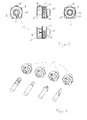
- FIG. 1 shows the three essential parts of an embodiment of an adjusting device 1 according to the invention, but without the compression spring 11 (see FIG. 5 ).
- the adjusting device 1 comprises a coupling member 3 having a coupling member body 3a, two arms 5 projecting axially from the coupling member body 3a and having a cam track 5a, the two arms 5 and the cam tracks 5a being identical in the embodiment are executed.
- the cam tracks 5a have two flanks 5b and 5c, the flanks 5b having a step 9.
- the coupling member 3 has a non-circular periphery and at its in the FIG. 1 upper side a visual display 12 in the form of an arrow or pointer. Furthermore, the coupling member 3 has an opening 7, in the embodiment, a central opening 7.
- the coupling member 3, that is, the coupling member body 3a, the arms 5 with the cam tracks 5a, and the visual display 12 are molded in one piece, for example, by a casting or sintering method.
- an adjusting member 2 which comprises an engagement portion 13 for a tool, a cylindrical cap 14 and a guide cylinder 15.
- a diameter of the cap 14 is larger than a diameter of the guide cylinder 15.
- a knob 16 is arranged, the meaning of which will become clear later.
- a groove 14 a is formed, which can accommodate, for example, a scale 10.
- the guide cylinder 15 has a diameter which substantially corresponds to a diameter of the opening 7 of the coupling member 3 on a side facing the adjusting member 2.
- the adjusting member 2 that is, the engaging portion 13, the cap 14, the guide cylinder 15 and the nubs 16 are molded in one piece, for example, by a casting or sintering method.
- FIG. 1 shows the scale 10, which can be connected to an outer side of the cap 14 in the groove 14 a, for example plugged or glued.
- the adjusting device 1 comprises a compression spring 11, which in the FIG. 5 is shown.
- FIG. 2 shows the adjusting device 1 of FIG. 1 without scale 10 in a view that allows insight into the setting member 2.
- Both the cap 14 and the Guide cylinder 15 are formed as a hollow cylinder. Between an inside of the cap 14 and the outside of the guide cylinder 15, a gap 17 is formed. In the gap 17, two cam tracks 4 are arranged, which are formed spiral staircase with steps 8 and project from an inner bottom of the cap 14 in the direction of the coupling member 3.
- this has a first portion 3b with a first diameter, in which the compression spring 11, not shown (see FIG. 5 ) and a second portion 3c having a second diameter smaller than the first diameter forming a guide for the guide cylinder 15 of the adjusting member 2.
- FIG. 3 shows the assembled adjustment 1 without compression spring 11 in four views: a view of the adjusting member 2, a view of the adjusting device 1 from one side, a view of the coupling member 3 and a view of the adjusting device 1 from above.
- the four views do not show anything unwilling FIGS. 1 and 3 is known.
- FIG. 4 shows the adjusting device 1 with engagement portions 13 for different tools, and the associated bits or tool heads.
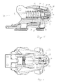
- FIG. 5 shows in an axial section a side view of a shoe holding unit 20.
- the adjustment device 1 is installed.
- the adjusting member 2 respectively the engaging portion 13 protrudes from the shoe holding unit housing 21, respectively, terminates flush with an outer side of the shoe holding unit housing 21.
- the adjoining the engagement portion 13 region of the top of the cap 14 abuts an inner side of the shoe holding unit housing 21 and is pressed by the compression spring 11 against this inside.
- a circumferential groove 22 is formed, which is a rotary guide for the nubs 16 (see FIG. 1 ) of the adjusting member 2 forms.
- the engagement member 2 comprises the cap 14 and the guide cylinder 15, both of which are formed as a hollow cylinder.
- the coupling member 3 engages with the arms 5 in the gap 17 between the inside of the cap 14 and the outside of the guide cylinder 15 and is in the embodiment of the inside of the bottom of the cap 14 at. That is, illustrated is the situation in which the scale 10 indicates a minimum value.
- the guide cylinder 15 extends through the opening 7 of the coupling member 3 and extends into the compression spring eleventh
- the compression spring 11 engages in the first portion 3b of the coupling member 3 and lies in a gap 18 which is formed by an inner side of the first portion 3b and the outer side of the guide cylinder 15.
- the compression spring presses the coupling member against the adjusting member 2, respectively the cam tracks 5a of the arms 5 against the cam tracks 4, so that upon rotation of the adjusting member 2, the rampen or helical cam tracks 4 on the cam tracks 5a, the coupling member will move linearly and thereby the compression spring 11 compress. Due to the interaction of the two cam tracks 4 and 5 a, a small rotation on the adjusting member 2 leads to a greater linear movement of the coupling member 3.
- the compression spring 11, the coupling member 3 and the adjusting member 2 are arranged coaxially in the embodiment, with the common axis, which is the axis of rotation R of the adjusting member 2.
- FIG. 6 shows the shoe holding unit 20 of FIG. 5 from above. Parts of the adjusting member 2 with the scale 10 and parts of the coupling member 3 with the visual display 12 can be seen through the opening 23 or the window.
- FIG. 7 shows an alternative embodiment of the adjustment device 1 for a toe holder 19 with two pivotable sole holders 6.
- the adjusting device 1 substantially corresponds to that in the FIG. 1 described adjustment device 1, so that the same parts have the same reference numerals in both figures.
- the adjusting device 1 of FIG. 7 additionally has an armature 24, which can be connected to a first end 24a pivotally connected to the two sole holders 6.
- the front end 24a has a through hole or opening 26 through which an axle is inserted, which in turn is pivotally connected to both sole holders 6.
- the armature 24 has a connecting element 24c, with which the armature 24 can be linearly fixedly connected to the adjusting member 2.
- the connecting element is an external thread 24d, which can be screwed into the guide cylinder 15 in a corresponding réellegwinde 15a. If now by a rotational movement of the adjusting member 2, the coupling member 3 moves linearly, thereby designed as a compression spring 11 release spring is compressed, whereby the release force of the toe holder 19, that is, the force at which the toe holder releases the ski boot is increased.
- a scale 10 may be connected to an outside of the adjusting member 2, with readable values which can be read by a window 23 in the shoe-holding unit body 25 of the toe holder 19 by the user of the binding.
- FIG. 8 shows in a view from the front a sole holder 19 with two pivotable sole holders 6 and the adjuster 1. From the adjustment device 1, only the adjusting member 1 and the engagement portion 13 can be seen. In the engaging portion 13 can be intervened with a tool to set a triggering force of the toe holder 19 by means of the adjusting device 1.
- FIG. 9 shows in a partial sectional view of the toe holder 19 with the built-in adjuster 1 from the side.
- the axis of rotation R of the adjusting device 1 is substantially parallel to a central axis of the binding or the toe holder 19 and obliquely to the surface of a ski or snowboard, not shown.
- the second end 24b has at its free end on an external thread 24c, which is screwed into an internal thread 15a of the guide cylinder 15 or otherwise connected to the guide cylinder.
- the connection is such that the engagement member 2 can rotate relative to the armature 24 when the adjustment member 2 is adjusted to adjust the release force of the compression spring 11.
- the armature 24, which at its first end 24a (see FIG.
- the effect of the adjustment on the adjusting member 1 is further enhanced, since at the same time the armature 24, via a lever connection, not shown, on the sole holder 6, moves into the adjusting member 2 and the compression spring 11 is compressed by the linear movement of the coupling member away from the adjusting member 1.
- the compression spring 11 must be supported on a linearly movable, not shown part, which is guided linearly in the shoe holding unit housing 25 and is moved together with the armature 24 in the same direction.
- FIG. 10 is a view from the top of the toe holder 19 shown.
- the adjusting member 2 protrudes forward over the shoe holding unit housing 25.
- a window 23 is formed in which the value set on the scale 10 can be read.
- a visual display 12 is provided on the fastener 23 or on the coupling member 3 or on the shoe holding unit housing 25, which displays exactly the trigger value for the toe holder 19 set with the adjustment device 1.
- FIG. 11 shows in an exploded view of a toe holder 30 with a compression spring 11 which is arranged transversely to a skiing direction, and two sole holders 31, 32 which can be pressed by the compression spring 11 against a ski boot.
- the toe holder 30 comprises an adjustment device 1, as is already known in principle from the preceding figures.
- the adjusting device 1 comprises the adjusting member 2 and the coupling member 3.
- the adjusting member 2 and the coupling member 3 each have a cam track 4, 5a, which are in operative connection with one another and cause by a rotation of the adjusting member 2 about its axis of rotation, the coupling member is linearly shifted.
- FIG. 11 are further shown: the toe holder body 33, two sole holders 31, 32, the two shafts 34, 35, the sole holders 31, 32 pivotally connected to the toe holder body 33rd connect and a receptacle 36 for the end of the compression spring 11, which is opposite to the adjusting member 2.
- the compression spring 11 is supported on or in the receptacle 36 and on the coupling member 3, so that it is compressed in a linear movement of the coupling member 3 in the direction of the receptacle 36 and relaxes in a linear movement of the coupling member 3 in the opposite direction.
- the adjusting member 2 has the engagement portion 13 for a tool, with which the adjusting member for adjusting the compression spring 11 can be rotated.
- a window 37 is integrated in order to read a set value of the compression spring 11 can.
- FIG. 12 shows in a partial section, the compression spring 11 and the window 37.
- the coupling member 3 can be seen, with an integrally formed or permanently connected to the coupling member visual marker 38.
- the coupling member visual marker 38 is on the window 37 or in the periphery of a scale 10 visible, the fixed, that is, relative to the window 37, respectively the toe holder body 33, not movable, with the window 37 or the toe holder body 33 is connected.
- the marker 38 is moved by the movement of the coupling member 3 along the scale 10, so that on the scale 10 of the set trigger value of the compression spring 11 can be read.
- FIG. 13 shows a side view of the toe holder 30 from the side with the adjusting member 2 with the engaging portion 13. It will be appreciated that in the embodiment, the adjusting member 2 can be achieved freely with a tool, without requiring any manipulation of the toe holder 30 must be made.
- FIG. 14 shows the toe holder 30 from the front in a sectional view. It is the structure of the adjusting device 1 and its effect on the compression spring 11 to recognize.
- FIG. 15 shows the adjusting device 1 isolated from the toe holder 30 in two perspective views. Left in the FIG. 15 you can see well the structure of the coupling member 2 with the curved path 5a.
- the coupling member 3 has the marker 38, which is formed in the example shown with the coupling part 2 in one part, for example by injection molding.
- the two curved paths 4, 5a engage at least partially into each other or overlap and form at least one stop, which prevents a predetermined extreme value for the compression spring, a minimum or maximum, can be exceeded or exceeded by the rotation of the adjusting member 2.
- the adjusting device 1 for adjusting a compression spring 11 of a shoe holding unit 40 is in the FIG. 16 shown.
- the adjusting device 1 comprises an adjusting member 2 and a coupling member 2.
- the adjusting member 2 has a cam track 4 and an engagement portion 13 for a tool.
- the coupling member 3 has a curved path 5a.
- the curved paths 4 and 5a which are both formed in a ramp shape and each have smooth surfaces, cause a rotation of the adjusting member 2 is a linear movement of the coupling member third
- the setting member of FIG. 16 differs from the adjusting members of the preceding figures in that it has a cap 14, with an outer side, the protruding teeth 41 extending in the longitudinal direction of the cap 14. These teeth 41 may be formed over the entire circumference of the cap 14 or only part of the circumference. The same applies to the axial length of the cap 14th
- the teeth 41 form a gear-like structure on the outside of the cap 14 and have the function of engaging members with a in the FIG. 17 interact counter-engagement 46 shown.
- the cap 14 itself may have a scale 10 or be connected to a scale 10.
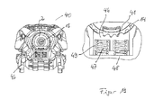
- the FIG. 17 1 shows the toe holder 40 with the inserted adjustment device 1.
- the adjustment device 1 comprises a mounting device 42 which at least partially surrounds the adjustment member 2 and / or the coupling member 3 for installation in the toe holder 40.
- the installation device 42 comprises a body 43 with a through-opening 44 and an outer shape, which is adapted to the toe holder 40, in which it is to be installed.
- the installation device 42 has a window 45, through which at least one value of the scale 10 can be read off.
- the installation device has a front section 42b1, which is located in the direction of skiing, which forms a downwardly open receiving space and a second, which adjoins the first section 42b1 in the ski direction subsequent section 42b2, in the form of an at least partially open groove.
- the receiving space receives the counter-engagement 46, which can be biased by at least one spring element 47 in the direction of the passage opening 44.
- the counter-engagement 46 is part-circularly formed on its side facing the cap 14 and has counter-engagement elements which can engage with the teeth 41 of the cap to secure the cap 14 in a set rotational position. In the groove engages a fixing element 39, which prevents the coupling member 3 can rotate in the mounting device 42 relative to the adjusting member 2.
- FIG. 18 shows in a section along a direction substantially parallel to the ski longitudinal axis through the toe holder 40, the installation situation of the setting device 1.
- the toe holder 40 comprises a bottom 48 which in the embodiment with the Mounting device 42 is connected by screws.
- the bottom 48 together with the mounting device 42, a chamber 49 in which the spring elements 47 and the counter-engagement 46 are held and guided.
- the counter-engagement 46 is engaged with the teeth 41 of the cap 14 of the adjustment member 2.
- the teeth 41 against the Federkaft the spring elements 47 displace the counter-engagement 46 down into the chamber 49.
- the spring elements 47 of the counter-engagement 46 is always pressed back to its original position, so that the teeth of the counter-engagement 46 and the cap 14 engage and secure the cap 14 in the set position against unintentional rotation by forces acting on the ski forces.
- FIG. 19 shows yet in another view the counter-engagement 46 in engagement with the teeth 41 of the cap 14.
- the counter-engagement 46 is pressed by the spring elements 47 against the cap 14 and the teeth 41 are engaged with the counter-engagement elements 46a in engagement.
- the spring elements 47 and the counter-engagement 46 are guided and supported in the chamber 49, wherein the chamber 49 is formed by the first portion 42 b 1 of the bottom 42 b of the installation device 42 and the bottom 48.
Landscapes
- Footwear And Its Accessory, Manufacturing Method And Apparatuses (AREA)
Applications Claiming Priority (1)
| Application Number | Priority Date | Filing Date | Title |
|---|---|---|---|
| DE102014104612.9A DE102014104612A1 (de) | 2014-04-01 | 2014-04-01 | Einstellschraube |
Publications (2)
| Publication Number | Publication Date |
|---|---|
| EP2926876A1 true EP2926876A1 (fr) | 2015-10-07 |
| EP2926876B1 EP2926876B1 (fr) | 2017-03-22 |
Family
ID=52736970
Family Applications (1)
| Application Number | Title | Priority Date | Filing Date |
|---|---|---|---|
| EP15161145.6A Active EP2926876B1 (fr) | 2014-04-01 | 2015-03-26 | Vis de réglage avec rainure de came circulaire |
Country Status (2)
| Country | Link |
|---|---|
| EP (1) | EP2926876B1 (fr) |
| DE (1) | DE102014104612A1 (fr) |
Families Citing this family (1)
| Publication number | Priority date | Publication date | Assignee | Title |
|---|---|---|---|---|
| US10105587B2 (en) * | 2012-04-12 | 2018-10-23 | William L. Cyr | Free heel touring-style ski binding slip differential cassette |
Citations (5)
| Publication number | Priority date | Publication date | Assignee | Title |
|---|---|---|---|---|
| CH428522A (de) * | 1963-04-30 | 1967-01-15 | Smolka & Co Wiener Metall | Federverrastung, insbesondere für Skibindungen |
| CH530566A (de) * | 1970-02-03 | 1972-11-15 | Smolka & Co Wiener Metall | Vorrichtung zur federnden Verrastung zweier Bauteile gegeneinander, insbesondere für Sicherheitsskibindungen |
| US3866929A (en) * | 1972-08-21 | 1975-02-18 | Daniel Lacroix | Ski binding |
| FR2299053A1 (fr) * | 1975-01-28 | 1976-08-27 | Beyl Jean Joseph Alfred | Fixation de securite pour ski comportant une plaque destinee a recevoir la chaussure correspondan |
| JPS5394769U (fr) * | 1970-02-03 | 1978-08-02 |
-
2014
- 2014-04-01 DE DE102014104612.9A patent/DE102014104612A1/de not_active Withdrawn
-
2015
- 2015-03-26 EP EP15161145.6A patent/EP2926876B1/fr active Active
Patent Citations (5)
| Publication number | Priority date | Publication date | Assignee | Title |
|---|---|---|---|---|
| CH428522A (de) * | 1963-04-30 | 1967-01-15 | Smolka & Co Wiener Metall | Federverrastung, insbesondere für Skibindungen |
| CH530566A (de) * | 1970-02-03 | 1972-11-15 | Smolka & Co Wiener Metall | Vorrichtung zur federnden Verrastung zweier Bauteile gegeneinander, insbesondere für Sicherheitsskibindungen |
| JPS5394769U (fr) * | 1970-02-03 | 1978-08-02 | ||
| US3866929A (en) * | 1972-08-21 | 1975-02-18 | Daniel Lacroix | Ski binding |
| FR2299053A1 (fr) * | 1975-01-28 | 1976-08-27 | Beyl Jean Joseph Alfred | Fixation de securite pour ski comportant une plaque destinee a recevoir la chaussure correspondan |
Also Published As
| Publication number | Publication date |
|---|---|
| DE102014104612A1 (de) | 2015-10-01 |
| EP2926876B1 (fr) | 2017-03-22 |
Similar Documents
| Publication | Publication Date | Title |
|---|---|---|
| DE2237580C3 (de) | Auszieh- und Eindrückvorrichtung zur leicht lösbaren Befestigung eines Geräte-Einschubteils in einen Rahmen | |
| WO2008131466A1 (fr) | Tampon amortisseur pour meuble | |
| DE20202929U1 (de) | Elektrischer Schalter mit einer Antriebswelle und mit einem Sperrmechanismus zum Sperren des Betätigens | |
| DE202006009889U1 (de) | Hantel mit verstellbarem Gewicht | |
| DE102008021002A1 (de) | Schlosseinsatz für ein Glastürschloss | |
| EP2281482B1 (fr) | Dispositifs d'éjection d'un guidage d'extraction et guidage d'extraction | |
| DE4024614C2 (de) | Fenster- oder Türbeschlag | |
| DE8900755U1 (de) | Sicherung einer Schraube | |
| DE19528901A1 (de) | Höhenverstellbarer Fuß für Küchengeräte oder Möbel | |
| EP2926876B1 (fr) | Vis de réglage avec rainure de came circulaire | |
| EP0754827A2 (fr) | Dispositif pour la fixation amovible et axialement non coulissante d'une poignée sur un élément de palier, notamment pour une poignée de porte ou fenêtre | |
| DE102018100360A1 (de) | Rosettengarnitur | |
| DE602004013095T2 (de) | Snowboardbindung | |
| DE10037550A1 (de) | Kabelanschlussvorrichtung | |
| DE202016003562U1 (de) | Anordnung mit einer Aktions-Spiralfeder zur Erzeugung einer Kraft und mit einem Rastmechanismus zum Auslösen der gespannten und zum Spannen der entspannten Aktions-Spiralfeder | |
| DE4016285C2 (fr) | ||
| DE29603389U1 (de) | Schnellverschluß | |
| EP3369946A1 (fr) | Cheville plate et procédé de montage d'une cheville plate dans une paroi | |
| DE102010000162B4 (de) | Werkzeugkopfpositionierstruktur für einen flexiblen Schraubenschlüssel | |
| EP2923741B1 (fr) | Liaison détachable dotée d'un levier de fixation et de libération d'un support de chaussure | |
| DE202007017951U1 (de) | Gehäuse mit einer darin angeordneten Baugruppe | |
| EP1457137A1 (fr) | Accouplement pour tiroirs coulissants de meubles | |
| DE202012010979U1 (de) | Schubstangenverschluss | |
| DE102014104126A1 (de) | Drehbare und arretierbare Ablageeinrichtung für einen Gegenstand | |
| DE102014102912A1 (de) | Kompostgabel |
Legal Events
| Date | Code | Title | Description |
|---|---|---|---|
| PUAI | Public reference made under article 153(3) epc to a published international application that has entered the european phase |
Free format text: ORIGINAL CODE: 0009012 |
|
| AK | Designated contracting states |
Kind code of ref document: A1 Designated state(s): AL AT BE BG CH CY CZ DE DK EE ES FI FR GB GR HR HU IE IS IT LI LT LU LV MC MK MT NL NO PL PT RO RS SE SI SK SM TR |
|
| AX | Request for extension of the european patent |
Extension state: BA ME |
|
| 17P | Request for examination filed |
Effective date: 20151112 |
|
| RBV | Designated contracting states (corrected) |
Designated state(s): AL AT BE BG CH CY CZ DE DK EE ES FI FR GB GR HR HU IE IS IT LI LT LU LV MC MK MT NL NO PL PT RO RS SE SI SK SM TR |
|
| GRAP | Despatch of communication of intention to grant a patent |
Free format text: ORIGINAL CODE: EPIDOSNIGR1 |
|
| INTG | Intention to grant announced |
Effective date: 20161031 |
|
| GRAS | Grant fee paid |
Free format text: ORIGINAL CODE: EPIDOSNIGR3 |
|
| GRAA | (expected) grant |
Free format text: ORIGINAL CODE: 0009210 |
|
| AK | Designated contracting states |
Kind code of ref document: B1 Designated state(s): AL AT BE BG CH CY CZ DE DK EE ES FI FR GB GR HR HU IE IS IT LI LT LU LV MC MK MT NL NO PL PT RO RS SE SI SK SM TR |
|
| REG | Reference to a national code |
Ref country code: GB Ref legal event code: FG4D Free format text: NOT ENGLISH |
|
| REG | Reference to a national code |
Ref country code: CH Ref legal event code: EP Ref country code: CH Ref legal event code: NV Representative=s name: RIEDERER HASLER AND PARTNER PATENTANWAELTE AG, CH |
|
| REG | Reference to a national code |
Ref country code: AT Ref legal event code: REF Ref document number: 877143 Country of ref document: AT Kind code of ref document: T Effective date: 20170415 |
|
| REG | Reference to a national code |
Ref country code: IE Ref legal event code: FG4D Free format text: LANGUAGE OF EP DOCUMENT: GERMAN |
|
| REG | Reference to a national code |
Ref country code: DE Ref legal event code: R096 Ref document number: 502015000728 Country of ref document: DE |
|
| REG | Reference to a national code |
Ref country code: NL Ref legal event code: MP Effective date: 20170322 |
|
| PG25 | Lapsed in a contracting state [announced via postgrant information from national office to epo] |
Ref country code: HR Free format text: LAPSE BECAUSE OF FAILURE TO SUBMIT A TRANSLATION OF THE DESCRIPTION OR TO PAY THE FEE WITHIN THE PRESCRIBED TIME-LIMIT Effective date: 20170322 Ref country code: FI Free format text: LAPSE BECAUSE OF FAILURE TO SUBMIT A TRANSLATION OF THE DESCRIPTION OR TO PAY THE FEE WITHIN THE PRESCRIBED TIME-LIMIT Effective date: 20170322 Ref country code: LT Free format text: LAPSE BECAUSE OF FAILURE TO SUBMIT A TRANSLATION OF THE DESCRIPTION OR TO PAY THE FEE WITHIN THE PRESCRIBED TIME-LIMIT Effective date: 20170322 Ref country code: NO Free format text: LAPSE BECAUSE OF FAILURE TO SUBMIT A TRANSLATION OF THE DESCRIPTION OR TO PAY THE FEE WITHIN THE PRESCRIBED TIME-LIMIT Effective date: 20170622 Ref country code: GR Free format text: LAPSE BECAUSE OF FAILURE TO SUBMIT A TRANSLATION OF THE DESCRIPTION OR TO PAY THE FEE WITHIN THE PRESCRIBED TIME-LIMIT Effective date: 20170623 |
|
| REG | Reference to a national code |
Ref country code: LT Ref legal event code: MG4D |
|
| PG25 | Lapsed in a contracting state [announced via postgrant information from national office to epo] |
Ref country code: LV Free format text: LAPSE BECAUSE OF FAILURE TO SUBMIT A TRANSLATION OF THE DESCRIPTION OR TO PAY THE FEE WITHIN THE PRESCRIBED TIME-LIMIT Effective date: 20170322 Ref country code: BG Free format text: LAPSE BECAUSE OF FAILURE TO SUBMIT A TRANSLATION OF THE DESCRIPTION OR TO PAY THE FEE WITHIN THE PRESCRIBED TIME-LIMIT Effective date: 20170622 Ref country code: RS Free format text: LAPSE BECAUSE OF FAILURE TO SUBMIT A TRANSLATION OF THE DESCRIPTION OR TO PAY THE FEE WITHIN THE PRESCRIBED TIME-LIMIT Effective date: 20170322 Ref country code: SE Free format text: LAPSE BECAUSE OF FAILURE TO SUBMIT A TRANSLATION OF THE DESCRIPTION OR TO PAY THE FEE WITHIN THE PRESCRIBED TIME-LIMIT Effective date: 20170322 |
|
| PG25 | Lapsed in a contracting state [announced via postgrant information from national office to epo] |
Ref country code: NL Free format text: LAPSE BECAUSE OF FAILURE TO SUBMIT A TRANSLATION OF THE DESCRIPTION OR TO PAY THE FEE WITHIN THE PRESCRIBED TIME-LIMIT Effective date: 20170322 |
|
| PG25 | Lapsed in a contracting state [announced via postgrant information from national office to epo] |
Ref country code: SK Free format text: LAPSE BECAUSE OF FAILURE TO SUBMIT A TRANSLATION OF THE DESCRIPTION OR TO PAY THE FEE WITHIN THE PRESCRIBED TIME-LIMIT Effective date: 20170322 Ref country code: IT Free format text: LAPSE BECAUSE OF FAILURE TO SUBMIT A TRANSLATION OF THE DESCRIPTION OR TO PAY THE FEE WITHIN THE PRESCRIBED TIME-LIMIT Effective date: 20170322 Ref country code: RO Free format text: LAPSE BECAUSE OF FAILURE TO SUBMIT A TRANSLATION OF THE DESCRIPTION OR TO PAY THE FEE WITHIN THE PRESCRIBED TIME-LIMIT Effective date: 20170322 Ref country code: EE Free format text: LAPSE BECAUSE OF FAILURE TO SUBMIT A TRANSLATION OF THE DESCRIPTION OR TO PAY THE FEE WITHIN THE PRESCRIBED TIME-LIMIT Effective date: 20170322 Ref country code: CZ Free format text: LAPSE BECAUSE OF FAILURE TO SUBMIT A TRANSLATION OF THE DESCRIPTION OR TO PAY THE FEE WITHIN THE PRESCRIBED TIME-LIMIT Effective date: 20170322 Ref country code: ES Free format text: LAPSE BECAUSE OF FAILURE TO SUBMIT A TRANSLATION OF THE DESCRIPTION OR TO PAY THE FEE WITHIN THE PRESCRIBED TIME-LIMIT Effective date: 20170322 |
|
| PG25 | Lapsed in a contracting state [announced via postgrant information from national office to epo] |
Ref country code: PL Free format text: LAPSE BECAUSE OF FAILURE TO SUBMIT A TRANSLATION OF THE DESCRIPTION OR TO PAY THE FEE WITHIN THE PRESCRIBED TIME-LIMIT Effective date: 20170322 Ref country code: PT Free format text: LAPSE BECAUSE OF FAILURE TO SUBMIT A TRANSLATION OF THE DESCRIPTION OR TO PAY THE FEE WITHIN THE PRESCRIBED TIME-LIMIT Effective date: 20170724 Ref country code: IS Free format text: LAPSE BECAUSE OF FAILURE TO SUBMIT A TRANSLATION OF THE DESCRIPTION OR TO PAY THE FEE WITHIN THE PRESCRIBED TIME-LIMIT Effective date: 20170722 Ref country code: SM Free format text: LAPSE BECAUSE OF FAILURE TO SUBMIT A TRANSLATION OF THE DESCRIPTION OR TO PAY THE FEE WITHIN THE PRESCRIBED TIME-LIMIT Effective date: 20170322 |
|
| REG | Reference to a national code |
Ref country code: IE Ref legal event code: MM4A |
|
| REG | Reference to a national code |
Ref country code: DE Ref legal event code: R097 Ref document number: 502015000728 Country of ref document: DE |
|
| PLBE | No opposition filed within time limit |
Free format text: ORIGINAL CODE: 0009261 |
|
| REG | Reference to a national code |
Ref country code: FR Ref legal event code: ST Effective date: 20171227 |
|
| STAA | Information on the status of an ep patent application or granted ep patent |
Free format text: STATUS: NO OPPOSITION FILED WITHIN TIME LIMIT |
|
| PG25 | Lapsed in a contracting state [announced via postgrant information from national office to epo] |
Ref country code: MC Free format text: LAPSE BECAUSE OF FAILURE TO SUBMIT A TRANSLATION OF THE DESCRIPTION OR TO PAY THE FEE WITHIN THE PRESCRIBED TIME-LIMIT Effective date: 20170322 Ref country code: DK Free format text: LAPSE BECAUSE OF FAILURE TO SUBMIT A TRANSLATION OF THE DESCRIPTION OR TO PAY THE FEE WITHIN THE PRESCRIBED TIME-LIMIT Effective date: 20170322 Ref country code: LU Free format text: LAPSE BECAUSE OF NON-PAYMENT OF DUE FEES Effective date: 20170326 Ref country code: FR Free format text: LAPSE BECAUSE OF NON-PAYMENT OF DUE FEES Effective date: 20170522 |
|
| 26N | No opposition filed |
Effective date: 20180102 |
|
| PG25 | Lapsed in a contracting state [announced via postgrant information from national office to epo] |
Ref country code: IE Free format text: LAPSE BECAUSE OF NON-PAYMENT OF DUE FEES Effective date: 20170326 Ref country code: SI Free format text: LAPSE BECAUSE OF FAILURE TO SUBMIT A TRANSLATION OF THE DESCRIPTION OR TO PAY THE FEE WITHIN THE PRESCRIBED TIME-LIMIT Effective date: 20170322 |
|
| REG | Reference to a national code |
Ref country code: BE Ref legal event code: MM Effective date: 20170331 |
|
| PG25 | Lapsed in a contracting state [announced via postgrant information from national office to epo] |
Ref country code: BE Free format text: LAPSE BECAUSE OF NON-PAYMENT OF DUE FEES Effective date: 20170331 |
|
| PG25 | Lapsed in a contracting state [announced via postgrant information from national office to epo] |
Ref country code: MT Free format text: LAPSE BECAUSE OF FAILURE TO SUBMIT A TRANSLATION OF THE DESCRIPTION OR TO PAY THE FEE WITHIN THE PRESCRIBED TIME-LIMIT Effective date: 20170322 |
|
| PG25 | Lapsed in a contracting state [announced via postgrant information from national office to epo] |
Ref country code: HU Free format text: LAPSE BECAUSE OF FAILURE TO SUBMIT A TRANSLATION OF THE DESCRIPTION OR TO PAY THE FEE WITHIN THE PRESCRIBED TIME-LIMIT; INVALID AB INITIO Effective date: 20150326 |
|
| PG25 | Lapsed in a contracting state [announced via postgrant information from national office to epo] |
Ref country code: CY Free format text: LAPSE BECAUSE OF FAILURE TO SUBMIT A TRANSLATION OF THE DESCRIPTION OR TO PAY THE FEE WITHIN THE PRESCRIBED TIME-LIMIT Effective date: 20170322 |
|
| GBPC | Gb: european patent ceased through non-payment of renewal fee |
Effective date: 20190326 |
|
| PG25 | Lapsed in a contracting state [announced via postgrant information from national office to epo] |
Ref country code: MK Free format text: LAPSE BECAUSE OF FAILURE TO SUBMIT A TRANSLATION OF THE DESCRIPTION OR TO PAY THE FEE WITHIN THE PRESCRIBED TIME-LIMIT Effective date: 20170322 |
|
| PG25 | Lapsed in a contracting state [announced via postgrant information from national office to epo] |
Ref country code: GB Free format text: LAPSE BECAUSE OF NON-PAYMENT OF DUE FEES Effective date: 20190326 |
|
| PG25 | Lapsed in a contracting state [announced via postgrant information from national office to epo] |
Ref country code: TR Free format text: LAPSE BECAUSE OF FAILURE TO SUBMIT A TRANSLATION OF THE DESCRIPTION OR TO PAY THE FEE WITHIN THE PRESCRIBED TIME-LIMIT Effective date: 20170322 |
|
| PGFP | Annual fee paid to national office [announced via postgrant information from national office to epo] |
Ref country code: CH Payment date: 20200320 Year of fee payment: 6 |
|
| PG25 | Lapsed in a contracting state [announced via postgrant information from national office to epo] |
Ref country code: AL Free format text: LAPSE BECAUSE OF FAILURE TO SUBMIT A TRANSLATION OF THE DESCRIPTION OR TO PAY THE FEE WITHIN THE PRESCRIBED TIME-LIMIT Effective date: 20170322 |
|
| PGFP | Annual fee paid to national office [announced via postgrant information from national office to epo] |
Ref country code: DE Payment date: 20210325 Year of fee payment: 7 |
|
| REG | Reference to a national code |
Ref country code: CH Ref legal event code: PL |
|
| PG25 | Lapsed in a contracting state [announced via postgrant information from national office to epo] |
Ref country code: CH Free format text: LAPSE BECAUSE OF NON-PAYMENT OF DUE FEES Effective date: 20210331 Ref country code: LI Free format text: LAPSE BECAUSE OF NON-PAYMENT OF DUE FEES Effective date: 20210331 |
|
| REG | Reference to a national code |
Ref country code: DE Ref legal event code: R119 Ref document number: 502015000728 Country of ref document: DE |
|
| PG25 | Lapsed in a contracting state [announced via postgrant information from national office to epo] |
Ref country code: DE Free format text: LAPSE BECAUSE OF NON-PAYMENT OF DUE FEES Effective date: 20221001 |
|
| P01 | Opt-out of the competence of the unified patent court (upc) registered |
Effective date: 20230515 |
|
| PGFP | Annual fee paid to national office [announced via postgrant information from national office to epo] |
Ref country code: AT Payment date: 20260319 Year of fee payment: 12 |