EP2927067B2 - Frein à ressort d'accumulateur électrique - Google Patents
Frein à ressort d'accumulateur électrique Download PDFInfo
- Publication number
- EP2927067B2 EP2927067B2 EP15000276.4A EP15000276A EP2927067B2 EP 2927067 B2 EP2927067 B2 EP 2927067B2 EP 15000276 A EP15000276 A EP 15000276A EP 2927067 B2 EP2927067 B2 EP 2927067B2
- Authority
- EP
- European Patent Office
- Prior art keywords
- valve
- compressed air
- valve device
- control
- holding brake
- Prior art date
- Legal status (The legal status is an assumption and is not a legal conclusion. Google has not performed a legal analysis and makes no representation as to the accuracy of the status listed.)
- Active
Links
Images

Classifications
-
- B—PERFORMING OPERATIONS; TRANSPORTING
- B60—VEHICLES IN GENERAL
- B60T—VEHICLE BRAKE CONTROL SYSTEMS OR PARTS THEREOF; BRAKE CONTROL SYSTEMS OR PARTS THEREOF, IN GENERAL; ARRANGEMENT OF BRAKING ELEMENTS ON VEHICLES IN GENERAL; PORTABLE DEVICES FOR PREVENTING UNWANTED MOVEMENT OF VEHICLES; VEHICLE MODIFICATIONS TO FACILITATE COOLING OF BRAKES
- B60T13/00—Transmitting braking action from initiating means to ultimate brake actuator with power assistance or drive; Brake systems incorporating such transmitting means, e.g. air-pressure brake systems
- B60T13/10—Transmitting braking action from initiating means to ultimate brake actuator with power assistance or drive; Brake systems incorporating such transmitting means, e.g. air-pressure brake systems with fluid assistance, drive, or release
- B60T13/66—Electrical control in fluid-pressure brake systems
- B60T13/68—Electrical control in fluid-pressure brake systems by electrically-controlled valves
- B60T13/683—Electrical control in fluid-pressure brake systems by electrically-controlled valves in pneumatic systems or parts thereof
-
- B—PERFORMING OPERATIONS; TRANSPORTING
- B60—VEHICLES IN GENERAL
- B60T—VEHICLE BRAKE CONTROL SYSTEMS OR PARTS THEREOF; BRAKE CONTROL SYSTEMS OR PARTS THEREOF, IN GENERAL; ARRANGEMENT OF BRAKING ELEMENTS ON VEHICLES IN GENERAL; PORTABLE DEVICES FOR PREVENTING UNWANTED MOVEMENT OF VEHICLES; VEHICLE MODIFICATIONS TO FACILITATE COOLING OF BRAKES
- B60T17/00—Component parts, details, or accessories of power brake systems not covered by groups B60T8/00, B60T13/00 or B60T15/00, or presenting other characteristic features
- B60T17/08—Brake cylinders other than ultimate actuators
- B60T17/083—Combination of service brake actuators with spring loaded brake actuators
Definitions
- the invention relates to an electric parking brake device for a vehicle, preferably for a commercial vehicle.
- Parking brake systems also referred to below as parking brake systems, usually include spring-loaded brake cylinders, which brake the vehicle in their vented state, while the parking brake can be released by venting the spring-loaded brake cylinder.
- a battery disconnect switch also referred to below as an emergency stop disconnect switch.
- a battery disconnect switch With such a battery disconnect switch, one or more batteries, e.g. B. in case of danger, be separated from the connected vehicle electrical system.
- the problem here is that after the emergency stop disconnector has been actuated or in general if the power supply fails, it is no longer possible to actuate an electric parking brake.
- the invention is based in particular on the object of further developing an electric parking brake in such a way that the commercial vehicle or the train combination can be safely parked or kept safely at a standstill even if the power supply fails.
- the at least one spring brake cylinder is connected to a compressed air source, e.g. B. a compressed air supply, connectable.
- the at least one spring-loaded brake cylinder is acted upon by pressure from the compressed air source via the parking brake valve arrangement in the released state of the parking brake device and can be connected to a pressure sink via the parking brake valve arrangement in the engaged state of the parking brake device.
- the pressure sink can be formed by a connection to the ambient air.
- the parking brake valve assembly is also designed to be electro-pneumatically controlled to engage the released or engaged state in a first mode of operation.
- the document DE 10 2007 051 151 A1 discloses an electropneumatic parking brake device.
- From the disclosure document DE 10 2011 016 740 A1 discloses an electropneumatic parking brake device of a towing vehicle-trailer combination for performing at least one parking brake function of a parking brake, with a valve that can be actuated by an operator being provided, which can be used to apply the trailer brake in the event of a fault in the electrical system.
- the parking brake valve arrangement has an operating unit that can be actuated by muscle power, also referred to below as the second operating element, and is also designed to be controlled purely pneumatically to engage the released or engaged state in a second operating mode using the operating unit that can be actuated by muscle power.
- the control unit that can be actuated by muscle power can be a handbrake valve, a switch, a button or a push button, etc., by means of which a compressed air line can be opened to the environment manually.
- a particular advantage of the invention is that the parking brake can be actuated independently of the electrical operating state of the vehicle.
- the parking brake valve arrangement comprises an electropneumatically controllable valve device which has connections for electrical control lines, a first connection for a supply line for connecting the valve device to the compressed air source and at least a second connection for a compressed air line for connecting the electropneumatic valve device to one or more spring brake cylinders.
- valve device is designed to apply the pressure of the compressed air source to a compressed air line connected to the at least second connection in the released state of the parking brake device and to vent the compressed air line connected to the at least one second connection in order to engage the parking brake device.
- the electropneumatically controllable valve device can have a third connection for connecting the electropneumatic valve device to a trailer valve device that controls the trailer brake system.
- the valve device can in turn be designed to apply pressure from the compressed air source to a compressed air line connected to the at least one third connection in the released state of the parking brake device and to vent the compressed air line connected to the at least one third connection in order to engage the trailer brake system.
- the aforementioned electro-pneumatically controllable valve device is provided in a structural unit, so that the electro-pneumatically controllable valve arrangement is accommodated in a housing in a structurally compact manner.
- the present invention develops such an electropneumatically controllable valve device in such a way that a switchable first control valve is also provided which has a first input pneumatically connected to the at least one second connection of the electropneumatically controllable valve device, a second input pneumatically connected to the compressed air source Has an input and an output.
- a relay valve that is external to the electropneumatic valve device, which has a control input that is pneumatically connected to the output of the first control valve, a working input that is pneumatically connected to the compressed air source, and a working output that is pneumatically connected to the at least one spring-loaded brake cylinder.
- the control element that can be actuated by muscle power is arranged between the second input of the first control valve and the compressed air source, d. H. on a compressed air line connecting the second input of the first control valve and the compressed air source.
- the control element that can be actuated by muscle power can be brought into a position in which the compressed air line is vented.
- the aforementioned relay valve is not the “internal" relay valve of the electropneumatically controllable valve device, but rather a further relay valve, also referred to below as the external relay valve.
- the known electropneumatic valve devices already have an internal relay valve via which the compressed air line or compressed air lines connected to the second connection or the second connections and the third connection of the electropneumatic valve device can be vented.
- the electric parking brake device can have a switchable second control valve.
- the second control valve has a first input that is pneumatically connected to the third port of the valve device.
- a second input of the second control valve is pneumatically connected to the compressed air line that is connected to the second input of the first control valve and can be vented by means of the control element that can be actuated by muscle power.
- An output of the second control valve is pneumatically connected to the trailer valve assembly.
- first control valve and/or the second control valve is a 3/2-way valve.
- first control valve and/or the second control valve can be designed in such a way that the control valve pneumatically connects that one of its two inputs to the output which is subjected to the lower pressure.
- the external relay valve of the aforementioned design variants can be designed in such a way that if the pressure applied to the control input falls below a predetermined minimum level, the relay valve switches from an open position, in which the working input is pneumatically connected to the working output, to a venting position, in which the working output is pneumatically connected to a venting output of the relay valve.
- the parking brake valve arrangement of the aforementioned embodiments thus includes the electropneumatically controllable valve device, the switchable first control valve, the external relay valve, and only according to the additional variant for controlling the trailer brake system, the additional switchable second control valve, which can be coupled to one another via compressed air lines, as described above.
- the parking brake valve arrangement can be controlled electro-pneumatically in a first mode of operation and purely pneumatically in a second mode of operation.
- the compressed air lines and the spring-loaded brake cylinders are pressurized or pressurized by the compressed air source.
- venting of the spring brake cylinders can be initiated electropneumatically by actuating a first control unit in the driver's cab, which is connected to the electropneumatic valve device via electrical control lines.
- the valve device is designed to vent the compressed air line connected to the second output of the valve device when a corresponding electrical control signal is received from the first operating unit.
- the first input of the first control valve arranged at the end of the vented compressed air line is subjected to a lower pressure than the second input of the first control valve, so that the first input of the first control valve is pneumatically connected to the output of the first control valve.
- the compressed air line which connects the output of the switchable first control valve to the control input of the relay valve, is also vented.
- the venting of the compressed air line connected to the output of the first control valve thus causes a pressure drop at the control input of the external relay valve, so that it switches from an open position to a venting position in which the working output of the external relay valve is pneumatically connected to a venting output of the external relay valve.
- the compressed air line connected to the work outlet which is also connected to the at least one spring cylinder, also vented to the atmosphere.
- the spring-loaded brake cylinders are also vented and the spring-loaded brakes are applied.
- the trailer valve device can be pressurized and vented directly via the electropneumatic valve device in the first operating mode in a conventional manner.
- the second control valve is switched to an open position, which connects the first input to the output of the second control valve as long as the compressed air line connected to the second input of the second control valve is not vented by means of the control element that can be actuated by muscle power.
- the third connection of the electropneumatic valve device is pneumatically connected to the trailer valve device via the first input and the output of the switchable second control valve and can thus be electropneumatically aerated and vented directly via the valve device in a known manner.
- the spring-loaded brakes can also be applied purely pneumatically according to the second operating mode.
- the second control element that can be actuated by muscle power is manually brought into an open position, so that the compressed air line is vented at the second control element.
- the pressure at the second input of the switchable first control valve drops, which activates it and pneumatically couples the second input to the output. Consequently, in turn, the compressed air line connected to the output is vented, which serves as a control line for the external relay valve, whereby, as described above, the venting of the spring-actuated brake cylinders is initiated via the venting outlet of the external relay valve.
- the trailer valve device can also be controlled purely pneumatically in the second operating mode.
- the second control element which can be actuated by muscle power, is in turn manually brought into the open position, so that the compressed air line is vented at the second control element.
- the pressure at the second input of the switchable first control valve and at the second input of the switchable second control valve drops, as a result of which they are activated.
- the second input is pneumatically coupled to the output of the second control valve. Consequently, the compressed air line connected to the outlet of the second control valve, which connects the second control valve to the trailer valve device, is in turn vented.
- the trailer valve device is vented via the second control valve and the compressed air line vented by the second control element that can be actuated by muscle power.
- Another advantage of the aforementioned embodiment is that the described expansion of a conventional electropneumatic valve device with the switchable control valve and the relay valve allows a pneumatic backup solution in a structurally simple manner, based on conventional electropneumatic parking brake valve arrangements. Another advantage is that with this approach, commercial vehicles with a conventional electric parking brake can also be retrofitted with a pneumatic backup solution with comparatively little design effort.
- the known electropneumatically controllable valve device can also be further developed only by means of the external relay valve and without a first and without a second control valve, in order to enable the second purely pneumatic operating mode.
- the pneumatic backup solution can be implemented at reduced cost.
- At least one compressed air supply line which pneumatically connects the at least one second connection of the valve device to the at least one spring brake cylinder
- a relay valve is provided which is external to the electropneumatic valve device and has a control input, a working input connected to the compressed air source and a working output pneumatically connected to the at least one spring-loaded brake cylinder.
- a control compressed air line is provided, which can be vented with the muscle-power-actuable operating element and which is connected to the control input of the relay valve and to the compressed air source, preferably via the supply line of the compressed air source.
- the working output of the external relay valve is pneumatically connected to the at least one spring brake cylinder via a compressed air line, wherein the compressed air line can open into a pressure chamber or into the compressed air supply line of the at least one spring brake cylinder.
- the spring brake cylinders are aerated and vented in the first operating mode in a conventional manner directly via the electropneumatic valve device.
- the second connections of the electropneumatic valve device are pneumatically coupled directly to the pressure chambers of the spring-loaded brake cylinders via compressed air lines, so that the pressure of the pressure reservoir is applied to the second outlet for ventilation and the second connection is connected to a pressure sink via the electropneumatic valve device for ventilation.
- e.g. B. is connected to the ambient air.
- venting of the control input of the relay valve is initiated by actuating the second control element that can be actuated by muscle power, so that the relay valve switches to the venting position.
- the spring-loaded brake cylinders are activated via the compressed air line, which pneumatically connects the working output of the relay valve to the spring-loaded brake cylinders.
- a compressed air supply line can also be provided, which pneumatically connects the third connection of the electropneumatic valve device to the trailer valve device.
- the variant provides that a control compressed air line is provided, which can be vented with the muscle-power-actuable control element and which is connected to a control input of a relay valve of the valve device and to the supply line of the compressed air source.
- This embodiment variant thus utilizes the fact that known electropneumatic valve devices already have an internal relay valve via which the compressed air line or compressed air lines connected to the second connection or the second connections of the electropneumatic valve device can be vented.
- the electropneumatic valve device is provided with a further connection, via which the compressed air control line can be pneumatically connected to the control input of the internal relay valve of the valve device.
- At least one compressed air supply line is also provided, which pneumatically connects the at least one second connection of the valve device to the at least one spring brake cylinder.
- the electropneumatic valve device can thus be connected directly to the spring-loaded brake cylinders via its second connections, as would also be the case with a conventional electric spring-loaded parking brake device without a pneumatic backup solution.
- the internal relay valve of the electropneumatic valve device can be designed in such a way that if the pressure falls below a predetermined minimum pressure applied to the control input of the relay valve of the valve device, the relay valve switches from an open position to a vent position, with one on the second connection of the valve device connected compressed air line is pneumatically connected to a vent outlet of the relay valve.
- control input of the internal relay valve of the valve device is designed in such a way that it can be controlled both electrically via the electrical connections of the valve device and purely pneumatically via the additional control compressed air line, which is pneumatically connected to the control input of the relay valve.
- a venting of the compressed air control line, which is connected to the control chamber of the internal relay valve, can thus be initiated by actuating the control element that can be actuated by muscle power.
- the working chamber of the internal relay valve, which is connected directly to the spring-loaded brake cylinders via compressed air lines, is then also vented.
- a braking force is then built up on the vehicle wheels, on which the spring brake cylinders are arranged, and the vehicle comes to a standstill or is blocked.
- a compressed air line connected to the third connection of the electropneumatic controllable valve device for connection to the trailer valve device can then also be aerated and bled either electropneumatically or purely pneumatically in a manner analogous to the compressed air lines which are connected to the second connections.
- control element that can be actuated by muscle power is arranged in the driver's cab of a commercial vehicle, so that the driver can engage the parking brake without having to get out of the driver's cab even after the power supply has been interrupted. This is particularly advantageous if the vehicle is currently on an incline.
- a further aspect of the invention relates to a utility vehicle with an electric parking brake device according to one of the preceding aspects.
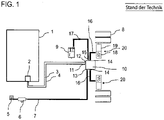
- the parking brake system controls the parking brake via a pressure medium circuit.
- the part of the pressure medium circuit shown comprises a pressure medium reservoir 6, which is pneumatically connected via a supply line 7 to a first connection 13 of an electrically controllable valve device 10, and also a first parking brake operating unit 2 arranged inside the driver's cab 1, which is electrically connected via lines 3, 4 to a Control unit (not shown) of the electropneumatic valve device 10 is connected.
- the valve device 10 is connected to the spring brake cylinders 18 via compressed air lines 16 .
- the spring-loaded brake cylinders 18 are designed as part of a combination brake cylinder 20, also known as a tristop cylinder, which is first arranged on a wheel axle of the commercial vehicle.
- the combination brake cylinder 20 comprises a diaphragm cylinder 19 for actuating the service brake and a spring-loaded brake cylinder 18 to operate the parking brake.
- the spring brake cylinder 18 has a spring chamber with a spring and a pressure chamber which can be pressurized via the compressed air lines 16 or vented.
- the spring-loaded brake cylinders 18 serve as an actuator device to actuate mechanical components of a wheel brake device of a wheel 8, in particular to bring the mechanical components into engagement (spring-loaded brake cylinder vented) and/or out of engagement (spring-loaded brake cylinder vented).
- the pressure medium circuit includes further in figure 1 Components arranged to the left of the pressure medium reservoir 6, such as a four-circuit protection valve, a compressor, a pressure regulator, etc., of which to simplify the illustration in figure 1 only the four-circuit protection valve 5 is shown.
- the electropneumatically controllable valve device 10 used for the electropneumatic control of the ventilation or venting of the spring-loaded brake cylinders 18 is known per se from the prior art and therefore does not have to be described in more detail.
- the electropneumatically controllable valve device 10 has connections 11, 12 for electrical control lines 3, 4, a first connection 13 for a supply line for connecting the valve device 10 to a compressed air supply 6 and further connections 14, 15 for compressed air lines 16 , 17 has.
- Such valve devices 10 can be implemented as a structural unit on which the corresponding connections 11 to 15 are provided in order to connect the electrical and pneumatic lines to the valve device 10 .
- the valve device 10 is designed to apply pressure from the compressed air supply 6 to a compressed air line 16 connected to the connection 14 in the released state of the parking brake device and to vent the compressed air line 16 to engage the parking brake device.
- the specific valve arrangement inside the valve device 10 which is designed in the usual way, is not shown.
- the valve arrangement inside the valve device 10 usually includes a relay valve (not shown), which can be switched into an open position (parking brake when not engaged) and a venting position (parking brake when engaged), with the venting position a working chamber of the internal relay valve, which is connected to the spring brake cylinder 18 via the compressed air line 16, is vented via a vent outlet.
- the parking brake valve device also has a connection 15 which is intended to be connected to a trailer control valve arrangement 9 .
- the valve arrangement 10 is also designed to actuate the parking brake of the utility vehicle and to pressurize the connection 15 in such a way that the brake system of a trailer connected to the trailer control valve arrangement 9 is also actuated.
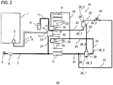
- FIG. 1 schematically illustrates a first exemplary embodiment of the present invention with a block diagram.
- components with the same reference numerals correspond to the components of figure 1 and are not described separately.
- FIG. 1 illustrated pressure medium circuit comprising the electropneumatically controllable valve device 10
- FIG. 1 illustrated pressure medium circuit comprising the electropneumatically controllable valve device 10
- FIG. 1 illustrated pressure medium circuit comprising the electropneumatically controllable valve device 10
- FIG. 1 illustrated pressure medium circuit comprising the electropneumatically controllable valve device 10
- FIG. 1 illustrated pressure medium circuit comprising the electropneumatically controllable valve device 10
- the parking brake valve device 32 also includes a 3/2-way valve 29, a relay valve 28 and a hand brake valve 30.
- the second connections 14 of the control device 10 are not directly connected to the pressure chambers of the spring brake cylinders 18 . Instead, a compressed air line 21 is attached to only one of the connections 14 and is also connected to a first input 29_1 of the 3/2-way valve 29 .
- the 3/2-way valve 29 also has a second input 29_3 connected to the compressed air source 6 and an output 29_2.
- the additional relay valve 28 is also provided, which has a control input 28_4 connected to the output 29_2 of the control valve 29, a working input 28_1 connected to the compressed air source 6 and a working output 28_2 connected to the two spring brake cylinders 18.
- a second operating element in the form of a hand brake valve 30 is arranged on the compressed air line 22 and between the second input 29_3 of the control valve 29 and the compressed air source 6 .
- the 3/2-way valve 29 serves as a switchable control valve and is designed in such a way that it pneumatically connects that one of its two inputs 29_1, 29_3 to the output 29_2 which is subjected to the lower pressure.
- the 3/2-way valve 29 can thus be operated in what is known as the “select-low operating mode”, so that the smaller of the two input pressures is always present at the output 29_2.
- the relay valve 28 is designed in such a way that when the pressure at the control input 28_4 falls below a predetermined minimum value, the relay valve 28 switches from an open position to a vent position, with the working input 28_1 being connected to the working outlet 28_2 in the open position and the working outlet 28_2 being connected to a Vent output 28_3 of the relay valve 28 is pneumatically connected.
- the handbrake valve 30 is also arranged inside the driver's cab 1, which figure 2 but is not shown. Thus, a section of the line 22 leads to the interior of the driver's cab 1, where the handbrake valve 30 is arranged. It is therefore emphasized that the presentation of figure 2 and the figure 3 is only intended to clarify the connections of the individual air pressure lines with the valve connections, but does not show the actual course of the lines in the vehicle.
- the first and second modes of operation of the electric parking brake device 40 are described below by way of example.
- the compressed air lines 7, 17, 21-27 and the spring brake cylinders 18 are ventilated, i. H. is acted upon by a pressure from the pressure reservoir device 6, so that the air pressure applied to the spring-loaded brake cylinders tensions the spring elements and thereby keeps the mechanical components of the wheel brake disengaged.
- the relay valve 28 is in the open position.
- the parking brake can be engaged in an electrically controlled manner according to the first operating mode.
- the driver can operate the first control unit 2 in the driver's cab.
- the control unit of the valve device 10 is designed in such a way that it vents the compressed air line 21 by controlling the internal valve arrangement of the valve device 10 .
- the venting takes place via an internal relay valve (not shown) of the valve device 10, which releases the compressed air during venting via a vent outlet of the internal relay valve to the environment.
- the compressed air line 21 is pneumatically coupled to the compressed air line 23 via the 3/2-way valve 29, the compressed air line 23 is also vented as a result.
- the relay valve 28 By venting the line 23, which is present at the control input 28_4 of the relay valve 28, the relay valve 28 switches from an open position, in which the working input 28_1 is in the flow position with the working output 28_2, to a venting position, in which the working output 28_2 is connected to a vent output 28_3 of the relay valve 28 is pneumatically connected.
- the second purely pneumatic operating mode is described below. If the vehicle's power supply has failed or if the battery disconnect switch (emergency off switch) has been actuated, the valve device 10 can no longer be controlled electrically. However, the parking brake can be engaged using the pneumatic backup circuit.
- the hand brake valve 30 is actuated in order to vent the compressed air line 22 .
- the venting of the compressed air line 22 causes activation of the 3/2-way valve 29. Since the venting causes the input 29_3 to have a lower pressure than the input 29_1, the 3/2-way valve 29 switches to a position in which the input 29_3 is connected to the output 29_2. Then the compressed air line 23 is also vented.
- venting the compressed air line 23 causes the relay valve 28 to switch to the venting position, so that the compressed air line 24 and thus also the compressed air line 25 are vented, which in turn leads to a venting of the spring brake cylinder 18 and to the construction of a Braking force on the relevant vehicle wheels 8 leads.
- the parking brake is deactivated by actuating the hand brake valve 30 again or by venting the aforementioned compressed air lines together with the spring brake cylinders 18.
- the aforementioned functional principle can also be expanded by installing another 3/2-way valve on the trailer control 9, which is not shown for reasons of clarity.
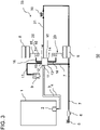
- FIG figure 3 schematically shows a further non-claimed exemplary embodiment of an electric parking brake device 50 with a parking brake valve device 33.
- components with the same reference numbers again correspond to the components of FIG figure 1 or 2 and are not described separately.
- the valve device 10 of figure 3 differs, however, from the valve device 10 of FIG figure 1 , as explained below.
- the second connections 14 and the third connection 15 are of the valve device 10 via the compressed air lines 16 or the compressed air line 17 in a conventional manner as in figure 1 pneumatically connected directly to the spring brake cylinders 18 or to the trailer valve device 9 .
- a special feature of this exemplary embodiment is that a control compressed air line 31 is also provided, which can be vented with the hand brake valve 30 and which is pneumatically connected to a control input or the control chamber of a relay valve (not shown) of the valve device 10 and to the supply line 7 of the compressed air source .
- the valve device 10 includes an internal relay valve via which the compressed air lines 16, 17 can be aerated and vented.
- the compressed air lines 7, 16, 17 and 31 and the spring-loaded brake cylinders 18 are ventilated, i. H. is acted upon by a pressure from the pressure reservoir device 6, so that the air pressure applied to the spring-loaded brake cylinders tensions the spring elements and thereby keeps the mechanical components of the wheel brake disengaged.
- the operating unit 2 in the driver's cab when the power supply is normal, the operating unit 2 in the driver's cab generates an electrical signal when it is actuated, which is transmitted to the control unit 10 via the control lines 3, 4.
- the control unit 10 When this signal is received, the control unit 10 is designed to vent the compressed air lines 16 , 17 and thus the spring-loaded brake cylinders 18 or the line 17 to the trailer valve device 9 via the connections 14 , 15 . In this case, venting takes place via the internal relay valve of the valve arrangement 10, which is switched to a venting position by the control unit of the valve device 10, so that the compressed air can be discharged to the environment.
- a venting of the compressed air line 31 can be initiated by actuating the second actuating element 30, which is also arranged in the driver's cab 2.
- the compressed air line 31 is connected to the control chamber of the internal relay valve of the control unit 10 .
- the venting of the compressed air line 31 causes the pressure in the control chamber of the internal relay valve to drop, as a result of which the working chamber of the relay valve, which is directly connected to the spring brake cylinders 18 via the compressed air lines 16, is also vented.
- a braking force is then built up at the relevant vehicle wheels and the vehicle comes to a standstill or is arrested.
- the brake system of the trailer vehicle can also be actuated in the second operating mode.
- the parking brake is deactivated by actuating the operating element 30 again or by venting the aforementioned compressed air lines together with the spring-loaded brake cylinders 18.
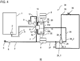
- FIG 4 shows a further exemplary embodiment of an electric parking brake device 60 with a parking brake valve device 34.
- components with the same reference numbers again correspond to the components of the previous figures and are not described separately.
- the second connections 14 of the valve device 10 are again connected via the compressed air lines 16 in a conventional manner as in FIG figure 1 or figure 3 connected directly to the spring brake cylinders 18.
- the parking brake valve device 34 also includes an external relay valve 28 which has a control input 28_4, a working input 28_1 which is pneumatically connected to the compressed air source 6 via the lines 26 and 27 and a working output 28_2 which is pneumatically connected to the two spring brake cylinders 18. Furthermore, a control compressed air line 36 is provided, which can be vented with the muscle-power-operated operating element 30 and which is connected to the control input of the relay valve 28 and to the compressed air source 6 via the compressed air lines 26, 27 and 7.
- the working outlet 28_2 of the relay valve is pneumatically connected to the two spring-loaded brake cylinders 18 via the compressed air line 35, with the compressed air line 35 branching off to the two spring-loaded brake cylinders 18 (lines 35a, 35b) and opening directly into the respective pressure chamber of the spring-loaded brake cylinders 18.
- the lines 35a, 35b can also be pneumatically connected directly to the line 16.
- the relay valve 28 is in turn designed in such a way that if the pressure at the control input 28_4 falls below a predetermined minimum level, the relay valve 28 switches from an open position to a vent position, with the working outlet 28_2 being connected pneumatically to a vent outlet 28_3 of the relay valve in the vent position connected is.
- the first operating mode is analogous to that in figure 3 shown embodiment, in which the spring brake cylinder via the lines 16 and the internal relay valve (not shown) of the valve device 10 are vented.
- venting of the compressed air line 36 is again initiated by actuating the handbrake valve 30 in order to vent the compressed air line 36 .
- This causes the pressure at the control input 28_4 to drop, so that the relay valve 28 switches to the venting position.
- the compressed air line 35 with the sections 35a, 35b and thus the spring brake cylinder 18 is vented.
- the entire supply in the compressed air supply 6 is also slowly vented, limited by the protective function of the four-circuit valve 5 for the other circuits, since the valve device 10, in particular the internal relay valve, is still switched to open.
- FIG 5 schematically shows a further exemplary embodiment of an electric parking brake device 70 with a parking brake valve device 42.
- the exemplary embodiment is a modification of that in FIG figure 2 shown embodiment, in order to be able to actuate a trailer valve device 9 and a trailer brake system (not shown) connected thereto purely pneumatically in the second operating mode.
- components with the same reference numerals correspond to the components of figure 2 and are not described separately.
- the electric parking brake device 70 also has a switchable second 3/2-way valve 41, which has a first input 41_1 connected to the connection 15 of the valve device 10, a second input 41_3, which is connected via the compressed air line 39 to the second input 29_3 of the first 3/ 2-way valve 29 is connected, and has an outlet 41_2 connected to the trailer valve device 9 .
- the second directional valve 41 is designed in such a way that it pneumatically connects that one of its two inputs 41_1, 41_3 to the output 41_2 which is subjected to the lower pressure.
- the trailer valve device or the trailer brake system is aerated and vented in a conventional manner directly via the electropneumatic valve device 10.
- the second 3/2-way valve 41 is switched to an open position. which connects the first input 41_1 to the output 41_2 of the 3/2-way valve 41 as long as the compressed air line 39 connected to the second input 41_3 is pressurized and has not been vented by means of the hand brake valve 30.
- the connection 15 of the electropneumatic valve device 10 is pneumatically connected to the trailer valve device 9 via the first input 41_1 and the output 41_2 of the switchable second control valve 41 .
- the valve device 9 can thus be aerated and vented in a known manner directly via the valve device 10 by appropriate control of its internal relay valve, not shown.
- the electric parking brake device 70 can also be actuated purely pneumatically in the second operating mode.
- the handbrake valve 30 is manually brought into the open position, so that the compressed air line 22 and thus the compressed air line 29 are vented.
- the line pressure at the second input 41_3 of the second 3/2-way valve 41 drops, which activates it and pneumatically couples the second input 41_3 to the output 41_2. Consequently, the compressed air line 38 connected to the outlet 41_2 of the second 3/2-way valve 41 is vented via the second 3/2-way valve 41 and the compressed air lines 39 and 22 .
- the spring brake cylinders are bled in the same way as in connection with figure 2 described.
Landscapes
- Engineering & Computer Science (AREA)
- Transportation (AREA)
- Mechanical Engineering (AREA)
- Braking Systems And Boosters (AREA)
- Valves And Accessory Devices For Braking Systems (AREA)
- Regulating Braking Force (AREA)
Claims (8)
- Dispositif de frein de stationnement électrique (40; 50; 60; 70) pour un véhicule, en particulier pour un véhicule utilitaire, comprenantun agencement de vannes de frein de stationnement (32; 33; 34; 42); etun cylindre de frein à ressort (18), qui peut être raccordé à une source d'air comprimé (6) par une conduite d'alimentation (7) et l'agencement de vannes de frein de stationnement (32; 33; 34; 42), qui dans l'état desserré du dispositif de frein de stationnement est soumis à la pression de la source d'air comprimé (6) par l'agencement de vannes de frein de stationnement et dans l'état serré du dispositif de frein de stationnement peut être raccordé à un puits de pression par l'agencement de vannes de frein de stationnement;dans lequel l'agencement de vannes de frein de stationnement est conçu pour être commandé de façon électropneumatique dans un premier mode de fonctionnement pour engager l'état desserré ou serré;dans lequel l'agencement de vannes de frein de stationnement comprend un élément de commande (30) actionnable par la force musculaire disposé dans la cabine de conduite (1) d'un véhicule utilitaire, et est en outre conçu pour être commandé de façon purement pneumatique pour engager l'état desserré ou serré dans un deuxième mode de fonctionnement avec utilisation de l'élément de commande (30) actionnable par la force musculaire;dans lequel l'agencement de vannes de frein de stationnement (32; 33; 34) comprend un dispositif de vanne à commande électropneumatique (10), présentant des raccords (11, 12) pour des lignes de commande électriques (3, 4), un premier raccord (13) pour une conduite d'alimentation pour le raccordement du dispositif de vanne (10) à la source de pression (6), au moins un deuxième raccord (14) pour une conduite d'air comprimé (16) pour raccorder le dispositif de vanne électropneumatique (10) à un ou plusieurs cylindre(s) de frein à ressort (18), dans lequel le dispositif de vanne (10) est conçu pour, dans l'état desserré du dispositif de frein de stationnement, soumettre à la pression de la source d'air comprimé (6) une conduite d'air comprimé (16) raccordée audit au moins un deuxième raccord (14) et pour purger la conduite d'air comprimé (16) raccordée audit au moins un deuxième raccord (14) pour serrer le dispositif de frein de stationnement, et le dispositif de vanne à commande électropneumatique (10) est fourni sous la forme d'une unité de construction;caractérisé parVariante i):i.a) une première vanne de commande commutable (29), qui présente une première entrée (29_1) raccordée audit au moins un deuxième raccord (14) du dispositif de vanne (10), une deuxième entrée (29_3) raccordée à la source d'air comprimé (6) et une sortie (29_2); eti.b) une vanne relais (28), qui est externe par rapport au dispositif de vanne électropneumatique et qui présente une entrée de commande (28_4) raccordée à la sortie (29_2) de la première vanne de commande (29), une entrée de travail (28_1) raccordée à la source d'air comprimé (6) et une sortie de travail (28_2) raccordée audit au moins un cylindre de frein à ressort (18); dans lequel l'élément de commande (30) actionnable par la force musculaire peut purger la conduite d'air comprimé (22) et il est disposé entre la deuxième entrée (29_3) de la première vanne de commande et la source d'air comprimé (6);ou Variante ii):ii.a) au moins une conduite d'air comprimé d'alimentation (16), qui relie de façon pneumatique ledit au moins un deuxième raccord (14) du dispositif de vanne (10) audit au moins un cylindre de frein à ressort (18); etii.b) une vanne relais (28), qui est externe par rapport au dispositif de vanne électropneumatique, et qui présente une entrée de commande (28_4), une entrée de travail (28_1) raccordée à la source d'air comprimé (6) et une sortie de travail (28_2) raccordée de façon pneumatique audit au moins un cylindre de frein à ressort (18); etii.c) une conduite d'air comprimé de commande (36), qui peut être purgée avec l'élément de commande (30) actionnable par la force musculaire et qui est raccordée à l'entrée de commande de la vanne relais (28) et à la source d'air comprimé (6), de préférence par la conduite d'alimentation (7) de la source d'air comprimé (6).
- Dispositif de frein de stationnement électrique (40; 50; 60; 70) selon la revendication 1, caractérisé en ce que:
le dispositif de vanne à commande électropneumatique (10) présente un troisième raccord (15) pour raccorder le dispositif de vanne à commande électropneumatique (10) à un dispositif de vanne de remorque (9), dans lequel le dispositif de vanne (10) est conçu pour, dans l'état desserré du dispositif de frein de stationnement, soumettre à la pression de la source d'air comprimé (6) une conduite d'air comprimé (17) raccordée audit au moins un troisième raccord (15) et pour purger la conduite d'air comprimé (17) raccordée audit au moins un troisième raccord (15) pour serrer le dispositif de frein de stationnement. - Dispositif de frein de stationnement électrique (70) selon la revendication 1 ou 2 selon la variante i), caractérisé par une deuxième vanne de commande commutable (41), qui présente une première entrée (41_1) raccordée au troisième raccord (15) du dispositif de vanne (10), une deuxième entrée (41_3) raccordée à la conduite d'air comprimé (22) raccordée à la deuxième entrée (29_3) de la première vanne de commande (29) et pouvant être purgée au moyen de l'élément de commande (30) actionnable par la force musculaire et une sortie (41_2) raccordée au dispositif de vanne de remorque (9).
- Dispositif de frein de stationnement électrique (40; 70) selon l'une quelconque des revendications précédentes selon la variante i), caractérisé en ce que(a) la première vanne de commande (29) et/ou la deuxième vanne de commande (41) est une vanne à 3/2 voies; et/ou(b) la première vanne de commande (29) et/ou la deuxième vanne de commande (41) est configurée de telle manière qu'elle relie de façon pneumatique à la sortie celle de ses deux entrées, qui est soumise à la plus faible pression.
- Dispositif de frein de stationnement électrique (60) selon la revendication 1 ou 2 selon la variante ii), caractérisé en ce que la sortie de travail (28_2) de la vanne relais est raccordée de façon pneumatique par la conduite d'air comprimé (35) audit au moins un cylindre de frein à ressort (18), dans lequel la conduite d'air comprimé (35) débouche dans une chambre sous pression ou dans la conduite d'air comprimé d'alimentation (16) dudit au moins un cylindre de frein à ressort (18).
- Dispositif de frein de stationnement électrique (60) selon l'une quelconque des revendications 1, 2 ou 5 selon la variante ii), caractérisé par une conduite d'air comprimé d'alimentation (17), qui relie le troisième raccord (15) du dispositif de vanne (10) au dispositif de vanne de remorque (9).
- Dispositif de frein de stationnement électrique (40; 60; 70) selon l'une quelconque des revendications 1 à 6 selon les variantes i) ou ii), caractérisé en ce que la vanne relais (28) est conçue de telle manière qu'elle commute la vanne relais (28) d'une position de passage à une position de purge en cas de descente en dessous d'une pression minimale prédéterminée, à laquelle l'entrée de commande (28_4) est soumise, dans lequel dans la position de purge la sortie de travail (28_2) est raccordée de façon pneumatique à une sortie de purge (28_3) de la vanne relais.
- Véhicule utilitaire avec un dispositif de frein de stationnement électrique (40; 50; 60; 70) selon l'une quelconque des revendications précédentes.
Applications Claiming Priority (1)
| Application Number | Priority Date | Filing Date | Title |
|---|---|---|---|
| DE102014004933.7A DE102014004933A1 (de) | 2014-04-05 | 2014-04-05 | Elektrische Federspeicher-Feststellbremse |
Publications (4)
| Publication Number | Publication Date |
|---|---|
| EP2927067A2 EP2927067A2 (fr) | 2015-10-07 |
| EP2927067A3 EP2927067A3 (fr) | 2016-01-13 |
| EP2927067B1 EP2927067B1 (fr) | 2018-01-10 |
| EP2927067B2 true EP2927067B2 (fr) | 2022-12-14 |
Family
ID=52465154
Family Applications (1)
| Application Number | Title | Priority Date | Filing Date |
|---|---|---|---|
| EP15000276.4A Active EP2927067B2 (fr) | 2014-04-05 | 2015-01-29 | Frein à ressort d'accumulateur électrique |
Country Status (5)
| Country | Link |
|---|---|
| EP (1) | EP2927067B2 (fr) |
| CN (1) | CN105035056B (fr) |
| BR (1) | BR102015003671B1 (fr) |
| DE (1) | DE102014004933A1 (fr) |
| RU (1) | RU2692514C2 (fr) |
Families Citing this family (8)
| Publication number | Priority date | Publication date | Assignee | Title |
|---|---|---|---|---|
| DE102016010460A1 (de) * | 2016-08-31 | 2018-03-01 | Wabco Gmbh | Elektronisch steuerbares pneumatisches Bremssystem in einem Nutzfahrzeug sowie Verfahren zum elektronischen Steuern eines pneumatischen Bremssystems in einem Nutzfahrzeug |
| DE102016011390A1 (de) * | 2016-09-21 | 2018-03-22 | Wabco Gmbh | Parkbrems-Ventileinrichtung zur Ansteuerung einer Federspeicher-Feststellbremse |
| DE102017009307A1 (de) * | 2017-10-07 | 2019-04-11 | Wabco Gmbh | Parkbrems-Ventileinrichtung |
| WO2020038585A1 (fr) * | 2018-08-24 | 2020-02-27 | Wabco Europe Bvba | Composants de module de commande de frein pneumatique |
| DE102018122953A1 (de) | 2018-09-19 | 2020-03-19 | Knorr-Bremse Systeme für Nutzfahrzeuge GmbH | Elektronische Parkbremseinrichtung und Verfahren zum Betrieb einer elektronischen Parkbremseinrichtung |
| DE102018127822A1 (de) * | 2018-11-07 | 2020-05-07 | Knorr-Bremse Systeme für Nutzfahrzeuge GmbH | Ventilanordnung und ein Verfahren zur Drucksteuerung |
| DE102019118896A1 (de) | 2019-07-12 | 2021-01-14 | Knorr-Bremse Systeme für Nutzfahrzeuge GmbH | Parkbremseinrichtung |
| US11820341B2 (en) * | 2020-10-01 | 2023-11-21 | Valcrum, Llc | Electrically modulated air brake |
Citations (1)
| Publication number | Priority date | Publication date | Assignee | Title |
|---|---|---|---|---|
| DE102007051151A1 (de) † | 2007-04-23 | 2008-11-06 | Knorr-Bremse Systeme für Nutzfahrzeuge GmbH | Nutzfahrzeugbremsanlage |
Family Cites Families (21)
| Publication number | Priority date | Publication date | Assignee | Title |
|---|---|---|---|---|
| DE3527907A1 (de) * | 1985-08-03 | 1987-02-12 | Wabco Westinghouse Fahrzeug | Elektrisch gesteuerte druckmittel-bremsanlage |
| DE19609222A1 (de) | 1996-03-09 | 1997-09-11 | Bosch Gmbh Robert | Anhängersteuerventil für eine Druckluftbremsanlage für Kraftfahrzeuge |
| US5794739A (en) * | 1996-06-14 | 1998-08-18 | Westinghouse Air Brake Company | Pneumatic pressure operated parking brake for a railway vehicle brake system |
| RU2145555C1 (ru) * | 1998-01-22 | 2000-02-20 | Открытое акционерное общество "КАМАЗ" | Пневматическая тормозная система транспортного средства |
| DE10132493C2 (de) * | 2001-07-05 | 2003-05-15 | Knorr Bremse Systeme | Druckmittelbetätigte Bremsanlage einer Zugfahrzeug-Anhänger-Kombination |
| DE10233018A1 (de) | 2002-07-20 | 2004-01-29 | Iveco Magirus Ag | Verfahren und Bremsvorrichtung zur Feststell-Bremsung von Fahrzeugen , insbesondere Lastkraftwagen |
| DE10336611A1 (de) | 2003-08-08 | 2005-03-03 | Wabco Gmbh & Co.Ohg | Druckmittelbetriebene Bremsanlage für ein Fahrzeug |
| DE102005019479B3 (de) | 2005-04-27 | 2007-01-18 | Haldex Brake Products Gmbh | Anhängerbremsventil für einen Kraftfahrzeug-Anhänger |
| DE102006036748A1 (de) * | 2006-08-05 | 2008-02-07 | Wabco Gmbh | Elektrisch gesteuerte Bremsanlage |
| DE102007042316B4 (de) * | 2006-11-16 | 2010-01-07 | Knorr-Bremse Systeme für Nutzfahrzeuge GmbH | Elektronisches Bremssystem für ein Nutzfahrzeug und Verfahren zum Steuern eines elektronischen Bremssystems |
| DE102007016335A1 (de) * | 2007-04-04 | 2008-10-09 | Wabco Gmbh | Feststellbremseinrichtung eines Fahrzeuges mit Notlösefunktion sowie Verfahren zum Betreiben einer derartigen Feststellbremseinrichtung |
| DE102007053766B3 (de) | 2007-11-12 | 2009-03-19 | Haldex Brake Products Gmbh | Steueranlage für Kraftfahrzeug-Anhänger mit Betriebsbremse, Feststellbremse und Luftfederung |
| DE102008007877B3 (de) | 2008-02-06 | 2009-11-26 | Knorr-Bremse Systeme für Nutzfahrzeuge GmbH | Parkbremseinrichtung |
| DE102008014547A1 (de) | 2008-03-15 | 2009-09-17 | Wabco Gmbh | Bremsanlage für ein Fahrzeug |
| DE102008047631A1 (de) * | 2008-09-17 | 2010-03-25 | Knorr-Bremse Systeme für Nutzfahrzeuge GmbH | Verfahren zum Betreiben eines Feststellbremsmoduls im Defektfall und zum Ausführen des Verfahrens geeignetes Feststellbremsmodul |
| DE102009059816B3 (de) | 2009-12-21 | 2011-04-28 | Knorr-Bremse Systeme für Nutzfahrzeuge GmbH | Elektrisch betätigbares Feststellbremssystem und Verfahren zum Steuern eines elektrisch betätigbaren Feststellbremssystems |
| DE102010021909A1 (de) * | 2010-05-28 | 2011-12-01 | Knorr-Bremse Systeme für Nutzfahrzeuge GmbH | Verfahren zur Steuerung einer Bremsanlage eines Fahrzeugs mit elektronisch geregeltem Hinterachsbremskreis und pneumatisch gesteuertem Vorderachsbremskreis |
| WO2012049649A1 (fr) * | 2010-10-13 | 2012-04-19 | Agricultural And Industrial Mechanisation Group (Proprietary) Limited | Système de frein à sécurité intrinsèque |
| DE102010050578A1 (de) * | 2010-11-05 | 2012-05-10 | Wabco Gmbh | System mit Ventileinrichtung für eine pneumatisch betriebene Bremsanlage, Ventileinrichtung, Bremsbestätigungseinrichtung, Anhängersteuerventileinrichtung und Einrichtung zur Steuerung für das System, Bremsanlage, Fahrzeug, Verwendung einer Komponente und Verfahren zum Umrüsten einer Bremsanlage |
| DE102011016740B4 (de) * | 2011-04-12 | 2017-05-11 | Knorr-Bremse Systeme für Nutzfahrzeuge GmbH | Elektro-pneumatische Feststellbremseinrichtung eines Fahrzeugs |
| DE102012013959A1 (de) | 2012-07-13 | 2014-05-15 | Knorr-Bremse Systeme für Nutzfahrzeuge GmbH | Elektrisch betätigbares Feststellbremssystem für eine pneumatische Bremsanlage und Verfahren zum Betreiben eines elektrisch betätigbaren Feststellbremssystems |
-
2014
- 2014-04-05 DE DE102014004933.7A patent/DE102014004933A1/de not_active Ceased
-
2015
- 2015-01-29 EP EP15000276.4A patent/EP2927067B2/fr active Active
- 2015-02-20 BR BR102015003671-0A patent/BR102015003671B1/pt active IP Right Grant
- 2015-03-30 RU RU2015111514A patent/RU2692514C2/ru active
- 2015-04-03 CN CN201510156502.8A patent/CN105035056B/zh active Active
Patent Citations (1)
| Publication number | Priority date | Publication date | Assignee | Title |
|---|---|---|---|---|
| DE102007051151A1 (de) † | 2007-04-23 | 2008-11-06 | Knorr-Bremse Systeme für Nutzfahrzeuge GmbH | Nutzfahrzeugbremsanlage |
Also Published As
| Publication number | Publication date |
|---|---|
| DE102014004933A1 (de) | 2015-10-08 |
| RU2015111514A3 (fr) | 2018-11-01 |
| RU2015111514A (ru) | 2016-10-20 |
| EP2927067B1 (fr) | 2018-01-10 |
| RU2692514C2 (ru) | 2019-06-25 |
| BR102015003671A2 (pt) | 2018-02-27 |
| BR102015003671B1 (pt) | 2022-05-03 |
| EP2927067A2 (fr) | 2015-10-07 |
| EP2927067A3 (fr) | 2016-01-13 |
| CN105035056B (zh) | 2019-08-06 |
| CN105035056A (zh) | 2015-11-11 |
Similar Documents
| Publication | Publication Date | Title |
|---|---|---|
| EP2927067B2 (fr) | Frein à ressort d'accumulateur électrique | |
| EP2939892B1 (fr) | Frein de stationnement électrique pour un véhicule | |
| EP4058334B1 (fr) | Module de commande électropneumatique | |
| EP3600996B1 (fr) | Module integre pour remorque avec unité externe de freinage de stationnement electro-pneumatique | |
| EP3755589B1 (fr) | Équipement électropneumatique d'un véhicule | |
| EP4396052B1 (fr) | Unité de soupape de frein de stationnement fiable avec une soupape de dérivation | |
| EP3112230B1 (fr) | Module de frein de stationnement, installation de freinage et vehicule ainsi equipe et procede de fonctionnement d'un dispositif de frein de stationnement avec un tel module | |
| EP3145769B1 (fr) | Moyen de commande de freinage électropneumatique avec purge automatique du frein à accumulation en cas de panne de courant | |
| EP2939891B1 (fr) | Frein de stationnement électrique | |
| EP3292030B1 (fr) | Dispositif de commande d'un système de freinage pour un véhicule utilitaire et système de freinage | |
| EP2055542B1 (fr) | Dispositif de frein actionné par un moyen de pression d'un véhicule sur rail doté d'un module de frein fixe produisant une pression contraire pour des freins de remorque | |
| EP2190706B1 (fr) | Ensemble de vanne destiné à commander l'installation de freinage d'un véhicule tracté | |
| EP2133250B1 (fr) | Agencement de soupape de frein de stationnement pour un système de freinage d'un véhicule utilitaire | |
| DE102017005979A1 (de) | Elektro-Pneumatische Handbremse (EPH) mit integrierten TCV (skandinavische Ansteuerung | |
| EP3307594B1 (fr) | Système de frein pneumatique pour un véhicule tracté | |
| DE102013106260A1 (de) | Elektropneumatische Bremsanlage | |
| EP3307595A1 (fr) | Procédé de commande de frein dans une remorque | |
| EP3507148B1 (fr) | Système de freinage pneumatique pour un véhicule tracté | |
| EP2082935B1 (fr) | Dispositif de freinage d'une remorque ayant au moins deux axes et comprenant un axe avant articulé d'une combinaison de remorque de véhicule de traction | |
| EP2154041B1 (fr) | Dispositif de freinage actionné par un moyen de pression pour véhicules automobiles | |
| DE102019117650A1 (de) | Elektropneumatisches Handbrems-System für Nutzfahrzeuge mit Federspeicher-Feststellbremsen | |
| DE102023136451A1 (de) | Betriebsbremsentlüftungseinheit für eine betriebssichere Feststellbremsanordnung | |
| EP3112231A1 (fr) | Module de frein de stationnement, installation de freinage et vehicule ainsi equipe et procede de fonctionnement d'un dispositif de frein de stationnement avec un tel module | |
| EP2094547B1 (fr) | Dispositif de frein de stationnement équipé de conduits d'alimentation en air comprimé | |
| WO2020058030A1 (fr) | Système de frein de stationnement électronique et procédé pour faire fonctionner un système de frein de stationnement électronique |
Legal Events
| Date | Code | Title | Description |
|---|---|---|---|
| PUAI | Public reference made under article 153(3) epc to a published international application that has entered the european phase |
Free format text: ORIGINAL CODE: 0009012 |
|
| AK | Designated contracting states |
Kind code of ref document: A2 Designated state(s): AL AT BE BG CH CY CZ DE DK EE ES FI FR GB GR HR HU IE IS IT LI LT LU LV MC MK MT NL NO PL PT RO RS SE SI SK SM TR |
|
| AX | Request for extension of the european patent |
Extension state: BA ME |
|
| PUAL | Search report despatched |
Free format text: ORIGINAL CODE: 0009013 |
|
| AK | Designated contracting states |
Kind code of ref document: A3 Designated state(s): AL AT BE BG CH CY CZ DE DK EE ES FI FR GB GR HR HU IE IS IT LI LT LU LV MC MK MT NL NO PL PT RO RS SE SI SK SM TR |
|
| AX | Request for extension of the european patent |
Extension state: BA ME |
|
| RIC1 | Information provided on ipc code assigned before grant |
Ipc: B60T 13/68 20060101AFI20151208BHEP Ipc: B60T 13/38 20060101ALI20151208BHEP Ipc: B60T 13/04 20060101ALI20151208BHEP |
|
| 17P | Request for examination filed |
Effective date: 20160701 |
|
| GRAP | Despatch of communication of intention to grant a patent |
Free format text: ORIGINAL CODE: EPIDOSNIGR1 |
|
| STAA | Information on the status of an ep patent application or granted ep patent |
Free format text: STATUS: GRANT OF PATENT IS INTENDED |
|
| INTG | Intention to grant announced |
Effective date: 20170922 |
|
| GRAS | Grant fee paid |
Free format text: ORIGINAL CODE: EPIDOSNIGR3 |
|
| GRAA | (expected) grant |
Free format text: ORIGINAL CODE: 0009210 |
|
| STAA | Information on the status of an ep patent application or granted ep patent |
Free format text: STATUS: THE PATENT HAS BEEN GRANTED |
|
| AK | Designated contracting states |
Kind code of ref document: B1 Designated state(s): AL AT BE BG CH CY CZ DE DK EE ES FI FR GB GR HR HU IE IS IT LI LT LU LV MC MK MT NL NO PL PT RO RS SE SI SK SM TR |
|
| REG | Reference to a national code |
Ref country code: CH Ref legal event code: EP Ref country code: AT Ref legal event code: REF Ref document number: 962035 Country of ref document: AT Kind code of ref document: T Effective date: 20180115 |
|
| REG | Reference to a national code |
Ref country code: FR Ref legal event code: PLFP Year of fee payment: 4 |
|
| REG | Reference to a national code |
Ref country code: IE Ref legal event code: FG4D Free format text: LANGUAGE OF EP DOCUMENT: GERMAN |
|
| REG | Reference to a national code |
Ref country code: NL Ref legal event code: FP |
|
| REG | Reference to a national code |
Ref country code: DE Ref legal event code: R096 Ref document number: 502015002783 Country of ref document: DE |
|
| REG | Reference to a national code |
Ref country code: SE Ref legal event code: TRGR |
|
| PG25 | Lapsed in a contracting state [announced via postgrant information from national office to epo] |
Ref country code: ES Free format text: LAPSE BECAUSE OF FAILURE TO SUBMIT A TRANSLATION OF THE DESCRIPTION OR TO PAY THE FEE WITHIN THE PRESCRIBED TIME-LIMIT Effective date: 20180110 Ref country code: HR Free format text: LAPSE BECAUSE OF FAILURE TO SUBMIT A TRANSLATION OF THE DESCRIPTION OR TO PAY THE FEE WITHIN THE PRESCRIBED TIME-LIMIT Effective date: 20180110 Ref country code: FI Free format text: LAPSE BECAUSE OF FAILURE TO SUBMIT A TRANSLATION OF THE DESCRIPTION OR TO PAY THE FEE WITHIN THE PRESCRIBED TIME-LIMIT Effective date: 20180110 Ref country code: NO Free format text: LAPSE BECAUSE OF FAILURE TO SUBMIT A TRANSLATION OF THE DESCRIPTION OR TO PAY THE FEE WITHIN THE PRESCRIBED TIME-LIMIT Effective date: 20180410 Ref country code: LT Free format text: LAPSE BECAUSE OF FAILURE TO SUBMIT A TRANSLATION OF THE DESCRIPTION OR TO PAY THE FEE WITHIN THE PRESCRIBED TIME-LIMIT Effective date: 20180110 Ref country code: CY Free format text: LAPSE BECAUSE OF FAILURE TO SUBMIT A TRANSLATION OF THE DESCRIPTION OR TO PAY THE FEE WITHIN THE PRESCRIBED TIME-LIMIT Effective date: 20180110 |
|
| PG25 | Lapsed in a contracting state [announced via postgrant information from national office to epo] |
Ref country code: IS Free format text: LAPSE BECAUSE OF FAILURE TO SUBMIT A TRANSLATION OF THE DESCRIPTION OR TO PAY THE FEE WITHIN THE PRESCRIBED TIME-LIMIT Effective date: 20180510 Ref country code: RS Free format text: LAPSE BECAUSE OF FAILURE TO SUBMIT A TRANSLATION OF THE DESCRIPTION OR TO PAY THE FEE WITHIN THE PRESCRIBED TIME-LIMIT Effective date: 20180110 Ref country code: LV Free format text: LAPSE BECAUSE OF FAILURE TO SUBMIT A TRANSLATION OF THE DESCRIPTION OR TO PAY THE FEE WITHIN THE PRESCRIBED TIME-LIMIT Effective date: 20180110 Ref country code: GR Free format text: LAPSE BECAUSE OF FAILURE TO SUBMIT A TRANSLATION OF THE DESCRIPTION OR TO PAY THE FEE WITHIN THE PRESCRIBED TIME-LIMIT Effective date: 20180411 Ref country code: BG Free format text: LAPSE BECAUSE OF FAILURE TO SUBMIT A TRANSLATION OF THE DESCRIPTION OR TO PAY THE FEE WITHIN THE PRESCRIBED TIME-LIMIT Effective date: 20180410 Ref country code: PL Free format text: LAPSE BECAUSE OF FAILURE TO SUBMIT A TRANSLATION OF THE DESCRIPTION OR TO PAY THE FEE WITHIN THE PRESCRIBED TIME-LIMIT Effective date: 20180110 |
|
| REG | Reference to a national code |
Ref country code: CH Ref legal event code: PL |
|
| PG25 | Lapsed in a contracting state [announced via postgrant information from national office to epo] |
Ref country code: MT Free format text: LAPSE BECAUSE OF FAILURE TO SUBMIT A TRANSLATION OF THE DESCRIPTION OR TO PAY THE FEE WITHIN THE PRESCRIBED TIME-LIMIT Effective date: 20180110 |
|
| REG | Reference to a national code |
Ref country code: DE Ref legal event code: R026 Ref document number: 502015002783 Country of ref document: DE |
|
| PLBI | Opposition filed |
Free format text: ORIGINAL CODE: 0009260 |
|
| PLAX | Notice of opposition and request to file observation + time limit sent |
Free format text: ORIGINAL CODE: EPIDOSNOBS2 |
|
| PG25 | Lapsed in a contracting state [announced via postgrant information from national office to epo] |
Ref country code: RO Free format text: LAPSE BECAUSE OF FAILURE TO SUBMIT A TRANSLATION OF THE DESCRIPTION OR TO PAY THE FEE WITHIN THE PRESCRIBED TIME-LIMIT Effective date: 20180110 Ref country code: AL Free format text: LAPSE BECAUSE OF FAILURE TO SUBMIT A TRANSLATION OF THE DESCRIPTION OR TO PAY THE FEE WITHIN THE PRESCRIBED TIME-LIMIT Effective date: 20180110 Ref country code: LU Free format text: LAPSE BECAUSE OF NON-PAYMENT OF DUE FEES Effective date: 20180129 Ref country code: EE Free format text: LAPSE BECAUSE OF FAILURE TO SUBMIT A TRANSLATION OF THE DESCRIPTION OR TO PAY THE FEE WITHIN THE PRESCRIBED TIME-LIMIT Effective date: 20180110 Ref country code: MC Free format text: LAPSE BECAUSE OF FAILURE TO SUBMIT A TRANSLATION OF THE DESCRIPTION OR TO PAY THE FEE WITHIN THE PRESCRIBED TIME-LIMIT Effective date: 20180110 |
|
| REG | Reference to a national code |
Ref country code: IE Ref legal event code: MM4A |
|
| REG | Reference to a national code |
Ref country code: BE Ref legal event code: MM Effective date: 20180131 |
|
| 26 | Opposition filed |
Opponent name: KNORR-BREMSE SYSTEME FUER NUTZFAHRZEUGE GMBH Effective date: 20181010 |
|
| PG25 | Lapsed in a contracting state [announced via postgrant information from national office to epo] |
Ref country code: LI Free format text: LAPSE BECAUSE OF NON-PAYMENT OF DUE FEES Effective date: 20180131 Ref country code: DK Free format text: LAPSE BECAUSE OF FAILURE TO SUBMIT A TRANSLATION OF THE DESCRIPTION OR TO PAY THE FEE WITHIN THE PRESCRIBED TIME-LIMIT Effective date: 20180110 Ref country code: SK Free format text: LAPSE BECAUSE OF FAILURE TO SUBMIT A TRANSLATION OF THE DESCRIPTION OR TO PAY THE FEE WITHIN THE PRESCRIBED TIME-LIMIT Effective date: 20180110 Ref country code: BE Free format text: LAPSE BECAUSE OF NON-PAYMENT OF DUE FEES Effective date: 20180131 Ref country code: CZ Free format text: LAPSE BECAUSE OF FAILURE TO SUBMIT A TRANSLATION OF THE DESCRIPTION OR TO PAY THE FEE WITHIN THE PRESCRIBED TIME-LIMIT Effective date: 20180110 Ref country code: CH Free format text: LAPSE BECAUSE OF NON-PAYMENT OF DUE FEES Effective date: 20180131 Ref country code: SM Free format text: LAPSE BECAUSE OF FAILURE TO SUBMIT A TRANSLATION OF THE DESCRIPTION OR TO PAY THE FEE WITHIN THE PRESCRIBED TIME-LIMIT Effective date: 20180110 |
|
| PG25 | Lapsed in a contracting state [announced via postgrant information from national office to epo] |
Ref country code: IE Free format text: LAPSE BECAUSE OF NON-PAYMENT OF DUE FEES Effective date: 20180129 |
|
| PLBB | Reply of patent proprietor to notice(s) of opposition received |
Free format text: ORIGINAL CODE: EPIDOSNOBS3 |
|
| PG25 | Lapsed in a contracting state [announced via postgrant information from national office to epo] |
Ref country code: SI Free format text: LAPSE BECAUSE OF FAILURE TO SUBMIT A TRANSLATION OF THE DESCRIPTION OR TO PAY THE FEE WITHIN THE PRESCRIBED TIME-LIMIT Effective date: 20180110 |
|
| RAP2 | Party data changed (patent owner data changed or rights of a patent transferred) |
Owner name: MAN TRUCK & BUS SE |
|
| GBPC | Gb: european patent ceased through non-payment of renewal fee |
Effective date: 20190129 |
|
| REG | Reference to a national code |
Ref country code: DE Ref legal event code: R081 Ref document number: 502015002783 Country of ref document: DE Owner name: MAN TRUCK & BUS SE, DE Free format text: FORMER OWNER: MAN TRUCK & BUS AG, 80995 MUENCHEN, DE |
|
| PG25 | Lapsed in a contracting state [announced via postgrant information from national office to epo] |
Ref country code: GB Free format text: LAPSE BECAUSE OF NON-PAYMENT OF DUE FEES Effective date: 20190129 |
|
| PG25 | Lapsed in a contracting state [announced via postgrant information from national office to epo] |
Ref country code: TR Free format text: LAPSE BECAUSE OF FAILURE TO SUBMIT A TRANSLATION OF THE DESCRIPTION OR TO PAY THE FEE WITHIN THE PRESCRIBED TIME-LIMIT Effective date: 20180110 |
|
| PG25 | Lapsed in a contracting state [announced via postgrant information from national office to epo] |
Ref country code: PT Free format text: LAPSE BECAUSE OF FAILURE TO SUBMIT A TRANSLATION OF THE DESCRIPTION OR TO PAY THE FEE WITHIN THE PRESCRIBED TIME-LIMIT Effective date: 20180110 |
|
| PG25 | Lapsed in a contracting state [announced via postgrant information from national office to epo] |
Ref country code: MK Free format text: LAPSE BECAUSE OF NON-PAYMENT OF DUE FEES Effective date: 20180110 Ref country code: HU Free format text: LAPSE BECAUSE OF FAILURE TO SUBMIT A TRANSLATION OF THE DESCRIPTION OR TO PAY THE FEE WITHIN THE PRESCRIBED TIME-LIMIT; INVALID AB INITIO Effective date: 20150129 |
|
| REG | Reference to a national code |
Ref country code: AT Ref legal event code: MM01 Ref document number: 962035 Country of ref document: AT Kind code of ref document: T Effective date: 20200129 |
|
| PG25 | Lapsed in a contracting state [announced via postgrant information from national office to epo] |
Ref country code: AT Free format text: LAPSE BECAUSE OF NON-PAYMENT OF DUE FEES Effective date: 20200129 |
|
| PUAH | Patent maintained in amended form |
Free format text: ORIGINAL CODE: 0009272 |
|
| STAA | Information on the status of an ep patent application or granted ep patent |
Free format text: STATUS: PATENT MAINTAINED AS AMENDED |
|
| 27A | Patent maintained in amended form |
Effective date: 20221214 |
|
| AK | Designated contracting states |
Kind code of ref document: B2 Designated state(s): AL AT BE BG CH CY CZ DE DK EE ES FI FR GB GR HR HU IE IS IT LI LT LU LV MC MK MT NL NO PL PT RO RS SE SI SK SM TR |
|
| REG | Reference to a national code |
Ref country code: DE Ref legal event code: R102 Ref document number: 502015002783 Country of ref document: DE |
|
| REG | Reference to a national code |
Ref country code: NL Ref legal event code: FP |
|
| REG | Reference to a national code |
Ref country code: SE Ref legal event code: RPEO |
|
| PGFP | Annual fee paid to national office [announced via postgrant information from national office to epo] |
Ref country code: NL Payment date: 20260122 Year of fee payment: 12 |
|
| PGFP | Annual fee paid to national office [announced via postgrant information from national office to epo] |
Ref country code: SE Payment date: 20260126 Year of fee payment: 12 |
|
| PGFP | Annual fee paid to national office [announced via postgrant information from national office to epo] |
Ref country code: DE Payment date: 20260127 Year of fee payment: 12 |
|
| PGFP | Annual fee paid to national office [announced via postgrant information from national office to epo] |
Ref country code: IT Payment date: 20260123 Year of fee payment: 12 |
|
| PGFP | Annual fee paid to national office [announced via postgrant information from national office to epo] |
Ref country code: FR Payment date: 20260127 Year of fee payment: 12 |