EP2927165A1 - Tragrolle oder Antriebsrolle für einen Zugriemen eines Fördermittels - Google Patents
Tragrolle oder Antriebsrolle für einen Zugriemen eines Fördermittels Download PDFInfo
- Publication number
- EP2927165A1 EP2927165A1 EP14163052.5A EP14163052A EP2927165A1 EP 2927165 A1 EP2927165 A1 EP 2927165A1 EP 14163052 A EP14163052 A EP 14163052A EP 2927165 A1 EP2927165 A1 EP 2927165A1
- Authority
- EP
- European Patent Office
- Prior art keywords
- hub
- roller according
- roller
- inner hub
- polymer layer
- Prior art date
- Legal status (The legal status is an assumption and is not a legal conclusion. Google has not performed a legal analysis and makes no representation as to the accuracy of the status listed.)
- Granted
Links
Images


Classifications
-
- B—PERFORMING OPERATIONS; TRANSPORTING
- B65—CONVEYING; PACKING; STORING; HANDLING THIN OR FILAMENTARY MATERIAL
- B65G—TRANSPORT OR STORAGE DEVICES, e.g. CONVEYORS FOR LOADING OR TIPPING, SHOP CONVEYOR SYSTEMS OR PNEUMATIC TUBE CONVEYORS
- B65G39/00—Rollers, e.g. drive rollers, or arrangements thereof incorporated in roller-ways or other types of mechanical conveyors
- B65G39/02—Adaptations of individual rollers and supports therefor
- B65G39/09—Arrangements of bearing or sealing means
Definitions
- the present invention relates to a carrying roller or drive roller for a pull belt of a conveyor according to the preamble of claim 1.
- Such rolls are used to support or drive a pull strap on its endless circulation path.
- This roller has a hub which is rotatably supported by means of two ball bearings on a bearing pin, which in turn is connected to a machine in which the belt having the conveyor application is applied.
- the hub is designed as a plastic molded body made of polyamide and therefore very accurate. The hub can therefore be used directly for rotationally fixed connection with the outer rings of the ball bearings.
- the hub On its outer circumference, the hub is equipped with a rubber jacket, which serves as a tread for the pull strap.
- Object of the present invention is to provide a generic support roller or drive roller available that can be produced easier.
- a support roller or drive roller according to the invention has a hub, which is divided into two, namely having an inner hub and an outer hub. This division makes it possible to make the outer hub with the tread separated from the inner hub and then combine both parts into a complete hub. This results in several advantages.
- the hub In the process of applying the tread, the hub is heavily mechanically stressed by shrinkage forces. These forces can be removed by inserting into the separately manufactured, hollow-cylindrical outer hub a suitable cylindrical punch which absorbs the shrinkage forces.
- the inner hub made separately from it is therefore not affected by the shrinkage forces, so that their geometry (bearing seats etc), as manufactured, remains accurate. In the case of a one-piece hub, its geometry, if not particularly robust, would be compromised, which could make storage installation difficult, if not prevent (waste), for example.
- outer hub 1 is designed as a hollow cylinder with a jacket 1.1 and two end faces 1.2 and 1.3 as an injection molded part made of polyamide. While one of the end faces 1.2 of the outer hub 1 is completely open, the other end face 1.3 is partially closed by an integrally formed with the shell 1.1 end wall 3, in which a circular centric passage opening 4 is provided.
- the outer hub 1 is inserted to complete it in an injection mold, and in this to the outside of the shell 1.1 an elastic polymer layer, for example a rubber layer 5, molded as a tread, which is pulled in a continuation 6 on the outside of the end wall 3 radially inwardly is and ends in a circular sealing lip 7, whose inner diameter is flush on the inside with the passage opening 4, and diverges outwardly therefrom and finally ends with an inner diameter which is smaller than the inner diameter of the passage opening 4th
- inner hub 8 is also made as an injection molded part made of polyamide. It has a hollow cylindrical jacket 9, whose wall thickness is significantly greater than that of the jacket 1.1 of the outer scarf 1.
- the inner hub 8 is stepped on its inner side, whereby two shoulders 10 are formed. These shoulders 10 form stops for the outer rings of ball bearings only schematically illustrated 11 and 12.
- the ball bearing 11 based on the drawings, with a press fit from the left far into the inner hub 8 inserted until the outer ring of the ball bearing 11 rests against the associated shoulder 10 of the inner hub 8.
- the ball bearing 12 is inserted in the same way from the right into the inner hub 8 until it stops against the shoulder 10 assigned to it.
- the inner hub 8 is not designed as a solid body but as a hollow body. It has to a hollow cylindrical outer shell and a hollow cylindrical inner shell, wherein outer and inner sheath are stiffened by distributed over the circumference, radial webs against each other. The shoulders 10 for the ball bearings 11 and 12 are then formed on the inner surface of the inner hub.
- Such executed inner hub 8 is very lightweight and yet stable.
- a bearing pin 13 is inserted into the inner hub 8, which passes through the ball bearings 11 and 12.
- the pin 13 protrudes from the inner ring of the ball bearing 12 and is secured there by a snap ring 14 against retraction.
- On the outer side of the ball bearing 11 is a contact pressure ring 15, which is held by an integrally formed with the pin 13 shoulder 16 in contact with the ball bearing 11.
- On the other side of the inner hub 8 is in the jacket 9, a dust cap 17th inserted to achieve a dust-tight closure.
- a corresponding recess 18 is provided on the inside of the jacket 9. This insertion of the dust cap 17 is under bias so that a secure hold of the dust cap 17 is ensured on the inner hub 8.
- the thus preassembled inner hub 8 is for final assembly of the roller 2 relative to the drawings, as far inserted from the left into the outer hub 1 until the end wall 3 rests against an end wall 9.1 of the shell 9 of the inner hub 8.
- the sealing lip 7 comes into contact with the shoulder 16 as in Fig. 3 is shown. This ensures a dust-tight seal of the roll 2 on this page.
- a rotationally fixed connection between outer hub 1 and inner hub 8 is made by gluing.
- a suitable adhesive is applied to the outside of the jacket 9 of the inner hub 8 before inserting the inner hub 8 into the outer hub 1.
- the rotationally fixed connection between the outer hub 1 and the inner hub 8 can also be produced by positive engagement or by shrinking the outer hub onto the inner hub.
- the bearing pin 13 is used to attach the roller 2 to a machine in which a Switzerlandriemen exhibiting funding applies.
- the bearing pin 13 can also, notwithstanding the above assembly sequence, only be inserted into the roller 2 when the outer hub 1 and the inner hub 8 are connected to each other. This also applies to the dust cap 17th
Landscapes
- Engineering & Computer Science (AREA)
- Mechanical Engineering (AREA)
- Rolls And Other Rotary Bodies (AREA)
- Rollers For Roller Conveyors For Transfer (AREA)
Abstract
Description
- Die vorliegende Erfindung betrifft eine Tragrolle oder Antriebsrolle für einen Zugriemen eines Fördermittels gemäß dem Oberbegriff des Anspruchs 1.
- Derartige Rollen werden eingesetzt, um einen Zugriemen auf dessen endlosen Umlaufweg zu unterstützen oder anzutreiben..
- Eine gattungsgemäße Rolle ist in der
DE 80 24 757 U1 beschrieben. Diese Rolle weist eine Nabe auf, die mittels von zwei Kugellagern auf einem Lagerzapfen drehbar gelagert ist, der seinerseits mit einer Maschine verbunden ist, in der das die Zugriemen aufweisende Fördermittel Anwendung findet. Die Nabe ist als Kunststoffformkörper aus Polyamid ausgeführt und daher sehr maßgenau. Die Nabe kann daher unmittelbar zur drehfesten Verbindung mit den Außenringen der Kugellager benutzt werden. An ihren Außenumfang ist die Nabe mit einem Mantel aus Gummi ausgestattet, der als Lauffläche für den Zugriemen dient. - Diese in der
DE 80 24 757 U1 beschriebene Rolle ist sehr leichtläufig und weist eine geringe Trägheit auf. Ein Nachteil besteht jedoch darin, dass diese Rolle aufgrund der großen Wandstärke der Nabe relativ schwer baut. - Aufgabe der vorliegenden Erfindung ist es, eine gattungsgemäße Tragrolle oder Antriebsrolle zur Verfügung zu stellen, die sich einfacher herstellen lässt.
- Diese Aufgabe wird erfindungsgemäß mit einer Rolle gelöst, die die Merkmale des Anspruchs 1 aufweist.
- Eine erfindungsgemäße Tragrolle oder Antriebsrolle weist eine Nabe auf, die zweigeteilt ist, nämlich eine Innennabe und eine Außennabe aufweist. Diese Zweiteilung macht es möglich, die Außennabe mit der Lauffläche getrennt von der Innennabe herzustellen und beide Teile danach zu einer kompletten Nabe zu vereinigen. Daraus ergeben sich mehrere Vorteile.
- Beim Vorgang des Aufbringens der Lauffläche wird die Nabe durch Schrumpfkräfte stark mechanisch belastet. Diese Kräfte können dadurch abgetragen werden, dass in die separat gefertigte, hohlzylindrische Außennabe ein passender zylindrischer Stempel eingeführt wird, der die Schrumpfkräfte aufnimmt. Die getrennt davon hergestellte Innennabe wird durch die Schrumpfkräfte also nicht tangiert, so dass ihre Geometrie (Lagersitze etc), so wie hergestellt, maßgenau bleibt. Bei einer einteiligen Nabe würde deren Geometrie, wenn sie nicht besonders robust ausgeführt ist, beeinträchtigt werden, was zum Beispiel den Lagereinbau erschweren, wenn nicht sogar verhindern (Ausschuss) könnte.
- Auch bei robusten, schweren Naben aus Metall, die durch die beim Aufbringen der Polymerschicht wirkenden Schrumpfkräfte nicht in ihrer Maßhaltigkeit beeinträchtigt werden, ergeben sich bei Nutzung der vorliegenden Erfindung Vorteile. Bei einer Unterteilung der Nabe in eine dünnwandige und damit leichte Außennabe und eine schwere Innennabe, muss nur noch die Außennabe zum Aufbringen der Polymerschicht in die Form eingelegt und aufgeheizt werden. Dazu ist weniger Energie nötig, als wenn eine einteilige schwere Nabe aufgeheizt werden müsste. Das hat auch ergonomische Vorteile, da dabei nicht die schwere Nabe gehandhabt werden muss. Logistische Vorteile ergeben sich durch eine mögliche Trennung der Herstellung der polymeren Lauffläche und Montage der Rolle, weil Transportwege der schweren Metallteile, zum Beispiel Gussteile, eingespart werden können.
- Weitere vorteilhafte Ausgestaltungen der Rolle ergeben sich aus den Unteransprüchen.
- Die Erfindung wird nachstehend anhand eines Ausführungsbeispiels näher erläutert. In der dazugehörigen Zeichnung zeigt:
- Fig. 1
- einen Querschnitt durch eine Außennabe einer Tragrolle oder Antriebsrolle,
- Fig. 2
- einen Querschnitt durch eine Innennabe der Rolle mit vormontierten Kugellagern, und
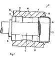
- Fig. 3
- eine fertigmontierte Rolle.
- Die in
Fig. 1 gezeigte Außennabe 1 ist als Hohlzylinder mit einem Mantel 1.1 und zwei Stirnseiten 1.2 und 1.3 als Spritzgussteil aus Polyamid ausgeführt. Während eine der Stirnseiten 1.2 der Außennabe 1 völlig offen ist, ist die andere Stirnseite 1.3 durch eine einstückig mit dem Mantel 1.1 ausgebildete Stirnwand 3 teilgeschlossen, in der eine kreisrunde zentrische Durchtrittsöffnung 4 vorgesehen ist. Die Außennabe 1 wird zu ihrer Komplettierung in eine Spritzgussform eingelegt, und in dieser an die Außenseite des Mantels 1.1 eine elastische Polymerschicht, zum Beispiel eine Gummischicht 5, als Lauffläche angespritzt, die in einer Fortsetzung 6 auf der Außenseite der Stirnwand 3 radial nach innen gezogen ist und in einer kreisrunden Dichtlippe 7 endet, deren Innendurchmesser auf der Innenseite bündig mit der Durchtrittsöffnung 4 abschließt, und von dort aus nach außen hin divergiert und schließlich mit einem Innendurchmesser endet, der geringer ist als der Innendurchmesser der Durchtrittsöffnung 4. - Die in
Fig. 2 gezeigte Innennabe 8 ist ebenfalls als Spritzgussteil aus Polyamid hergestellt. Sie weist einen hohlzylindrischen Mantel 9 auf, dessen Wandstärke deutlich größer ist als die des Mantels 1.1 der Außennarbe 1. Die Innennabe 8 ist auf ihrer Innenseite abgestuft, wodurch zwei Schultern 10 gebildet sind. Diese Schultern 10 bilden Anschläge für die Außenringe von nur schematisch dargestellten Kugellagern 11 und 12. Bei der Vormontage der Rolle 2 wird das Kugellager 11, bezogen auf die zeichnerische Darstellung, mit Presssitz von links soweit in die Innennabe 8 eingeschoben, bis der Außenring des Kugellagers 11 an der ihm zugeordneten Schulter 10 der Innennabe 8 anliegt. Das Kugellager 12 wird in gleicher Weise von rechts in die Innennabe 8 bis zum Anschlag an die ihm zugeordnete Schulter 10 eingeschoben. - In einem weiteren, nicht dargestellten Ausführungsbeispiel ist die Innennabe 8 nicht als Massivkörper sondern als Hohlkörper ausgeführt. Sie weist dazu einen hohlzylindrische Außenmantel und einen hohlzylindrischen Innenmantel auf, wobei Außen- und Innenmantel durch auf den Umfang verteilte, radiale Stege gegeneinander ausgesteift sind. Die Schultern 10 für die Kugellager 11 und 12 sind dann am Innenmantel der Innennabe ausgebildet. Eine derartig ausgeführte Innennabe 8 baut sehr leicht und ist dennoch stabil.
- Nach der Montage der beiden Kugellager 11 und 12 wird, bezogen auf die zeichnerische Darstellung, ein Lagerzapfen 13 in die Innennabe 8 eingeschoben, die die Kugellager 11 und 12 durchsetzt. Der Zapfen 13 ragt aus dem Innenring des Kugellagers 12 hinaus und wird dort durch einen Sprengring 14 gegen Zurückziehen gesichert. An der Außenseite des Kugellagers 11 liegt ein Anpressring 15 an, der durch eine einstückig mit dem Zapfen 13 ausgebildete Schulter 16 in Anlage an das Kugellager 11 gehalten wird. Auf der anderen Seite der Innennabe 8 ist in den Mantel 9 eine Staubkappe 17 eingeschoben, um dort einen staubdichten Abschluss zu erreichen. Dazu ist auf der Innenseite des Mantels 9 eine entsprechende Aussparung 18 vorgesehen. Dieses Einschieben der Staubkappe 17 erfolgt unter Vorspannung, damit ein sicherer Halt der Staubkappe 17 an der Innennabe 8 gewährleistet ist.
- Die derart vormontierte Innennabe 8 wird zur Fertigmontage der Rolle 2 bezogen auf die zeichnerische Darstellung, soweit von links in die Außennabe 1 eingeschoben, bis die Stirnwand 3 an einer Stirnwand 9.1 des Mantels 9 der Innennabe 8 anliegt. Beim Einschieben der Innennabe 8 in Außennabe 9 gelangt schließlich die Dichtlippe 7 in Anlage an die Schulter 16 wie in
Fig. 3 dargestellt ist. Damit ist auch auf dieser Seite eine staubdichte Abdichtung der Rolle 2 gewährleistet. - Eine drehfeste Verbindung zwischen Außennabe 1 und Innennabe 8 wird durch Verkleben hergestellt. Dazu wird vor dem Einschieben der Innennabe 8 in die Außennabe 1 ein geeigneter Klebstoff auf die Außenseite des Mantels 9 der Innennabe 8 aufgetragen.
- Anstelle eines Stoffschlusses kann die drehfeste Verbindung zwischen der Außennabe 1 und der Innennabe 8 auch durch Formschluss oder durch Aufschrumpfen der Außennabe auf die Innennabe hergestellt werden.
- Der Lagerzapfen 13 dient der Befestigung der Rolle 2 an einer Maschine, in der ein Zugriemen aufweisendes Fördermittel Anwendung findet. Der Lagerzapfen 13 kann natürlich auch, abweichend von der obigen Montagefolge, erst dann in die Rolle 2 eingeschoben werden, wenn die Außennabe 1 und die Innennabe 8 miteinander verbunden sind. Das gilt auch für die Staubkappe 17.
Claims (10)
- Tragrolle oder Antriebsrolle für einen Zugriemen eines Fördermittels, aufweisend eine Nabe, die mittels von Kugellagern gelagert und an ihrem Außenumfang mit einer elastischen Polymerschicht als Lauffläche für den Zugriemen versehen ist, dadurch gekennzeichnet, dass die Nabe aus einer hohlzylindrischen Außennabe (1), die die Polymerschicht (5) trägt, und einer hohlzylindrischen Innennabe (8), die die Kugellager (11, 12) aufnimmt, zusammengesetzt ist, wobei die Innennabe (8) in die Außennabe (1) eingeschoben und drehfest mit dieser verbunden ist.
- Rolle nach Anspruch 1, dadurch gekennzeichnet, dass Außennabe (1) und Innennabe (8) durch Stoffschluss miteinander verbunden sind.
- Rolle nach Anspruch 1, dadurch gekennzeichnet, dass Außennabe (1) und Innennabe (8) durch Formschluss miteinander verbunden sind.
- Rolle nach Anspruch 1, dadurch gekennzeichnet, dass Außennabe (1) und Innennabe (8) durch Aufschrumpfen der Außennabe (1) auf die Innennabe (8) miteinander verbunden sind.
- Rolle nach einem der vorstehenden Ansprüche, dadurch gekennzeichnet, dass die Außennabe (1) einen Mantel (1.1) und zwei Stirnseiten (1.2, 1.3) aufweist, wobei eine der Stirnseiten (1.3) durch eine Stirnwand (3) teilgeschlossen ist, in der eine kreisrunde zentrische Durchtrittsöffnung (4) vorgesehen ist.
- Rolle nach Anspruch 5, dadurch gekennzeichnet, dass auf der Außenseite des Mantels (1.1) die Polymerschicht (5) angeordnet ist, die in einer Fortsetzung (6) auf der Außenseite der Stirnwand (3) radial nach innen gezogen ist und in einer kreisrunden Dichtlippe (7) endet.
- Rolle nach Anspruch 6, dadurch gekennzeichnet, dass die Dichtlippe (7) einstückig mit der Polymerschicht (5) hergestellt ist.
- Rolle nach Anspruch 6, dadurch gekennzeichnet, dass die Dichtlippe (7) separat an die Polymerschicht (5) angespritzt ist.
- Rolle nach einem der vorstehenden Ansprüche, dadurch gekennzeichnet, dass die Innennabe (8) einen hohlzylindrischen Außenmantel und einen dazu konzentrisch angeordneten hohlzylindrischen Innenmantel aufweist, die durch auf den Umfang verteilte Stege gegeneinander ausgesteift sind.
- Rolle nach einem der vorstehenden Ansprüche, dadurch gekennzeichnet, dass die Außennabe (1) und die Innennabe (8) als Spritzgussteile aus einem Polymer, z. B. Polyamid, hergestellt sind.
Priority Applications (3)
| Application Number | Priority Date | Filing Date | Title |
|---|---|---|---|
| PL14163052T PL2927165T3 (pl) | 2014-04-01 | 2014-04-01 | Rolka nośna lub rolka napędowa dla pasa pociągowego środka transportowego |
| EP14163052.5A EP2927165B1 (de) | 2014-04-01 | 2014-04-01 | Tragrolle oder Antriebsrolle für einen Zugriemen eines Fördermittels |
| US14/676,632 US9896274B2 (en) | 2014-04-01 | 2015-04-01 | Support roller or drive roller for a drive belt of a conveyor |
Applications Claiming Priority (1)
| Application Number | Priority Date | Filing Date | Title |
|---|---|---|---|
| EP14163052.5A EP2927165B1 (de) | 2014-04-01 | 2014-04-01 | Tragrolle oder Antriebsrolle für einen Zugriemen eines Fördermittels |
Publications (2)
| Publication Number | Publication Date |
|---|---|
| EP2927165A1 true EP2927165A1 (de) | 2015-10-07 |
| EP2927165B1 EP2927165B1 (de) | 2016-10-19 |
Family
ID=50424070
Family Applications (1)
| Application Number | Title | Priority Date | Filing Date |
|---|---|---|---|
| EP14163052.5A Active EP2927165B1 (de) | 2014-04-01 | 2014-04-01 | Tragrolle oder Antriebsrolle für einen Zugriemen eines Fördermittels |
Country Status (3)
| Country | Link |
|---|---|
| US (1) | US9896274B2 (de) |
| EP (1) | EP2927165B1 (de) |
| PL (1) | PL2927165T3 (de) |
Families Citing this family (2)
| Publication number | Priority date | Publication date | Assignee | Title |
|---|---|---|---|---|
| PL2927165T3 (pl) | 2014-04-01 | 2017-06-30 | Arnold Jäger Holding GmbH | Rolka nośna lub rolka napędowa dla pasa pociągowego środka transportowego |
| WO2017103183A2 (de) * | 2015-12-18 | 2017-06-22 | Ketten-Wulf Betriebs-Gmbh | Laufrolle, laufrolleneinrichtung, gelenkkette, sowie die verwendung einer gelenkkette als förderkette |
Citations (5)
| Publication number | Priority date | Publication date | Assignee | Title |
|---|---|---|---|---|
| DE860023C (de) * | 1949-09-06 | 1952-12-18 | Meyer & Co G M B H Maschf | Transportbandrolle |
| DE8024757U1 (de) | 1980-09-16 | 1981-03-12 | Gummi-Jäger KG GmbH & Cie, 30625 Hannover | Tragrolle für Stabbäder |
| WO1998006649A1 (en) * | 1996-08-08 | 1998-02-19 | Arend Jacobus Brink | Idler roller |
| DE20212872U1 (de) * | 2002-08-22 | 2003-02-27 | OTOLSKI Fördertechnik GmbH, 21481 Lauenburg | Tragrolle eines Rollenförderganges |
| DE202005004566U1 (de) * | 2005-03-22 | 2005-06-16 | Internorm Kunststofftechnik Gmbh | Rolle, insbesondere für Bandförderer |
Family Cites Families (17)
| Publication number | Priority date | Publication date | Assignee | Title |
|---|---|---|---|---|
| US1353874A (en) * | 1919-10-20 | 1920-09-28 | Peter C Wego | Bearing for conveyer-rollers |
| US1503920A (en) * | 1922-06-13 | 1924-08-05 | Schneebeli Emil | Roller mounting |
| US2012256A (en) * | 1931-05-14 | 1935-08-27 | Lamson Co | Bearing |
| US2886156A (en) * | 1956-12-28 | 1959-05-12 | Halbron Serge | Rollers for conveyors |
| DE2005211C3 (de) * | 1970-02-05 | 1974-10-31 | Fritz Teske | Tragrolle für Fördervorrichtungen, Förderbänder u.dgl |
| US3648824A (en) * | 1970-09-04 | 1972-03-14 | Charles D Speck | Idler roller device for troughed conveyor belts |
| DE2205242A1 (de) * | 1972-02-04 | 1973-08-09 | Stein Ohg Hans | Rolle |
| DE2205243A1 (de) * | 1972-02-04 | 1973-08-09 | Stein Ohg Hans | Rolle fuer foerderanlagen |
| US5099559A (en) * | 1989-09-25 | 1992-03-31 | Mcgrath Industries Limited | Roller assembly with relative tolerance mountings |
| US5381887A (en) * | 1994-01-12 | 1995-01-17 | Elastomer Specialties, Inc. | Conveyor systems and high durability rollers therefor |
| WO2005080236A2 (en) * | 2004-01-28 | 2005-09-01 | Robert Eichhorn | Idler |
| EP2007662B1 (de) * | 2006-03-31 | 2013-10-23 | Jean-Pierre Gagnon | Zellenförmiges gehäuseschutzsystem für rollenanordnung |
| US20070261933A1 (en) * | 2006-04-26 | 2007-11-15 | Scott C W | Conveyor roller assembly and conveyor roller insert |
| TWM345060U (en) * | 2008-01-30 | 2008-11-21 | Hong Chuan Ind Co Ltd | Transporting roller unit |
| DE102008013131B4 (de) * | 2008-03-07 | 2015-12-31 | Ab Skf | Lageranordnung für eine Tragrolle |
| DE102009017192B4 (de) * | 2009-04-09 | 2011-04-28 | Aktiebolaget Skf | Lageranordnung für eine Tragrolle |
| PL2927165T3 (pl) | 2014-04-01 | 2017-06-30 | Arnold Jäger Holding GmbH | Rolka nośna lub rolka napędowa dla pasa pociągowego środka transportowego |
-
2014
- 2014-04-01 PL PL14163052T patent/PL2927165T3/pl unknown
- 2014-04-01 EP EP14163052.5A patent/EP2927165B1/de active Active
-
2015
- 2015-04-01 US US14/676,632 patent/US9896274B2/en not_active Expired - Fee Related
Patent Citations (5)
| Publication number | Priority date | Publication date | Assignee | Title |
|---|---|---|---|---|
| DE860023C (de) * | 1949-09-06 | 1952-12-18 | Meyer & Co G M B H Maschf | Transportbandrolle |
| DE8024757U1 (de) | 1980-09-16 | 1981-03-12 | Gummi-Jäger KG GmbH & Cie, 30625 Hannover | Tragrolle für Stabbäder |
| WO1998006649A1 (en) * | 1996-08-08 | 1998-02-19 | Arend Jacobus Brink | Idler roller |
| DE20212872U1 (de) * | 2002-08-22 | 2003-02-27 | OTOLSKI Fördertechnik GmbH, 21481 Lauenburg | Tragrolle eines Rollenförderganges |
| DE202005004566U1 (de) * | 2005-03-22 | 2005-06-16 | Internorm Kunststofftechnik Gmbh | Rolle, insbesondere für Bandförderer |
Also Published As
| Publication number | Publication date |
|---|---|
| US9896274B2 (en) | 2018-02-20 |
| PL2927165T3 (pl) | 2017-06-30 |
| EP2927165B1 (de) | 2016-10-19 |
| US20150274432A1 (en) | 2015-10-01 |
Similar Documents
| Publication | Publication Date | Title |
|---|---|---|
| DE2828159C2 (de) | Rollenkäfig für ein Kegelrollenlager | |
| EP0995938B1 (de) | Dichtung für eine Steckverbindung | |
| DE102015105313A1 (de) | Scheibenvorrichtung für Riemen oder Kette, Herstellungsverfahren einer Hohlwelle für eine derartige Vorrichtung und Montageverfahren einer derartigen Vorrichtung | |
| DE102014206658A1 (de) | Federbeinlager mit einer Zweikomponenten Kappe | |
| DE3025705A1 (de) | Kupplungsdrucklager mit selbstzentrierung | |
| EP1106863A1 (de) | Federelement, vorzugsweise Torsionsdämpfer, insb. für Vorrichtung zum Heben und Senken von Kraftfahrzeugfensterscheiben | |
| EP2927165B1 (de) | Tragrolle oder Antriebsrolle für einen Zugriemen eines Fördermittels | |
| DE102020208969A1 (de) | Dichtungsvorrichtung für eine Radnabenanordnung | |
| DE102015220151B4 (de) | Lageranordnung und Dichtung | |
| DE1963079C2 (de) | Abdichtung für die Nadellager der Kreuzgelenkzapfen eines Kardangelenks | |
| EP2058535B1 (de) | Wälzgelagerte Rolle | |
| DE1011788B (de) | Loesbare Kupplung fuer die Mantelhuelsen von Oberwalzen an Spinnmaschinen-Streckwerken | |
| DE2812081A1 (de) | Kunststoffrolle fuer einen bandfoerderer | |
| DE102011003442A1 (de) | Wälzlagerkäfig und Wälzlager | |
| DE19601667A1 (de) | Steckverbindung für den Anschluß von Rohr- und Schlauchleitungen | |
| DE10161987A1 (de) | Tripodegelenkanordnung | |
| DE102008061832A1 (de) | Kugellager | |
| DE102009025130A1 (de) | Dichtelement für ein Drehlager | |
| EP1862681B1 (de) | Lauf- und Spannrolle für Transportbänder zur Verwendung bei Bandförderern von Rotationsfalzanlagen | |
| DE972476C (de) | Gehaeuseloser Dichtring fuer Lager und andere umlaufende Maschinenteile | |
| DE3238634C2 (de) | Förderbandtragrolle | |
| DE1525153C3 (de) | Zweistoff-Fensterkäfig für Wälzlager | |
| DE102009024163A1 (de) | Kraftübertragungsvorrichtung | |
| DE2706073C3 (de) | Nabenkappe zum Verschluß der Radlager bei Kraftfahrzeugen | |
| DE102006013046A1 (de) | Gelenk- und/oder Lageranordnung |
Legal Events
| Date | Code | Title | Description |
|---|---|---|---|
| PUAI | Public reference made under article 153(3) epc to a published international application that has entered the european phase |
Free format text: ORIGINAL CODE: 0009012 |
|
| AK | Designated contracting states |
Kind code of ref document: A1 Designated state(s): AL AT BE BG CH CY CZ DE DK EE ES FI FR GB GR HR HU IE IS IT LI LT LU LV MC MK MT NL NO PL PT RO RS SE SI SK SM TR |
|
| AX | Request for extension of the european patent |
Extension state: BA ME |
|
| 17P | Request for examination filed |
Effective date: 20160323 |
|
| RBV | Designated contracting states (corrected) |
Designated state(s): AL AT BE BG CH CY CZ DE DK EE ES FI FR GB GR HR HU IE IS IT LI LT LU LV MC MK MT NL NO PL PT RO RS SE SI SK SM TR |
|
| GRAP | Despatch of communication of intention to grant a patent |
Free format text: ORIGINAL CODE: EPIDOSNIGR1 |
|
| INTG | Intention to grant announced |
Effective date: 20160506 |
|
| GRAS | Grant fee paid |
Free format text: ORIGINAL CODE: EPIDOSNIGR3 |
|
| GRAA | (expected) grant |
Free format text: ORIGINAL CODE: 0009210 |
|
| AK | Designated contracting states |
Kind code of ref document: B1 Designated state(s): AL AT BE BG CH CY CZ DE DK EE ES FI FR GB GR HR HU IE IS IT LI LT LU LV MC MK MT NL NO PL PT RO RS SE SI SK SM TR |
|
| REG | Reference to a national code |
Ref country code: GB Ref legal event code: FG4D Free format text: NOT ENGLISH |
|
| REG | Reference to a national code |
Ref country code: CH Ref legal event code: EP |
|
| REG | Reference to a national code |
Ref country code: AT Ref legal event code: REF Ref document number: 838123 Country of ref document: AT Kind code of ref document: T Effective date: 20161115 |
|
| REG | Reference to a national code |
Ref country code: IE Ref legal event code: FG4D Free format text: LANGUAGE OF EP DOCUMENT: GERMAN |
|
| REG | Reference to a national code |
Ref country code: DE Ref legal event code: R096 Ref document number: 502014001731 Country of ref document: DE |
|
| REG | Reference to a national code |
Ref country code: NL Ref legal event code: FP |
|
| REG | Reference to a national code |
Ref country code: LT Ref legal event code: MG4D |
|
| PG25 | Lapsed in a contracting state [announced via postgrant information from national office to epo] |
Ref country code: LV Free format text: LAPSE BECAUSE OF FAILURE TO SUBMIT A TRANSLATION OF THE DESCRIPTION OR TO PAY THE FEE WITHIN THE PRESCRIBED TIME-LIMIT Effective date: 20161019 |
|
| REG | Reference to a national code |
Ref country code: FR Ref legal event code: PLFP Year of fee payment: 4 |
|
| PG25 | Lapsed in a contracting state [announced via postgrant information from national office to epo] |
Ref country code: SE Free format text: LAPSE BECAUSE OF FAILURE TO SUBMIT A TRANSLATION OF THE DESCRIPTION OR TO PAY THE FEE WITHIN THE PRESCRIBED TIME-LIMIT Effective date: 20161019 Ref country code: NO Free format text: LAPSE BECAUSE OF FAILURE TO SUBMIT A TRANSLATION OF THE DESCRIPTION OR TO PAY THE FEE WITHIN THE PRESCRIBED TIME-LIMIT Effective date: 20170119 Ref country code: LT Free format text: LAPSE BECAUSE OF FAILURE TO SUBMIT A TRANSLATION OF THE DESCRIPTION OR TO PAY THE FEE WITHIN THE PRESCRIBED TIME-LIMIT Effective date: 20161019 Ref country code: GR Free format text: LAPSE BECAUSE OF FAILURE TO SUBMIT A TRANSLATION OF THE DESCRIPTION OR TO PAY THE FEE WITHIN THE PRESCRIBED TIME-LIMIT Effective date: 20170120 |
|
| PG25 | Lapsed in a contracting state [announced via postgrant information from national office to epo] |
Ref country code: ES Free format text: LAPSE BECAUSE OF FAILURE TO SUBMIT A TRANSLATION OF THE DESCRIPTION OR TO PAY THE FEE WITHIN THE PRESCRIBED TIME-LIMIT Effective date: 20161019 Ref country code: IS Free format text: LAPSE BECAUSE OF FAILURE TO SUBMIT A TRANSLATION OF THE DESCRIPTION OR TO PAY THE FEE WITHIN THE PRESCRIBED TIME-LIMIT Effective date: 20170219 Ref country code: PT Free format text: LAPSE BECAUSE OF FAILURE TO SUBMIT A TRANSLATION OF THE DESCRIPTION OR TO PAY THE FEE WITHIN THE PRESCRIBED TIME-LIMIT Effective date: 20170220 Ref country code: FI Free format text: LAPSE BECAUSE OF FAILURE TO SUBMIT A TRANSLATION OF THE DESCRIPTION OR TO PAY THE FEE WITHIN THE PRESCRIBED TIME-LIMIT Effective date: 20161019 Ref country code: RS Free format text: LAPSE BECAUSE OF FAILURE TO SUBMIT A TRANSLATION OF THE DESCRIPTION OR TO PAY THE FEE WITHIN THE PRESCRIBED TIME-LIMIT Effective date: 20161019 Ref country code: HR Free format text: LAPSE BECAUSE OF FAILURE TO SUBMIT A TRANSLATION OF THE DESCRIPTION OR TO PAY THE FEE WITHIN THE PRESCRIBED TIME-LIMIT Effective date: 20161019 |
|
| REG | Reference to a national code |
Ref country code: DE Ref legal event code: R097 Ref document number: 502014001731 Country of ref document: DE |
|
| PG25 | Lapsed in a contracting state [announced via postgrant information from national office to epo] |
Ref country code: SK Free format text: LAPSE BECAUSE OF FAILURE TO SUBMIT A TRANSLATION OF THE DESCRIPTION OR TO PAY THE FEE WITHIN THE PRESCRIBED TIME-LIMIT Effective date: 20161019 Ref country code: RO Free format text: LAPSE BECAUSE OF FAILURE TO SUBMIT A TRANSLATION OF THE DESCRIPTION OR TO PAY THE FEE WITHIN THE PRESCRIBED TIME-LIMIT Effective date: 20161019 Ref country code: EE Free format text: LAPSE BECAUSE OF FAILURE TO SUBMIT A TRANSLATION OF THE DESCRIPTION OR TO PAY THE FEE WITHIN THE PRESCRIBED TIME-LIMIT Effective date: 20161019 Ref country code: DK Free format text: LAPSE BECAUSE OF FAILURE TO SUBMIT A TRANSLATION OF THE DESCRIPTION OR TO PAY THE FEE WITHIN THE PRESCRIBED TIME-LIMIT Effective date: 20161019 Ref country code: CZ Free format text: LAPSE BECAUSE OF FAILURE TO SUBMIT A TRANSLATION OF THE DESCRIPTION OR TO PAY THE FEE WITHIN THE PRESCRIBED TIME-LIMIT Effective date: 20161019 |
|
| PLBE | No opposition filed within time limit |
Free format text: ORIGINAL CODE: 0009261 |
|
| STAA | Information on the status of an ep patent application or granted ep patent |
Free format text: STATUS: NO OPPOSITION FILED WITHIN TIME LIMIT |
|
| PG25 | Lapsed in a contracting state [announced via postgrant information from national office to epo] |
Ref country code: SM Free format text: LAPSE BECAUSE OF FAILURE TO SUBMIT A TRANSLATION OF THE DESCRIPTION OR TO PAY THE FEE WITHIN THE PRESCRIBED TIME-LIMIT Effective date: 20161019 Ref country code: BG Free format text: LAPSE BECAUSE OF FAILURE TO SUBMIT A TRANSLATION OF THE DESCRIPTION OR TO PAY THE FEE WITHIN THE PRESCRIBED TIME-LIMIT Effective date: 20170119 |
|
| 26N | No opposition filed |
Effective date: 20170720 |
|
| PG25 | Lapsed in a contracting state [announced via postgrant information from national office to epo] |
Ref country code: SI Free format text: LAPSE BECAUSE OF FAILURE TO SUBMIT A TRANSLATION OF THE DESCRIPTION OR TO PAY THE FEE WITHIN THE PRESCRIBED TIME-LIMIT Effective date: 20161019 |
|
| REG | Reference to a national code |
Ref country code: CH Ref legal event code: PL |
|
| REG | Reference to a national code |
Ref country code: IE Ref legal event code: MM4A |
|
| PG25 | Lapsed in a contracting state [announced via postgrant information from national office to epo] |
Ref country code: MC Free format text: LAPSE BECAUSE OF FAILURE TO SUBMIT A TRANSLATION OF THE DESCRIPTION OR TO PAY THE FEE WITHIN THE PRESCRIBED TIME-LIMIT Effective date: 20161019 |
|
| PG25 | Lapsed in a contracting state [announced via postgrant information from national office to epo] |
Ref country code: CH Free format text: LAPSE BECAUSE OF NON-PAYMENT OF DUE FEES Effective date: 20170430 Ref country code: LU Free format text: LAPSE BECAUSE OF NON-PAYMENT OF DUE FEES Effective date: 20170401 Ref country code: LI Free format text: LAPSE BECAUSE OF NON-PAYMENT OF DUE FEES Effective date: 20170430 |
|
| REG | Reference to a national code |
Ref country code: FR Ref legal event code: PLFP Year of fee payment: 5 |
|
| PG25 | Lapsed in a contracting state [announced via postgrant information from national office to epo] |
Ref country code: IE Free format text: LAPSE BECAUSE OF NON-PAYMENT OF DUE FEES Effective date: 20170401 |
|
| PG25 | Lapsed in a contracting state [announced via postgrant information from national office to epo] |
Ref country code: MT Free format text: LAPSE BECAUSE OF FAILURE TO SUBMIT A TRANSLATION OF THE DESCRIPTION OR TO PAY THE FEE WITHIN THE PRESCRIBED TIME-LIMIT Effective date: 20161019 |
|
| PG25 | Lapsed in a contracting state [announced via postgrant information from national office to epo] |
Ref country code: HU Free format text: LAPSE BECAUSE OF FAILURE TO SUBMIT A TRANSLATION OF THE DESCRIPTION OR TO PAY THE FEE WITHIN THE PRESCRIBED TIME-LIMIT; INVALID AB INITIO Effective date: 20140401 |
|
| PG25 | Lapsed in a contracting state [announced via postgrant information from national office to epo] |
Ref country code: CY Free format text: LAPSE BECAUSE OF FAILURE TO SUBMIT A TRANSLATION OF THE DESCRIPTION OR TO PAY THE FEE WITHIN THE PRESCRIBED TIME-LIMIT Effective date: 20161019 |
|
| PG25 | Lapsed in a contracting state [announced via postgrant information from national office to epo] |
Ref country code: MK Free format text: LAPSE BECAUSE OF FAILURE TO SUBMIT A TRANSLATION OF THE DESCRIPTION OR TO PAY THE FEE WITHIN THE PRESCRIBED TIME-LIMIT Effective date: 20161019 |
|
| PG25 | Lapsed in a contracting state [announced via postgrant information from national office to epo] |
Ref country code: TR Free format text: LAPSE BECAUSE OF FAILURE TO SUBMIT A TRANSLATION OF THE DESCRIPTION OR TO PAY THE FEE WITHIN THE PRESCRIBED TIME-LIMIT Effective date: 20161019 |
|
| PG25 | Lapsed in a contracting state [announced via postgrant information from national office to epo] |
Ref country code: AL Free format text: LAPSE BECAUSE OF FAILURE TO SUBMIT A TRANSLATION OF THE DESCRIPTION OR TO PAY THE FEE WITHIN THE PRESCRIBED TIME-LIMIT Effective date: 20161019 |
|
| REG | Reference to a national code |
Ref country code: AT Ref legal event code: MM01 Ref document number: 838123 Country of ref document: AT Kind code of ref document: T Effective date: 20190401 |
|
| PG25 | Lapsed in a contracting state [announced via postgrant information from national office to epo] |
Ref country code: AT Free format text: LAPSE BECAUSE OF NON-PAYMENT OF DUE FEES Effective date: 20190401 |
|
| PGFP | Annual fee paid to national office [announced via postgrant information from national office to epo] |
Ref country code: PL Payment date: 20250321 Year of fee payment: 12 |
|
| PGFP | Annual fee paid to national office [announced via postgrant information from national office to epo] |
Ref country code: NL Payment date: 20250422 Year of fee payment: 12 |
|
| PGFP | Annual fee paid to national office [announced via postgrant information from national office to epo] |
Ref country code: DE Payment date: 20250605 Year of fee payment: 12 |
|
| PGFP | Annual fee paid to national office [announced via postgrant information from national office to epo] |
Ref country code: BE Payment date: 20250422 Year of fee payment: 12 |
|
| PGFP | Annual fee paid to national office [announced via postgrant information from national office to epo] |
Ref country code: FR Payment date: 20250422 Year of fee payment: 12 |
|
| PGFP | Annual fee paid to national office [announced via postgrant information from national office to epo] |
Ref country code: GB Payment date: 20260324 Year of fee payment: 13 |
|
| PGFP | Annual fee paid to national office [announced via postgrant information from national office to epo] |
Ref country code: IT Payment date: 20260121 Year of fee payment: 13 |