EP2927308A1 - Installation de biogaz et procédé de production de biogaz à partir de paille - Google Patents
Installation de biogaz et procédé de production de biogaz à partir de paille Download PDFInfo
- Publication number
- EP2927308A1 EP2927308A1 EP15000919.9A EP15000919A EP2927308A1 EP 2927308 A1 EP2927308 A1 EP 2927308A1 EP 15000919 A EP15000919 A EP 15000919A EP 2927308 A1 EP2927308 A1 EP 2927308A1
- Authority
- EP
- European Patent Office
- Prior art keywords
- straw
- biogas
- fermenter
- fermentation
- bunker
- Prior art date
- Legal status (The legal status is an assumption and is not a legal conclusion. Google has not performed a legal analysis and makes no representation as to the accuracy of the status listed.)
- Granted
Links
Images






Classifications
-
- C—CHEMISTRY; METALLURGY
- C12—BIOCHEMISTRY; BEER; SPIRITS; WINE; VINEGAR; MICROBIOLOGY; ENZYMOLOGY; MUTATION OR GENETIC ENGINEERING
- C12M—APPARATUS FOR ENZYMOLOGY OR MICROBIOLOGY; APPARATUS FOR CULTURING MICROORGANISMS FOR PRODUCING BIOMASS, FOR GROWING CELLS OR FOR OBTAINING FERMENTATION OR METABOLIC PRODUCTS, i.e. BIOREACTORS OR FERMENTERS
- C12M21/00—Bioreactors or fermenters specially adapted for specific uses
- C12M21/16—Solid state fermenters, e.g. for koji production
-
- C—CHEMISTRY; METALLURGY
- C12—BIOCHEMISTRY; BEER; SPIRITS; WINE; VINEGAR; MICROBIOLOGY; ENZYMOLOGY; MUTATION OR GENETIC ENGINEERING
- C12M—APPARATUS FOR ENZYMOLOGY OR MICROBIOLOGY; APPARATUS FOR CULTURING MICROORGANISMS FOR PRODUCING BIOMASS, FOR GROWING CELLS OR FOR OBTAINING FERMENTATION OR METABOLIC PRODUCTS, i.e. BIOREACTORS OR FERMENTERS
- C12M21/00—Bioreactors or fermenters specially adapted for specific uses
- C12M21/04—Bioreactors or fermenters specially adapted for specific uses for producing gas, e.g. biogas
-
- C—CHEMISTRY; METALLURGY
- C12—BIOCHEMISTRY; BEER; SPIRITS; WINE; VINEGAR; MICROBIOLOGY; ENZYMOLOGY; MUTATION OR GENETIC ENGINEERING
- C12M—APPARATUS FOR ENZYMOLOGY OR MICROBIOLOGY; APPARATUS FOR CULTURING MICROORGANISMS FOR PRODUCING BIOMASS, FOR GROWING CELLS OR FOR OBTAINING FERMENTATION OR METABOLIC PRODUCTS, i.e. BIOREACTORS OR FERMENTERS
- C12M23/00—Constructional details, e.g. recesses, hinges
- C12M23/44—Multiple separable units; Modules
-
- C—CHEMISTRY; METALLURGY
- C12—BIOCHEMISTRY; BEER; SPIRITS; WINE; VINEGAR; MICROBIOLOGY; ENZYMOLOGY; MUTATION OR GENETIC ENGINEERING
- C12M—APPARATUS FOR ENZYMOLOGY OR MICROBIOLOGY; APPARATUS FOR CULTURING MICROORGANISMS FOR PRODUCING BIOMASS, FOR GROWING CELLS OR FOR OBTAINING FERMENTATION OR METABOLIC PRODUCTS, i.e. BIOREACTORS OR FERMENTERS
- C12M29/00—Means for introduction, extraction or recirculation of materials, e.g. pumps
- C12M29/02—Percolation
-
- Y—GENERAL TAGGING OF NEW TECHNOLOGICAL DEVELOPMENTS; GENERAL TAGGING OF CROSS-SECTIONAL TECHNOLOGIES SPANNING OVER SEVERAL SECTIONS OF THE IPC; TECHNICAL SUBJECTS COVERED BY FORMER USPC CROSS-REFERENCE ART COLLECTIONS [XRACs] AND DIGESTS
- Y02—TECHNOLOGIES OR APPLICATIONS FOR MITIGATION OR ADAPTATION AGAINST CLIMATE CHANGE
- Y02E—REDUCTION OF GREENHOUSE GAS [GHG] EMISSIONS, RELATED TO ENERGY GENERATION, TRANSMISSION OR DISTRIBUTION
- Y02E50/00—Technologies for the production of fuel of non-fossil origin
- Y02E50/30—Fuel from waste, e.g. synthetic alcohol or diesel
Definitions
- the present invention relates to a biogas plant and more particularly to a biomass power plant for biogas production according to the preamble of claim 1 and to a process for producing biogas from straw.
- the present invention is based on the ideas for a biogas plant, in particular for a biomass power plant and for a process for the production of biogas, which solve the problem of obtaining suitable fermentation substrates in sufficient quantities, especially for larger, industrial-scale plants to economic conditions and process.
- a device for the mechanical digestion and possibly chemical and / or thermal digestion of straw is provided in the biogas plant.
- biogas production in particular biogas production after the solidification process, becomes accessible to a new class of renewable resources.
- straw is available in large quantities and is available at low cost.
- the straw can be used as a supplement to the conventional fresh mass, such as silage from green waste, silage from whole cereal crops, etc., thus providing itself to a variety of large and very large biomass power plants, with for example 20 or more fermenters and a respective electric Power of over 5,000 kW to economic conditions safely.
- the means for thermal digestion of straw comprises a device for saturated steam treatment.
- the device for saturated steam treatment preferably comprises a pressure vessel and means adapted to generate a water vapor in the pressure vessel, with a pressure which is between 20 and 30 bar and a temperature which is between 180 ° C and 250 ° C. Saturated steam treatment takes place at the pressures and temperatures described and typically lasts for 5 to 15 minutes. The function of the saturated steam treatment will be described using the example of wheat straw.
- Wheat straw consists of about 40% cellulose, 23% arabinoxylan (hemicellulose) and 21% lignin, with all three main components taking on a tightly packed structure.
- the main obstacle to the biochemical utilization of cellulose and hemicellulose is lignin, which is indigestible to microorganisms and blocks the bacteria from accessing cellulose and hemicellulose.
- lignin In saturated steam treatment, the lignin structures are softened or melted, but during the relatively short treatment time essentially not triggered from the stalks. After the saturated steam treatment, the lignin solidifies again.
- the lignin is thus changed primarily in its microscopic structure, but it is not dissolved out of the straws.
- the structure of the straws remains as such.
- This represents a difference to the thermal pressure hydrolysis which is carried out under basically similar conditions, but for longer periods, and in which a real hydrolysis takes place, that is, a dissolution of previously solid or dry substances in water.
- a thermal pressure hydrolysis The structure of the straws is dissolved, resulting in a syrupy suspension.
- the device for digesting straw comprises a container for soaking it before the saturated steam treatment, for example in water.
- the drawn-in water evaporates abruptly, rupturing ligno-cellulose structures and making the cellulose even more accessible to the bacteria.
- a device for mechanical comminution of the straw through which the straw can be mechanically digested before the saturated steam treatment, for example by shredding. This further contributes to the dissolution of the lignin structures and facilitates the subsequent fermentation.
- the straw is ground, preferably in a hammer mill. This form of disruption mechanically destroys the lignin structures. Milling alone, however, is not useful when using the Feststoffvergärungsvons because otherwise a doughy porridge would form, which adheres to the digestate and prevents percolation.
- the straw can also be digested in a bale shape, which in particular substantially facilitates its transport and handling, as explained in more detail below. Since the structure is preserved, for example, of straws under the saturated steam treatment, straw bales also retain their shape under the saturated steam treatment and can be transported easily and efficiently after this.
- a particular advantage of bales is also that they can be layered at the bottom in a Garagenfermenter, which can increase the filling level of the fermenter. In principle, the filling level of the fermenter is limited by the fact that from a certain height of the substrate in the fermenter, the pressure at the bottom of which is so high that the substrate is too compacted to allow percolate to seep through.
- straw bale layers which are introduced into a fermenter at the bottom, are far more pressure-stable than conventional fermentation substrates. Even under high pressure, the straw bale layer is still permeable to percolate, so that the usual filling level in the fermenter can still be filled up on the straw bale layer.
- the fermenters can therefore be constructed higher by the height of the straw bale position than usual, what the fermenter-specific technology costs (gate, gas technology, sensors, flaps and openings, percolate nozzles, drains, piping, pumps etc.) keeps constant and increases the efficiency of the biogas plant as a whole.
- means for perforating the bales are provided in an advantageous development.
- the means for perforating are preferably adapted to perforate a bale from two sides so that the holes formed in the perforation from one side and the holes formed in the perforation from the other side are separated by material bridges.
- the device for saturated steam treatment comprises at least one skewer on which a straw ball is skewered, wherein the skewer has an inner cavity into which water vapor can be introduced, and a plurality of openings through which the water vapor can escape from the cavity ,
- the hot and high pressure water vapor used in the saturated steam treatment can be introduced into the bale through the spit, thereby causing the saturated steam atmosphere to also reach the material inside the bale to an excellent degree.
- the problem may arise that the air present in the bale is compressed in an inner portion of the bale but does not mix with the steam fast enough So that the saturated steam treatment is less effective in this inner portion of the bale.
- a water vapor permeable container is preferably provided in the pressure vessel for storage thereof. Further, means are preferably provided for transporting the water vapor permeable container into and out of the pressure vessel, for example rails or a roller conveyor.
- the pressure vessel has an upper opening through which it can be charged with loose straw, and a lower opening through which the loose straw can fall out of the container permeable to water vapor.
- a "quasi continuous saturated steam treatment in which the loose straw is poured batchwise into the container, the pressure vessel is then closed for saturated steam treatment, then the treated loose material is dropped from the container through the lower opening and finally a subsequent charge through the upper opening is dropped into the container.
- the device for saturated steam treatment may comprise a plurality of pressure vessels, which are interconnected by pipelines.
- a plurality of pressure vessels by a single source of steam, for example, a single steam reservoir, supplied, which significantly increases the efficiency, especially for larger power plants.
- the device for digesting straw comprises a container for soaking it in a water-lye solution, a water-acid solution, percolate or manure.
- This soaking is an example of the above-mentioned chemical pulping.
- This soaking can be carried out in particular after the saturated steam treatment, both with loose straw and with bale-like straw, the bales in this case preferably being perforated in the manner described above.
- This soaking initiates a (mildly aerobic) prehydrolysis, which takes place prior to introduction into the fermenter.
- the soaked straw after soaking and prior to introduction into the fermenter can preferably be heated to 30 to 50 °. This heating can be combined with the transport of the straw from the device for digestion to the fermenter, as explained in more detail below.
- This prehydrolysis accelerates the subsequent anaerobic bacterial fermentation in the fermenter.
- the structure of the biogas plant and the process for producing biogas with the digestion methods described here can be done without the addition of additional yeasts, fungi or enzymes.
- the lignocellulosic material alone is left to autohydrolysis and bacterial hydrolysis.
- the use of bacteria instead of yeasts, fungi or enzymes is much more economical since the chemical and biochemical processes are faster in bacterial hydrolysis than in enzymatic ones.
- significant costs for their procurement and handling are saved over the external use of enzymes and / or acids.
- the supply of fermentation substrate can however also be ensured for much larger plants, since, for example, straw accumulates in cereal crops in far greater quantities than is currently required, and there It can be relatively economically transported with appropriate (large) technology over long distances.
- the greater the throughput of the biogas plant the more the investment and operating costs for a device for breaking up the straw are worthwhile.
- a contextual relationship between the possibility of digestion of the straw and the size of the biogas plant is insofar as the means for digesting the straw contributes significantly to ensure the supply of larger biogas plants with fermentation substrate, and on the other hand, the size of the biogas plant and the use of low-priced substrate type Straw makes the investment for the device for the digestion in particular and the large biomass power plant as a whole first economical.
- the facilities for the digestion of straw in a delivery and loading area of the biogas plant are housed.
- the delivery and loading area preferably comprises stationary conveyor technology, which is suitable for conveying fresh material from the delivery and loading area to a fermenter forecourt, from which a plurality of fermenters of the garage type is accessible.
- stationary conveyor technology is provided according to this development, through which even large quantities of fresh mass can be efficiently transported to the fermenter forecourt to be introduced from there into the fermenter.
- stationary conveyor technology allows einhausen the entire biogas plant, whereby an odor nuisance of the environment is avoided and it is possible to operate the biogas plant in the vicinity of residential areas.
- the delivery and loading area is effectively an interface between the enclosed interior of the plant and the outside area, and is thus arranged in an outer section of the plant.
- the fermenter forecourt is centrally located in the plant for logistical reasons. Due to the stationary conveyor technology, the fresh mass or the fermentation substrate can be brought from Vorinerund loading area to Fermentervorplatz without transport vehicles would be required to produce the exhaust within the housing area and would also increase the operating costs. Preferably, there is a slight negative pressure in the delivery and loading area, so that even when delivering fresh mass and loading of digestate only little air penetrates to the outside, and thus the odor nuisance is minimal.
- first conveying means are preferably provided, which are suitable for conveying fresh material from the at least one delivery bunker for fresh mass to a fresh-material bunker.
- first conveying means may comprise, for example, screw conveyors, elevators and conveyor belts, on which the fresh material from different delivery bunkers are conveyed to the fresh-material bunker.
- the delivery and loading area preferably comprises second conveying means, in particular a thrust plate, which are suitable for conveying the fresh material through the fresh-food bunker in the direction of the fermenter forecourt.
- the fresh-material bunker has a dual function: on the one hand it serves as a transport route from the delivery area to the fermenter forecourt, on the other hand it serves as a buffer for fresh mass. It is important that the fresh mass, which was introduced first in the Frischmassebunker, this also leaves first. This means that the fresh mass, which is delivered to the fermenter forecourt, always about the same age and thus pre-hydrolyzed equally strong. This results in a substrate consistency, which is advantageous for the subsequent fermentation.
- the delivery and loading area comprises in an advantageous development of a discharge point for straw, and in particular straw in bale shape.
- a crane is preferably provided which is suitable for gripping and transporting bale material.
- the means for digesting straw are provided which is of one of the types described above.
- the means for digestion as described above may be formed so that the bale shape is maintained, so that the pre-treated by digestion straw can be transported in bale form from the delivery and loading area to Fermentervorplatz, what the transport and the introduction into the fermenter very efficient.
- third conveying means in particular roller conveyors or push conveyors, are provided, which are suitable for conveying individual bales or packages of bales along a bale duct to the fermenter forecourt.
- bale material is very efficiently transported from the periphery to the fermentor forecourt by the third conveyor and bale channel, allowing high throughput with very low operating costs.
- a converter is arranged at the fermenter front near the end of the bale channel, which is suitable to remove packages of bales from the bale channel and handed over to a wheel loader or forklift as a package.
- the delivery bunker, the fresh bunker and / or the bale duct are heatable, and advantageously by means of waste heat, which is generated by one or more gas engines.
- waste heat which is generated by one or more gas engines.
- the fresh mass temperature losses are compensated, which arise during the Gärmassenauffrischung the waste material. This will accelerate the reintroduction of biogas production after the refreshment of the digestate.
- this makes the above-described weakly aerobic prehydrolysis possible, which shortens the time until complete fermentation of the fermentation mass and increases the plant output (the substrate throughput) and thus the economic efficiency.
- a digestate bunker which is accessible from the fermenter forecourt for introducing fermentation residues.
- the digestate bunker preferably contains stationary conveying means which are suitable for transporting fermentation residues through the digestate bunker.
- stationary conveying means are formed by screw conveyors, which are arranged at the ends of the digestate bunker.
- the digestate bunker is preferably sized to handle the expected amount of digestate of at least two days.
- the digestate bunker has a threefold function. First, it serves as a buffer for fermentation residues, and secondly, it provides the fermentation residue transport device from the central fermentor forecourt to the periphery. Due to the sufficient size of the digestate bunker ensures that the digestate for at least two days can not be collected on weekends when truck traffic is restricted. Finally, a post-fermentation takes place in the digestate bunker as a third function, and therefore it is connected to the biogas system. Thus, from the digestate further biogas is obtained, which would be lost in a simpler design.
- a Schüttrog for fermentation residues is preferably arranged at the entrance end of the digestate bunker.
- the digestate can thus be poured directly from the fermenter forecourt into the Schüttrog; they are then automatically transported to the periphery.
- a device for dehydrating the fermentation residues is provided at the outlet end of the digestate bunker.
- the digestate is nutrient and bacteria-rich percolate, which can be introduced via a loop into the percolate flow tanks described below, if needed. If such percolate is needed, it is squeezed out of the digestate at the dehydrator and fed to the percolate circulation tanks via the loop. Otherwise, the dehydrator may be bypassed and the wet fermentation residues removed as they are.
- a drying system for drying digestate may be provided, which preferably uses waste heat of a gas Otto engine for drying the digestate.
- a gasification plant is preferably provided which is suitable for producing wood or lean gas from dried fermentation residues by the process of wood gasification, in particular based on carbonization or pyrolysis. This lean gas can then be added to the biogas produced by the fermentation.
- the downstream gasification of the fermentation residues can once again generate around 20% of the biogas production as wood / lean gas, which substantially increases the efficiency of the raw material for gas production.
- the gasification of the fermentation residues makes it possible to increase the gas yield, if this should be lower by an imperfect digestion of the straw than would be possible biologically.
- just lignin-containing substances are suitable for wood gasification.
- the use of straw as a fermentation substrate and the subordinate wood gasification of digestate ideally complement one another.
- the straw is mechanically digested by grinding, whereby the lignin structures are also torn open. If, for example, ground straw were introduced into a wet fermentation plant, according to investigations by the inventor, contrary to the view prevalent in the art, this would result in a considerable additional gas yield. Due to the grinding, the two-dimensional lignin structures are also destroyed. The cellulose and arabinoxylan may then be dissolved by the aqueous organic acids contained in the fermentation mass, which are also present in the slurry typically present in wet fermentation plants and, to an even greater extent, in pure wet grass wetland wetland plants. As a result, so far regarded as unfit biomass for the anaerobic methane-producing bacteria is accessible.
- a similarly simple method of chemical digestion is also possible in biogas plants for solidification.
- the straw is already mixed days before the introduction into the fermenter with other fresh material, preferably with solid manure.
- the urea present in the solid manure can in turn dissolve the lignin and make the cellulose and arabinoxylan accessible for hydrolysis.
- additionally or separately provided lignified renewable raw materials LHNawaRo
- the mixing of the loose lignin-containing material with the solid manure would typically take place with a greater time interval before the introduction into the fermenter, preferably a few days.
- layers of solid manure and layers of lignin-containing material can be set up alternately in the fermenter without a time advance, it also being possible for layers of other, not strongly lignified, NawaRos to intervene therebetween.
- the urea of the upper solid manure layer with the percolate can penetrate into the layer containing the lignin-containing material and at least partially dissolve the two-dimensional lignin structures.
- the acidic percolate ensures that the two-dimensional lignin structures at least partially dissolve and that the material delivers biogas, albeit not with the yield that spreads through the others can be achieved above described process for digestion, in particular saturated steam treatment.
- the inoculation material which comes back into the fermenter together with the fresh mass before being mixed by means of a mechanical press, such as a screw press, Maschinenwalßt and pressed, whereby the material is at least partially mechanically digested and also possibly integrated nutrients for the anaerobic , Bacterial fermentation be made available.
- the screw press can be designed to be mobile, for example, be arranged on a low loader, so that they can be driven on the fermenter forecourt to the relevant fermenter.
- a device for thermal pressure hydrolysis is also provided, with which the material can be subjected to a thermal pressure hydrolysis both before and after the solids fermentation plant has been passed, but before the digestate is disposed of.
- the thermal pressure hydrolysis takes place under similar conditions as the saturated steam treatment described above, but for a longer period of time, for example 60 to 120 minutes.
- the lignin is completely released, so that forms a syrupy suspension.
- true hydrolysis that is, splitting of polymers into monomers by physical action of water and heat, takes place.
- the syrupy suspension may then be returned to the fermentation process or sold to companies producing second generation fuels from this material. It also utilizes the lignin content and other, un-valued organic matter. This is not possible with an anaerobic, bacterial fermentation.
- a biomass power plant (BMKW) 10 as an embodiment of a biogas plant according to a development of the invention will be described in detail.
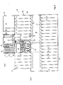
- Fig. 6 the ground plan of the BMKW 10 is shown.
- Fig. 7 shows an enlarged partial area of the floor plan of Fig. 10 , in which a power and heat generation plant of the BMKW is shown.
- Fig. 8 shows another part of the plan of Fig. 6 , in which a delivery and loading area is shown enlarged.
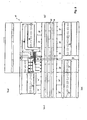
- Fig. 9 shows a plan view of the upper floor of the BMKW 10.
- the BMKW 10 is divided into a base portion 12 and an expansion portion 14.
- the base portion 12 includes 18 fermenters of the garage type, which are arranged in two rows, in the illustration of Fig. 5 in a northern and a southern row. Located between the two rows of fermenters 16 a Fermentervorplatz 18, to which the gates 20 of the fermenter 16 open. It should be noted that for the sake of clarity, not all the fermenters 16 and fermenter ports 20 are provided with reference numerals in the figures.
- the base portion 12 includes a power and heat generating plant 22, which in Fig. 7 shown enlarged and described in more detail below.
- the base portion 12 includes a delivery and loading area 24, which in Fig. 8 is shown enlarged and also described in more detail below.
- the entire base portion 12 is enclosed by a hall structure to which in particular a Fermentervorplatz (FVP) -Hallenabites 26 and a delivery and Verlade Schlenabites 28 belongs, as in particular Fig. 1, 4th and 5 easy to recognize.
- FVP Fermentervorplatz
- the entire hall construction or enclosure of the base section 12 is vented by a large central venting system, so that there is always a slight negative pressure relative to the atmospheric pressure inside the hall construction.
- the expansion section 14 essentially consists of 11 additional fermenters 16 'and an extension of the FVP hall section 26.
- the expansion section 14 serves to provide, if necessary, up to 11 additional fermenters 16'.
- the BMKW 10 has a modular design, which is advantageous for achieving an optimal end configuration, because the exact biogas yield depends on a variety of factors, including the nature of the existing fresh mass, and is not theoretically accurately predictable.
- the northern and southern fermenter rows are connected by a technology bridge 30, which in particular in Fig. 5 . 6 and 9 you can see.
- the technology bridge 30 straddles the FVP 18 at a height that allows wheel loaders, of which in Fig. 5 two shown as examples are able to drive under it even with fully extended loading shovel, without that they can touch and damage the technology bridge.
- the upper floor of the BMKW 10 comprises three film gas storage 32 in the base section 12 and two further film gas storage 32 'in the expansion section 14.
- the film gas storage 32 are in the cross-sectional views of Fig. 5 and 15 easy to recognize. They take on the manner described in more detail below the biogas, which is generated in the fermenters 16 and 16 '.
- the upper floor comprises five percolate circulation tanks (PUT) 34 in the base section 12 and four PUTs 34 'in the expansion section 14, which are also shown in the cross-sectional views of FIG Fig. 5 good to see.
- PUT 34 is located above each of three fermenters 16 and receives percolate from them, which is collected at the bottom of the fermenters and pumped into the PUT 34.
- percolate refers to the liquid, manure-like component of the fermentation substance.
- an exhaust gas cooling room 31 located on the upper floor, an exhaust gas cooling room 31, a southern technical room 36 and a northern technical room 38, which are interconnected by the technology bridge 30.
- an exhaust gas cooling room 31 located on the upper floor, an exhaust gas cooling room 31, a southern technical room 36 and a northern technical room 38, which are interconnected by the technology bridge 30.
- the Fermentervorplatz (FVP) 18 is located in the center of the BMKW 10. It serves as a transport route for fresh mass to the respective fermenters 16, 16 'or of digestate substance from the fermenters 16, 16'. In addition, it serves as Anmisch Structure on which the contents of a fermenter is spread, taken from about a fifth to a quarter as digestate and to compensate for this withdrawal and the loss of mass resulting from the gasification, about one-third is supplemented by fresh mass and mixed with the old fermentation mass.
- This work can be done on the FVP 18 by a large wheel loader, as in Fig. 5 is shown schematically.
- a grated gutter into which seepage fluids and released percolate flow.
- the gutter has a collection well (not shown) from which the resulting liquids are conveyed to one of the PUTs 34 via a percolate loop (not shown).
- the delivery and loading area 24 is in Fig. 8 shown enlarged in plan.
- four delivery bunkers 42 are provided in the embodiment shown, which are housed by the delivery and loading area Hall section 28.
- a truck can maneuver backwards into the hauled-in delivery bunker and tip or dump the fresh bulk cargo into the delivery bunker 42 there. Since there is a slight underpressure throughout the delivery and loading area 24, hardly any unpleasant odors leave the enclosure to the outside.
- Each delivery bunker 42 has a downwardly tapered bottom, at the lowest point of one or more double screw conveyor (not shown) are provided which promotes the fresh mass horizontally to a bucket elevator (not shown), which conveys the fresh mass onto a conveyor belt 44 , or directly on a lower conveyor belt.
- the fresh mass is dropped into a Frischmassebunker 46. Since the fresh mass is conveyed from four or more different bunkers on the same conveyor belt 44 and thrown onto the same heap in the fresh mass bunker 46, the fresh mass is automatically mixed.
- the Frischmassebunker 46 is an elongated chamber that connects the delivery and loading area 24 with the Fermentervorplatz 18, in particular in Fig. 6 you can see.
- the Frischmassebunker 46 has a floor heating, with the fresh mass already on a Temperature of 42 ° C is heated so that the fermentation mass within a fermenter 16, 16 ', which is supplemented by the fresh mass, is not cooled by this, so that the fermentation process after closing the fermenter 16 starts again quickly and possibly even already weakly aerobic prehydrolysis can take place, which shortens the fermentation time and increases the system performance (throughput of fermentation substrate) and the efficiency of the plant.
- the fresh mass bunker 46 has a dual function. First, it serves as an intermediate or buffer storage for loose fresh mass. On the other hand, it serves as a transport path between the delivery and loading area 24, ie the periphery of the BMKWs 10, and the centrally located Fermentervorplatz 18.
- a push plate or slider arranged (not shown) of each new from above poured bulk loose fresh mass towards the Fermentervorplatz 18 pushes. Then the slide is moved back to make room for new fresh mass.
- This sliding mechanism ensures that the fresh mass is pushed out of the fermenter in the same order in which it was introduced at the entrance into the Frischmassebunker 46, on the side of the Fermentervorplatzes 18 out of it. This means that the fresh mass that reaches the Fermentervorplatz 18, always about the same age and therefore of constant quality, which is advantageous for the subsequent fermentation.
- the delivery and loading area 24 comprises a section for the delivery and transport of structural or bale material, in particular for straw.
- This section for delivering and transporting bale material comprises a preparation space 48, a bale delivery space 50, a digestion area 52 and an intermediate storage 54.
- this area of the delivery and loading area 24 will be described with reference to straw as a highly lignified, bale-shaped structural material. but it is understood that this section can also be used for the delivery, processing and onward transport of other bale-shaped structural material.
- a crane (not shown) is mounted on a track so that it can pick up and drop straw bales in each of the spaces 48-54.
- the bales of straw are delivered to the straw delivery room 50 and transported by the crane (not shown) to the intermediate storage 54.
- the digestion region 52 Before the straw is conveyed to the fermentor forecourt 18, it is pretreated in the digestion region 52, namely digested.
- the digestion of the straw is necessary because the Straw is heavily lignified, and the bacteria in the fermenter 16 due to the lignin-crusted cellulose only very poorly get to the lignin trapped nutrients.
- the straw can be digested in different ways.
- the straw may be chemically disrupted by soaking it in a container containing water, a water-caustic solution or a water-acid solution.
- the soaking causes the lignin, which has largely enclosed the cellulose, to be partially dissolved.
- the cellulose is no longer hidden behind a lignin crust, but accessible to the hydrolysis and the bacteria.
- the straw in the digestion region 52 may be otherwise disrupted, for example mechanically using a hammer mill or by being subjected to thermal pressure, i. heated to 180 ° C to 250 ° C for five to ten minutes at high pressure, for example, 20 to 30 bar.
- thermal pressure i. heated to 180 ° C to 250 ° C for five to ten minutes at high pressure, for example, 20 to 30 bar.
- the lignin solidifies again, but in the form of very small globules with gaps between them, which open the way for the autohydrolytic, organic acids and for the anaerobic bacteria to the nutrients of the straw.
- Another embodiment is an extension of the thermal printing treatment in which the pressure in the corresponding container is suddenly reduced, whereby the water evaporates in the straw structures and expands very rapidly.
- the lignin structures are torn and the nutrients for the anaerobic bacteria are exposed. Further details of the straw digestion are given in the following section.
- a roller conveyor 56 onto which individual bales of straw and / or straw bales are laid by the crane (not shown) and which conveys the straw bales to the fermentor forecourt 18 through a straw channel 58 arranged parallel to the fresh meal hopper 46 (see FIG Fig. 6 ).
- both the loose fresh mass and the fresh bale mass are transported by stationary conveyor technology from the delivery and loading area 24 to the fermenter forecourt 18.
- stationary conveyor technology makes the Frischmassebunker 46 and the straw channel 58, the connection between the central Fermentervorplatz 18 and the peripheral delivery and loading area 24 ready, and this transport is done completely in the housed BMKW 10.
- the transport with the stationary conveyor technology is suitable for high throughputs and in particular faster, more space-saving and less expensive than a delivery with wheel loaders.
- the straw channel 58 and the Frischmassebunker 46 ends at a central location of the fermenter forecourt 18, so that the paths between the fermentervorplatznessen end of Frischmassebunkers 46 and straw channel 58 and the fermenter 16 to be supplied are generally short.
- the digestion of the straw in the digestion region 52 makes it possible to use straw, despite its high lignin content, as a fermentation substrate. This is extremely advantageous because straw in crop production anyway incurred, and not enough use for this exists.
- the BMKW 10 is designed for renewable raw materials, it makes sense to grow in the vicinity of the BMKW 10 specifically for use in the BMKW 10 suitable raw materials, which, however, are generally not intended for food. However, this poses a certain conflict of objectives because a certain proportion of the limited land available is always reserved for food production.
- the use of straw as a fermentation substrate is a very attractive solution, since straw, which is produced during grain production, allows the simultaneous production of food and biomass suitable for power plants.
- straw has another advantage.
- the filling level in fermenters is limited by the pressure that results at the bottom of the fermenter: this pressure must always be so low that the fermentation substrate is still permeable to percolate.
- this pressure must always be so low that the fermentation substrate is still permeable to percolate.
- the entire usual filling level can be layered on this layer of fermentation substance, since the straw bale layer even at the pressure then permeable to Percolate is.
- This lowermost straw layer thus represents an additional amount of fermentation substrate which can be used in a fermenter, so that the Plant performance (room capacity measured in new substrate per fermenter and day) is significantly increased.
- the straw bales are placed in packages of eight straw bales on the roller conveyor 56, which are two bales wide and four bales high. These packages are transported as a whole through the straw channel 58 and lifted at the end of the Fermentervorplatz 18 by a converter (not shown) and passed to a wheel loader or forklift, which also receives the packages as a whole or in two parts and brings to the fermenter. From these packages can be relatively easily and quickly built said bottom straw bale layer.
- a digestate bunker 60 is provided which extends parallel to the fresh material bunker between the Fermentervorplatz 18 and the delivery and loading area 24.
- the digestate bunker 60 has at its Fermentervorplatz the end facing a Schütttrog 62 for digestate, which forms the entrance into the Gärrestebunker 60.
- this Schütttrog 62 fermentation residues are tilted by a wheel loader. From there they are pressed into the digestate bunker by means of a screw conveyor. Due to the discontinuous reprints of more and more fermentation residues, the mass is slowly transported through the digestate bin 60 to the other end, where they are transported by further screw conveyors from the digestate bunker 60.
- the digestate bunker 60 has a triple function. On the one hand, it serves as a transport path between the fermenter forecourt 18 in the center of the BMKW 10 and the delivery and loading area, with similar advantages, as they have been described with respect to the Frischmassebunker 46 and the straw channel 58. On the other hand, the digestate bunker 60 also serves as a thermophilically operated secondary fermenter and acts more or less like another fermenter. Therefore, the digestate bunker 60 is also connected to the biogas system.
- the digestate bunker 60 serves as a buffer for fermentation residues. It is so dimensioned that it holds at least as much digestate as can be accumulated in two days. This makes it possible to carry out the removal of the resulting digestate on weekdays, so that the removal is not hindered by truck driving restrictions.
- a switch 64 is provided, which makes it possible to transport the fermentation residues either directly via a conveyor belt 66 to loading silos 68, or to take the detour via a dehydrating device 70.
- the dehydrating device 70 is a screw press which is suitable for pressing water or percolate from the fermentation residues and introducing them into one of the PUTs 34. Whether the detour is taken via the dehydrator 70 depends on the current need for percolate.
- the loading silos for digestate 68 are high silos, which are arranged on trapezoidal frames, so that a truck can drive under the silos 68 and thus can be easily loaded.
- a conventional drying plant for example a drum or belt dryer (not shown) is provided, which is suitable for drying the fermentation residues to less than 25%, preferably to 15%, water content.
- the heat for the drying plant is preferably provided by the waste heat from the generator sets.
- a gasification plant (not shown) is provided, in which the dried fermentation residues are subjected to a so-called wood gasification, in which flammable wood gas (lean gas) is obtained from the dried digestate by pyrolysis or partial combustion under air deficiency. This wood or lean gas is fed after the removal of the tar resulting from the wood gas by any known method in the biogas system and can then be used without any problems as a fuel for the gasoline engines.
- the energy content of the wood gas reduces the demand for biogas by up to 20%, possibly even more, so that for the same power output up to 20% or possibly up to 30% less substrate must be used for the fermentation. As a result, the profitability of the system as a whole increases considerably.
- the straw is delivered in the delivery and loading area 24 and digested in the digestion area 52 and possibly additionally in the staging area 48.
- straw in this embodiment of the invention is straw as LHNawaRo delivered in bale form and also open in bale shape, to be finally introduced in bale shape in the garage fermenter 16.
- the bales preferably have a density of over 200 kg / m 3 , which can be produced only with ultra-high pressure balers.
- the advantage of such a high density of straw bales is that then the capacity of a truck is optimally utilized both in terms of the permissible weight of the load and the possible volume of the load, so that the straw can be delivered over longer distances to economic conditions.
- part of the straw can be put into the digestion form "grinding" and / or into the digestion form "thermal pressure hydrolysis".
- the combination of the various forms of digestion is particularly advantageous because each has its advantages and disadvantages for the practice. The combination achieves the best overall effect.
- the milled straw leads to a particularly high gas yield, but the proportion in relation to the fresh mass is limited insofar as the powdered straw wetted by percolate forms a sticky mass, which must be mixed because of the handling with sufficient fresh mass.
- the fermentation substrate as a whole consists of ground straw.
- between 5% and 35% of the straw used in total is ground and thereby mechanically digested.
- the perforation of straw bales serves to make the interior of the straw bale accessible for soaking, for saturated steam treatment and for subsequent soaking in percolate.
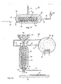
- the straw bales are perforated from two sides, as with reference to FIG Fig. 10 is explained in more detail.
- Fig. 10 shows above a perspective view of a straw bale 72, in which on the underside 74 is looked.
- the lower figure shows a perspective view of the same straw bale 72, is looked at on the top 76.
- the straw bale 72 is perforated by a first set of holes 78 that do not pass through the entire bale 72.
- the straw bale 72 is perforated from the top 76 with a second set of holes 80 that also do not pass through the entire straw bale 72.
- the holes 78 and 80 are offset from each other so that the holes of the first set 78 and the holes of the second set 80 are separated by material bridges.
- suitable containers are provided for soaking straw bales, which are not shown in the illustration.
- the size of the container for soaking are matched to the dimensions of the straw bales, so that the soaking can be carried out space-saving and efficient.
- a device for saturated steam treatment is provided in the digestion region 52 or in the preparation space 48.
- various facilities for saturated steam treatment are described, which can be used in the system shown or a modified system.
- Fig. 11 shows a schematic cross-sectional view of a simple structure of a device 82 for saturated steam treatment.
- the device 82 comprises a pressure vessel 84 with a lid 83 which is articulated via a hinge 85 pivotally mounted on the pressure vessel 84.
- a feeding device for the straw is indicated schematically and designated by reference numeral 87.
- the feeder 87 may be formed by, for example, a conveyor belt or a roller conveyor.
- the feeder 87 may be rails on which a loose material container 89 may be pushed into the pressure vessel 84.
- the container 89 is permeable to water vapor, but is capable of holding the loose material and may be, for example, an open-topped lattice container or basket.
- the lid 83 of the pressure vessel 84 can be closed by a closing mechanism 91.
- the lid 83 is pivoted to open the pressure vessel 84 inwardly, as for example in Fig. 14 can be seen, so that the lid 83 is pressed by the pressure in the interior of the pressure vessel 84 in the closed position and thereby easier sealed.
- the pressure vessel 84 is connected to a supply line 93 and a supply valve 95, through which saturated steam 102 at a pressure of up to 30 bar and a temperature of up to 250 ° C from a steam reservoir (not shown) are introduced into the pressure vessel 84 can. Further, the pressure vessel 84 is connected to an outlet line 97 with an outlet valve 98, through which the steam can be discharged from the pressure vessel 84 after the saturated steam treatment. Further, a compressor 100 is arranged in the outlet conduit 97, with which the saturated steam 102 in the reservoir (not shown) can be returned.
- the saturated steam treatment method will be described with reference to the saturated steam treatment device 82 of FIG Fig. 11 explained.
- the lignin-containing material 106 is introduced as a bale or loose material in a container as in the container 89 in the pressure vessel 84 and the pressure vessel 84 is closed. Thereafter, the valve 95 is opened in the supply line 93, so that hot steam at a temperature of 180 ° C to 250 ° C and a high pressure of between 20 and 30 bar from a steam reservoir (not shown) is introduced into the pressure vessel 84.
- the introduced saturated steam is in Fig. 11 indicated schematically and designated by the reference numeral 102.
- the lignin-containing material 106 is exposed to the saturated steam 102 for 5 to 15 minutes.
- the lignin in the material is melted but not released from the material.
- the material e.g. the straw was soaked in the second step above, because the water is already present in the material and only needs to be heated, which shortens the treatment time.
- the saturated steam is discharged through the outlet conduit 97 from the pressure vessel 84.
- This release of pressure preferably occurs abruptly, so that the pressure decreases by at least 80% within 5 seconds or less. Due to the rapid lowering of the pressure, the water in the structures of the lignin-containing material abruptly evaporates and expands rapidly.
- the lignin structures of the straw are torn so that the nutrients (cellulose and arabinoxylan) become accessible to aqueous organic acids and the anaerobic bacteria.
- the lignin-containing material 106 is removed from the pressure vessel 84, and it cools down. Upon cooling, the molten lignin hardens again. However, upon solidification of the lignin, the original planar structures do not re-form, but rather coagulate in a droplet structure that allows spaces through which first organic acids and then bacteria can pass to the cellulose and arabinoxylan (hemicellulose).
- Fig. 11 Basically, the structure of the saturated steam treatment device 82 can be modified in a variety of ways, and some examples of such modifications are given below. In this case, identical or functionally identical components with the same reference numerals as in Fig. 11 and their description is not repeated.
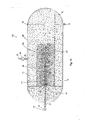
- Fig. 12 shows a structure of a device for saturated steam treatment, which is designed for a quasi-continuous processing of loose material.
- a container 89 is provided for loose material 106 inside the pressure vessel 84, but this is permanently installed in the pressure vessel 84.
- a pressure-resistant slide 108 is opened so that the lignin-containing material 106 falls from a funnel 110 into the container 88. If there is a sufficient amount of material 106 in the container 89, the pressure resistant slide 108 is closed and the saturated steam treatment takes place in the same manner as described with reference to FIGS Fig. 11 has been described.
- a saturated steam reservoir 102 is shown which has a heater 114.
- the steam is discharged via the outlet conduit 97 and forced into the reservoir 112 via the compressor 100. Thereafter, another pressure-resistant slide 108 is opened at the lower end of the container, and the digested loose material 106 falls onto a conveyor belt 116 for further transport.
- a liquid mass 117 which is referred to as "slurry" and which is discharged via a further line 118 and passed via a line 120 in the percolate circulation tanks (not shown).
- Fig. 13 shows a further embodiment 122 of a device for saturated steam treatment, which is designed especially for the treatment of bale material, in particular straw bales 72.
- the structure is basically similar to the structure of Fig. 11 and will not be described again. The main difference, however, is that a spit or spike 124 is provided which has an inner cavity 126 and nozzle-like openings 128 connected to this inner cavity 126.
- the inner cavity 126 is in fluid communication with the supply line 93.
- the saturated steam treatment device 122 of Fig. 13 In operation of the saturated steam treatment device 122 of Fig. 13 is a straw bale 72 and 106 via the feed device 87, which is formed in the illustrated embodiment by a roller conveyor, in the illustration of Fig. 13 from the right into the pressure vessel 84 introduced and skewered on the skewer 124. Then, the pressure vessel 84 is closed as before, and the saturated steam 102 is injected via the supply line 93, the inner cavity 126 of the spit 124 and the nozzle-like openings 128 in the straw bale 72. This ensures that the interior of the straw bale 72 comes into effective contact with the saturated steam. Namely, the saturated steam as in Fig.
- the five pressure vessels 84 includes, similar to the device 122 of Fig. 13 are provided with spits 124. However, in the device 130 of Fig. 14 the pressure vessels 84 are arranged vertically so that the bales of straw can be introduced into the pressure vessels from above with a crane 132.
- the crane 132 comprises a trolley 134 and a rack 136 having an upper bale 138 and a lower grab 140 are formed for a lower bale.
- All pressure vessels 84 of Fig. 14 are connected via a pipeline to the same pressure reservoir 112. It will be similar to in Fig. 13 the saturated steam 102 is introduced via the feed line 92 through the spit 124 and through the straw bales 72 into the pressure vessel 84.
- Fig. 14 The training of Fig. 14 is designed for a high throughput plant where saturated steam treatment can be carried out very efficiently.
- the pretreated bales are soaked in percolate, which is a weakly acidic solution.
- the bales may be soaked in a weakly alkaline solution such as caustic soda.
- the bales are heated to about 40 ° C, which can be accomplished, for example, that the straw channel 46 (s. Fig. 8 ) is heated by waste heat of the gas Otto engines.
- a weakly aerobic prehydrolysis is initiated, through which the subsequent anaerobic bacterial fermentation is further accelerated.
- the anaerobic bacteria are at the same place of fresh material, which is also beneficial.
- the straw digestion process described herein achieves that the pretreated material in the fermenters provides substantial gas yield with moderate residence times, and does so without adding additional enzymes, fungi or yeasts.
- the natural acid content of the straw (around 3 to 4%) dissolves the solid cellulose and converts it into an aqueous solution (autohydrolysis).
- the biogenic polymers are biochemically cleaved by the action of the organic acid chemically and / or by the influence of bacteria in low-molecular compounds (monosaccharides, amino acids, short-chain peptides, long-chain fatty acids, glycerol). These are present in water-dissolved form at the end of the phase. However, this happens without first enzymes, bacteria or yeasts must be added.
- the lignocellulosic material in this embodiment is left alone to autohydrolysis and bacterial hydrolysis.
- LHNawaRo is mixed with liquid manure or solid manure before being introduced into the fermenter, but it may already be sufficient if LHNawaRos and solid manure are stacked in alternating layers in the fermenter, optionally with intervening layers of other, non-lignified NawaRos, wherein the urea of the upper layers of solid manure with the percolate penetrates into the layer containing the lignin-containing material and thus at least partially dissolves the two-dimensional lignin structures. This represents a very simple case of chemical disruption.
Landscapes
- Health & Medical Sciences (AREA)
- Life Sciences & Earth Sciences (AREA)
- Chemical & Material Sciences (AREA)
- Engineering & Computer Science (AREA)
- Organic Chemistry (AREA)
- Zoology (AREA)
- Wood Science & Technology (AREA)
- Bioinformatics & Cheminformatics (AREA)
- Genetics & Genomics (AREA)
- Sustainable Development (AREA)
- General Health & Medical Sciences (AREA)
- Microbiology (AREA)
- Biomedical Technology (AREA)
- Biotechnology (AREA)
- Biochemistry (AREA)
- General Engineering & Computer Science (AREA)
- Molecular Biology (AREA)
- Oil, Petroleum & Natural Gas (AREA)
- General Chemical & Material Sciences (AREA)
- Clinical Laboratory Science (AREA)
- Processing Of Solid Wastes (AREA)
- Preparation Of Compounds By Using Micro-Organisms (AREA)
- Treatment Of Sludge (AREA)
- Fertilizers (AREA)
Applications Claiming Priority (3)
| Application Number | Priority Date | Filing Date | Title |
|---|---|---|---|
| DE102007029700A DE102007029700A1 (de) | 2007-06-27 | 2007-06-27 | Biomasse-Kraftwerk |
| EP07786393.4A EP2167631B1 (fr) | 2007-06-27 | 2007-07-27 | Installation de biogaz et procédé de production de biogaz à partir de matières premières ligneuses |
| PCT/EP2007/006681 WO2009000305A1 (fr) | 2007-06-27 | 2007-07-27 | Installation de biogaz et procédé de production de biogaz à partir de matières premières ligneuses |
Related Parent Applications (2)
| Application Number | Title | Priority Date | Filing Date |
|---|---|---|---|
| EP07786393.4A Division EP2167631B1 (fr) | 2007-06-27 | 2007-07-27 | Installation de biogaz et procédé de production de biogaz à partir de matières premières ligneuses |
| EP07786393.4A Division-Into EP2167631B1 (fr) | 2007-06-27 | 2007-07-27 | Installation de biogaz et procédé de production de biogaz à partir de matières premières ligneuses |
Publications (2)
| Publication Number | Publication Date |
|---|---|
| EP2927308A1 true EP2927308A1 (fr) | 2015-10-07 |
| EP2927308B1 EP2927308B1 (fr) | 2020-03-18 |
Family
ID=39154372
Family Applications (5)
| Application Number | Title | Priority Date | Filing Date |
|---|---|---|---|
| EP15000919.9A Active EP2927308B1 (fr) | 2007-06-27 | 2007-07-27 | Installation de biogaz et procédé de production de biogaz à partir de paille |
| EP15001025.4A Active EP2927309B1 (fr) | 2007-06-27 | 2007-07-27 | Installation de biogaz et procédé de production de biogaz à partir de paille |
| EP07786393.4A Revoked EP2167631B1 (fr) | 2007-06-27 | 2007-07-27 | Installation de biogaz et procédé de production de biogaz à partir de matières premières ligneuses |
| EP07846568.9A Not-in-force EP2160458B1 (fr) | 2007-06-27 | 2007-11-13 | Installation de biogaz et procédé de production de biogaz à partir de paille avec pelletisation des résidus de fermentation |
| EP07856639.5A Withdrawn EP2162526A1 (fr) | 2007-06-27 | 2007-12-12 | Installation de biogaz avec digestion de solides et production de méthane dans une cuve de recirculation de percolat |
Family Applications After (4)
| Application Number | Title | Priority Date | Filing Date |
|---|---|---|---|
| EP15001025.4A Active EP2927309B1 (fr) | 2007-06-27 | 2007-07-27 | Installation de biogaz et procédé de production de biogaz à partir de paille |
| EP07786393.4A Revoked EP2167631B1 (fr) | 2007-06-27 | 2007-07-27 | Installation de biogaz et procédé de production de biogaz à partir de matières premières ligneuses |
| EP07846568.9A Not-in-force EP2160458B1 (fr) | 2007-06-27 | 2007-11-13 | Installation de biogaz et procédé de production de biogaz à partir de paille avec pelletisation des résidus de fermentation |
| EP07856639.5A Withdrawn EP2162526A1 (fr) | 2007-06-27 | 2007-12-12 | Installation de biogaz avec digestion de solides et production de méthane dans une cuve de recirculation de percolat |
Country Status (8)
| Country | Link |
|---|---|
| US (1) | US9963665B2 (fr) |
| EP (5) | EP2927308B1 (fr) |
| DE (4) | DE102007029700A1 (fr) |
| DK (1) | DK2167631T3 (fr) |
| ES (1) | ES2558364T3 (fr) |
| HU (1) | HUE027343T2 (fr) |
| PL (1) | PL2167631T3 (fr) |
| WO (3) | WO2009000305A1 (fr) |
Cited By (1)
| Publication number | Priority date | Publication date | Assignee | Title |
|---|---|---|---|---|
| EP3354718A1 (fr) | 2017-01-30 | 2018-08-01 | HERBST Umwelttechnik GmbH | Procédé et dispositif destinés a la production de biogaz |
Families Citing this family (44)
| Publication number | Priority date | Publication date | Assignee | Title |
|---|---|---|---|---|
| DE102007029700A1 (de) | 2007-06-27 | 2009-01-08 | Michael Feldmann | Biomasse-Kraftwerk |
| MY171315A (en) | 2007-12-21 | 2019-10-08 | Inbicon As | Non-sterile fermentation of bioethanol |
| DE102009024287B4 (de) | 2008-06-23 | 2019-04-25 | Hochschule Ostwestfalen-Lippe | Verfahren der Biogasgewinnung |
| US20120040328A1 (en) * | 2009-01-28 | 2012-02-16 | Michael Niederbacher | Fermenter feed system for fermentable biomass of a biogas system and method for operating the feed system |
| PL2218704T3 (pl) * | 2009-02-16 | 2015-07-31 | Kompoferm Gmbh | Instalacja fermentacyjna i sposób jej eksploatacji |
| DE102009009920A1 (de) * | 2009-02-18 | 2010-08-26 | Meyer, Herwig, Dipl.-Landw. | Einrichtung zur verbesserten Gasausbeute durch weiteren Aufschluss von organischer Biomasse in Biogasanlagen |
| DE102009020200A1 (de) * | 2009-05-07 | 2010-11-11 | Niederbacher, Michael, Dr. | Verfahren zum Betreiben einer Biogasanlage sowie Biogasanlage |
| DE102009045895A1 (de) * | 2009-10-21 | 2011-04-28 | Planungsbüro Rossow Gesellschaft für Versorgungstechnik mbH | Verfahren und Vorrichtung zur Erhöhung der Besiedlungsdichte von methanbildenden Bakterienstämmen in Biogasfermentern |
| DE102009050867A1 (de) * | 2009-10-27 | 2011-04-28 | Vsr Industrietechnik Gmbh | Verfahren zur Erzeugung von Biogas durch Trockenfermentation sowie Biogasanlage zur Gewinnung von Biogas durch Trockenfermentation |
| DE102010005253B4 (de) * | 2010-01-20 | 2024-02-08 | Bts Biogas Srl/Gmbh | Verfahren und Vorrichtung zum Behandeln und/oder Aufbereiten von flüssigem Gärrest aus einem Nachgärer und/oder Fermenter einer Biogasanlage |
| DE102010017818A1 (de) | 2010-02-17 | 2011-08-18 | Meissner, Jan A. | Verfahren und Anlage zur Herstellung von CBM (Compressed BioMethane) als treibhausgasfreier Kraftstoff |
| DE102011113646B3 (de) * | 2011-09-19 | 2013-01-03 | Prüf- und Forschungsinstitut Pirmasens e.V. | Vorrichtung und Verfahren zum hydrothermalen Aufschluss von getrockneten, verholzten Lignocellulose-haltigen Biomassen |
| DE102011055695A1 (de) * | 2011-11-24 | 2013-05-29 | Renergon International AG | Vorrichtung zur Fermentation organischer Feststoffe |
| DK177818B1 (da) * | 2012-04-11 | 2014-08-11 | C F Nielsen As | Fremgangsmåde til behandling af en biomasse med et indhold af lignocellulose |
| DE102012016951B4 (de) * | 2012-08-28 | 2014-11-06 | Yoen Ok Roth | Vorrichtung und Verfahren für die Fermentation mikrobieller Kulturen |
| US9523102B2 (en) * | 2012-09-13 | 2016-12-20 | Novus Energy Llc | Methods of anaerobic digestion of biomass to produce biogas |
| DE102012109821A1 (de) * | 2012-10-15 | 2014-04-17 | Renergon International AG | Verfahren und Vorrichtung zur Erzeugung von Biogas |
| DE102012222590A1 (de) | 2012-12-07 | 2014-06-12 | Planungsbüro Rossow Gesellschaft für erneuerbare Energien mbH | Biogaserzeugung durch mehrstufige fermentation in einem monobehälter |
| DE102012112898A1 (de) * | 2012-12-21 | 2014-06-26 | Verbio Vereinigte Bioenergie Ag | Verfahren und Anlage zur Herstellung von Biogas aus lignocellulosehaltiger Biomasse |
| EP2792739B1 (fr) * | 2013-04-15 | 2021-03-24 | BTS Biogas Srl/GmbH | Installation de biogaz dotée d'un dispositif d'alimentation en ferments |
| DE102013107683B4 (de) * | 2013-07-18 | 2017-10-12 | Peter Lutz | Biogasanlage zur Erzeugung von Biogas aus nicht-pumpbarer Biomasse sowie Verfahren zu ihrem Betrieb |
| DE102014005270A1 (de) | 2014-04-09 | 2015-10-15 | Christine Apelt | Verfahren zur Befähigung von Methanfermentationsanlagen zur stofflichen und energetischen Verwertung von lignocellulosehaltigen biogenen Einsatzstoffen und Anordnung zur Durchführung des Verfahrens |
| DE102014011479A1 (de) * | 2014-07-31 | 2016-02-04 | Christoph Bürger | Neues Verfahren zur Vergärung biogener Energieträger |
| CN104384170B (zh) * | 2014-10-23 | 2016-08-24 | 长沙学院 | 一种生物处理城市有机垃圾及农业有机废物的工艺及装置 |
| US20160185633A1 (en) * | 2014-12-30 | 2016-06-30 | University Of Florida Research Foundation, Inc. | Recovery of nutrients from water and wastewater by precipitation as struvite |
| GB2546243B (en) * | 2015-12-23 | 2018-07-11 | Aerothermal Green Energy Ltd | Biomass, thermal pressure hydrolysis and anaerobic digestion |
| DE102017005627A1 (de) | 2016-10-07 | 2018-04-12 | Lennart Feldmann | Verfahren und System zur Verbesserung der Treibhausgas-Emissionsminderungsleistung biogener Kraft-, Heiz- und Brennstoffe und/oder zur Anreicherung landwirtschaftlich genutzter Flächen mit Humus-C |
| WO2018064993A1 (fr) | 2016-10-09 | 2018-04-12 | Archea New Energy Gmbh | Système multichambre conçu pour générer un biogaz |
| US12098504B2 (en) * | 2016-11-02 | 2024-09-24 | Tab Holding Aps | Methods and devices for processing lignocellulosic biomass using mechanical pretreatment to enhance feedstock hydration properties |
| FI130177B (en) * | 2019-02-22 | 2023-03-29 | Erkki Kalmari | Procedure for the production of biogas and arrangements related thereto |
| CN110004186B (zh) * | 2019-03-19 | 2020-12-15 | 上海市环境科学研究院 | 一种秸秆干式厌氧发酵快速启动及稳定运行方法 |
| NL2022866B1 (nl) * | 2019-04-04 | 2020-10-08 | Macondo B V | Inrichting voor het bewerken en homogeniseren van een massa los of weinig samenhangend materiaal |
| FR3102989B1 (fr) * | 2019-11-07 | 2021-10-15 | Eric Goubin | Procédé et installation de génération de matière première pour des installations de méthanisation à partir de déchets de matière organique contenant une majorité de plantes herbacées |
| CN111778292A (zh) * | 2020-06-22 | 2020-10-16 | 四川华地康生态农业有限公司 | 一种农业固废生物发酵方法 |
| CN113105997B (zh) * | 2021-04-14 | 2022-07-01 | 河北省农业科技发展中心 | 能够抽取沼液的厌氧发酵装置 |
| EP4323308A4 (fr) | 2021-04-15 | 2025-04-23 | Iogen Corporation | Procédé et système de production d'hydrogène renouvelable à faible intensité de carbone |
| EP4326671A4 (fr) | 2021-04-22 | 2024-11-06 | Iogen Corporation | Procédé et système de production de combustible |
| DE102021126275A1 (de) * | 2021-10-11 | 2023-04-13 | Clemens Maier | Regeneratives Speicherkraftwerk mit Rückführung von Biomaterial |
| CN114271395B (zh) * | 2022-01-05 | 2024-06-28 | 赣州美园畜牧有限公司 | 一种猪饲料混合发酵加工方法及其加工装置 |
| US11807530B2 (en) | 2022-04-11 | 2023-11-07 | Iogen Corporation | Method for making low carbon intensity hydrogen |
| CN115926948A (zh) * | 2022-12-19 | 2023-04-07 | 中国华电科工集团有限公司 | 一种厨余垃圾资源化利用装置及方法 |
| US12264068B2 (en) | 2023-04-04 | 2025-04-01 | Iogen Corporation | Method for making low carbon intensity hydrogen |
| CN116925894A (zh) * | 2023-07-17 | 2023-10-24 | 安徽万恩沼气科技有限公司 | 一种全发酵沼气装置 |
| CN119161960B (zh) * | 2024-10-17 | 2025-06-20 | 无棣鲁兴养殖设备股份有限公司 | 一种畜禽废弃物收集发酵装置 |
Citations (9)
| Publication number | Priority date | Publication date | Assignee | Title |
|---|---|---|---|---|
| DE2730671A1 (de) * | 1977-07-07 | 1979-01-25 | Trienekens Fa Matthias | Verfahren und anlage zur muellaufbereitung sowie dafuer geeignetes maschinengestell |
| EP0286100A1 (fr) * | 1987-04-08 | 1988-10-12 | Rea Gesellschaft Für Recycling Von Energie Und Abfall Mbh | Procédé et dispositif de traitement et digestion anaérobique de matières biogéniques |
| DE4308920A1 (de) * | 1993-03-19 | 1994-09-22 | Linde Kca Dresden Gmbh | Vorrichtung zur Behandlung von Bioabfällen oder dergleichen |
| EP0934998A2 (fr) * | 1998-02-09 | 1999-08-11 | Manfred Prof. Dr. Hoffmann | Procédé et dispositif pour la méthanisation de biomasses |
| DE10021383A1 (de) * | 2000-05-03 | 2001-11-08 | Wea Waste Energy Action Intern | Verfahren und Vorrichtung zur vollständigen und schadstoffreien Konversion von Reststoffgemengen |
| US20030176669A1 (en) * | 2000-07-10 | 2003-09-18 | Thorre Doug Van | Process for obtaining bio-functional fractions from biomass |
| WO2004016797A1 (fr) * | 2002-08-14 | 2004-02-26 | Tekniska Verken I Linköping Ab | Procede et appareil de production de biogaz a partir d'une matiere organique |
| US20060024801A1 (en) * | 2004-06-16 | 2006-02-02 | The Texas A & M University System | Methods and systems for biomass conversion to carboxylic acids and alcohols |
| US20060275895A1 (en) * | 2003-06-27 | 2006-12-07 | Bio-Circuit | Biogas producing facility with anaerobic hydrolysis |
Family Cites Families (33)
| Publication number | Priority date | Publication date | Assignee | Title |
|---|---|---|---|---|
| US3302246A (en) * | 1964-01-16 | 1967-02-07 | Nat Bagasse Products Corp | Preparation of bagasse and like fibers |
| DE3013421C2 (de) * | 1980-04-05 | 1984-07-12 | Xaver 7090 Ellwangen Lipp | Gärbehälter zum Herstellen von Biogas |
| FR2495887A2 (fr) | 1980-12-12 | 1982-06-18 | Nayet Roger | Digesteur horizontal mixte, en vue de la production continue de gaz methane |
| DE3341691A1 (de) * | 1983-11-18 | 1985-05-30 | Walter 8531 Schauerheim Feilhauer | Verfahren und vorrichtung zur anaeroben behandlung organischer substanzen |
| US4997488A (en) * | 1988-02-05 | 1991-03-05 | The United States Of America As Represented By The Secretary Of Agriculture | Combined physical and chemical treatment to improve lignocellulose digestibility |
| US5147502A (en) * | 1990-05-10 | 1992-09-15 | Recycle Processes Inc. | Method for conditioning baled wastepaper in recycling operations |
| US5269634A (en) | 1992-08-31 | 1993-12-14 | University Of Florida | Apparatus and method for sequential batch anaerobic composting of high-solids organic feedstocks |
| DE4409487C2 (de) * | 1993-10-09 | 1996-07-11 | Steffen Ingenieurgesellschaft | Verfahren und Anlage zur Vergärung von biogen-organischen Rohabfällen |
| JP2647804B2 (ja) * | 1994-09-30 | 1997-08-27 | 工業技術院長 | 生ゴミの処理方法 |
| DE19532359C2 (de) | 1995-09-01 | 2001-02-01 | Winkler Hans Peter | Verfahren zur Biogaserzeugung aus feststoffreicher Biomasse |
| DE19633928A1 (de) | 1996-08-22 | 1998-02-26 | Winkler Hans Peter | Verfahren zur Hanffasergewinnung |
| US6342378B1 (en) * | 1998-08-07 | 2002-01-29 | The Regents Of The University Of California | Biogasification of solid waste with an anaerobic-phased solids-digester system |
| DE19857870A1 (de) | 1998-12-15 | 2000-06-21 | Res & Dev Of Renewable Energy | Verfahren und Vorrichtung zur vollständigen und schadstoffreien Konversion von Material |
| US7211429B1 (en) * | 1999-07-20 | 2007-05-01 | Organic Resource Technologies Limited | Organic waste material treatment process |
| AU2001233621A1 (en) * | 2000-02-17 | 2001-08-27 | Birgitte Kiaer Ahring | A method for processing lignocellulosic material |
| US6299774B1 (en) * | 2000-06-26 | 2001-10-09 | Jack L. Ainsworth | Anaerobic digester system |
| DE20104047U1 (de) * | 2000-07-14 | 2001-11-29 | BEKON Energy Technologies GmbH, 84032 Landshut | Bioreaktor zur Methanisierung von Biomasse und eine Biogasanlage zur Erzeugung von thermischer, elektrischer oder mechanischer Energie aus Biomasse mit einem solchen Bioreaktor |
| US6419788B1 (en) * | 2000-08-16 | 2002-07-16 | Purevision Technology, Inc. | Method of treating lignocellulosic biomass to produce cellulose |
| DE10050623B4 (de) | 2000-10-12 | 2010-07-29 | Ludwig Schiedermeier | Garagenförmiger Fermenter zur Feststoffmethanisierung |
| US6905600B2 (en) * | 2001-11-16 | 2005-06-14 | Ch2M Hill, Inc. | Method and apparatus for the treatment of particulate biodegradable organic waste |
| DE20121701U1 (de) * | 2001-11-22 | 2003-03-13 | Applikations- und Technikzentrum für Energieverfahrens-, Umwelt- und Strömungstechnik (ATZ-EVUS), 92237 Sulzbach-Rosenberg | Vorrichtung zum Abbau organischer Substanzen |
| DE10257849A1 (de) * | 2002-12-11 | 2004-07-08 | Ludwig Schiedermeier | Vorrichtung zur anaeroben Fermentation von Biomasse |
| JP2005087977A (ja) * | 2003-09-22 | 2005-04-07 | Mitsui Eng & Shipbuild Co Ltd | 有機性廃棄物処理方法および有機性廃棄物処理システム |
| DE202004012746U1 (de) | 2004-01-31 | 2004-12-16 | Berger Landtechnik Gmbh | Semikontinuierlich arbeitender Schwerkraftfermenter zur Trockenvergärung |
| DE202004003398U1 (de) * | 2004-03-04 | 2005-07-14 | Lutz, Peter | Transporteinrichtung für Biomasse in einem Fermenter zur Erzeugung von Biogas sowie Großfermenter zur Erzeugung von Biogas aus Biomasse |
| DE102004053615B3 (de) * | 2004-11-03 | 2006-05-18 | Brandenburgische Technische Universität Cottbus | Abbauverfahren von biogenem Material |
| DE102005001783B4 (de) | 2005-01-14 | 2007-01-04 | U.T.S. Umwelt-Technik-Süd GmbH | Biogasanlagen-Feststoffbeschickungsvorrichtung an einem Fermenter einer Biogasanlage |
| DE102005019445A1 (de) * | 2005-04-22 | 2006-10-26 | Schulze, Günter | Verfahren und Anlage zur Gewinnung von Biogas aus Biomasse |
| DE102005037452B3 (de) * | 2005-04-27 | 2006-08-03 | Hartmut Wallin | Verfahren zur Biogaserzeugung durch Trockenfermentation sowie Biogasanlage dafür |
| DE102005029306B4 (de) * | 2005-06-22 | 2007-09-20 | Joachim Kausch | Verfahren zum Betreiben einer Feststofffermenteranlage sowie Vorrichtung hierzu |
| US7552688B2 (en) * | 2006-02-23 | 2009-06-30 | Lundell John H | Method and apparatus for converting animal waste into bedding or soil amendment |
| DE202006003293U1 (de) | 2006-02-27 | 2006-05-18 | Müller, Wilfried, Dr. | Anlage zur Biogaserzeugung mit wenigstens einem Trockenfermenter und mindestens einem damit verbundenen Perkolataufbereiter |
| DE102007029700A1 (de) | 2007-06-27 | 2009-01-08 | Michael Feldmann | Biomasse-Kraftwerk |
-
2007
- 2007-06-27 DE DE102007029700A patent/DE102007029700A1/de not_active Withdrawn
- 2007-07-27 US US12/666,635 patent/US9963665B2/en not_active Expired - Fee Related
- 2007-07-27 EP EP15000919.9A patent/EP2927308B1/fr active Active
- 2007-07-27 DK DK07786393.4T patent/DK2167631T3/en active
- 2007-07-27 PL PL07786393T patent/PL2167631T3/pl unknown
- 2007-07-27 WO PCT/EP2007/006681 patent/WO2009000305A1/fr not_active Ceased
- 2007-07-27 EP EP15001025.4A patent/EP2927309B1/fr active Active
- 2007-07-27 DE DE202007019678.4U patent/DE202007019678U1/de not_active Expired - Lifetime
- 2007-07-27 ES ES07786393.4T patent/ES2558364T3/es active Active
- 2007-07-27 DE DE200720019668 patent/DE202007019668U1/de not_active Expired - Lifetime
- 2007-07-27 HU HUE07786393A patent/HUE027343T2/en unknown
- 2007-07-27 DE DE202007019537U patent/DE202007019537U1/de not_active Expired - Lifetime
- 2007-07-27 EP EP07786393.4A patent/EP2167631B1/fr not_active Revoked
- 2007-11-13 WO PCT/EP2007/009809 patent/WO2009000307A1/fr not_active Ceased
- 2007-11-13 EP EP07846568.9A patent/EP2160458B1/fr not_active Not-in-force
- 2007-12-12 WO PCT/EP2007/010892 patent/WO2009000309A1/fr not_active Ceased
- 2007-12-12 EP EP07856639.5A patent/EP2162526A1/fr not_active Withdrawn
Patent Citations (9)
| Publication number | Priority date | Publication date | Assignee | Title |
|---|---|---|---|---|
| DE2730671A1 (de) * | 1977-07-07 | 1979-01-25 | Trienekens Fa Matthias | Verfahren und anlage zur muellaufbereitung sowie dafuer geeignetes maschinengestell |
| EP0286100A1 (fr) * | 1987-04-08 | 1988-10-12 | Rea Gesellschaft Für Recycling Von Energie Und Abfall Mbh | Procédé et dispositif de traitement et digestion anaérobique de matières biogéniques |
| DE4308920A1 (de) * | 1993-03-19 | 1994-09-22 | Linde Kca Dresden Gmbh | Vorrichtung zur Behandlung von Bioabfällen oder dergleichen |
| EP0934998A2 (fr) * | 1998-02-09 | 1999-08-11 | Manfred Prof. Dr. Hoffmann | Procédé et dispositif pour la méthanisation de biomasses |
| DE10021383A1 (de) * | 2000-05-03 | 2001-11-08 | Wea Waste Energy Action Intern | Verfahren und Vorrichtung zur vollständigen und schadstoffreien Konversion von Reststoffgemengen |
| US20030176669A1 (en) * | 2000-07-10 | 2003-09-18 | Thorre Doug Van | Process for obtaining bio-functional fractions from biomass |
| WO2004016797A1 (fr) * | 2002-08-14 | 2004-02-26 | Tekniska Verken I Linköping Ab | Procede et appareil de production de biogaz a partir d'une matiere organique |
| US20060275895A1 (en) * | 2003-06-27 | 2006-12-07 | Bio-Circuit | Biogas producing facility with anaerobic hydrolysis |
| US20060024801A1 (en) * | 2004-06-16 | 2006-02-02 | The Texas A & M University System | Methods and systems for biomass conversion to carboxylic acids and alcohols |
Cited By (3)
| Publication number | Priority date | Publication date | Assignee | Title |
|---|---|---|---|---|
| EP3354718A1 (fr) | 2017-01-30 | 2018-08-01 | HERBST Umwelttechnik GmbH | Procédé et dispositif destinés a la production de biogaz |
| WO2018138368A1 (fr) | 2017-01-30 | 2018-08-02 | Herbst Umwelttechnik Gmbh | Procédé et dispositif pour produire du biogaz |
| US11312932B2 (en) | 2017-01-30 | 2022-04-26 | Herbst Umwelttechnik Gmbh | Method and device for producing biogas |
Also Published As
| Publication number | Publication date |
|---|---|
| WO2009000307A1 (fr) | 2008-12-31 |
| EP2927308B1 (fr) | 2020-03-18 |
| DK2167631T3 (en) | 2016-01-18 |
| US20100285556A1 (en) | 2010-11-11 |
| US9963665B2 (en) | 2018-05-08 |
| DE102007029700A1 (de) | 2009-01-08 |
| WO2009000309A8 (fr) | 2018-03-29 |
| EP2167631A1 (fr) | 2010-03-31 |
| EP2160458B1 (fr) | 2018-07-11 |
| EP2927309A1 (fr) | 2015-10-07 |
| WO2009000309A1 (fr) | 2008-12-31 |
| EP2160458A1 (fr) | 2010-03-10 |
| HUE027343T2 (en) | 2016-10-28 |
| PL2167631T3 (pl) | 2016-04-29 |
| EP2167631B1 (fr) | 2015-10-07 |
| EP2927309B1 (fr) | 2020-03-11 |
| EP2162526A1 (fr) | 2010-03-17 |
| DE202007019668U1 (de) | 2015-03-25 |
| DE202007019678U1 (de) | 2015-06-17 |
| DE202007019537U1 (de) | 2013-06-04 |
| ES2558364T3 (es) | 2016-02-03 |
| WO2009000305A1 (fr) | 2008-12-31 |
Similar Documents
| Publication | Publication Date | Title |
|---|---|---|
| EP2167631B1 (fr) | Installation de biogaz et procédé de production de biogaz à partir de matières premières ligneuses | |
| DE102012203148B3 (de) | Verfahren und vorrichtung zur grosstechnischen aufbereitung von biomasse für die energiegewinnung | |
| DE19805045A1 (de) | Verfahren und Vorrichtung zur Methanisierung von Biomassen | |
| DE2616725C2 (de) | Verfahren und Einrichtung zum bindemittellosen Herstellen von Brennstoffbriketts aus pflanzlichen Stoffen | |
| EP3141595B1 (fr) | Procede et dispositif destines a la production de biogaz | |
| WO2018138368A1 (fr) | Procédé et dispositif pour produire du biogaz | |
| EP2268787A2 (fr) | Dispositif et procédé pour produire du biogaz à partir de substances organiques | |
| DE4111204A1 (de) | Verfahren und technik zur entsorgung von kot/harngemischen, klaerschlamm, muell und dergleichen, sowie zur konditionierung von schnellwachsenden rohstoffen und futterverpilzung | |
| DE3539875A1 (de) | Verfahren und vorrichtung zum herstellen enzymhaltiger biomasse aus zuckerruebenschnitzeln | |
| DE102012208649A1 (de) | Einrichtung zum aufschluss von lignozellulosehaltigen substraten | |
| DE102007025903A1 (de) | Vorrichtung und Verfahren zur Erzeugung von Biogas durch kontinuierliche Trockenfermentierung stapelbarer Biomasse | |
| DE3727408C2 (fr) | ||
| DE3308734A1 (de) | Verfahren zum aufarbeiten von land- und forstwirtschaftlichen pflanzlichen produkten | |
| DE3023012A1 (de) | Verfahren und vorrichtung zum erzeugen von heizwaerme unter ausnutzung der mikrobiellen zersetzung von oragnischen substanzen | |
| WO2009068005A2 (fr) | Procédé et dispositif de production d'un substrat de fermentation traité fini pour produire du biogaz | |
| EP1488855A1 (fr) | Procédé et installation pour produire du biogaz a partir de déchets biologiques | |
| DE102011012285B4 (de) | Hybrid Fermentation | |
| WO2011104259A1 (fr) | Installation et procédé de carbonisation hydrothermale de biomasse et produit carboné obtenu au moyen dudit procédé | |
| DE202025101361U1 (de) | Anlage zur Verarbeitung von organischem Material | |
| DE102022134774A1 (de) | Verfahren und Fermenter zur Erzeugung von Biogas aus fester Biomasse | |
| DE202015100588U1 (de) | Mobiler Fermentationsbehälter für Haus, Garten und Landwirtschaft |
Legal Events
| Date | Code | Title | Description |
|---|---|---|---|
| PUAI | Public reference made under article 153(3) epc to a published international application that has entered the european phase |
Free format text: ORIGINAL CODE: 0009012 |
|
| 17P | Request for examination filed |
Effective date: 20150721 |
|
| AC | Divisional application: reference to earlier application |
Ref document number: 2167631 Country of ref document: EP Kind code of ref document: P |
|
| AK | Designated contracting states |
Kind code of ref document: A1 Designated state(s): AT BE BG CH CY CZ DE DK EE ES FI FR GB GR HU IE IS IT LI LT LU LV MC MT NL PL PT RO SE SI SK TR |
|
| 17Q | First examination report despatched |
Effective date: 20151016 |
|
| STAA | Information on the status of an ep patent application or granted ep patent |
Free format text: STATUS: EXAMINATION IS IN PROGRESS |
|
| REG | Reference to a national code |
Ref country code: DE Ref legal event code: R079 Ref document number: 502007016857 Country of ref document: DE Free format text: PREVIOUS MAIN CLASS: C12M0001107000 Ipc: C12M0001160000 |
|
| RIC1 | Information provided on ipc code assigned before grant |
Ipc: C12M 1/16 20060101AFI20190327BHEP Ipc: C12M 1/107 20060101ALI20190327BHEP Ipc: C12M 1/00 20060101ALI20190327BHEP Ipc: C12M 3/00 20060101ALI20190327BHEP |
|
| GRAP | Despatch of communication of intention to grant a patent |
Free format text: ORIGINAL CODE: EPIDOSNIGR1 |
|
| STAA | Information on the status of an ep patent application or granted ep patent |
Free format text: STATUS: GRANT OF PATENT IS INTENDED |
|
| INTG | Intention to grant announced |
Effective date: 20190503 |
|
| GRAS | Grant fee paid |
Free format text: ORIGINAL CODE: EPIDOSNIGR3 |
|
| GRAA | (expected) grant |
Free format text: ORIGINAL CODE: 0009210 |
|
| STAA | Information on the status of an ep patent application or granted ep patent |
Free format text: STATUS: THE PATENT HAS BEEN GRANTED |
|
| AC | Divisional application: reference to earlier application |
Ref document number: 2167631 Country of ref document: EP Kind code of ref document: P |
|
| AK | Designated contracting states |
Kind code of ref document: B1 Designated state(s): AT BE BG CH CY CZ DE DK EE ES FI FR GB GR HU IE IS IT LI LT LU LV MC MT NL PL PT RO SE SI SK TR |
|
| REG | Reference to a national code |
Ref country code: GB Ref legal event code: FG4D Free format text: NOT ENGLISH |
|
| REG | Reference to a national code |
Ref country code: DE Ref legal event code: R096 Ref document number: 502007016857 Country of ref document: DE |
|
| REG | Reference to a national code |
Ref country code: AT Ref legal event code: REF Ref document number: 1245918 Country of ref document: AT Kind code of ref document: T Effective date: 20200415 Ref country code: IE Ref legal event code: FG4D Free format text: LANGUAGE OF EP DOCUMENT: GERMAN |
|
| PG25 | Lapsed in a contracting state [announced via postgrant information from national office to epo] |
Ref country code: FI Free format text: LAPSE BECAUSE OF FAILURE TO SUBMIT A TRANSLATION OF THE DESCRIPTION OR TO PAY THE FEE WITHIN THE PRESCRIBED TIME-LIMIT Effective date: 20200318 |
|
| REG | Reference to a national code |
Ref country code: NL Ref legal event code: MP Effective date: 20200318 |
|
| PG25 | Lapsed in a contracting state [announced via postgrant information from national office to epo] |
Ref country code: BG Free format text: LAPSE BECAUSE OF FAILURE TO SUBMIT A TRANSLATION OF THE DESCRIPTION OR TO PAY THE FEE WITHIN THE PRESCRIBED TIME-LIMIT Effective date: 20200618 Ref country code: LV Free format text: LAPSE BECAUSE OF FAILURE TO SUBMIT A TRANSLATION OF THE DESCRIPTION OR TO PAY THE FEE WITHIN THE PRESCRIBED TIME-LIMIT Effective date: 20200318 Ref country code: SE Free format text: LAPSE BECAUSE OF FAILURE TO SUBMIT A TRANSLATION OF THE DESCRIPTION OR TO PAY THE FEE WITHIN THE PRESCRIBED TIME-LIMIT Effective date: 20200318 Ref country code: GR Free format text: LAPSE BECAUSE OF FAILURE TO SUBMIT A TRANSLATION OF THE DESCRIPTION OR TO PAY THE FEE WITHIN THE PRESCRIBED TIME-LIMIT Effective date: 20200619 |
|
| REG | Reference to a national code |
Ref country code: LT Ref legal event code: MG4D |
|
| PG25 | Lapsed in a contracting state [announced via postgrant information from national office to epo] |
Ref country code: NL Free format text: LAPSE BECAUSE OF FAILURE TO SUBMIT A TRANSLATION OF THE DESCRIPTION OR TO PAY THE FEE WITHIN THE PRESCRIBED TIME-LIMIT Effective date: 20200318 |
|
| PG25 | Lapsed in a contracting state [announced via postgrant information from national office to epo] |
Ref country code: PT Free format text: LAPSE BECAUSE OF FAILURE TO SUBMIT A TRANSLATION OF THE DESCRIPTION OR TO PAY THE FEE WITHIN THE PRESCRIBED TIME-LIMIT Effective date: 20200812 Ref country code: EE Free format text: LAPSE BECAUSE OF FAILURE TO SUBMIT A TRANSLATION OF THE DESCRIPTION OR TO PAY THE FEE WITHIN THE PRESCRIBED TIME-LIMIT Effective date: 20200318 Ref country code: LT Free format text: LAPSE BECAUSE OF FAILURE TO SUBMIT A TRANSLATION OF THE DESCRIPTION OR TO PAY THE FEE WITHIN THE PRESCRIBED TIME-LIMIT Effective date: 20200318 Ref country code: IS Free format text: LAPSE BECAUSE OF FAILURE TO SUBMIT A TRANSLATION OF THE DESCRIPTION OR TO PAY THE FEE WITHIN THE PRESCRIBED TIME-LIMIT Effective date: 20200718 Ref country code: SK Free format text: LAPSE BECAUSE OF FAILURE TO SUBMIT A TRANSLATION OF THE DESCRIPTION OR TO PAY THE FEE WITHIN THE PRESCRIBED TIME-LIMIT Effective date: 20200318 Ref country code: CZ Free format text: LAPSE BECAUSE OF FAILURE TO SUBMIT A TRANSLATION OF THE DESCRIPTION OR TO PAY THE FEE WITHIN THE PRESCRIBED TIME-LIMIT Effective date: 20200318 Ref country code: RO Free format text: LAPSE BECAUSE OF FAILURE TO SUBMIT A TRANSLATION OF THE DESCRIPTION OR TO PAY THE FEE WITHIN THE PRESCRIBED TIME-LIMIT Effective date: 20200318 |
|
| REG | Reference to a national code |
Ref country code: DE Ref legal event code: R097 Ref document number: 502007016857 Country of ref document: DE |
|
| PLBE | No opposition filed within time limit |
Free format text: ORIGINAL CODE: 0009261 |
|
| STAA | Information on the status of an ep patent application or granted ep patent |
Free format text: STATUS: NO OPPOSITION FILED WITHIN TIME LIMIT |
|
| PG25 | Lapsed in a contracting state [announced via postgrant information from national office to epo] |
Ref country code: IT Free format text: LAPSE BECAUSE OF FAILURE TO SUBMIT A TRANSLATION OF THE DESCRIPTION OR TO PAY THE FEE WITHIN THE PRESCRIBED TIME-LIMIT Effective date: 20200318 Ref country code: DK Free format text: LAPSE BECAUSE OF FAILURE TO SUBMIT A TRANSLATION OF THE DESCRIPTION OR TO PAY THE FEE WITHIN THE PRESCRIBED TIME-LIMIT Effective date: 20200318 Ref country code: ES Free format text: LAPSE BECAUSE OF FAILURE TO SUBMIT A TRANSLATION OF THE DESCRIPTION OR TO PAY THE FEE WITHIN THE PRESCRIBED TIME-LIMIT Effective date: 20200318 |
|
| REG | Reference to a national code |
Ref country code: DE Ref legal event code: R119 Ref document number: 502007016857 Country of ref document: DE |
|
| 26N | No opposition filed |
Effective date: 20201221 |
|
| PG25 | Lapsed in a contracting state [announced via postgrant information from national office to epo] |
Ref country code: PL Free format text: LAPSE BECAUSE OF FAILURE TO SUBMIT A TRANSLATION OF THE DESCRIPTION OR TO PAY THE FEE WITHIN THE PRESCRIBED TIME-LIMIT Effective date: 20200318 Ref country code: MC Free format text: LAPSE BECAUSE OF FAILURE TO SUBMIT A TRANSLATION OF THE DESCRIPTION OR TO PAY THE FEE WITHIN THE PRESCRIBED TIME-LIMIT Effective date: 20200318 |
|
| REG | Reference to a national code |
Ref country code: CH Ref legal event code: PL |
|
| GBPC | Gb: european patent ceased through non-payment of renewal fee |
Effective date: 20200727 |
|
| REG | Reference to a national code |
Ref country code: BE Ref legal event code: MM Effective date: 20200731 |
|
| PG25 | Lapsed in a contracting state [announced via postgrant information from national office to epo] |
Ref country code: CH Free format text: LAPSE BECAUSE OF NON-PAYMENT OF DUE FEES Effective date: 20200731 Ref country code: GB Free format text: LAPSE BECAUSE OF NON-PAYMENT OF DUE FEES Effective date: 20200727 Ref country code: FR Free format text: LAPSE BECAUSE OF NON-PAYMENT OF DUE FEES Effective date: 20200731 Ref country code: LI Free format text: LAPSE BECAUSE OF NON-PAYMENT OF DUE FEES Effective date: 20200731 Ref country code: LU Free format text: LAPSE BECAUSE OF NON-PAYMENT OF DUE FEES Effective date: 20200727 |
|
| PG25 | Lapsed in a contracting state [announced via postgrant information from national office to epo] |
Ref country code: BE Free format text: LAPSE BECAUSE OF NON-PAYMENT OF DUE FEES Effective date: 20200731 Ref country code: DE Free format text: LAPSE BECAUSE OF NON-PAYMENT OF DUE FEES Effective date: 20210202 Ref country code: SI Free format text: LAPSE BECAUSE OF FAILURE TO SUBMIT A TRANSLATION OF THE DESCRIPTION OR TO PAY THE FEE WITHIN THE PRESCRIBED TIME-LIMIT Effective date: 20200318 |
|
| PG25 | Lapsed in a contracting state [announced via postgrant information from national office to epo] |
Ref country code: IE Free format text: LAPSE BECAUSE OF NON-PAYMENT OF DUE FEES Effective date: 20200727 |
|
| REG | Reference to a national code |
Ref country code: AT Ref legal event code: MM01 Ref document number: 1245918 Country of ref document: AT Kind code of ref document: T Effective date: 20200727 |
|
| PG25 | Lapsed in a contracting state [announced via postgrant information from national office to epo] |
Ref country code: AT Free format text: LAPSE BECAUSE OF NON-PAYMENT OF DUE FEES Effective date: 20200727 |
|
| PG25 | Lapsed in a contracting state [announced via postgrant information from national office to epo] |
Ref country code: TR Free format text: LAPSE BECAUSE OF FAILURE TO SUBMIT A TRANSLATION OF THE DESCRIPTION OR TO PAY THE FEE WITHIN THE PRESCRIBED TIME-LIMIT Effective date: 20200318 Ref country code: MT Free format text: LAPSE BECAUSE OF FAILURE TO SUBMIT A TRANSLATION OF THE DESCRIPTION OR TO PAY THE FEE WITHIN THE PRESCRIBED TIME-LIMIT Effective date: 20200318 Ref country code: CY Free format text: LAPSE BECAUSE OF FAILURE TO SUBMIT A TRANSLATION OF THE DESCRIPTION OR TO PAY THE FEE WITHIN THE PRESCRIBED TIME-LIMIT Effective date: 20200318 |