EP1375751A1 - Dispositif pour réaliser des surfaces planes avec matériau de construction en vrac - Google Patents
Dispositif pour réaliser des surfaces planes avec matériau de construction en vrac Download PDFInfo
- Publication number
- EP1375751A1 EP1375751A1 EP02405523A EP02405523A EP1375751A1 EP 1375751 A1 EP1375751 A1 EP 1375751A1 EP 02405523 A EP02405523 A EP 02405523A EP 02405523 A EP02405523 A EP 02405523A EP 1375751 A1 EP1375751 A1 EP 1375751A1
- Authority
- EP
- European Patent Office
- Prior art keywords
- support
- trigger
- receiver
- rail
- height
- Prior art date
- Legal status (The legal status is an assumption and is not a legal conclusion. Google has not performed a legal analysis and makes no representation as to the accuracy of the status listed.)
- Withdrawn
Links
- 239000004566 building material Substances 0.000 title claims abstract description 16
- 239000010426 asphalt Substances 0.000 claims abstract description 4
- 230000000284 resting effect Effects 0.000 claims description 3
- 238000000605 extraction Methods 0.000 claims 1
- 238000005259 measurement Methods 0.000 claims 1
- 230000033001 locomotion Effects 0.000 abstract description 6
- 230000000750 progressive effect Effects 0.000 abstract 1
- 238000004519 manufacturing process Methods 0.000 description 8
- 238000010276 construction Methods 0.000 description 5
- 230000002787 reinforcement Effects 0.000 description 4
- 230000000694 effects Effects 0.000 description 3
- 238000009415 formwork Methods 0.000 description 3
- 238000000034 method Methods 0.000 description 3
- 238000012545 processing Methods 0.000 description 2
- 230000009286 beneficial effect Effects 0.000 description 1
- 238000002485 combustion reaction Methods 0.000 description 1
- 238000005056 compaction Methods 0.000 description 1
- 230000000295 complement effect Effects 0.000 description 1
- 238000011109 contamination Methods 0.000 description 1
- 238000012937 correction Methods 0.000 description 1
- 238000013461 design Methods 0.000 description 1
- 238000009826 distribution Methods 0.000 description 1
- 230000002349 favourable effect Effects 0.000 description 1
- 239000007788 liquid Substances 0.000 description 1
- 238000000691 measurement method Methods 0.000 description 1
- 238000010992 reflux Methods 0.000 description 1
- 239000002689 soil Substances 0.000 description 1
- 238000003860 storage Methods 0.000 description 1
- 238000004804 winding Methods 0.000 description 1
Images

Classifications
-
- E—FIXED CONSTRUCTIONS
- E01—CONSTRUCTION OF ROADS, RAILWAYS, OR BRIDGES
- E01C—CONSTRUCTION OF, OR SURFACES FOR, ROADS, SPORTS GROUNDS, OR THE LIKE; MACHINES OR AUXILIARY TOOLS FOR CONSTRUCTION OR REPAIR
- E01C19/00—Machines, tools or auxiliary devices for preparing or distributing paving materials, for working the placed materials, or for forming, consolidating, or finishing the paving
- E01C19/22—Machines, tools or auxiliary devices for preparing or distributing paving materials, for working the placed materials, or for forming, consolidating, or finishing the paving for consolidating or finishing laid-down unset materials
- E01C19/42—Machines for imparting a smooth finish to freshly-laid paving courses other than by rolling, tamping or vibrating
-
- B—PERFORMING OPERATIONS; TRANSPORTING
- B28—WORKING CEMENT, CLAY, OR STONE
- B28B—SHAPING CLAY OR OTHER CERAMIC COMPOSITIONS; SHAPING SLAG; SHAPING MIXTURES CONTAINING CEMENTITIOUS MATERIAL, e.g. PLASTER
- B28B1/00—Producing shaped prefabricated articles from the material
- B28B1/29—Producing shaped prefabricated articles from the material by profiling or strickling the material in open moulds or on moulding surfaces
-
- E—FIXED CONSTRUCTIONS
- E01—CONSTRUCTION OF ROADS, RAILWAYS, OR BRIDGES
- E01C—CONSTRUCTION OF, OR SURFACES FOR, ROADS, SPORTS GROUNDS, OR THE LIKE; MACHINES OR AUXILIARY TOOLS FOR CONSTRUCTION OR REPAIR
- E01C19/00—Machines, tools or auxiliary devices for preparing or distributing paving materials, for working the placed materials, or for forming, consolidating, or finishing the paving
- E01C19/004—Devices for guiding or controlling the machines along a predetermined path
- E01C19/006—Devices for guiding or controlling the machines along a predetermined path by laser or ultrasound
-
- E—FIXED CONSTRUCTIONS
- E04—BUILDING
- E04F—FINISHING WORK ON BUILDINGS, e.g. STAIRS, FLOORS
- E04F21/00—Implements for finishing work on buildings
- E04F21/20—Implements for finishing work on buildings for laying flooring
- E04F21/24—Implements for finishing work on buildings for laying flooring of masses made in situ, e.g. smoothing tools
- E04F21/241—Elongated smoothing blades or plates, e.g. screed apparatus
- E04F21/242—Elongated smoothing blades or plates, e.g. screed apparatus with vibrating means, e.g. vibrating screeds
Definitions
- the invention relates to a device for producing a flat surface pourable, hardening building material, such as concrete, asphalt or the like, with one extending transversely to the direction of travel, the building material after a reference plane created by a measuring device Trigger beam, which is connected to a support device at the lateral ends is.
- a measuring device Trigger beam which is connected to a support device at the lateral ends is.
- FIG. 1 Facilities of this type are mainly used in the construction industry, where flat shelves, ceilings, and driveways are to be made or made from one or more building materials.
- measuring staffs are used for measuring such construction objects, to which a laser receiver is attached relative to a rotating laser beam transmitter arranged on a tripod. The latter sends a light or. Laser beam so as to form a laser or reference plane.
- a leveled support for the trigger bar which can be moved indirectly, is created at two opposite edges that delimit the plane to be manufactured.
- the trigger beam which is supported on rollers and on which at least one trigger rail is attached, moves transversely to the direction of travel.
- a rotating shaft mounted parallel to the extension of the trigger beam releases a vibration effect on the trigger beam, which is transferred to the building material and is increasingly compacted as a pulp-like building material.
- laser beam leveling devices can also be viewed from the horizontal measure deviating or sloping areas and in the manner described finished.
- This measurement technique uses the present invention with the object and thus breaks new ground; by laying on a plane to be manufactured Surface made of one building material, less effort required with greater accuracy is.
- the trigger beam is fastened to the support device in a height-adjustable manner and has at least one receiver which is arranged in the vicinity of the support device and is connected to a transmitter of the measuring device and is computer-controlled connected to an adjusting device which keeps the height of the trigger beam constant.
- This device makes it easy to measure a flat surface to be manufactured without creating a lateral support leveled to move the device, and considerably simplifies the necessary preparatory work. This applies to the production of floors, ceilings in buildings, for example residential buildings, industrial buildings or parking garages, as well as for slopes or other driveways.
- the support device is preferably designed to be slidable in order to Bumps in the support are necessary for moving the facility To be able to keep tractive forces within limits.
- a laser beam leveling device generating a reference plane is suitable as the measuring device; but there are also others, a reference plane through a (light) beam generating measuring devices applicable.
- the receivers are advantageously designed as measuring sensors and with a computer connected, in the event of a deviation from the Edition height of the device control signals to one with the adjusting device connected control transfers, with the computer and control unit in the Proximity range of the adjustment device can be arranged.
- the support device acting at the lateral ends of the trigger device in each case has at least one adjusting device assigned to a trigger rail.
- each trigger rail on the side ends of the trigger beam one with one Receiver is assigned to the computer-connected connected adjustment device convey a high quality of work.
- the runners are expediently fastened to support members of the support device, so as to favor the sliding properties of the device, being for two support members at one end of the support beam a skid or for each support member one runner can be provided on one side of the trigger bar.
- a compact design of the device can be achieved if the on the support device, a trigger beam connected to a receiver Computer-controlled adjustment device.
- a support member one with a skid, one connected to the trigger beam Support has vertically adjustable outrigger.
- the support leg is preferably in the support to favor the support guided, so that dynamically acting forces for the support device are tolerated.
- the adjustment device could be an alternative to the electric or internal combustion engine through a hydraulically or pneumatically operated piston-cylinder unit be formed by a piston rod with the support leg of a support member is connected to the drive.
- the alignment device expediently has a support element on which the receiver is attached, so that optimal accessibility to the Facility is reachable.
- the lower one End of the alignment bar or bar, with the trigger bar connected support element with the reference height or the trigger level of the trigger bar is flush.
- the Support devices forming support devices each with a receiver the measuring device is assigned to the alignment device.
- the support element resettable resp. is designed to be adjustable upwards.
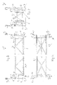
- Fig. 2 illustrates a device 1 for producing a flat surface 2 or plane (Fig.1) respectively.
- Surface made of a pourable building material 3, such as concrete, asphalt or the like, which solidifies after a certain dwell time in such a way that it can be loaded or driven on.
- the device 1 has a trigger bar 4, on the underside of which at least one, here two parallel trigger rails 5 are fixedly arranged (see also FIGS. 3 and 4).
- a support frame 6 is provided with struts, which has a triangular cross section.
- Motor-driven winches are arranged on the lateral ends of the take-off beam 4, by means of which the device 1 is moved transversely to its extension by winding up a pulling rope anchored at the end of the surface to be manufactured.
- the trigger bar 4 has a vibration wave (not shown) which runs parallel to the trigger rails 5 and which promotes the compaction of the building material 3 and produces a homogeneous structure.
- the trigger beam 4 is designed according to the invention at the lateral ends with a support device 7 with which it is connected in a height-adjustable manner is.
- the support device 7 in the device 1 shown consists of four support members 8, on which the trigger beam 4 is fastened in a height-adjustable manner.
- the trigger bar 4 is by an adjusting device 9, which will be described later, with the support device 7 and. the support members 8 connected.
- the adjustment device 9 has a support 10 connected to the trigger bar 4, to which a receiver 13 connected via a light beam 14 to a transmitter 11 of a measuring device 12 is fastened and which is guided through the support member 8.
- the measuring device 12 is, for example, a laser beam leveling device described briefly at the beginning, which is used, among other things, for the production of horizontal and inclined floors. Such laser beam leveling devices are described, for example, in CH-A-691708 and other patent literature.
- the rotating transmitter 11 generates a horizontal or inclined laser plane, according to which a receiver 13 can be aligned or aligned. are automatically adaptable in the present facility.
- a computer 15 and a control 16 connected to it are provided, which ensure that the receiver 13, which deviates from the emitted reference plane when the height of the support device 7 changes, makes a corresponding correction of the distance or the distance practically without delay via the adjustment device 9 between receiver 13 and support device 7 respectively.
- Support member / s 8 is initiated to keep the height of the trigger beam 4 constant. This means that the trigger beam 4 / trigger rail / s 5 resting on the building material 3 according to the measured or. leveled reference height 17 remain aligned. This principle allows precise processing of the building material 3 with less attention than is required for a leveled surface to be prepared.
- the device 1 according to the invention can be placed on a reinforcement and moved and for this purpose has runners 18 resting on the lower end of the support device 7 or on the underside of the support members 8, which allow the device 1 to slide even on an uneven surface, such as reinforcement nets , a formwork, lean concrete, grown underlay resp. grown soil or the like. Compacted base without affecting the manufacturing quality by making the device 1 easy to move.
- the receiver 13 which acts as a transmitter, and which is attached to the lateral ends of the trigger beam 4 and thus firmly connected to the trigger rail (s) 5 on the one hand and visually connected to the transmitter 11 of the laser beam leveling instrument 12, is also connected to a computer 15 which evaluates the deviations from the reference plane or the reference height 17 that occur during the movement of the device 1 and transmits corresponding control signals to the controller 16, which in turn corrects the distance between the trigger bar 4 or trigger rail (s) 5 by means of the support device 7 or the support members 8 adjustably connected to the adjustment device (s) 9.
- four support members 8 are provided as support devices 7, and each support member 8 is assigned a receiver 13, an adjusting device 9 and computer 15, as well as control 16, which acts on the support device 8.
- the rectangular arrangement of the support members according to FIG. 4 in plan view 8 allows automatic leveling or keeping the height constant the deduction bar 4 respectively.
- the trigger rail / s 5 in the production position, so that the latter during the movement of the device 1 on a reinforcement, one Formwork or other underlay a coplanar plane to the reference height respectively. form a plane parallel to the emitted reference plane.
- the runners 18 of the support device 7 are each aligned according to the direction of travel F and are arranged pivotably about an axis directed transversely to the direction of travel F for easier overcoming bumps or in order to be able to overcome differences in height on the support more easily.
- the runners 18 form part of the support members 8.
- two runners 8 can be assigned a runner 18 on a lateral end of the trigger beam 4 or a runner 18 can be assigned to each support member 8 on a lateral end of the trigger beam 8.
- the support members 8 in turn have a support leg 19 which interacts with an adjusting device 9 and is guided in the support 10 connected to the trigger beam 4.
- an electric motor 20 connected to the controller 16 is attached, which is preferably designed as a geared motor.
- an adjusting spindle 21 is fastened, which plunges into the upper end of the support leg 19, which is designed as a threaded sleeve 22.
- a tubular section of the support 10 connected to the trigger beam 4 forms a guide for the support leg 19.
- FIG. 5 shows an adjusting device 9 designed with a piston-cylinder unit 23 attached to the support 10.
- the support leg 19 is designed in the upper region as a guide piston 24, which is surrounded by a cylindrical part 25 of the support 10 is.
- the upper end of the guide piston 24 is coupled to a piston rod 25 which can be acted upon by a pressure medium from two sides in a cylinder 26 of the piston-cylinder unit 23. The drive of the piston rod 25, respectively.
- a directional control valve 27 which can be actuated by a control 16 and is connected to the piston-cylinder unit 23 via lines 32, 33, and by the receiver 13 of a measuring device 12 which is connected to a computer 15.
- the directional control valve 27 is on a pressure source, not shown, and a liquid reflux container connected. Should the base of the device 1 change in height on the movement path, for example in such a way that the support device 7 or.
- the receivers 13 of the measuring device 12 trigger a control signal which causes the control 16 to lower the trigger bar 4 or compensates for the height difference with respect to the reference height 17 which has arisen at the receiver 13 with respect to the transmitter 11, such that that the trigger rail / s 5 remain at a constant height.
- the device 1 To set up the device 1 on the building object, it is leveled to a or non-leveled, fixed storage space, for example reinforcement, formwork or parked as already mentioned.
- a measuring device 12 Outside the area to be manufactured 2 is by the transmitter 11 of a measuring device 12, for example by a rotating laser beam of a laser beam leveling device, one over the construction site extending reference plane is created, to which the receiver 13 to be aligned are.
- This work process that prepares the production work can be done with the help the height adjustability of the transmitter 11 attached to a tripod and the Adjustment device 9 are carried out with the one adjustable receiver 13 supporting support 10 is connected.
- the receiver 13 can be connected to the Support 10 releasably connected holding device can be adjustably attached. It is advantageous if the setting of the device 1 to the reference level in close to the reference height 17.
- the adjustment or setup work can be shortened by an alignment device 28 and facilitate when the aligner 28 is made from one on the trigger beam 4 releasably attached support member 29, on which a receiver 13th is attached.
- the alignment device 28 is used to provide the setup process the device 1 before manufacturing as well as aligning the device 1 according to the reference height 17 or the reference plane of the measuring device 12 during manufacturing.
- the alignment device 28 is set to the reference height 17 and then the receiver 13, which is adjustably attached to the support element 29, is adjusted to the emitted reference plane of the transmitter 11. Then the alignment device 28 is inserted with the support element 29 into a holder 30 provided on the support 10, so that the lower end of the support element 29 with the trigger plane or. is flush with the plane formed by the trigger rails 5 of the supporting beam 4 or adjoins this.
- the support element 29 is formed by a receiving device which is complementary to the holder 30, so that its lower edge always assumes the same position when the support element 29 is inserted in the holder 30.
Landscapes
- Engineering & Computer Science (AREA)
- Architecture (AREA)
- Civil Engineering (AREA)
- Structural Engineering (AREA)
- Physics & Mathematics (AREA)
- Optics & Photonics (AREA)
- Manufacturing & Machinery (AREA)
- Chemical & Material Sciences (AREA)
- Ceramic Engineering (AREA)
- Mechanical Engineering (AREA)
- Forms Removed On Construction Sites Or Auxiliary Members Thereof (AREA)
Priority Applications (2)
| Application Number | Priority Date | Filing Date | Title |
|---|---|---|---|
| EP02405523A EP1375751A1 (fr) | 2002-06-22 | 2002-06-22 | Dispositif pour réaliser des surfaces planes avec matériau de construction en vrac |
| CH00621/03A CH693638A5 (de) | 2002-06-22 | 2003-04-07 | Einrichtung zur Herstellung einer planen Fläche einer Schicht aus schüttfähigem Baustoff. |
Applications Claiming Priority (1)
| Application Number | Priority Date | Filing Date | Title |
|---|---|---|---|
| EP02405523A EP1375751A1 (fr) | 2002-06-22 | 2002-06-22 | Dispositif pour réaliser des surfaces planes avec matériau de construction en vrac |
Publications (1)
| Publication Number | Publication Date |
|---|---|
| EP1375751A1 true EP1375751A1 (fr) | 2004-01-02 |
Family
ID=29414857
Family Applications (1)
| Application Number | Title | Priority Date | Filing Date |
|---|---|---|---|
| EP02405523A Withdrawn EP1375751A1 (fr) | 2002-06-22 | 2002-06-22 | Dispositif pour réaliser des surfaces planes avec matériau de construction en vrac |
Country Status (2)
| Country | Link |
|---|---|
| EP (1) | EP1375751A1 (fr) |
| CH (1) | CH693638A5 (fr) |
Cited By (4)
| Publication number | Priority date | Publication date | Assignee | Title |
|---|---|---|---|---|
| DE102010037499A1 (de) * | 2010-09-13 | 2012-03-15 | Joachim Ezel | Vorrichtung zum Ebenziehen einer Füllmasse |
| EP2857585A1 (fr) | 2013-10-01 | 2015-04-08 | Wagner + Betontechnik AG | Dispositif de lissage d'une surface plane d'une couche constituée de matériaux de construction durcissables |
| CN109281458A (zh) * | 2017-07-21 | 2019-01-29 | 白明正 | 手持式震动拍浆整平器连接结构 |
| CN115110729A (zh) * | 2021-03-18 | 2022-09-27 | 广东博智林机器人有限公司 | 一种建筑材料铺贴基准装置及建筑材料铺贴机器人 |
Families Citing this family (2)
| Publication number | Priority date | Publication date | Assignee | Title |
|---|---|---|---|---|
| WO2007116044A1 (fr) * | 2006-04-10 | 2007-10-18 | Innenausbau Müller GmbH | Appareil et procédé de nivellement de remblai sec |
| AT514294B1 (de) * | 2013-05-14 | 2015-08-15 | Egon Döberl | Vorrichtung zur Nivellierung von Schüttungen und Baustoffen |
Citations (4)
| Publication number | Priority date | Publication date | Assignee | Title |
|---|---|---|---|---|
| EP0477024A1 (fr) * | 1990-09-20 | 1992-03-25 | Ray F. Haid | Poutre lisseuse ajustable et son moyen de réglage |
| US5567075A (en) * | 1995-07-07 | 1996-10-22 | Allen Engineering, Inc. | Offset screed system and quick connect mounting therefore |
| US6089787A (en) * | 1998-05-26 | 2000-07-18 | Allen Engineering Corp. | Transformable two-person floating screed with automatic grade control |
| CH691708A5 (de) | 1995-12-29 | 2001-09-14 | Ammann Lasertechnik | Laserstrahl-Nivelliergerät. |
-
2002
- 2002-06-22 EP EP02405523A patent/EP1375751A1/fr not_active Withdrawn
-
2003
- 2003-04-07 CH CH00621/03A patent/CH693638A5/de not_active IP Right Cessation
Patent Citations (4)
| Publication number | Priority date | Publication date | Assignee | Title |
|---|---|---|---|---|
| EP0477024A1 (fr) * | 1990-09-20 | 1992-03-25 | Ray F. Haid | Poutre lisseuse ajustable et son moyen de réglage |
| US5567075A (en) * | 1995-07-07 | 1996-10-22 | Allen Engineering, Inc. | Offset screed system and quick connect mounting therefore |
| CH691708A5 (de) | 1995-12-29 | 2001-09-14 | Ammann Lasertechnik | Laserstrahl-Nivelliergerät. |
| US6089787A (en) * | 1998-05-26 | 2000-07-18 | Allen Engineering Corp. | Transformable two-person floating screed with automatic grade control |
Cited By (6)
| Publication number | Priority date | Publication date | Assignee | Title |
|---|---|---|---|---|
| DE102010037499A1 (de) * | 2010-09-13 | 2012-03-15 | Joachim Ezel | Vorrichtung zum Ebenziehen einer Füllmasse |
| EP2857585A1 (fr) | 2013-10-01 | 2015-04-08 | Wagner + Betontechnik AG | Dispositif de lissage d'une surface plane d'une couche constituée de matériaux de construction durcissables |
| CN109281458A (zh) * | 2017-07-21 | 2019-01-29 | 白明正 | 手持式震动拍浆整平器连接结构 |
| CN109281458B (zh) * | 2017-07-21 | 2020-06-12 | 白明正 | 手持式震动拍浆整平器连接结构 |
| CN115110729A (zh) * | 2021-03-18 | 2022-09-27 | 广东博智林机器人有限公司 | 一种建筑材料铺贴基准装置及建筑材料铺贴机器人 |
| CN115110729B (zh) * | 2021-03-18 | 2024-03-22 | 广东博智林机器人有限公司 | 一种建筑材料铺贴基准装置及建筑材料铺贴机器人 |
Also Published As
| Publication number | Publication date |
|---|---|
| CH693638A5 (de) | 2003-11-28 |
Similar Documents
| Publication | Publication Date | Title |
|---|---|---|
| EP2927372B1 (fr) | Engin automobile et procédé de commande d'un engin automobile | |
| DE2131650A1 (de) | Strassenbaumaschine und Steuerungen dafuer | |
| CH669232A5 (de) | Vorrichtung zum einbringen von bewehrungsstaeben in eine fahrbahndecke aus beton. | |
| EP2287403A2 (fr) | Procédé de fabrication d'un revêtement routier, de préférence d'un revêtement routier en béton, et finisseuse de route | |
| EP2325393A1 (fr) | Procédé et finisseuse de route pour la fabrication d'un revêtement de route | |
| DE112016000713T5 (de) | Auto-Kalibrierung eines automatischen Nivelliersteuersystems in einer Arbeitsmaschine | |
| EP0495171B1 (fr) | Procédé pour régler l'épaisseur d'une couche à poser avec un finisseur | |
| EP1726740B1 (fr) | Méthode et appareil pour la préparation d'un lit de mortier humide | |
| DE2040605A1 (de) | Verfahren und Vorrichtung zur Herstellung einer eine strukturierte Oberflaeche aufweisenden stabilen Strassendecke | |
| CH693638A5 (de) | Einrichtung zur Herstellung einer planen Fläche einer Schicht aus schüttfähigem Baustoff. | |
| DE2109691A1 (de) | Vorrichtung zum Profilieren einer Oberflache | |
| DE2422942A1 (de) | Verfahren zur herstellung von eisenbahnoberbauten sowie fertigteile und vorrichtung zur durchfuehrung des verfahrens | |
| EP0240801B2 (fr) | Règle pour enduit | |
| DE4037981A1 (de) | Fertiger zum flaechenhaften einbau von beton o. dgl. als bodenschicht | |
| DE3036234C2 (de) | Vorrichtung zum Glätten einer Betonbelagsoberfläche | |
| DE2833311A1 (de) | Maschine zur herstellung eines strassenbelags | |
| DE1759744A1 (de) | Auf Raupen oder Raedern fahrender Strassendeckenfertiger | |
| EP2857585A1 (fr) | Dispositif de lissage d'une surface plane d'une couche constituée de matériaux de construction durcissables | |
| CH598429A5 (en) | Frame for applying concrete liner to excavated canal | |
| DE3117544A1 (de) | Duebelsetzen im betonstrassenbau | |
| WO2005116338A1 (fr) | Dispositif d'ajustage pour chassis de voie aiguillages | |
| DE2335157A1 (de) | Vorrichtung zum verlegen von pflastersteinen | |
| DE804535C (de) | Hubwagen fuer ortsbewegliche Kunststeinherstellung | |
| DE9217519U1 (de) | Vorrichtung zum Führen eines Fühlers o.dgl. Tastelements einer Straßenfertigungsmaschine | |
| DE2108846A1 (de) | Verfahren und Vorrichtung zum Legen kontinuierlicher Armierungen bei Betonstraßen decken |
Legal Events
| Date | Code | Title | Description |
|---|---|---|---|
| PUAI | Public reference made under article 153(3) epc to a published international application that has entered the european phase |
Free format text: ORIGINAL CODE: 0009012 |
|
| AK | Designated contracting states |
Kind code of ref document: A1 Designated state(s): AT BE CH CY DE DK ES FI FR GB GR IE IT LI LU MC NL PT SE TR |
|
| AX | Request for extension of the european patent |
Extension state: AL LT LV MK RO SI |
|
| 17P | Request for examination filed |
Effective date: 20040331 |
|
| AKX | Designation fees paid |
Designated state(s): AT BE CH CY DE DK ES FI FR GB GR IE IT LI LU MC NL PT SE TR |
|
| 17Q | First examination report despatched |
Effective date: 20071219 |
|
| STAA | Information on the status of an ep patent application or granted ep patent |
Free format text: STATUS: THE APPLICATION IS DEEMED TO BE WITHDRAWN |
|
| 18D | Application deemed to be withdrawn |
Effective date: 20080701 |