EP2928523B1 - Infusionspumpensystem und -verfahren - Google Patents
Infusionspumpensystem und -verfahren Download PDFInfo
- Publication number
- EP2928523B1 EP2928523B1 EP13862133.9A EP13862133A EP2928523B1 EP 2928523 B1 EP2928523 B1 EP 2928523B1 EP 13862133 A EP13862133 A EP 13862133A EP 2928523 B1 EP2928523 B1 EP 2928523B1
- Authority
- EP
- European Patent Office
- Prior art keywords
- drive system
- pump
- infusion pump
- piston rod
- electrically conductive
- Prior art date
- Legal status (The legal status is an assumption and is not a legal conclusion. Google has not performed a legal analysis and makes no representation as to the accuracy of the status listed.)
- Active
Links
Images


Classifications
-
- A—HUMAN NECESSITIES
- A61—MEDICAL OR VETERINARY SCIENCE; HYGIENE
- A61M—DEVICES FOR INTRODUCING MEDIA INTO, OR ONTO, THE BODY; DEVICES FOR TRANSDUCING BODY MEDIA OR FOR TAKING MEDIA FROM THE BODY; DEVICES FOR PRODUCING OR ENDING SLEEP OR STUPOR
- A61M5/00—Devices for bringing media into the body in a subcutaneous, intra-vascular or intramuscular way; Accessories therefor, e.g. filling or cleaning devices, arm-rests
- A61M5/14—Infusion devices, e.g. infusing by gravity; Blood infusion; Accessories therefor
- A61M5/142—Pressure infusion, e.g. using pumps
- A61M5/14244—Pressure infusion, e.g. using pumps adapted to be carried by the patient, e.g. portable on the body
-
- A—HUMAN NECESSITIES
- A61—MEDICAL OR VETERINARY SCIENCE; HYGIENE
- A61M—DEVICES FOR INTRODUCING MEDIA INTO, OR ONTO, THE BODY; DEVICES FOR TRANSDUCING BODY MEDIA OR FOR TAKING MEDIA FROM THE BODY; DEVICES FOR PRODUCING OR ENDING SLEEP OR STUPOR
- A61M5/00—Devices for bringing media into the body in a subcutaneous, intra-vascular or intramuscular way; Accessories therefor, e.g. filling or cleaning devices, arm-rests
- A61M5/14—Infusion devices, e.g. infusing by gravity; Blood infusion; Accessories therefor
- A61M5/1413—Modular systems comprising interconnecting elements
-
- A—HUMAN NECESSITIES
- A61—MEDICAL OR VETERINARY SCIENCE; HYGIENE
- A61M—DEVICES FOR INTRODUCING MEDIA INTO, OR ONTO, THE BODY; DEVICES FOR TRANSDUCING BODY MEDIA OR FOR TAKING MEDIA FROM THE BODY; DEVICES FOR PRODUCING OR ENDING SLEEP OR STUPOR
- A61M5/00—Devices for bringing media into the body in a subcutaneous, intra-vascular or intramuscular way; Accessories therefor, e.g. filling or cleaning devices, arm-rests
- A61M5/14—Infusion devices, e.g. infusing by gravity; Blood infusion; Accessories therefor
- A61M5/142—Pressure infusion, e.g. using pumps
- A61M5/145—Pressure infusion, e.g. using pumps using pressurised reservoirs, e.g. pressurised by means of pistons
- A61M5/1452—Pressure infusion, e.g. using pumps using pressurised reservoirs, e.g. pressurised by means of pistons pressurised by means of pistons
- A61M5/14566—Pressure infusion, e.g. using pumps using pressurised reservoirs, e.g. pressurised by means of pistons pressurised by means of pistons with a replaceable reservoir for receiving a piston rod of the pump
-
- A—HUMAN NECESSITIES
- A61—MEDICAL OR VETERINARY SCIENCE; HYGIENE
- A61M—DEVICES FOR INTRODUCING MEDIA INTO, OR ONTO, THE BODY; DEVICES FOR TRANSDUCING BODY MEDIA OR FOR TAKING MEDIA FROM THE BODY; DEVICES FOR PRODUCING OR ENDING SLEEP OR STUPOR
- A61M5/00—Devices for bringing media into the body in a subcutaneous, intra-vascular or intramuscular way; Accessories therefor, e.g. filling or cleaning devices, arm-rests
- A61M5/14—Infusion devices, e.g. infusing by gravity; Blood infusion; Accessories therefor
- A61M5/168—Means for controlling media flow to the body or for metering media to the body, e.g. drip meters, counters ; Monitoring media flow to the body
- A61M5/16831—Monitoring, detecting, signalling or eliminating infusion flow anomalies
-
- A—HUMAN NECESSITIES
- A61—MEDICAL OR VETERINARY SCIENCE; HYGIENE
- A61M—DEVICES FOR INTRODUCING MEDIA INTO, OR ONTO, THE BODY; DEVICES FOR TRANSDUCING BODY MEDIA OR FOR TAKING MEDIA FROM THE BODY; DEVICES FOR PRODUCING OR ENDING SLEEP OR STUPOR
- A61M5/00—Devices for bringing media into the body in a subcutaneous, intra-vascular or intramuscular way; Accessories therefor, e.g. filling or cleaning devices, arm-rests
- A61M5/14—Infusion devices, e.g. infusing by gravity; Blood infusion; Accessories therefor
- A61M5/168—Means for controlling media flow to the body or for metering media to the body, e.g. drip meters, counters ; Monitoring media flow to the body
- A61M5/172—Means for controlling media flow to the body or for metering media to the body, e.g. drip meters, counters ; Monitoring media flow to the body electrical or electronic
-
- A—HUMAN NECESSITIES
- A61—MEDICAL OR VETERINARY SCIENCE; HYGIENE
- A61M—DEVICES FOR INTRODUCING MEDIA INTO, OR ONTO, THE BODY; DEVICES FOR TRANSDUCING BODY MEDIA OR FOR TAKING MEDIA FROM THE BODY; DEVICES FOR PRODUCING OR ENDING SLEEP OR STUPOR
- A61M5/00—Devices for bringing media into the body in a subcutaneous, intra-vascular or intramuscular way; Accessories therefor, e.g. filling or cleaning devices, arm-rests
- A61M5/14—Infusion devices, e.g. infusing by gravity; Blood infusion; Accessories therefor
- A61M5/142—Pressure infusion, e.g. using pumps
- A61M2005/14208—Pressure infusion, e.g. using pumps with a programmable infusion control system, characterised by the infusion program
-
- A—HUMAN NECESSITIES
- A61—MEDICAL OR VETERINARY SCIENCE; HYGIENE
- A61M—DEVICES FOR INTRODUCING MEDIA INTO, OR ONTO, THE BODY; DEVICES FOR TRANSDUCING BODY MEDIA OR FOR TAKING MEDIA FROM THE BODY; DEVICES FOR PRODUCING OR ENDING SLEEP OR STUPOR
- A61M5/00—Devices for bringing media into the body in a subcutaneous, intra-vascular or intramuscular way; Accessories therefor, e.g. filling or cleaning devices, arm-rests
- A61M5/14—Infusion devices, e.g. infusing by gravity; Blood infusion; Accessories therefor
- A61M5/142—Pressure infusion, e.g. using pumps
- A61M5/14244—Pressure infusion, e.g. using pumps adapted to be carried by the patient, e.g. portable on the body
- A61M2005/14268—Pressure infusion, e.g. using pumps adapted to be carried by the patient, e.g. portable on the body with a reusable and a disposable component
-
- A—HUMAN NECESSITIES
- A61—MEDICAL OR VETERINARY SCIENCE; HYGIENE
- A61M—DEVICES FOR INTRODUCING MEDIA INTO, OR ONTO, THE BODY; DEVICES FOR TRANSDUCING BODY MEDIA OR FOR TAKING MEDIA FROM THE BODY; DEVICES FOR PRODUCING OR ENDING SLEEP OR STUPOR
- A61M5/00—Devices for bringing media into the body in a subcutaneous, intra-vascular or intramuscular way; Accessories therefor, e.g. filling or cleaning devices, arm-rests
- A61M5/178—Syringes
- A61M5/31—Details
- A61M5/315—Pistons; Piston-rods; Guiding, blocking or restricting the movement of the rod or piston; Appliances on the rod for facilitating dosing ; Dosing mechanisms
- A61M5/31511—Piston or piston-rod constructions, e.g. connection of piston with piston-rod
- A61M2005/31518—Piston or piston-rod constructions, e.g. connection of piston with piston-rod designed to reduce the overall size of an injection device, e.g. using flexible or pivotally connected chain-like rod members
-
- A—HUMAN NECESSITIES
- A61—MEDICAL OR VETERINARY SCIENCE; HYGIENE
- A61M—DEVICES FOR INTRODUCING MEDIA INTO, OR ONTO, THE BODY; DEVICES FOR TRANSDUCING BODY MEDIA OR FOR TAKING MEDIA FROM THE BODY; DEVICES FOR PRODUCING OR ENDING SLEEP OR STUPOR
- A61M2205/00—General characteristics of the apparatus
- A61M2205/14—Detection of the presence or absence of a tube, a connector or a container in an apparatus
-
- A—HUMAN NECESSITIES
- A61—MEDICAL OR VETERINARY SCIENCE; HYGIENE
- A61M—DEVICES FOR INTRODUCING MEDIA INTO, OR ONTO, THE BODY; DEVICES FOR TRANSDUCING BODY MEDIA OR FOR TAKING MEDIA FROM THE BODY; DEVICES FOR PRODUCING OR ENDING SLEEP OR STUPOR
- A61M2205/00—General characteristics of the apparatus
- A61M2205/18—General characteristics of the apparatus with alarm
-
- A—HUMAN NECESSITIES
- A61—MEDICAL OR VETERINARY SCIENCE; HYGIENE
- A61M—DEVICES FOR INTRODUCING MEDIA INTO, OR ONTO, THE BODY; DEVICES FOR TRANSDUCING BODY MEDIA OR FOR TAKING MEDIA FROM THE BODY; DEVICES FOR PRODUCING OR ENDING SLEEP OR STUPOR
- A61M2205/00—General characteristics of the apparatus
- A61M2205/33—Controlling, regulating or measuring
-
- A—HUMAN NECESSITIES
- A61—MEDICAL OR VETERINARY SCIENCE; HYGIENE
- A61M—DEVICES FOR INTRODUCING MEDIA INTO, OR ONTO, THE BODY; DEVICES FOR TRANSDUCING BODY MEDIA OR FOR TAKING MEDIA FROM THE BODY; DEVICES FOR PRODUCING OR ENDING SLEEP OR STUPOR
- A61M2205/00—General characteristics of the apparatus
- A61M2205/50—General characteristics of the apparatus with microprocessors or computers
- A61M2205/502—User interfaces, e.g. screens or keyboards
-
- A—HUMAN NECESSITIES
- A61—MEDICAL OR VETERINARY SCIENCE; HYGIENE
- A61M—DEVICES FOR INTRODUCING MEDIA INTO, OR ONTO, THE BODY; DEVICES FOR TRANSDUCING BODY MEDIA OR FOR TAKING MEDIA FROM THE BODY; DEVICES FOR PRODUCING OR ENDING SLEEP OR STUPOR
- A61M2205/00—General characteristics of the apparatus
- A61M2205/58—Means for facilitating use, e.g. by people with impaired vision
- A61M2205/581—Means for facilitating use, e.g. by people with impaired vision by audible feedback
-
- A—HUMAN NECESSITIES
- A61—MEDICAL OR VETERINARY SCIENCE; HYGIENE
- A61M—DEVICES FOR INTRODUCING MEDIA INTO, OR ONTO, THE BODY; DEVICES FOR TRANSDUCING BODY MEDIA OR FOR TAKING MEDIA FROM THE BODY; DEVICES FOR PRODUCING OR ENDING SLEEP OR STUPOR
- A61M2205/00—General characteristics of the apparatus
- A61M2205/58—Means for facilitating use, e.g. by people with impaired vision
- A61M2205/582—Means for facilitating use, e.g. by people with impaired vision by tactile feedback
-
- A—HUMAN NECESSITIES
- A61—MEDICAL OR VETERINARY SCIENCE; HYGIENE
- A61M—DEVICES FOR INTRODUCING MEDIA INTO, OR ONTO, THE BODY; DEVICES FOR TRANSDUCING BODY MEDIA OR FOR TAKING MEDIA FROM THE BODY; DEVICES FOR PRODUCING OR ENDING SLEEP OR STUPOR
- A61M2205/00—General characteristics of the apparatus
- A61M2205/58—Means for facilitating use, e.g. by people with impaired vision
- A61M2205/583—Means for facilitating use, e.g. by people with impaired vision by visual feedback
-
- A—HUMAN NECESSITIES
- A61—MEDICAL OR VETERINARY SCIENCE; HYGIENE
- A61M—DEVICES FOR INTRODUCING MEDIA INTO, OR ONTO, THE BODY; DEVICES FOR TRANSDUCING BODY MEDIA OR FOR TAKING MEDIA FROM THE BODY; DEVICES FOR PRODUCING OR ENDING SLEEP OR STUPOR
- A61M2205/00—General characteristics of the apparatus
- A61M2205/82—Internal energy supply devices
- A61M2205/8206—Internal energy supply devices battery-operated
Definitions
- This document relates to an infusion pump system, such as a portable infusion pump system for dispensing a medicine.
- a medical infusion pump device may be used to deliver a medicine to a patient as part of a medical treatment.
- the medicine that is delivered by the infusion pump device can depend on the condition of the patient and the desired treatment plan.
- infusion pump devices have been used to deliver insulin to the vasculature of diabetes patients so as to regulate blood-glucose levels.
- Infusion pump devices often need to deliver medicine in accurately controlled dosages. Over-dosages and under-dosages of medicine can be detrimental to patients.
- an infusion pump device that delivers an over-dosage or under-dosage of insulin to a diabetes patient can significantly affect the blood-glucose level of the patient.
- an infusion pump to deliver an accurately controlled dosage can be negatively affected if the pump device has sustained damage from a physical impact. Damage to an infusion pump device may result, for example, from dropping the infusion pump device onto a floor or other hard surface in a manner that could damage or otherwise hinder the drive system of the pump device.
- US 2010/0094251 describes an infusion pump system that can be configured to modify alarm limit parameters as the user's insulin load increases or decreases. Moreover, in particular embodiments, the infusion pump system can be configured to provide a "missed bolus" or "missed meal” alarm in response to the user's blood glucose characteristics, the user's insulin load information, or the like.
- a first aspect of the present invention relates a medical infusion pump system as defined in independent claim 1, and optional dependent claims.
- a second aspect of the present invention relates to method of controlling the said medical infusion pump system as defined in independent claim 12, and optional dependent claims.
- An infusion pump system as claimed is equipped with a drive system detection system configured to detect when one or more components of the drive system are damaged or inoperable.
- the drive system detector can sense when an impact (or other event) has occurred to the drive system of the pump device, which thereby enables the infusion pump system to initiate approp1iate patient safety countermeasures.
- Appropriate patient safety counter measures can include, for example, disablement of medicine delivery by the pump device, emitting an alarm to the user, and prompting the user to perform a number of remedial action.
- the pump device is a single-use disposable component and the pump controller is a reusable component
- the drive system detector can be located in the pump device.
- Such a configuration can be useful because a significant impact imparted to the pump device component prior to connection (e.g., via a wired or wireless connection) with the controller component can be detected by the pump device component and identified by the controller component when the pump device component and controller component are initially connected.
- the infusion pump system can initiate appropriate patient safety countermeasures prior to the patient's use of the system. If no such prior impact occurred, the system can be used in the normal fashion, and the drive system detector can continue to monitor for impacts above the threshold level while the pump device component and controller component are connected together. If such an impact is detected by the drive system detector while the pump device component and controller component are connected together, the infusion pump system can respond at that time by initiating appropriate patient safety countermeasures.
- the portable medical infusion pump system may include a pump device including a pump housing that defines a space to receive a medicine, a drive system positioned in the pump housing to dispense the medicine from the pump device when the medicine is received in the space of the pump housing.
- the pump housing may house at least one electrically conductive element of a drive system detector, which optionally, is mounted to a component of the drive system.
- the system may also include a controller device removably attachable to the pump housing so as to electrically connect with the pump device.
- the controller device may house control circuitry configured to communicate with the drive system positioned in the pump housing to control dispensation of the medicine from the pump device.
- the control circuitry of the controller device can be configured to disable the pump drive system in response to the drive system detector indicating damage to one or more components of the drive system.
- Embodiments of the medical infusion pump system may include a portable housing defining a space to receive a medicine, and a pump drive system to dispense medicine from the portable housing when the medicine is received in the space.
- the system may also include control circuitry that electrically communicates with the pump drive system to control dispensation of the medicine from the portable housing when the medicine is received in the space.
- the system may further includes a drive system detector comprising at least one electrically conductive element coupled to a component of the pump drive system.
- the control circuitry may disable the pump drive system in response to the drive system detector indicating damage to one or more components of the drive system.
- a method of controlling a portable infusion pump system may include sensing that a drive system of a portable infusion pump system is damaged via a drive system detector including an electrically conductive element of that is coupled to a component of the drive system in the portable infusion pump system. The method may further include, in response to the sensing that the drive system detector indicates said drive system is damaged, disabling the pump drive system housed in the portable infusion pump system.
- some embodiments of the infusion pump system may be configured to detect when one or more components of a pump drive system have sustained an impact that could potentially damage the system or otherwise cause over- dosage or under-dosage of medicine to the user.
- some embodiments of the infusion pump system may initiate user safety countermeasures upon detection that the system has sustained an impact above a threshold level.
- certain embodiments of an infusion pump system may prevent use of a damaged system that may have some potential for delivery of an improper medicine dosage if used.
- some embodiment of the infusion pump system may include drive system detector located in the single use pump device thereby providing passive user safety protection.
- the infusion pump system may be configured to be portable, wearable, and (in some circumstances) concealable.
- a user can conveniently wear the infusion pump system on the user's skin under clothing or can carry the pump system in the user's pocket (or other portable location) while receiving the medicine dispensed from the pump device.
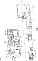
- an infusion pump system 10 can include a pump device 100 and a controller device 200 that communicates with the pump device 100.
- the pump device 100 in this embodiment includes a housing structure 110 that defines a cavity 116 in which a fluid cartridge 120 can be received.
- the pump device 100 also can include a cap device 130 to retain the fluid cartridge 120 in the cavity 116 of the housing structure 110.
- the pump device 100 can include a drive system that advances a plunger 125 in the fluid cartridge 120 so as to dispense fluid therefrom.
- some embodiments of the pump device 100 can include an internal drive system detector 380.
- the drive system detector 380 comprises an electrically conductive element that is coupled to components of the drive system.
- the drive system detector 380 includes an electrically conductive element coupled to a piston rod of the drive system and a software component stored in the control circuitry (of the controller device 200 in this embodiment) that is configured to periodically monitor the electrically conductive element.
- the drive system detector 380 can be configured to sense a change in impedance across the electrically conductive element when the pump device 100 has received an impact force that results in damage to the drive system 300 ( FIG. 7 ).
- damage to the drive system may include where one or more components of the drive system 300 have sustained a partial fracture, complete breakage, or otherwise sustained damage that may affect the structural integrity of one or more components of the drive system 300.
- the pump device 100 may potentially malfunction or otherwise cause over-dosage or under-dosage of medicine to the user. For example, in some situations, a user of the pump device 100 may expose the pump device 100 to an impact force.
- the drive system 300 of the pump device 100 may be rendered inoperable for safe and accurate dispensation of medicine, and as such, some or all of the remaining medicine (e.g., in medicine cartridge 120) contained within pump device 100 may not be properly dispensed.
- an impact that may cause damage to the drive system 300 of the pump device 100 that can be detected using a drive system detector 380 that monitors at least one electrically conductive element coupled to one or more components of the drive system 300.
- Such an impact may occur, for example, by dropping the pump device 100 onto a floor or other hard surface.
- the drive system detector 380 can be in electrical communication with a circuit housed in the controller device 200. In such a case, if the drive system detector 380 previously detected damage to one or more components of the drive system 300, the infusion pump system 10 can be configured to initiate appropriate user safety countermeasures. If no such damage to the drive system was detected, the pump system 10 can proceed with normal operations. During normal operations, if the drive system detector 380 then detects damage to one or more components of the drive system 300, the pump system 10 can respond by initiating appropriate user safety countermeasures.
- the controller device 200 communicates with the pump device 100 to control the operation of the drive system.
- the user can (in some embodiments) conveniently wear the infusion pump system 10 on the user's skin under clothing, in a pouch clipped at the waist (e.g., similar to a cell phone pouch), or in the user's pocket while receiving the fluid dispensed from the pump device 100.
- the controller device 200 may be configured as a reusable component that provides electronics and a user interface to control the operation of the pump device 100.
- the pump device 100 can be a disposable component that is disposed of after a single use.
- the pump device 100 can be a "one time use" component that is thrown away after the fluid cartridge 120 therein is exhausted. Thereafter, the user can removably attach a new pump device 100' (having a new medicine cartridge 120') to the reusable controller device 200 for the dispensation of fluid from a new fluid cartridge 120'. Accordingly, the user is permitted to reuse the controller device 200 (which may include complex or valuable electronics, as well as a rechargeable battery) while disposing of the relatively low-cost pump device 100 after each use.
- a pump system 10 can provide enhanced user safety as a new pump device 100' (and drive system therein) is employed with each new fluid cartridge 120'.
- the pump device 100 is configured to removably attach to the controller device 200 in a manner that provides a secure fitting, an overall compact size, and a reliable electrical connection that is resistant to water migration.
- the controller device 200 can include a housing 210 having a number of features that mate with complementary features of the pump housing 110. In such circumstances, the controller device 200 can removably attach with the pump device 100 in a generally side-by-side configuration.
- the compact size permits the infusion pump system 10 to be discrete and portable (as described below in connection with FIG. 3 ).
- at least one of the pump device 100 or the controller device 200 can include a release member that facilitates an easy-to-use detachment and replacement process.
- the pump system 10 can be a medical infusion pump system that is configured to controllably dispense a medicine from the cartridge 120.
- the fluid cartridge 120 can contain a medicine 126 to be infused into the tissue or vasculature of a targeted individual, such as a human or animal patient.
- the pump device 100 can be adapted to receive a medicine cartridge 120 in the form of a carpule that is preloaded with insulin or another medicine for use in the treatment of Diabetes (e.g., Byetta ® , Symlin ® , or others).
- a medicine cartridge 120 may be supplied, for example, by Eli Lilly and Co. of Indianapolis, IN.
- the fluid cartridge 120 may have other configurations.
- the fluid cartridge 120 may comprise a reservoir that is integral with the pump housing structure 110 (e.g., the fluid cartridge 120 can be defined by one or more walls of the pump housing structure 110 that surround a plunger to define a reservoir in which the medicine is injected or otherwise received).
- the pump device 100 can include one or more structures that interfere with the removal of the medicine cartridge 120 after the medicine cartridge 120 is inserted into the cavity 116.
- the pump housing structure 110 can include one or more retainer wings (not shown in FIG. 1 ) that at least partially extend into the cavity 116 to engage a portion of the medicine cartridge 120 when the medicine cartridge 120 is installed therein.
- the retainer wings can interfere with attempts to remove the medicine cartridge 120 from the pump device 100, thus ensuring that the pump device 100 will be discarded along with the medicine cartridge 120 after the medicine cartridge 120 is emptied, expired, or otherwise exhausted.
- the cap device 130 can be configured to irreversibly attach to the pump body 110 so as to cover the opening of the cavity 116.
- a head structure of the cap device 130 can be configured to turn so as to threadably engage the cap device 130 with a mating structure along an inner wall of the cavity 116, but the head structure may prevent the cap device from turning in the reverse direction so as to disengage the threads.
- the pump device 100 can operate in a tamper-resistant and safe manner because the pump device 100 can be designed with a predetermined life expectancy (e.g., the "one-time-use" feature in which the pump device is discarded after the medicine cartridge 120 is emptied, expired, or otherwise exhausted).
- the controller device 200 can be removably attached to the pump device 100 so that the two components are mechanically mounted to one another in a fixed relationship. Such a mechanical mounting can form an electrical connection between the removable controller device 200 and the pump device 100.
- the controller device 200 can be in electrical communication with a portion of a drive system (not shown in FIG. 1 ) of the pump device 100.
- the pump device 100 can include a drive system that causes controlled dispensation of the medicine or other fluid from the cartridge 120.
- the drive system incrementally advances a piston rod (not shown in FIG. 1 ) longitudinally into the cartridge 120 so that the fluid is forced out of an output end 122.
- a septum 121 FIG.
- the controller device 200 communicates electronic control signals via a hardwire-connection (e.g., electrical contacts or the like) to the drive system or other components of the pump device 100.
- the drive system of the pump device 100 causes medicine to incrementally dispense from the medicine cartridge 120.
- Power signals such as signals from the rechargeable battery 245 (refer to FIG. 6 ) of the controller device 200 and from the power source 310 (refer to FIG. 7 ) of the pump device 100 may also be passed between the controller device 200 and the pump device 100.
- the pump device 100 can include an electrical connector 118 (e.g., having conductive pads, pins, and the like) that is exposed to the controller device 200 and that mates with a complementary electrical connector (refer to connector 218 in FIG. 2 ) on the adjacent face of the controller device 200.
- the electrical connectors 118 and 218 provide the electrical communication between the control circuitry (refer, for example, to FIG. 6 ) housed in the controller device 200 and at least a portion of the drive system or other components of the pump device 100.
- the electrical connectors 118 and 218 can permit the transmission of electrical control signals to the pump device 100 and the reception of feedback signals (e.g., sensor signals) from particular components within the pump device 100.
- the electrical connectors 118 and 218 may similarly facilitate transmission of one or more power signals from the rechargeable battery pack 245 to the pump device 100, where the signals may be used to provide power to components of the pump device 100, or to transmit one or more power signals from the power source 310 to the controller device, where the signals may be used to charge the rechargeable battery 245 or to power components of the controller device 200.
- the controller device 200 can include a user interface 220 that permits a user to monitor the operation of the pump device 100.
- the user interface 220 can include a display device 222 and one or more user-selectable buttons (e.g., several buttons 224 are shown in the embodiment of FIG. 1 ).
- the display device 222 can include an active area in which numerals, text, symbols, images, or a combination thereof can be displayed.
- the display device 222 can be used to communicate a number of settings or menu options for the infusion pump system 10.
- the user may press one or more of the buttons to shuffle through a number of menus or program screens that show particular settings and data (e.g., review data that shows the medicine dispensing rate, the total amount of medicine dispensed in a given time period, the amount of medicine scheduled to be dispensed at a particular time or date, the approximate amount of medicine remaining in the cartridge 120, or the like).
- the user can adjust the settings or otherwise program the controller device 200 by pressing one or more buttons of the user interface 220.
- the user may press one or more of the buttons to change the dispensation rate of insulin or to request that a bolus of insulin be dispensed immediately or at a scheduled, later time.
- the display device 222 may also be used to communicate information regarding remaining battery life.
- the user when the controller device 200 is connected to the pump device 100, the user can be provided with the opportunity to readily monitor the infusion pump operation by simply viewing the user interface 220 of the controller device 200 connected to the pump device 100.
- Such monitoring capabilities may provide comfort to a user who may have urgent questions about the current operation of the pump device 100.
- the user can readily operate the user interface 220 of the controller device 200, which is removably attached to the pump device 100, without the requirement of locating and operating a separate monitoring module.
- the controller device 200 can also be equipped with an inspection light device 230.
- the inspection light device 230 can provide the user with a tool to illuminate and inspect a targeted location.
- the inspection light device 230 can be directed at the infusion site on the user's skin to verify that the infusion set is properly embedded, or the inspection light device 230 can be directed at the pump device 100 to illuminate the cavity 116 or other areas.
- the inspection light device 230 can also be used to notify the user to an alert condition of the pump system 10. For example, as described further in reference to FIG. 12 below, the inspection light device 230 can be activated when the drive system detector 380 has detected damage to one or more components of the drive system 300. An activation of the inspection light device 230 can thereby provide a visual notification (as an alternative to, or in addition to, the visual notification provided on the display device 222) to the user that attention to the pump system 10 is warranted.
- the controller device 200 can be removably attached to the pump device 100 in a side-by-side arrangement.
- the pump device 100 may be moved in a longitudinal direction (e.g., refer to direction 219 in FIG. 4 ) toward the controller device 200 until the complementary features connect and secure the separate components in the side-by-side arrangement.
- the controller device 200 can include a controller housing structure 210 having a number of features that are configured to mate with complementary features of the pump housing structure 110 so as to form a releasable mechanical connection.
- the pump housing structure 110 can include a barrel 111 that mates with a complementary barrel channel 211 of the controller housing 210.
- the pump device 100 and the controller device 200 can be mounted to one another so that the assembled system 10 is resistant to water migration both into the pump housing structure 110 and the controller housing structure 210.
- Such a configuration can also provide water-resistant protection for the electrical connection between the pump device 100 and the controller device 200.
- the sensitive internal components in the controller device 200 and the pump device 100 can be reliably protected from water migration if the user encounters water (e.g., rain, incidental splashing, and the like) while using the pump system 10.
- the infusion pump system 10 can be configured to be portable and can be wearable and concealable.
- a user can conveniently wear the infusion pump system 10 on the user's skin (e.g., skin adhesive) underneath the user's clothing or carry the pump device 100 in the user's pocket (or other portable location) while receiving the medicine dispensed from the pump device 100.
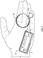
- the pump system 10 is shown in FIG. 3 as being held in a user's hand 5 so as to illustrate an exemplary size of the system 10 in accordance with some embodiments.
- the infusion pump system 10 is compact so that the user can wear the portable infusion pump system 10 (e.g., in the user's pocket, connected to a belt clip, adhered to the user's skin, or the like) without the need for carrying and operating a separate module.
- the cap device 130 of the pump device 100 can be configured to mate with an infusion set 146.
- the infusion set 146 can be a tubing system that connects the infusion pump system 10 to the tissue or vasculature of the user (e.g., to deliver medicine into the tissue or vasculature under the user's skin).
- the infusion set 146 can include a flexible tube 147 that extends from the pump device 100 to a subcutaneous cannula 149 that may be retained by a skin adhesive patch (not shown) that secures the subcutaneous cannula 149 to the infusion site.
- the skin adhesive patch can retain the infusion cannula 149 in fluid communication with the tissue or vasculature of the user so that the medicine dispensed through the tube 147 passes through the cannula 149 and into the user's body.
- the cap device 130 can provide fluid communication between the output end 122 ( FIG. 1 ) of the medicine cartridge 120 and the tube 147 of the infusion set 146.
- the infusion pump system 10 can be pocket-sized so that the pump device 100 and controller device 200 can be worn in the user's pocket or in another portion of the user's clothing.
- the user may desire to wear the pump system 10 in a more discrete manner. Accordingly, the user can pass the tube 147 from the pocket, under the user's clothing, and to the infusion site where the adhesive patch can be positioned.
- the pump system 10 can be used to deliver medicine to the tissues or vasculature of the user in a portable, concealable, and discrete manner.
- the infusion pump system 10 can be configured to adhere to the user's skin directly at the location in which the skin is penetrated for medicine infusion.
- a rear surface 102 ( FIG. 2 ) of the pump device 100 can include a skin adhesive patch so that the pump device 100 can be physically adhered to the skin of the user at a particular location.
- the cap device 130 can have a configuration in which medicine passes directly from the cap device 130 into an infusion cannula 149 that is penetrated into the user's skin.
- the user can temporarily detach the controller device 200 (while the pump device 100 remains adhered to the skin) so as to view and interact with the user interface 220.
- the infusion pump system 10 can be operated such that the pump device 100 is a disposable, non-reusable component while the controller device 200 is a reusable component.
- the pump device 100 may be configured as a "one-time-use" device that is discarded after the medicine cartridge is emptied, expired, or otherwise exhausted.
- the pump device 100 can be designed to have an expected operational life of about 1 day to about 30 days, about 1 day to about 20 days, about 1 to about 14 days, or about 1 day to about 7 days-depending on the volume of medicine in the cartridge 120, the dispensation patterns that are selected for the individual user, and other factors.
- a medicine cartridge 120 containing insulin can have an expected usage life of about 7 days after the cartridge is removed from a refrigerated state and the septum 121 is punctured.
- the dispensation pattern selected by the user can cause the insulin to be emptied from the medicine cartridge 120 before the 7-day period. If the insulin is not emptied from the medicine cartridge 120 after the 7-day period, the remaining insulin can become expired sometime thereafter. In either case, the pump device 100 and the medicine cartridge 120 therein can be collectively discarded after exhaustion of the medicine cartridge 120 (e.g., after being emptied, expired, or otherwise not available for use).
- the controller device 200 may be reused with subsequent new pump devices 100' and new medicine cartridges 120'.
- the control circuitry, the user interface components, the rechargeable battery pack 245, and other components that may have relatively higher manufacturing costs can be reused over a longer period of time.
- the controller device 200 can be designed to have an expected operational life of about 1 year to about 7 years, about 2 years to about 6 years, or about 3 years to about 5 years-depending on a number of factors including the usage conditions for the individual user.
- the user can be permitted to reuse the controller device 200 (which can include complex or valuable electronics, and a rechargeable battery pack) while disposing of the relatively low-cost pump device 100 after each use.
- Such a pump system 10 can provide enhanced user safety as a new pump device 100' (and drive system therein) is employed with each new medicine cartridge 120'.
- the same controller device 200 can be reused with a new pump device 100' having a new medicine cartridge 120' retained therein, and the previously used pump device 100, including the exhausted medicine cartridge, can be discarded in a discard bin 20.
- the new pump device 100' ( FIG. 4 ) can have a similar appearance, form factor, and operation as the previously used pump device 100, and thus the new pump device 100' can be readily attached to the controller device 200 for controlled dispensation of medicine from the new medicine cartridge 120'.
- the user can prepare the new pump device 100' for use with the controller device 200.
- the user may insert the new medicine cartridge 120' in the cavity 116 of the new pump device 100' and then join the cap device 130 to the pump housing to retain the new medicine cartridge 120' therein (refer, for example, to FIG. 1 ).
- the tubing 147 of the infusion set 146 is not shown in FIG. 4 , it should be understood that the tubing 147 can be attached to the cap device 130 prior to the cap device 130 being joined with the housing 110.
- a new infusion set 146 can be connected to the cap device 130 so that the tubing 147 can be primed (e.g., a selected function of the pump device 100 controlled by the controller device 200) before attaching the cannula's adhesive patch to the user's skin.
- the new medicine cartridge 120' may be filled with medicine such that the plunger 125 is not viewable through the barrel 111.
- the new pump device 100' can be removably attached to the controller device 200 to assemble into the infusion pump system 10 for delivery of medicine to the user.
- the guided motion in the longitudinal direction 219 provides the user with a convenient "one-movement" process to attach the pump device 100' and the controller device 200.
- the user can readily slide the pump device 100' and the controller device 200 toward one another in a single movement (e.g., in the longitudinal direction 219) that causes both a physical connection and an electrical connection.
- the infusion pump system 10 can permit users to readily join the pump device 100' and the controller device 200 without compound or otherwise difficult hand movements-a feature that can be particularly beneficial to child users or to elderly users.
- the controller device 200 houses a number of components that can be reused with a series of successive pump devices 100.
- the controller device 200 can include controller circuitry 240 and a rechargeable battery pack 245, each arranged in the controller housing 210.
- rechargeable battery pack 245 may provide electrical energy to components of controller circuitry 240, other components of the controller device (e.g., a display device 222 and other user interface components, sensors, or the like), or to components of the pump device 100.
- Controller circuitry 240 may be configured to communicate control or power signals to the drive system of the pump device 100, or to receive power or feedback signals from the pump device 100.
- the user interface 220 of the controller device 200 can include input components and/or output components that are electrically connected to the controller circuitry 240.
- the user interface 220 can include the display device 222 having an active area that outputs information to a user and buttons 224 that the user can use to provide input.
- the display device 222 can be used to communicate a number of settings or menu options for the infusion pump system 10.
- the controller circuitry 240 can receive input commands from a user's button selections and thereby cause the display device 222 to output a number of menus or program screens that show particular settings and data (e.g., review data that shows the medicine dispensing rate, the total amount of medicine dispensed in a given time period, the amount of medicine scheduled to be dispensed at a particular time or date, the approximate amount of medicine remaining the cartridge 120, the amount of battery life remaining, or the like).
- the controller circuitry 240 can be programmable to cause the controller circuitry 240 to change any one of a number of settings for the infusion pump system 10. For example, the user may provide one or more instructions to adjust a number of settings for the operation of the infusion pump system 10. Such settings may be stored in one or more memory devices arranged in the controller circuitry 240.
- the infusion pump system 10 can be equipped with the inspection light device 230 to conveniently aid in visual inspection processes.
- visual inspection and possible change of the infusion set 146 may be required in less than optimal conditions, including low-light conditions.
- visual inspection of the pump housing cavity 116 (and the medicine cartridge 120 therein) may be required in low-light conditions.
- the user interface 220 of the controller device 200 can include an illuminated display screen 222 to facilitate the user's view of the display screen 222, but the inspection light device 230 provides a dedicated light source for illuminating targeted sites external to the controller device 200, for providing an alert notification, or a combination thereof.
- the inspection light device 230 can include one or more user triggered light sources that are positioned to direct illumination at targeted objects outside of the pump system 10 or at components of the pump device 100.
- the light source is arranged on the controller device 200.
- Such an arrangement provides close proximity to the control circuitry 240 housed in the controller device 200, thereby permitting the light source of the inspection light device 230 to be electrically connected to the control circuitry.
- the inspection light device 230 can also be used to provide a visual notification to the user in the event of an alert or alarm condition.
- the inspection light device 230 can be activated in response to detection by the drive system detector 380 of damage to one or more components of the drive system 300 (e.g., where pump system 10 sustains an impact force), which may cause a malfunction of the pump system 10.
- the controller circuitry 240 can include a cable connector (e.g., a USB connection port or another data cable port) that is accessible on an external portion of the controller housing 210.
- a cable can be connected to the controller circuitry 240 to upload data or program settings to the controller circuitry or to download data from the controller circuitry.
- data can also provide recharging power.
- the pump device 100 can include a drive system 300 that is controlled by the controller device 200.
- the drive system 300 can incrementally dispense fluid in a controlled manner from cartridge 120 inserted into the pump device 100.
- one or more components of the drive system 300 may comprise an electrically conductive element or material so that an electrical current can be passed through the one or more components of the drive system.
- the flexible piston rod 370 can include electrically conductive strips mounted thereto, can include electrically conductive wires embedded or attached thereto, or can be manufactured using an electrically conductive polymer.
- the flexible piston rod 370 can be electrically connected to a printed circuit board 318 housed in the pump device 100.
- the voltage across the flexible piston rod 370 may be monitored, for example, by a software component (not shown) of the drive system detector 380.
- the software component of the drive system detector 380 can be stored in computer-readable memory housed in the controller device 200 (e.g., as part of the control circuitry) or on the printed circuit board 318 (and in communication with the control circuitry of the controller device 200).
- the software component of the drive system detector 380 can periodically query the voltage level across the flexible piston rod 370.
- the one or more electrically conductive strips mounted to the flexible piston rod 370 may be electrically connected to the controller device 200 (e.g., using wires 372a and 372b and the printed circuit board 318 that is connected via the connectors 118, 218) so that an electrical ground and voltage readings can be monitored by the software component of the drive system detector 380 stored in the control circuitry in the controller device 200.
- the software component of the drive system detector 380 queries the voltage across the piston 370 and where the detected voltage is substantially zero (e.g., ground), the drive system 300 is likely operating as intended without damage to the piston rod 370.
- the drive system 300 may be broken or otherwise damaged (e.g., because the one or more electrically conductive strips mounted to the flexible piston rod 370 are likely broken, indicating that the piston rod 370 is broken).
- the pump system 10 can respond to the detection of the damaged piston rod 370 by initiating appropriate user safety countermeasures.
- a single strip of conductive material 379 is shown affixed to the flexible piston rod 370.
- This flexible material can be any conductive material that can be attached to another surface. Examples include, but are not limited to, conductive wires, conductive paint, or other conductive materials such as conductive polymers.
- a first wire 372a or other electrically conductive material is connected to the lead end of the conductive strip 379 on the flexible piston rod 370, and a second wire 372b or other electrically conductive material is attached to the trailing end of the conductive strip 379.
- One or both of the wires 372a-b can be directly attached to the respective end of the conductive strip 379 (e.g., directly soldered thereto, or the like).
- one of both of the wires 372a-b can be connected to the respective end of the conductive strip using a wiper connection in which an electrical connection is formed across a sliding engagement between a wiper element and the conductive strip 379. It should be understood from the description herein that alternative embodiments are not limited to the configuration in which the first wire 372a connects to the conductive strip 379 at an opposite end from the second wire 372b.
- both wires can be connected to respective conductive strips at the trailing end of the piston rod 370 or at the leading end of the piston rod 370 (refer, for example, to first and second wires 372a-b as depicted FIGS. 8-11 ).
- the printed circuit board 318 of the pump device 100 may serve as a connector circuit to facilitate the transfer of signals to and from the electrical connector 118.
- the connector circuit in the pump device 100 may include a memory device that can store data regarding the pump device 100 and its operational history.
- the electrical connector 118 of the pump device 100 can mate with the connector 218 ( FIG. 2 ) of the controller device 200 so that electrical communication can occur between the pump device 100 and the controller device 200.
- the connector circuit can also operate as a passageway for the electrical power from a power source 310 housed in the pump device 300 to pass to the controller device 200 for recharging of the rechargeable battery 245.
- the connector circuit can operate as a passageway for feedback signals from the drive system 300 to the controller circuitry 240 of the controller device 200.
- the controller device 200 can monitor the voltage value across the electrically conductive element of the piston rod 370 using the connector circuit, which receives the wires 372a and 372b or other electrical connections extending from the electrically conductive element of the piston rod 370. Such signals can be used by the controller device to determine the operational status of the drive system 300.
- the pump device 100 houses the drive system 300 and the power source 310.
- the power source 310 may comprise an alkaline battery cell, such as a 1.5 Volt "AAA" alkaline battery cell, which is contained in a dedicated space of the pump housing structure 110.
- the power source 310 may be capable of transmitting electrical energy to the controller device 200 when the pump device 100 is attached to the controller device 200, via connectors 118 and 218 as described above.
- the power source 310 may be used to charge the rechargeable battery pack 245 when the pump device 100 is attached to the controller device 200.
- the power source 310 is used to provide energy to the drive system 300 of the pump device 100, and also to electronic components of the controller device 200.
- the power source 310 may provide the energy to power all aspects of the infusion pump system 10.
- the rechargeable battery 245 housed in the controller 200 may provide the energy to power all aspects of the infusion pump system 10.
- the rechargeable battery 245 and the power source 310 may each be responsible for powering particular aspects of the infusion pump system 10.
- the rechargeable battery 245 may provide the energy to supplement the energy provided by the power source 310 to power aspects of the infusion pump system.
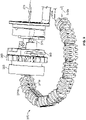
- the drive system 300 may include a number of components, such as an electrically powered actuator (e.g., reversible motor 320 or the like), a drive wheel 360, a bearing 365, a flexible piston rod 370, a piston rod guide 363, and a plunger engagement device 375.
- an electrically powered actuator e.g., reversible motor 320 or the like
- the reversible motor 320 drives a gear system (not shown in FIG. 7 ) to cause the rotation of the drive wheel 360 that is coupled with the bearing 365.
- the drive wheel 360 may include a central aperture with an internal thread pattern, which mates with an external thread pattern on the flexible piston rod 370.
- the interface of the threaded portions of the drive wheel 360 and flexible piston rod 370 may be used to transmit force from the drive wheel to the piston rod 370. Accordingly, in the embodiment of FIG. 7 , the drive wheel 360 is the driver while the flexible piston rod 370 is the driven member. As further described below, the rotation of the drive wheel 360 can drive the flexible piston rod 370 forward in a linear longitudinal direction.
- the flexible piston rod 370 can include an electrically conductive element, such as electrically conductive strips mounted thereto, electrically conductive wires embedded or attached thereto, or electrically conductive polymer that forms the piston rod 370.
- the electrically conductive element of the piston rod 370 can be connected to the electrical connection circuit 318, for example, using flexible wires 372a and 372b.
- one of the wires 372a and 372b is connected to an electrical ground.
- both wires 372a and 372b can be attached to the trailing end of the flexible piston rod 370, thereby reducing the likelihood that the wires 372a and 372b would being entangled with a portion of the medicine cartridge 120 or the drive system (e.g., any part of a combination of the drive wheel 360, piston rod guide 363, and bearing 365) as the leading end of the flexible piston rod 370 moves forward in a linear longitudinal direction.
- the drive system e.g., any part of a combination of the drive wheel 360, piston rod guide 363, and bearing 365
- the electrically conductive element of the drive system detector 380 may comprise one or more conductive strips 371 extending generally continuous along outer surface of the flexible piston rod 370.
- silver conductive paint strips 371a and 371b can be applied to the surface of the flexible piston rod 370 (across the segments and the hinge portions between adjacent segments).
- Such conductive paint allows electrical current to be applied across the flexible piston rod 370 and periodic voltage readings queried by the software component of the drive system detector 380.
- the flexible piston rod 370 is fractured or is otherwise partially or completely severed, one or more segments of at least one of the conductive strips 371a and 371b will also likely be severed.
- the flexible piston rod 370 is no longer electrically connected to ground. Therefore, when the drive system detector 380 takes a voltage reading, the voltage reading will likely be a substantially non-zero value indicating a malfunction of the drive system 300.
- a loop back 373 of the conductive strips 371a and 371b is shown.
- the use of the loop back 373 creates a single U-shaped conductive path that includes conductive strips 371a and 371b and loop back 373.
- One advantage of such an arrangement is that the flexible wires 372a and 372b are connected at the same end of the piston rod 370 (e.g., the trailing end portion in this embodiment). As such, there is no need for a wire connection at the leading end of the piston rod 370 that advances into the medicine cartridge 120 ( FIG. 1 ) as the medicine is dispensed.
- the electrically conductive element of the drive system detector 380 comprises one or more conductive wires 377 applied to a generally continuous outer surface of the flexible piston rod 370.
- flexible conductive wires 377a and 377b can be applied to the surface of the flexible piston rod 370 (across the segments and the hinge portions between adjacent segments).
- the wires 377a and 377b are sheathed in an insulating material, such as a non-conductive flexible polymer or other covering.
- Such flexible wires allow electrical current to be applied across the flexible piston rod 370 and periodic voltage readings queried by the software component of the drive system detector 380 (as previously described).
- the flexible wires 377a and 377b may be different portions of a single wire that are joined at a loopback near the leading end of the piston rod (similar to the loopback 373 shown in FIG. 9 ), thereby creating a single U-shape conductive path.
- the flexible wire portions 377a and 377b extend from the same end of the piston rod 370 (e.g., the trailing end portion in this embodiment)toward the printed circuit board 318. In such circumstances, there is no need for a wire connection at the leading end of the piston rod 370 that advances into the medicine cartridge 120 ( FIG. 1 ) as the medicine is dispensed.
- the flexible piston rod 370 In situations where, for example, the flexible piston rod 370 is fractured or is otherwise partially or completely severed, one or more segments of at least one of the flexible wires 377a and 377b may also be severed. In such circumstances, because the electrical path across the piston rod 370 is disrupted, the flexible piston rod 370 is no longer electrically connected to ground. Therefore, when the software component of the drive system detector 380 queries a voltage reading, the voltage reading will likely be a substantially non-zero value (e.g., a high signal, not ground) indicating the drive system 300 may be broken or otherwise damaged.
- a substantially non-zero value e.g., a high signal, not ground
- some alternative embodiments of the drive system detector 380 may employ one or more conductive wires 377 embedded within the piston rod 370.
- the embedded wires 377 are depicted in an unmagnified view (as shown in FIG. 11A ) and a magnified view (as shown in FIG. 11B ).
- the one or more conductive wires 377 are disposed within corresponding interior channels or cavities of the flexible piston rod 370.
- flexible conductive wires 377a and 377b can be threaded through one or more mostly internal channels (and across the segments and the hinge portions between adjacent segments) created when the flexible piston rod 370 is at least partially manufactured using an insert molding technique.
- FIG. 11B illustrates a magnified view of a number of hinge portions of the flexible rod 370 whereby only a portion of the wires 377a and 377b internal to the flexible piston rod 370 are visible.
- the wires 377a and 377b are sheathed in an insulating material, such as a non-conductive flexible polymer or other covering.
- an insulating material such as a non-conductive flexible polymer or other covering.
- Such flexible wires allow electrical current to be applied across the flexible piston rod 370 and periodic voltage readings queried by the software component of the drive system detector 380.
- the flexible wires 377a and 377b may be different portions of a single wire that are joined at a loopback near the leading end of the piston rod (similar to the loopback 373 shown in FIG. 9 ), thereby creating a single U-shape conductive path.
- one advantage of such an arrangement is that the flexible wire portions 377a and 377b extend from the same end of the piston rod 370 (e.g., the trailing end portion in this embodiment)toward the printed circuit board 318. In such circumstances, there is no need for a wire connection at the leading end of the piston rod 370 that advances into the medicine cartridge 120 ( FIG. 1 ) as the medicine is dispensed. In situations where, for example, the flexible piston rod 370 is fractured or is otherwise partially or completely severed, one or more segments of at least one of the flexible wires 377a and 377b may also be severed at least in part due to their respective integration into the internal structure of the flexible piston rod 370.
- the flexible piston rod 370 is no longer electrically connected to ground. Therefore, when the software component of the drive system detector 380 queries a voltage reading, the voltage reading will likely be a substantially non-zero value (e.g., a high signal, not ground) indicating the drive system 300 may be broken or otherwise damaged.
- a substantially non-zero value e.g., a high signal, not ground
- the piston rod 370 can be constructed using an electrically conductive polymer material.
- the electrical connection to ground is disrupted and a voltage reading of the piston rod 370 will likely be a substantially non-zero value.
- a higher voltage value e.g., not ground
- the infusion pump system 10 can initiate appropriate user safety countermeasures, described in more detail below.
- the drive system detector 380 described in some or all of the aforementioned embodiments can include at least: (1) an electrically conductive element coupled to a piston rod 370 or other component of the drive system 300, and (2) a software component stored in the control circuitry 240 ( FIG. 6 ) that is configured to periodically query or otherwise monitor the electrically conductive element.
- the drive system detector 380 can be configured to sense a change in impedance across the electrically conductive element after the pump device 100 has received an impact force that results in damage to the drive system 300.
- the drive system detector 380 can operate in three different modes: (1) a "normal” mode where pump device 100 and controller device 200 are coupled together, and the conductive element (e.g., the one or more conductive strips, wires or material extending along the piston rod 370 or other component of the drive system 300) is intact; (2) a "damage-detected” mode where the pump device 100 and the controller device 200 are coupled together, but said conductive element coupled to the drive system 300 is broken; and (3) a "disconnected" mode where the pump device 100 and the controller device 200 are not electrically connected, yet the drive system detector 380 passively detects that the pump device 100 has sustained possible damage to the drive system 300 therein.
- the conductive element e.g., the one or more conductive strips, wires or material extending along the piston rod 370 or other component of the drive system 300
- the conductive element coupled to the drive system 300 is not broken-a voltage applied across the conductive element will indicate a first signal type (e.g., a ground or "low” signal that is detected by the software component of the drive system detector 380).
- a first signal type e.g., a ground or "low” signal that is detected by the software component of the drive system detector 380.
- the control circuitry 240 will operate the pump system 10 is in the "normal” mode (e.g., dispensation of the medicine can proceed, along with other pump operations).
- the drive system detector 380 can continue to monitor the status of the drive system 300 by querying the output from the voltage signal applied across the conductive element at regular intervals.
- the controller device 200 In the "drop-detected" mode-where the controller device 200 is coupled together with the pump device 100, but the conductive element coupled to the drive system 300 is broken-a voltage applied across the conductive element will indicate a "high” signal (e.g., measurably larger than the aforementioned ground or “low” signal).
- the "high” signal can be detected by the software component of the drive system detector 380, and in response thereto, the control circuitry 240 in controller device 200 will operate the pump system 10 is in the "drop-detected" mode.
- the controller device 200 can initiate appropriate user safety countermeasures for the pump system 10.
- the drive system detector 380 can provide an alert to the user even if the pump device 100 suffered damage while separated from the controller device 200. In such circumstances, the drive system detector 380 passively detects the possible damage or inoperability of the drive system (e.g., because the conductive element of the drive system detector 380 is broken), which thereby enables the controller device 200 to alert the user prior to attempting to dispense medicine from the pump device 100.
- the software component of the drive system detector 380 may cause a voltage to be applied across the conductive element. If the conductive element is broken (e.g., due to a break in the drive rod 370 or another component of the drive system 300), the drive system detector 380 will detect a "high" signal (e.g., measurably larger than the aforementioned ground or "low” signal). In response thereto, the control circuitry 240 will alert the user and initiate appropriate user safety countermeasures for the pump system 10 prior to dispensing medicine from the pump device 100.
- a "high” signal e.g., measurably larger than the aforementioned ground or "low” signal
- a controller of an infusion pump system can implement a process 400 of detecting damage to the drive system 300 ( FIG. 7 ) using a drive system detector of the infusion pump system.
- a process 400 for example, can be implemented by the controller device 200 of the pump system 10 ( FIG. 1 ).
- some operations of the process 400 could be implemented in an infusion pump system in which the controller and the pump drive system are integrated into a single housing.
- the controller device can receive an electrical signal indicating that an electrical connection with an electrically conductive element of a drive system detector.
- the two components can be electrically connected via the connectors 118 and 218.
- the controller device 200 can be electrically connected to an electrically conductive element of the drive system detector (e.g., the one or more conductive strips or wires coupled to the piston rod, an electrically conductive material of the piston rod, or the like), and the signal can indicative of the voltage across the flexible piston rod 370 as described above in reference to FIGS. 7-11 .
- the controller device monitors the status of the drive system detector.
- a monitoring operation can include periodic samplings of a voltage value indicating the voltage or electrical impedance measured across the flexible piston rod 370 ( FIG. 7 ).
- the monitoring operation 412 would reveal a signal (e.g., corresponding to a voltage or electrical impedance value) that is different (e.g., where the voltage value or electrical impedance is substantially zero or ground) from the signal when in the "drive system error" mode. That is, in some embodiments described above, a "drive system error” mode may be signaled when the drive system 300 is in a mode of operation whereby the voltage value or electrical impedance measured of the flexible piston rod 370 is substantially greater than ground.
- the controller device determines if the drive system detector indicates damage to the drive system. For example, in the embodiments shown in FIGS. 7-11 , the drive system detector 380 can indicate that damage to the flexible piston rod 370 occurred when a voltage value greater than zero (e.g., not ground) is detected by a software component of the drive detector 380 (and thereby indicating a "drive system error" mode). If the drive detector does not indicate that damage to the drive system 300 has occurred, the process 400 returns to the monitoring operation 412.
- a voltage value greater than zero e.g., not ground
- the monitoring operation 412 would indicate damage to the drive system based on a measurement of a voltage value corresponding to electrical current applied across the flexible piston rod 370. If the "drive system error” mode is signaled immediately upon connect of the pump device 100 to the controller device 200 (e.g., the pump device 100 experienced a significant impact when separated from the controller device 200), the repeated cycle of monitoring damage sustained to the drive system could be bypassed.
- the controller device can respond according to some or all of the operations 416, 418, 420, 422, 424, and 426.
- the controller device in response to the controller device's determination that the drive detector system indicates the drive system 300 has sustained damage or is otherwise inoperable, the controller device can act to disable the pump drive system.
- the pump system 10 may immediately stop the delivery of medicine to the user of the system. As described above, the cessation of medicine delivery can be an appropriate user safety precaution because damage to the drive system 300 may cause an over-dosage or under-dosage could occur of medicine, depending on particular circumstances.
- the process 400 can instead include an operation in which the user is prompted to confirm/approve that the pump drive system can be disabled.
- the controller device can initiate further user safety countermeasures as described in the next steps of operation process 400.
- the controller device can emit an audible alarm in response to a determination of damage to the drive system (e.g., drive system 300).
- the purpose of the audible alarm is to alert the user to the issue that the pump system 10 is not operating normally and requires attention.
- the audible alarm can be emitted before, after, or simultaneously with the operation 416 of disabling the drive system.
- a separate light device of the pump system can be activated to provide a visible alarm (in addition to the audible alarm of operation 418).
- the inspection light device 230 of pump system 10 can be activated to provide a visual notification to the user to the issue that the pump system 10 is not operating normally and requires attention.
- the controller device can display a message to indicate that a drop event was detected in response to a determination of an impact at or above the threshold level.
- the user interface display screen 222 on the controller device 200 can display a short textual message to alert the user (e.g., "Drive System Error").
- the message can provide the user with an explanation of the reason for the audible and visual alarms. Further, the message can provide the user with an explanation that the pump drive system was automatically disabled.
- the controller device can display a message prompting the user to remove the infusion set from the user's body.
- the user interface display screen 222 on the controller device 200 can display the message prompting the user to remove the infusion set from the user's body. This message can be provided in order to assist the user with taking the proper actions to prevent an over dispensation of medicine tot eh user's body as a result of the detected impact.
- the controller device can display a message prompting the user to detach the pump device from the controller device.
- the user interface display screen 222 on the controller device 200 can display a message prompting the user to detach the pump device 100 from the controller device 200.
- the pump device 100 that sustained damage to the drive system 300 will need to be removed from the controller device 200 so that a new pump device, such as pump device 100' (refer to FIGS. 4 and 5 ) can be coupled with the controller device 200.
- This message assists the user to take the proper actions in response to damage detected by the drive system detector, and to proceed towards resumption of the use of a properly functioning pump system 10.
- a portable infusion pump system 700 having a drive system detector 780 can employ a reusable pump apparatus (rather than a disposable pump device as previously described).
- the infusion pump system 700 may comprise a reusable device that houses the control circuitry and the pump drive system within a single housing construct.
- the pump system 700 comprises a reusable pump device that houses both the controller circuitry and the pump drive system (which may include a piston rod 370 and one or more gears 365).
- the pump system 700 can include a housing structure that defines a cavity in which a medicine cartridge can be received (not shown in FIG. 13 ; refer for example to cartridge 120 in FIG. 1 ).
- the pump system 700 can be adapted to receive a medicine cartridge in the form of a carpule that is preloaded with insulin or another medicine.
- the pump drive system can act upon the fluid cartridge to controllably dispense medicine through an infusion set 146 and into the user's tissue or vasculature.
- the user can wear the portable pump system 700 on the user's skin under clothing or in the user's pocket while receiving the medicine dispensed through the infusion set 146.
- the infusion pump system 700 may include the drive system detector 780 that can detect damage to one or more components of the drive system (e.g., one or more of the piston rod 770 and the gears 765).
- the drive system detector 780 may include one or more conductive elements mounted to respective components of the drive system, and may also include a software component configured to query the one or more conductive elements.
- the occurrence of damage the drive system e.g., damage to the piston rod 370, damage or non-alignment of one or more gears 365, or the like
- damage may occur, for example, when the pump system 700 is exposed to an impact force, for example, by dropping the infusion pump system 700 onto a floor or other hard surface, and by subjecting the infusion pump system 700 other types of impacts.
- the drive system detector 780 of the infusion pump system 700 can operate similarly to any of the embodiments described above, such as the conductive strip embodiments depicted in FIGS. 7-9 , the external conductive wire embodiment depicted in FIG. 10 , the internal conductive wire embodiment depicted in FIG. 11 , or the embodiment in which a component of the drive system comprises a conductive material as described above.
- the electrical connections associated with the drive system detector for use with the mechanism 780 can be similar to the drive system detector electrical connections described in reference to FIGS. 7-11 , but with a few adaptations.
- the drop detector circuit may not necessarily communicate via the electrical connectors 118 and 218. Consequently, the drive detector electrical connections used with the drive system detector 780 in the infusion pump system 700 may optionally be a simplified version of the drive system detector 380 depicted in FIG. 7 .
- the user interface 720 of the pump system 700 includes a display device 722 and one or more user-selectable buttons 724a-e.
- the display device 722 can include an active area in which numerals, text, symbols, images, or a combination thereof can be displayed (as shown, for example, in FIG. 13 ).
- the display device 722 can be used to communicate to the user that a drop event has been detected and the drive system has been disabled (similar to the process described in reference to FIG. 12 ).
- the display device 722 can be used to communicate a number of settings or menu options for the infusion pump system 700.
- the display device 722 can be used to communicate medicinal delivery information 727, such as the basal delivery rate, a bolus dosage, a historical record of medicine delivered, the amount of medicine remaining in the cartridge, or the like.
- the display device 722 can be used to communicate time and date information, which can be used by the user to determine dosage schedules, bolus delivery times, meal times, or the like.
- the user may press one or more of the buttons 724a, 724b, 724c, 724d, and 724e to shuffle through a number of menus or program screens that show particular settings and data (e.g., review data that shows the medicine dispensing rate, the total amount of medicine dispensed in a given time period, the amount of medicine scheduled to be dispensed at a particular time or date, the approximate amount of medicine remaining in the cartridge 120, or the like).
- the user can adjust the settings or otherwise program the pump system 700 by pressing one or more buttons 724a, 724b, 724c, 724d, and 724e of the user interface 420.
- the user can contemporaneously monitor the operation of the pump system 700, including any messages pertaining to the drop detection system from the same user interface 720.
Landscapes
- Health & Medical Sciences (AREA)
- Vascular Medicine (AREA)
- Engineering & Computer Science (AREA)
- Anesthesiology (AREA)
- Biomedical Technology (AREA)
- Heart & Thoracic Surgery (AREA)
- Hematology (AREA)
- Life Sciences & Earth Sciences (AREA)
- Animal Behavior & Ethology (AREA)
- General Health & Medical Sciences (AREA)
- Public Health (AREA)
- Veterinary Medicine (AREA)
- Infusion, Injection, And Reservoir Apparatuses (AREA)
Claims (15)
- Ein medizinisches Infusionspumpensystem (10), das Folgendes beinhaltet:ein tragbares Gehäuse (110), das einen Raum (116) zum Aufnehmen eines Arzneimittels definiert;ein Pumpenantriebssystem (300) zum Abgeben von Arzneimittel aus dem tragbaren Gehäuse, wenn das Arzneimittel in dem Raum aufgenommen ist;einen Steuerschaltkreis (200), der konfiguriert ist, um mit dem Pumpenantriebssystem zum Steuern der Abgabe des Arzneimittels aus dem tragbaren Gehäuse elektrisch zu kommunizieren, wenn das Arzneimittel in dem Raum aufgenommen ist;dadurch gekennzeichnet, dass das medizinische Infusionspumpensystem Folgendes umfasst:einen Antriebssystemdetektor (380), der mindestens ein elektrisch leitendes Element (370, 371, 377, 379) beinhaltet, das mit einer oder mehreren Komponenten (370) des Pumpenantriebssystems (300) gekoppelt ist, wobei der Antriebssystemdetektor konfiguriert ist, um eine Änderung eines elektrischen Merkmals des mindestens einen elektrisch leitenden Elements zu erkennen, wobei der Antriebssystemdetektor konfiguriert ist, um einen Schaden der einen oder der mehreren Komponenten des Pumpenantriebssystems anzugeben, wenn eine Änderung des elektrischen Merkmals des mindestens einen elektrisch leitenden Elements erkannt wird,wobei der Steuerschaltkreis in elektrischer Kommunikation mit dem Antriebssystemdetektor steht und wobei der Steuerschaltkreis konfiguriert ist, um das Pumpenantriebssystem als Antwort darauf, dass der Antriebssystemdetektor einen Schaden der einen oder der mehreren Komponenten des Pumpenantriebssystems angibt, abzuschalten.
- Medizinisches Infusionspumpensystem gemäß Anspruch 1, wobei der Antriebssystemdetektor konfiguriert ist, um einen Schaden der einen oder der mehreren Komponenten des Pumpenantriebssystems anzugeben, wenn der Antriebssystemdetektor erkennt, dass die Änderung des elektrischen Merkmals auf einen Nichtnullwert oder einen wesentlich größeren Wert als Null erfolgt.
- Medizinisches Infusionspumpensystem gemäß Anspruch 1, wobei der Steuerschaltkreis in elektrischer Kommunikation mit dem Antriebssystemdetektor steht, sodass der Steuerschaltkreis einen Alarm auslöst, wenn der Antriebssystemdetektor erkennt, dass die Änderung des elektrischen Merkmals auf einen wesentlich größeren Wert als Null erfolgt.
- Medizinisches Infusionspumpensystem gemäß Anspruch 1, wobei die eine oder die mehreren Komponenten eine Kolbenstange des Pumpenantriebssystems beinhalten.
- Medizinisches Infusionspumpensystem gemäß Anspruch 4, wobei das elektrisch leitende Element mindestens eines von (i) einem elektrisch leitenden Streifen (371), der auf der Oberfläche der Kolbenstange angebracht ist, (ii) einem elektrisch leitenden Draht (377), der auf der Oberfläche der Kolbenstange befestigt ist, (iii) einem elektrisch leitenden Draht (377), der in der Kolbenstange eingebettet ist, beinhaltet.
- Medizinisches Infusionspumpensystem gemäß Anspruch 4, wobei das elektrisch leitende Element einen leitenden Farbstreifen beinhaltet, der auf einer Oberfläche der Kolbenstange angebracht ist und in zwei im Wesentlichen parallelen Linien eingerichtet ist, die sich an einer Rückschleife (373) in der Nähe eines vorderen Endes der Kolbenstange verbinden, um einen kontinuierlichen U-förmigen elektrischen Pfad zu bilden;oder wobei das elektrisch leitende Element einen leitenden Draht beinhaltet, der auf einer Oberfläche der Kolbenstange befestigt ist, wobei der erste und der zweite Abschnitt des leitenden Drahts mit Bezug aufeinander im Wesentlichen parallel sind und an einem elektrisch leitenden Rückschleifenpfad in der Nähe eines vorderen Endes der Kolbenstange zusammenlaufen, um einen kontinuierlichen U-förmigen elektrischen Pfad zu bilden;oder wobei das elektrisch leitende Element einen leitenden Draht beinhaltet, der in einer Kolbenstange des Antriebssystems eingebettet ist, wobei der erste und der zweite Abschnitt des leitenden Drahts mit Bezug aufeinander im Wesentlichen parallel sind und an einem elektrisch leitenden Rückschleifenpfad in der Nähe eines vorderen Endes der Kolbenstange zusammenlaufen, um einen kontinuierlichen U-förmigen elektrischen Pfad zu bilden.
- Medizinisches Infusionspumpensystem gemäß Anspruch 1, wobei mindestens ein elektrisch leitendes Element eine elektrisch leitende Kolbenstange des Pumpenantriebssystems beinhaltet, die aus einem elektrisch leitenden Material gebildet ist.
- Medizinisches Infusionspumpensystem gemäß Anspruch 1, wobei der Steuerschaltkreis als Antwort darauf, dass der Antriebssystemdetektor eine Änderung des elektrischen Merkmals des elektrisch leitenden Elements auf einen wesentlich größeren Wert als Null erkennt, eine Anzeige einer oder mehrerer Alarmmeldungen auf einer Benutzeroberflächenanzeige (222), die sich auf dem medizinischen Infusionspumpensystem befindet, bewirkt und bewirkt, dass eine Inspektionsleuchte (230) aufleuchtet, wobei sich die Inspektionsleuchte von der Benutzeroberflächenanzeige unterscheidet.
- Medizinisches Infusionspumpensystem gemäß Anspruch 1, wobei der Steuerschaltkreis in einem Steuerungsgehäuse (210) untergebracht ist, das entfernbar an dem tragbaren Gehäuse (110) befestigbar ist.
- Medizinisches Infusionspumpensystem gemäß Anspruch 9, wobei das Pumpenantriebssystem in dem tragbaren Gehäuse untergebracht ist und einer oder mehrere elektrische Kontakte, die auf dem Steuerungsgehäuse angeordnet sind, in entsprechende elektrische Kontakte, die auf dem tragbaren Gehäuse angeordnet sind, eingreifbar sind, wenn das Steuerungsgehäuse entfernbar an dem tragbaren Gehäuse befestigt wird.
- Medizinisches Infusionspumpensystem gemäß Anspruch 1, wobei der Antriebssystemdetektor ferner computerlesbare Anweisungen beinhaltet, die auf einem computerlesbaren Medium des Steuerschaltkreises gespeichert sind und die, wenn sie von einem Prozessor des Steuerschaltkreises ausgeführt werden, ein elektrisches Merkmal des mindestens einen elektrisch leitenden Elements, das mit der einen oder den mehreren Komponenten des Pumpenantriebssystems gekoppelt ist, messen.
- Ein Verfahren zum Steuern eines medizinischen Infusionspumpensystems (10) gemäß einem der Ansprüche 1 bis 11, das Folgendes beinhaltet:Wahrnehmen, dass das Pumpenantriebssystem des medizinischen Infusionspumpensystems beschädigt ist, über den Antriebssystemdetektor (380), der das mindestens eine elektrisch leitende Element (370, 371, 377, 379) umfasst, das mit der einen oder den mehreren Komponenten des Pumpenantriebssystems in dem medizinischen Infusionspumpensystem gekoppelt ist; undals Antwort auf das Wahrnehmen, dass der Antriebssystemdetektor angibt, dass das Pumpenantriebssystem beschädigt ist, Abschalten des Pumpenantriebssystems, das in dem medizinischen Infusionspumpensystem untergebracht ist.
- Verfahren gemäß Anspruch 12, das als Antwort auf das Wahrnehmen, dass der Antriebssystemdetektor angibt, dass das Pumpenantriebssystem beschädigt ist, ferner das Ausgeben eines hörbaren Alarms beinhaltet.
- Verfahren gemäß Anspruch 13, das als Antwort auf das Wahrnehmen, dass der Antriebssystemdetektor angibt, dass das Pumpenantriebssystem beschädigt ist, ferner das Anzeigen einer oder mehrerer Warntextnachrichten auf einer Benutzeroberflächenanzeige (222) des medizinischen Infusionspumpensystems beinhaltet.
- Verfahren gemäß Anspruch 14, das als Antwort auf das Wahrnehmen, dass der Antriebssystemdetektor angibt, dass das Pumpenantriebssystem beschädigt ist, ferner das Aktivieren einer Lichtquelle (230) des medizinischen Infusionspumpensystems, die sich von der Benutzeroberflächenanzeige (222) unterscheidet, beinhaltet.
Applications Claiming Priority (2)
| Application Number | Priority Date | Filing Date | Title |
|---|---|---|---|
| US13/709,296 US9427523B2 (en) | 2012-12-10 | 2012-12-10 | Infusion pump system and method |
| PCT/US2013/073883 WO2014093226A1 (en) | 2012-12-10 | 2013-12-09 | Infusion pump system and method |
Publications (3)
| Publication Number | Publication Date |
|---|---|
| EP2928523A1 EP2928523A1 (de) | 2015-10-14 |
| EP2928523A4 EP2928523A4 (de) | 2016-08-03 |
| EP2928523B1 true EP2928523B1 (de) | 2022-11-09 |
Family
ID=50881738
Family Applications (1)
| Application Number | Title | Priority Date | Filing Date |
|---|---|---|---|
| EP13862133.9A Active EP2928523B1 (de) | 2012-12-10 | 2013-12-09 | Infusionspumpensystem und -verfahren |
Country Status (3)
| Country | Link |
|---|---|
| US (4) | US9427523B2 (de) |
| EP (1) | EP2928523B1 (de) |
| WO (1) | WO2014093226A1 (de) |
Families Citing this family (15)
| Publication number | Priority date | Publication date | Assignee | Title |
|---|---|---|---|---|
| US9427523B2 (en) * | 2012-12-10 | 2016-08-30 | Bigfoot Biomedical, Inc. | Infusion pump system and method |
| USD829434S1 (en) * | 2016-04-29 | 2018-10-02 | Csl Behring Recombinant Facility Ag | Syringe pump housing |
| USD831821S1 (en) * | 2016-04-29 | 2018-10-23 | Csl Behring Recombinant Facility Ag | Syringe pump housing |
| USD831820S1 (en) * | 2016-04-29 | 2018-10-23 | Csl Behring Recombinant Facility Ag | Syringe pump housing |
| USD831194S1 (en) * | 2016-04-29 | 2018-10-16 | Csl Behring Recombinant Facility Ag | Syringe pump housing |
| AU2017335635B2 (en) | 2016-09-29 | 2023-01-05 | Smith & Nephew, Inc. | Construction and protection of components in negative pressure wound therapy systems |
| WO2018096534A1 (en) | 2016-11-22 | 2018-05-31 | Sorrel Medical Ltd. | Apparatus for delivering a therapeutic substance |
| EP3592313B2 (de) | 2017-03-07 | 2024-12-18 | Smith & Nephew, Inc | Verbesserte drucktherapiesysteme und verfahren mit einer antenne |
| US20230123806A1 (en) | 2017-07-07 | 2023-04-20 | Neuroderm, Ltd. | Device for subcutaneous delivery of fluid medicament |
| RU2765171C2 (ru) | 2017-07-07 | 2022-01-26 | Нейродерм Лтд | Устройство для подкожной доставки текучего лекарственного средства |
| AU201810653S (en) * | 2017-12-06 | 2018-05-04 | Nutricia Nv | Control panels with displays for feeding devices [medical] |
| US20190341149A1 (en) * | 2018-05-07 | 2019-11-07 | Medtronic Minimed, Inc. | Augmented reality guidance for medical devices |
| EP3744368B1 (de) | 2018-10-05 | 2026-02-18 | LTS Device Technologies Ltd | Auslösesequenz |
| CN111053956A (zh) * | 2019-12-24 | 2020-04-24 | 微泰医疗器械(杭州)有限公司 | 一种给药器及给药泵系统 |
| DE202021103538U1 (de) * | 2021-07-01 | 2021-08-09 | B. Braun Melsungen Aktiengesellschaft | Trage-/ Haltevorrichtung mit einem intelligenten Cover für medizinische Fluidpumpen |
Family Cites Families (167)
| Publication number | Priority date | Publication date | Assignee | Title |
|---|---|---|---|---|
| GB747701A (en) | 1953-12-16 | 1956-04-11 | Lines Bros Ltd | Improvements in apparatus for controlling movements of model ships or other toys |
| FR2585252B1 (fr) | 1985-07-26 | 1990-06-15 | Gazuit Ste Nle Electronique | Pousse-seringue |
| GB2218831A (en) | 1988-05-17 | 1989-11-22 | Mark John Newland | Personal medical apparatus |
| AU5933490A (en) | 1989-06-21 | 1991-01-08 | Johnson Service Company | A shape memory actuator |
| AU641206B2 (en) | 1991-01-22 | 1993-09-16 | Eli Lilly And Company | Multiple dose injection pen |
| DK69491D0 (da) | 1991-04-18 | 1991-04-18 | Novo Nordisk As | Pumpe |
| US5719761A (en) | 1993-01-15 | 1998-02-17 | Alaris Medical Systems, Inc. | Configuration control system for configuring multiple biomedical devices |
| DK109293D0 (da) | 1993-09-27 | 1993-09-27 | Novo Nordisk As | Apparat |
| DE69637358T2 (de) | 1995-05-12 | 2008-04-17 | Seiko Epson Corp. | Gerät zur Kontrolle eines physiologischen Zustands |
| ZA9610374B (en) | 1995-12-11 | 1997-06-23 | Elan Med Tech | Cartridge-based drug delivery device |
| DE19627619A1 (de) | 1996-07-09 | 1998-01-15 | Orlita Prozesstechnik Orlita G | Antrieb für eine Membran- oder Kolbenpumpe für die Dosierung von Medien |
| WO1998011927A1 (de) | 1996-09-20 | 1998-03-26 | Disetronic Licensing Ag | Abtriebsglied für den vorschub eines stopfens einer spritzampulle und stopfen hierzu |
| US6558351B1 (en) | 1999-06-03 | 2003-05-06 | Medtronic Minimed, Inc. | Closed loop system for controlling insulin infusion |
| WO1998057683A1 (en) | 1997-06-16 | 1998-12-23 | Elan Corporation, Plc. | Pre-filled drug-delivery device and method of manufacture and assembly of same |
| US6796970B1 (en) | 1997-06-17 | 2004-09-28 | Novo Nordisk A/S | Dose setting device |
| AU8333298A (en) | 1997-07-14 | 1999-02-10 | Novo Nordisk A/S | Cylinder ampoule |
| ATE293465T1 (de) | 1997-10-23 | 2005-05-15 | Morten Mernoe | Infusionspumpensystem und -einheit |
| AU2492199A (en) | 1998-02-03 | 1999-08-16 | Board Of Trustees Of Michigan State University | Thin film fluid control systems and method of fabricating the same |
| WO1999048546A1 (en) | 1998-03-23 | 1999-09-30 | Elan Corporation, Plc | Drug delivery device |
| PT1077636E (pt) | 1998-05-13 | 2004-06-30 | Cygnus Therapeutic Systems | Processamento de sinal para medicao de analitos fisiologicos |
| TW406018B (en) | 1998-05-21 | 2000-09-21 | Elan Corp Plc | Improved adhesive system for medical devices |
| AU4769599A (en) | 1998-07-08 | 2000-02-01 | Novo Nordisk A/S | A medical delivery device and a cartridge assembly for use in the same |
| US6554798B1 (en) | 1998-08-18 | 2003-04-29 | Medtronic Minimed, Inc. | External infusion device with remote programming, bolus estimator and/or vibration alarm capabilities |
| US6558320B1 (en) | 2000-01-20 | 2003-05-06 | Medtronic Minimed, Inc. | Handheld personal data assistant (PDA) with a medical device and method of using the same |
| DE19840965A1 (de) | 1998-09-08 | 2000-03-09 | Disetronic Licensing Ag | Vorrichtung zur Selbstverabreichung eines Produktfluids |
| EP2229879A1 (de) | 1998-10-08 | 2010-09-22 | Medtronic MiniMed, Inc. | Kennzeichenmonitoringsystem mit Fernmessung |
| CA2669175C (en) * | 1998-10-29 | 2014-01-28 | Medtronic Minimed, Inc. | Reservoir connector |
| US7193521B2 (en) | 1998-10-29 | 2007-03-20 | Medtronic Minimed, Inc. | Method and apparatus for detecting errors, fluid pressure, and occlusions in an ambulatory infusion pump |
| US6605067B1 (en) | 1998-11-20 | 2003-08-12 | Novo Nordisk A/S | Injection needle |
| US6540672B1 (en) | 1998-12-09 | 2003-04-01 | Novo Nordisk A/S | Medical system and a method of controlling the system for use by a patient for medical self treatment |
| DE19916876A1 (de) | 1999-04-14 | 2000-11-02 | Clemens Micheler | Medizinische Dosierpumpe |
| US6461331B1 (en) | 1999-05-21 | 2002-10-08 | Minimed Inc. | Device and method for infusion of small molecule insulin mimetic materials |
| US6752787B1 (en) | 1999-06-08 | 2004-06-22 | Medtronic Minimed, Inc., | Cost-sensitive application infusion device |
| TW453884B (en) | 1999-09-16 | 2001-09-11 | Novo Nordisk As | Dose setting limiter |
| US6659978B1 (en) | 1999-10-04 | 2003-12-09 | Seiko Instruments Inc. | Portable dosing apparatus |
| DE19947826B4 (de) | 1999-10-05 | 2006-06-08 | Disetronic Licensing Ag | Vorrichtung zur dosierten Verabreichung eines injizierbaren Produkts |
| US6648821B2 (en) | 2000-01-21 | 2003-11-18 | Medtronic Minimed, Inc. | Microprocessor controlled ambulatory medical apparatus with hand held communication device |
| WO2001054757A1 (en) | 2000-01-28 | 2001-08-02 | Novo Nordisk A/S | A dose setting limiter |
| DE10006044A1 (de) | 2000-02-10 | 2001-08-16 | Roche Diagnostics Gmbh | Anordnung und Verfahren zur Dosierung eines die Blutglukose eines Patienten regulierenden Hormons |
| US6572542B1 (en) | 2000-03-03 | 2003-06-03 | Medtronic, Inc. | System and method for monitoring and controlling the glycemic state of a patient |
| EP1136698A1 (de) | 2000-03-17 | 2001-09-26 | Seiko Epson Corporation | Temperaturunterschiedantrieb und elektrische Vorrichtung, Uhrwerk und helles elektrisches Gerät mit diesem Antrieb |
| TW523415B (en) | 2000-03-24 | 2003-03-11 | Novo Nordisk As | A flexible piston rod |
| US6485465B2 (en) | 2000-03-29 | 2002-11-26 | Medtronic Minimed, Inc. | Methods, apparatuses, and uses for infusion pump fluid pressure and force detection |
| US6485461B1 (en) | 2000-04-04 | 2002-11-26 | Insulet, Inc. | Disposable infusion device |
| US6585699B2 (en) | 2000-04-13 | 2003-07-01 | Nna/S | Drug delivery device provided with a one-way mechanism |
| US6544229B1 (en) | 2000-05-01 | 2003-04-08 | Baxter International Inc | Linearly motile infusion pump |
| US6533183B2 (en) | 2000-05-03 | 2003-03-18 | Novo Nordisk A/S | Coding of cartridges for an injection device |
| US6692472B2 (en) | 2000-05-04 | 2004-02-17 | Novo Nordisk A/S | Injection device, a preassembled dose setting and injection mechanism for an injection device, and a method of assembling an injection device |
| US6716198B2 (en) | 2000-05-18 | 2004-04-06 | Novo Nordisk A/S | Injection device |
| US7005078B2 (en) | 2000-05-25 | 2006-02-28 | Debiotech Sa | Micromachined fluidic device and method for making same |
| JP2003534103A (ja) | 2000-05-30 | 2003-11-18 | ノボ ノルディスク アクティーゼルスカブ | 交換可能な共同動作モジュールを有する薬物供給装置およびその製造方法 |
| TW499314B (en) | 2000-05-30 | 2002-08-21 | Novo Nordisk As | A medication delivery device with replaceable cooperating modules and a method of making same |
| ES2230318T3 (es) | 2000-05-31 | 2005-05-01 | Mnemoscience Gmbh | Materias termoplasticas con memoria de forma yredes polimeras para ingenieria de tejidos. |
| US6547764B2 (en) | 2000-05-31 | 2003-04-15 | Novo Nordisk A/S | Double pointed injection needle |
| US6663602B2 (en) | 2000-06-16 | 2003-12-16 | Novo Nordisk A/S | Injection device |
| US6650951B1 (en) | 2000-06-19 | 2003-11-18 | International Business Machines Corporation | Method and insulin pump for providing a forgotten bolus warning |
| AU2001278417A1 (en) | 2000-07-14 | 2002-01-30 | Novo-Nordisk A/S | A liquid medication delivery device and a method of delivering an intended dose |
| US6589229B1 (en) | 2000-07-31 | 2003-07-08 | Becton, Dickinson And Company | Wearable, self-contained drug infusion device |
| US6554800B1 (en) | 2000-08-09 | 2003-04-29 | Medtronic Minimed, Inc. | Compact pump motor system and dispensing process |
| US6669090B2 (en) | 2000-08-10 | 2003-12-30 | Novo Nordick A/S | Electronic marking of a medication cartridge |
| JP4532823B2 (ja) | 2000-08-18 | 2010-08-25 | ベクトン・ディキンソン・アンド・カンパニー | 流速の選択が可能かつ滴定が可能なボーラスボタン付きの定速流体送出装置 |
| JP2004521667A (ja) | 2000-09-08 | 2004-07-22 | インシュレット コーポレイション | 患者の輸液のための装置、システム及び方法 |
| US20040260233A1 (en) | 2000-09-08 | 2004-12-23 | Garibotto John T. | Data collection assembly for patient infusion system |
| US6669669B2 (en) | 2001-10-12 | 2003-12-30 | Insulet Corporation | Laminated patient infusion device |
| WO2002024257A1 (en) | 2000-09-22 | 2002-03-28 | Novo Nordisk A/S | A medication delivery device |
| EP1332440B1 (de) | 2000-10-04 | 2012-04-11 | Insulet Corporation | Anordnung zum erfassen von daten für ein infusionssystem |
| US6537251B2 (en) | 2000-10-05 | 2003-03-25 | Novo Nordisk A/S | Medication delivery device with bended piston rod |
| US6508788B2 (en) | 2000-10-27 | 2003-01-21 | Novo Nordisk A/S | Medication delivery device with telescopic piston rod |
| DE60126325T2 (de) | 2000-11-09 | 2007-11-08 | Insulet Corp., Beverly | Gerät zur transkutanen abgabe von medikamenten |
| US6922590B1 (en) | 2000-11-21 | 2005-07-26 | Advanced Bionics Corporation | Systems and methods for treatment of diabetes by electrical brain stimulation and/or drug infusion |
| US7054836B2 (en) | 2000-11-30 | 2006-05-30 | Novo Nordisk A/S | Method for assisting a customer in building a build-to-order medical device |
| CA2431420C (en) | 2000-12-21 | 2011-10-11 | Insulet Corporation | Medical apparatus remote control and method |
| US6799149B2 (en) | 2000-12-29 | 2004-09-28 | Medtronic, Inc. | Therapy management techniques for an implantable medical device |
| US6899699B2 (en) | 2001-01-05 | 2005-05-31 | Novo Nordisk A/S | Automatic injection device with reset feature |
| WO2002057627A1 (en) | 2001-01-17 | 2002-07-25 | M 2 Medical A/S | Shape memory alloy actuator |
| JP4278382B2 (ja) | 2001-02-14 | 2009-06-10 | ノボ ノルディスク アクティーゼルスカブ | 電子制御される注射器即ち注入装置 |
| CA2434731C (en) | 2001-02-22 | 2010-01-26 | Insulet Corporation | Modular infusion device and method |
| US6854620B2 (en) | 2001-04-13 | 2005-02-15 | Nipro Diabetes, Systems, Inc. | Drive system for an infusion pump |
| DE60212837T2 (de) | 2001-06-11 | 2007-06-21 | Glaxo Group Ltd., Greenford | Medikamentenspender |
| US6691043B2 (en) | 2001-08-28 | 2004-02-10 | Maxi-Med, Llc | Bolus calculator |
| US6827702B2 (en) | 2001-09-07 | 2004-12-07 | Medtronic Minimed, Inc. | Safety limits for closed-loop infusion pump control |
| US6740072B2 (en) | 2001-09-07 | 2004-05-25 | Medtronic Minimed, Inc. | System and method for providing closed loop infusion formulation delivery |
| US20030055380A1 (en) | 2001-09-19 | 2003-03-20 | Flaherty J. Christopher | Plunger for patient infusion device |
| US20030088238A1 (en) | 2001-09-26 | 2003-05-08 | Poulsen Jens Ulrik | Modular drug delivery system |
| US6723077B2 (en) | 2001-09-28 | 2004-04-20 | Hewlett-Packard Development Company, L.P. | Cutaneous administration system |
| US20040078028A1 (en) | 2001-11-09 | 2004-04-22 | Flaherty J. Christopher | Plunger assembly for patient infusion device |
| US7311693B2 (en) | 2001-11-26 | 2007-12-25 | Nilimedix Ltd. | Drug delivery device and method |
| US7291126B2 (en) | 2001-11-26 | 2007-11-06 | Nilimedix Ltd. | Drug delivery device and method |
| US6736796B2 (en) | 2001-11-26 | 2004-05-18 | Nili-Med Ltd. | Fluid drug delivery device |
| ATE420687T1 (de) | 2001-11-30 | 2009-01-15 | Novo Nordisk As | Nadelsicherheitsvorrichtung |
| US6715516B2 (en) | 2001-12-19 | 2004-04-06 | Novo Nordisk A/S | Method and apparatus for filling cartridges with a liquid |
| US6786890B2 (en) | 2002-01-25 | 2004-09-07 | Novo Nordisk A/S | Linear actuator and a medical delivery device comprising such linear actuator |
| US7033338B2 (en) * | 2002-02-28 | 2006-04-25 | Smiths Medical Md, Inc. | Cartridge and rod for axially loading medication pump |
| US6744350B2 (en) | 2002-02-28 | 2004-06-01 | Smiths Medical Md, Inc. | Insulin pump having missed meal bolus alarm |
| US6852104B2 (en) | 2002-02-28 | 2005-02-08 | Smiths Medical Md, Inc. | Programmable insulin pump |
| US6692457B2 (en) | 2002-03-01 | 2004-02-17 | Insulet Corporation | Flow condition sensor assembly for patient infusion device |
| US6830558B2 (en) | 2002-03-01 | 2004-12-14 | Insulet Corporation | Flow condition sensor assembly for patient infusion device |
| US6936006B2 (en) | 2002-03-22 | 2005-08-30 | Novo Nordisk, A/S | Atraumatic insertion of a subcutaneous device |
| US6656158B2 (en) | 2002-04-23 | 2003-12-02 | Insulet Corporation | Dispenser for patient infusion device |
| US20050238507A1 (en) | 2002-04-23 | 2005-10-27 | Insulet Corporation | Fluid delivery device |
| US6960192B1 (en) | 2002-04-23 | 2005-11-01 | Insulet Corporation | Transcutaneous fluid delivery system |
| US6656159B2 (en) | 2002-04-23 | 2003-12-02 | Insulet Corporation | Dispenser for patient infusion device |
| US20040153032A1 (en) | 2002-04-23 | 2004-08-05 | Garribotto John T. | Dispenser for patient infusion device |
| US6723072B2 (en) | 2002-06-06 | 2004-04-20 | Insulet Corporation | Plunger assembly for patient infusion device |
| US20080132842A1 (en) | 2002-06-06 | 2008-06-05 | Flaherty J Christopher | Plunger assembly for patient infusion device |
| JP2005532129A (ja) | 2002-07-10 | 2005-10-27 | ノボ・ノルデイスク・エー/エス | 投与量設定リミッタを備える注入器 |
| US6945961B2 (en) | 2002-07-10 | 2005-09-20 | Novo Nordisk A/S | Injection device |
| US20040010207A1 (en) | 2002-07-15 | 2004-01-15 | Flaherty J. Christopher | Self-contained, automatic transcutaneous physiologic sensing system |
| US7018360B2 (en) | 2002-07-16 | 2006-03-28 | Insulet Corporation | Flow restriction system and method for patient infusion device |
| EP1391794A1 (de) | 2002-07-23 | 2004-02-25 | Novo Nordisk A/S | Vorrichtung mit Zeitanzeige |
| AU2003245872A1 (en) | 2002-07-24 | 2004-02-09 | M 2 Medical A/S | An infusion pump system, an infusion pump unit and an infusion pump |
| US20050160858A1 (en) | 2002-07-24 | 2005-07-28 | M 2 Medical A/S | Shape memory alloy actuator |
| US20040019325A1 (en) | 2002-07-29 | 2004-01-29 | Medrip Ltd. | Syringe Pump |
| DE10236669A1 (de) | 2002-08-09 | 2004-02-19 | Korszak, Dieter | Insulinpen |
| EP1403519A1 (de) | 2002-09-27 | 2004-03-31 | Novo Nordisk A/S | Membranpumpe mit dehnbarer Pumpenmembran |
| US7128727B2 (en) | 2002-09-30 | 2006-10-31 | Flaherty J Christopher | Components and methods for patient infusion device |
| US7144384B2 (en) | 2002-09-30 | 2006-12-05 | Insulet Corporation | Dispenser components and methods for patient infusion device |
| US7014625B2 (en) | 2002-10-07 | 2006-03-21 | Novo Nordick A/S | Needle insertion device |
| US6690192B1 (en) | 2002-10-16 | 2004-02-10 | Pericom Semiconductor Corp. | Current-compensated CMOS output buffer adjusting edge rate for process, temperature, and Vcc variations |
| JP2006504476A (ja) | 2002-11-05 | 2006-02-09 | エム2・メディカル・アクティーゼルスカブ | 使い捨て、着用式インシュリン投与装置、前記装置とプログラム制御装置の組合せ、及び前記装置の操作制御方法 |
| US20040116866A1 (en) | 2002-12-17 | 2004-06-17 | William Gorman | Skin attachment apparatus and method for patient infusion device |
| JP2006511262A (ja) | 2002-12-23 | 2006-04-06 | エム2・メディカル・アクティーゼルスカブ | 可撓性ピストンロッド |
| DE60319142T2 (de) | 2002-12-23 | 2009-02-05 | M2 Medical A/S | Medizinische Vorrichtung zur Abgabe von Insulin |
| US8016798B2 (en) | 2003-02-24 | 2011-09-13 | Integrated Sensing Systems, Inc. | Fluid delivery system and sensing unit therefor |
| US20060069382A1 (en) | 2003-04-11 | 2006-03-30 | Novo Nordisk A/S | Delivery device |
| US20050182366A1 (en) | 2003-04-18 | 2005-08-18 | Insulet Corporation | Method For Visual Output Verification |
| CN101410146A (zh) | 2003-04-18 | 2009-04-15 | 因苏雷特公司 | 输液泵遥控器的用户接口及其使用方法 |
| CA2524029A1 (en) | 2003-04-30 | 2004-11-18 | Insulet Corporation | Rf medical device |
| US20040220551A1 (en) | 2003-04-30 | 2004-11-04 | Flaherty J. Christopher | Low profile components for patient infusion device |
| WO2006115913A2 (en) | 2005-04-21 | 2006-11-02 | Woven Electronics Corporation, A South Carolina Corporation | Secure transmission cable |
| DE602004013140T2 (de) | 2003-05-08 | 2009-07-02 | Novo Nordisk A/S | Interne nadeleinführvorrichtung |
| DE602004025568D1 (de) | 2003-05-08 | 2010-04-01 | Novo Nordisk As | Schwenkbare vorrichtung für eine injektionsnadel |
| EP1475113A1 (de) | 2003-05-08 | 2004-11-10 | Novo Nordisk A/S | Externer Nadeleinsetzer |
| DE10327254B4 (de) | 2003-06-17 | 2010-01-28 | Disetronic Licensing Ag | Modulare Infusionspumpe |
| DE10330094B4 (de) | 2003-07-03 | 2008-04-17 | Disetronic Licensing Ag | Vorrichtung zur Verabreichung eines flüssigen Produkts |
| EP1646412B1 (de) | 2003-07-08 | 2007-03-28 | Novo Nordisk A/S | Tragbares medikamentenabgabegerät mit einer eingekapselten nadel |
| EP1495775A1 (de) | 2003-07-08 | 2005-01-12 | Novo Nordisk A/S | Tragbares Medikamentenabgabegerät mit einer eingekapselten Nadel |
| US6899695B2 (en) | 2003-08-08 | 2005-05-31 | Hector J. Herrera | Medication security apparatus and method |
| WO2005021072A1 (en) | 2003-09-03 | 2005-03-10 | Novo Nordisk A/S | Threaded rod and nut assembly |
| US20050065760A1 (en) | 2003-09-23 | 2005-03-24 | Robert Murtfeldt | Method for advising patients concerning doses of insulin |
| EP1527792A1 (de) | 2003-10-27 | 2005-05-04 | Novo Nordisk A/S | Eine auf die Haut anbringbare medizinische Injektionsvorrichtung |
| AU2004283018A1 (en) | 2003-10-21 | 2005-05-06 | Novo Nordisk A/S | Medical injection device mountable to the skin |
| US7896572B2 (en) | 2003-10-30 | 2011-03-01 | Hospira, Inc. | Medical device system |
| WO2005072795A2 (en) | 2004-01-29 | 2005-08-11 | M 2 Medical A/S | Disposable medicine dispensing device |
| US7753879B2 (en) | 2004-01-29 | 2010-07-13 | M2 Group Holdings, Inc. | Disposable medicine dispensing device |
| US8961461B2 (en) | 2004-05-27 | 2015-02-24 | Baxter International Inc. | Multi-state alarm system for a medical pump |
| EP1841476B1 (de) | 2005-01-17 | 2011-06-29 | Novo Nordisk A/S | Flüssigkeitsausgabevorrichtung mit integrierter überwachung von physiologischen eigenschaften |
| US20060178633A1 (en) | 2005-02-03 | 2006-08-10 | Insulet Corporation | Chassis for fluid delivery device |
| EP1877115A1 (de) | 2005-04-06 | 2008-01-16 | M 2 Medical A/S | Stellglied |
| US7905868B2 (en) * | 2006-08-23 | 2011-03-15 | Medtronic Minimed, Inc. | Infusion medium delivery device and method with drive device for driving plunger in reservoir |
| DE202005012358U1 (de) | 2005-08-05 | 2005-10-20 | Spormann, Horst | Insulinpumpe |
| EP1754498A1 (de) | 2005-08-19 | 2007-02-21 | Roche Diagnostics GmbH | Antriebsvorrichtung für eine Injektions- oder Infusionsvorrichtung |
| US7534226B2 (en) | 2005-09-26 | 2009-05-19 | M2 Group Holdings, Inc. | Dispensing fluid from an infusion pump system |
| EP1933901B1 (de) | 2005-09-26 | 2014-12-31 | Asante Solutions, Inc. | Tragbare infusionspumpe mit flexibler schubstange mit angelenkten abschnitten |
| US8105279B2 (en) | 2005-09-26 | 2012-01-31 | M2 Group Holdings, Inc. | Dispensing fluid from an infusion pump system |
| US8409142B2 (en) | 2005-09-26 | 2013-04-02 | Asante Solutions, Inc. | Operating an infusion pump system |
| EP3064236B1 (de) | 2005-11-08 | 2020-02-05 | Bigfoot Biomedical, Inc. | Verfahren und system zur manuellen und autonomen steuerung einer infusionspumpe |
| US20080172027A1 (en) | 2006-10-17 | 2008-07-17 | Blomquist Michael L | Insulin pump having basal rate testing features |
| US20080125700A1 (en) | 2006-11-29 | 2008-05-29 | Moberg Sheldon B | Methods and apparatuses for detecting medical device acceleration, temperature, and humidity conditions |
| US7833196B2 (en) | 2007-05-21 | 2010-11-16 | Asante Solutions, Inc. | Illumination instrument for an infusion pump |
| CA2688184A1 (en) | 2007-06-08 | 2008-12-18 | Dexcom, Inc. | Integrated medicament delivery device for use with continuous analyte sensor |
| US8287514B2 (en) | 2007-09-07 | 2012-10-16 | Asante Solutions, Inc. | Power management techniques for an infusion pump system |
| US8287487B2 (en) | 2008-10-15 | 2012-10-16 | Asante Solutions, Inc. | Infusion pump system and methods |
| US8386042B2 (en) * | 2009-11-03 | 2013-02-26 | Medtronic Minimed, Inc. | Omnidirectional accelerometer device and medical device incorporating same |
| US8690855B2 (en) * | 2010-12-22 | 2014-04-08 | Medtronic Minimed, Inc. | Fluid reservoir seating procedure for a fluid infusion device |
| US8454557B1 (en) * | 2012-07-19 | 2013-06-04 | Asante Solutions, Inc. | Infusion pump system and method |
| US9427523B2 (en) * | 2012-12-10 | 2016-08-30 | Bigfoot Biomedical, Inc. | Infusion pump system and method |
-
2012
- 2012-12-10 US US13/709,296 patent/US9427523B2/en active Active
-
2013
- 2013-12-09 EP EP13862133.9A patent/EP2928523B1/de active Active
- 2013-12-09 WO PCT/US2013/073883 patent/WO2014093226A1/en not_active Ceased
-
2016
- 2016-07-22 US US15/217,595 patent/US10232108B2/en active Active
-
2019
- 2019-01-29 US US16/260,691 patent/US11191891B2/en active Active
-
2021
- 2021-12-03 US US17/457,518 patent/US20220088295A1/en active Pending
Also Published As
| Publication number | Publication date |
|---|---|
| US11191891B2 (en) | 2021-12-07 |
| US20190160224A1 (en) | 2019-05-30 |
| US20140163462A1 (en) | 2014-06-12 |
| US20160346465A1 (en) | 2016-12-01 |
| US20220088295A1 (en) | 2022-03-24 |
| EP2928523A4 (de) | 2016-08-03 |
| US9427523B2 (en) | 2016-08-30 |
| EP2928523A1 (de) | 2015-10-14 |
| US10232108B2 (en) | 2019-03-19 |
| WO2014093226A1 (en) | 2014-06-19 |
Similar Documents
| Publication | Publication Date | Title |
|---|---|---|
| US11191891B2 (en) | Infusion pump system and method | |
| EP2874681B1 (de) | Infusionspumpensystem | |
| US10716895B2 (en) | Infusion pump system and method | |
| US10661007B2 (en) | Operating an infusion pump system | |
| US9801997B2 (en) | Infusion pump systems and methods | |
| EP3003427B1 (de) | Infusionspumpensystem und -verfahren | |
| EP2753378A1 (de) | Verstopfungsdetektion für ein infusionspumpensystem | |
| HK40057960A (en) | Operating an infusion pump system | |
| HK1223576B (en) | Infusion pump system and method | |
| HK1223577B (en) | Infusion pump system and method | |
| HK1219878B (en) | Operating an infusion pump system |
Legal Events
| Date | Code | Title | Description |
|---|---|---|---|
| PUAI | Public reference made under article 153(3) epc to a published international application that has entered the european phase |
Free format text: ORIGINAL CODE: 0009012 |
|
| 17P | Request for examination filed |
Effective date: 20150624 |
|
| AK | Designated contracting states |
Kind code of ref document: A1 Designated state(s): AL AT BE BG CH CY CZ DE DK EE ES FI FR GB GR HR HU IE IS IT LI LT LU LV MC MK MT NL NO PL PT RO RS SE SI SK SM TR |
|
| AX | Request for extension of the european patent |
Extension state: BA ME |
|
| DAX | Request for extension of the european patent (deleted) | ||
| RAP1 | Party data changed (applicant data changed or rights of an application transferred) |
Owner name: BIGFOOT BIOMEDICAL, INC. |
|
| RA4 | Supplementary search report drawn up and despatched (corrected) |
Effective date: 20160704 |
|
| RIC1 | Information provided on ipc code assigned before grant |
Ipc: A61M 5/315 20060101ALI20160628BHEP Ipc: A61M 5/14 20060101ALI20160628BHEP Ipc: A61M 5/172 20060101ALI20160628BHEP Ipc: A61M 5/145 20060101ALI20160628BHEP Ipc: A61M 5/168 20060101ALI20160628BHEP Ipc: A61M 5/142 20060101AFI20160628BHEP |
|
| 17Q | First examination report despatched |
Effective date: 20160812 |
|
| STAA | Information on the status of an ep patent application or granted ep patent |
Free format text: STATUS: EXAMINATION IS IN PROGRESS |
|
| GRAP | Despatch of communication of intention to grant a patent |
Free format text: ORIGINAL CODE: EPIDOSNIGR1 |
|
| STAA | Information on the status of an ep patent application or granted ep patent |
Free format text: STATUS: GRANT OF PATENT IS INTENDED |
|
| INTG | Intention to grant announced |
Effective date: 20220208 |
|
| GRAJ | Information related to disapproval of communication of intention to grant by the applicant or resumption of examination proceedings by the epo deleted |
Free format text: ORIGINAL CODE: EPIDOSDIGR1 |
|
| STAA | Information on the status of an ep patent application or granted ep patent |
Free format text: STATUS: EXAMINATION IS IN PROGRESS |
|
| INTC | Intention to grant announced (deleted) | ||
| GRAP | Despatch of communication of intention to grant a patent |
Free format text: ORIGINAL CODE: EPIDOSNIGR1 |
|
| STAA | Information on the status of an ep patent application or granted ep patent |
Free format text: STATUS: GRANT OF PATENT IS INTENDED |
|
| INTG | Intention to grant announced |
Effective date: 20220722 |
|
| GRAS | Grant fee paid |
Free format text: ORIGINAL CODE: EPIDOSNIGR3 |
|
| GRAA | (expected) grant |
Free format text: ORIGINAL CODE: 0009210 |
|
| STAA | Information on the status of an ep patent application or granted ep patent |
Free format text: STATUS: THE PATENT HAS BEEN GRANTED |
|
| AK | Designated contracting states |
Kind code of ref document: B1 Designated state(s): AL AT BE BG CH CY CZ DE DK EE ES FI FR GB GR HR HU IE IS IT LI LT LU LV MC MK MT NL NO PL PT RO RS SE SI SK SM TR |
|
| REG | Reference to a national code |
Ref country code: GB Ref legal event code: FG4D |
|
| REG | Reference to a national code |
Ref country code: CH Ref legal event code: EP Ref country code: AT Ref legal event code: REF Ref document number: 1529930 Country of ref document: AT Kind code of ref document: T Effective date: 20221115 |
|
| REG | Reference to a national code |
Ref country code: DE Ref legal event code: R096 Ref document number: 602013082853 Country of ref document: DE |
|
| REG | Reference to a national code |
Ref country code: IE Ref legal event code: FG4D |
|
| REG | Reference to a national code |
Ref country code: LT Ref legal event code: MG9D |
|
| REG | Reference to a national code |
Ref country code: NL Ref legal event code: MP Effective date: 20221109 |
|
| REG | Reference to a national code |
Ref country code: AT Ref legal event code: MK05 Ref document number: 1529930 Country of ref document: AT Kind code of ref document: T Effective date: 20221109 |
|
| PG25 | Lapsed in a contracting state [announced via postgrant information from national office to epo] |
Ref country code: SE Free format text: LAPSE BECAUSE OF FAILURE TO SUBMIT A TRANSLATION OF THE DESCRIPTION OR TO PAY THE FEE WITHIN THE PRESCRIBED TIME-LIMIT Effective date: 20221109 Ref country code: PT Free format text: LAPSE BECAUSE OF FAILURE TO SUBMIT A TRANSLATION OF THE DESCRIPTION OR TO PAY THE FEE WITHIN THE PRESCRIBED TIME-LIMIT Effective date: 20230309 Ref country code: NO Free format text: LAPSE BECAUSE OF FAILURE TO SUBMIT A TRANSLATION OF THE DESCRIPTION OR TO PAY THE FEE WITHIN THE PRESCRIBED TIME-LIMIT Effective date: 20230209 Ref country code: LT Free format text: LAPSE BECAUSE OF FAILURE TO SUBMIT A TRANSLATION OF THE DESCRIPTION OR TO PAY THE FEE WITHIN THE PRESCRIBED TIME-LIMIT Effective date: 20221109 Ref country code: FI Free format text: LAPSE BECAUSE OF FAILURE TO SUBMIT A TRANSLATION OF THE DESCRIPTION OR TO PAY THE FEE WITHIN THE PRESCRIBED TIME-LIMIT Effective date: 20221109 Ref country code: ES Free format text: LAPSE BECAUSE OF FAILURE TO SUBMIT A TRANSLATION OF THE DESCRIPTION OR TO PAY THE FEE WITHIN THE PRESCRIBED TIME-LIMIT Effective date: 20221109 Ref country code: AT Free format text: LAPSE BECAUSE OF FAILURE TO SUBMIT A TRANSLATION OF THE DESCRIPTION OR TO PAY THE FEE WITHIN THE PRESCRIBED TIME-LIMIT Effective date: 20221109 |
|
| PG25 | Lapsed in a contracting state [announced via postgrant information from national office to epo] |
Ref country code: RS Free format text: LAPSE BECAUSE OF FAILURE TO SUBMIT A TRANSLATION OF THE DESCRIPTION OR TO PAY THE FEE WITHIN THE PRESCRIBED TIME-LIMIT Effective date: 20221109 Ref country code: PL Free format text: LAPSE BECAUSE OF FAILURE TO SUBMIT A TRANSLATION OF THE DESCRIPTION OR TO PAY THE FEE WITHIN THE PRESCRIBED TIME-LIMIT Effective date: 20221109 Ref country code: LV Free format text: LAPSE BECAUSE OF FAILURE TO SUBMIT A TRANSLATION OF THE DESCRIPTION OR TO PAY THE FEE WITHIN THE PRESCRIBED TIME-LIMIT Effective date: 20221109 Ref country code: IS Free format text: LAPSE BECAUSE OF FAILURE TO SUBMIT A TRANSLATION OF THE DESCRIPTION OR TO PAY THE FEE WITHIN THE PRESCRIBED TIME-LIMIT Effective date: 20230309 Ref country code: HR Free format text: LAPSE BECAUSE OF FAILURE TO SUBMIT A TRANSLATION OF THE DESCRIPTION OR TO PAY THE FEE WITHIN THE PRESCRIBED TIME-LIMIT Effective date: 20221109 Ref country code: GR Free format text: LAPSE BECAUSE OF FAILURE TO SUBMIT A TRANSLATION OF THE DESCRIPTION OR TO PAY THE FEE WITHIN THE PRESCRIBED TIME-LIMIT Effective date: 20230210 |
|
| PG25 | Lapsed in a contracting state [announced via postgrant information from national office to epo] |
Ref country code: NL Free format text: LAPSE BECAUSE OF FAILURE TO SUBMIT A TRANSLATION OF THE DESCRIPTION OR TO PAY THE FEE WITHIN THE PRESCRIBED TIME-LIMIT Effective date: 20221109 |
|
| PG25 | Lapsed in a contracting state [announced via postgrant information from national office to epo] |
Ref country code: SM Free format text: LAPSE BECAUSE OF FAILURE TO SUBMIT A TRANSLATION OF THE DESCRIPTION OR TO PAY THE FEE WITHIN THE PRESCRIBED TIME-LIMIT Effective date: 20221109 Ref country code: RO Free format text: LAPSE BECAUSE OF FAILURE TO SUBMIT A TRANSLATION OF THE DESCRIPTION OR TO PAY THE FEE WITHIN THE PRESCRIBED TIME-LIMIT Effective date: 20221109 Ref country code: EE Free format text: LAPSE BECAUSE OF FAILURE TO SUBMIT A TRANSLATION OF THE DESCRIPTION OR TO PAY THE FEE WITHIN THE PRESCRIBED TIME-LIMIT Effective date: 20221109 Ref country code: DK Free format text: LAPSE BECAUSE OF FAILURE TO SUBMIT A TRANSLATION OF THE DESCRIPTION OR TO PAY THE FEE WITHIN THE PRESCRIBED TIME-LIMIT Effective date: 20221109 Ref country code: CZ Free format text: LAPSE BECAUSE OF FAILURE TO SUBMIT A TRANSLATION OF THE DESCRIPTION OR TO PAY THE FEE WITHIN THE PRESCRIBED TIME-LIMIT Effective date: 20221109 |
|
| REG | Reference to a national code |
Ref country code: CH Ref legal event code: PL |
|
| REG | Reference to a national code |
Ref country code: DE Ref legal event code: R097 Ref document number: 602013082853 Country of ref document: DE |
|
| REG | Reference to a national code |
Ref country code: BE Ref legal event code: MM Effective date: 20221231 |
|
| PG25 | Lapsed in a contracting state [announced via postgrant information from national office to epo] |
Ref country code: SK Free format text: LAPSE BECAUSE OF FAILURE TO SUBMIT A TRANSLATION OF THE DESCRIPTION OR TO PAY THE FEE WITHIN THE PRESCRIBED TIME-LIMIT Effective date: 20221109 Ref country code: LU Free format text: LAPSE BECAUSE OF NON-PAYMENT OF DUE FEES Effective date: 20221209 Ref country code: AL Free format text: LAPSE BECAUSE OF FAILURE TO SUBMIT A TRANSLATION OF THE DESCRIPTION OR TO PAY THE FEE WITHIN THE PRESCRIBED TIME-LIMIT Effective date: 20221109 |
|
| PLBE | No opposition filed within time limit |
Free format text: ORIGINAL CODE: 0009261 |
|
| STAA | Information on the status of an ep patent application or granted ep patent |
Free format text: STATUS: NO OPPOSITION FILED WITHIN TIME LIMIT |
|
| 26N | No opposition filed |
Effective date: 20230810 |
|
| GBPC | Gb: european patent ceased through non-payment of renewal fee |
Effective date: 20230209 |
|
| PG25 | Lapsed in a contracting state [announced via postgrant information from national office to epo] |
Ref country code: LI Free format text: LAPSE BECAUSE OF NON-PAYMENT OF DUE FEES Effective date: 20221231 Ref country code: IE Free format text: LAPSE BECAUSE OF NON-PAYMENT OF DUE FEES Effective date: 20221209 Ref country code: CH Free format text: LAPSE BECAUSE OF NON-PAYMENT OF DUE FEES Effective date: 20221231 |
|
| PG25 | Lapsed in a contracting state [announced via postgrant information from national office to epo] |
Ref country code: SI Free format text: LAPSE BECAUSE OF FAILURE TO SUBMIT A TRANSLATION OF THE DESCRIPTION OR TO PAY THE FEE WITHIN THE PRESCRIBED TIME-LIMIT Effective date: 20221109 Ref country code: FR Free format text: LAPSE BECAUSE OF NON-PAYMENT OF DUE FEES Effective date: 20230109 Ref country code: BE Free format text: LAPSE BECAUSE OF NON-PAYMENT OF DUE FEES Effective date: 20221231 |
|
| PG25 | Lapsed in a contracting state [announced via postgrant information from national office to epo] |
Ref country code: GB Free format text: LAPSE BECAUSE OF NON-PAYMENT OF DUE FEES Effective date: 20230209 |
|
| PG25 | Lapsed in a contracting state [announced via postgrant information from national office to epo] |
Ref country code: GB Free format text: LAPSE BECAUSE OF NON-PAYMENT OF DUE FEES Effective date: 20230209 |
|
| PG25 | Lapsed in a contracting state [announced via postgrant information from national office to epo] |
Ref country code: HU Free format text: LAPSE BECAUSE OF FAILURE TO SUBMIT A TRANSLATION OF THE DESCRIPTION OR TO PAY THE FEE WITHIN THE PRESCRIBED TIME-LIMIT; INVALID AB INITIO Effective date: 20131209 |
|
| PG25 | Lapsed in a contracting state [announced via postgrant information from national office to epo] |
Ref country code: CY Free format text: LAPSE BECAUSE OF FAILURE TO SUBMIT A TRANSLATION OF THE DESCRIPTION OR TO PAY THE FEE WITHIN THE PRESCRIBED TIME-LIMIT Effective date: 20221109 |
|
| PG25 | Lapsed in a contracting state [announced via postgrant information from national office to epo] |
Ref country code: MK Free format text: LAPSE BECAUSE OF FAILURE TO SUBMIT A TRANSLATION OF THE DESCRIPTION OR TO PAY THE FEE WITHIN THE PRESCRIBED TIME-LIMIT Effective date: 20221109 Ref country code: IT Free format text: LAPSE BECAUSE OF FAILURE TO SUBMIT A TRANSLATION OF THE DESCRIPTION OR TO PAY THE FEE WITHIN THE PRESCRIBED TIME-LIMIT Effective date: 20221109 |
|
| PG25 | Lapsed in a contracting state [announced via postgrant information from national office to epo] |
Ref country code: MC Free format text: LAPSE BECAUSE OF FAILURE TO SUBMIT A TRANSLATION OF THE DESCRIPTION OR TO PAY THE FEE WITHIN THE PRESCRIBED TIME-LIMIT Effective date: 20221109 |
|
| PG25 | Lapsed in a contracting state [announced via postgrant information from national office to epo] |
Ref country code: TR Free format text: LAPSE BECAUSE OF FAILURE TO SUBMIT A TRANSLATION OF THE DESCRIPTION OR TO PAY THE FEE WITHIN THE PRESCRIBED TIME-LIMIT Effective date: 20221109 Ref country code: MC Free format text: LAPSE BECAUSE OF FAILURE TO SUBMIT A TRANSLATION OF THE DESCRIPTION OR TO PAY THE FEE WITHIN THE PRESCRIBED TIME-LIMIT Effective date: 20221109 |
|
| REG | Reference to a national code |
Ref country code: DE Ref legal event code: R119 Ref document number: 602013082853 Country of ref document: DE |
|
| PG25 | Lapsed in a contracting state [announced via postgrant information from national office to epo] |
Ref country code: BG Free format text: LAPSE BECAUSE OF FAILURE TO SUBMIT A TRANSLATION OF THE DESCRIPTION OR TO PAY THE FEE WITHIN THE PRESCRIBED TIME-LIMIT Effective date: 20221109 |
|
| PG25 | Lapsed in a contracting state [announced via postgrant information from national office to epo] |
Ref country code: MT Free format text: LAPSE BECAUSE OF FAILURE TO SUBMIT A TRANSLATION OF THE DESCRIPTION OR TO PAY THE FEE WITHIN THE PRESCRIBED TIME-LIMIT Effective date: 20221109 |
|
| PG25 | Lapsed in a contracting state [announced via postgrant information from national office to epo] |
Ref country code: DE Free format text: LAPSE BECAUSE OF NON-PAYMENT OF DUE FEES Effective date: 20240702 |
|
| PG25 | Lapsed in a contracting state [announced via postgrant information from national office to epo] |
Ref country code: DE Free format text: LAPSE BECAUSE OF NON-PAYMENT OF DUE FEES Effective date: 20240702 |
|
| REG | Reference to a national code |
Ref country code: DE Ref legal event code: R073 Ref document number: 602013082853 Country of ref document: DE |
|
| REG | Reference to a national code |
Ref country code: DE Ref legal event code: R082 Ref document number: 602013082853 Country of ref document: DE Representative=s name: DENNEMEYER & ASSOCIATES S.A., DE |
|
| REG | Reference to a national code |
Ref country code: DE Ref legal event code: R074 Ref document number: 602013082853 Country of ref document: DE |
|
| PG25 | Lapsed in a contracting state [announced via postgrant information from national office to epo] |
Ref country code: DE Free format text: LAPSE BECAUSE OF NON-PAYMENT OF DUE FEES Effective date: 20240702 |
|
| PGRI | Patent reinstated in contracting state [announced from national office to epo] |
Ref country code: DE Effective date: 20250131 |
|
| PGFP | Annual fee paid to national office [announced via postgrant information from national office to epo] |
Ref country code: DE Payment date: 20251211 Year of fee payment: 13 |