EP2930286A2 - Système de façade - Google Patents
Système de façade Download PDFInfo
- Publication number
- EP2930286A2 EP2930286A2 EP15000992.6A EP15000992A EP2930286A2 EP 2930286 A2 EP2930286 A2 EP 2930286A2 EP 15000992 A EP15000992 A EP 15000992A EP 2930286 A2 EP2930286 A2 EP 2930286A2
- Authority
- EP
- European Patent Office
- Prior art keywords
- panel
- flank
- panels
- section
- retaining element
- Prior art date
- Legal status (The legal status is an assumption and is not a legal conclusion. Google has not performed a legal analysis and makes no representation as to the accuracy of the status listed.)
- Granted
Links
Images


Classifications
-
- E—FIXED CONSTRUCTIONS
- E04—BUILDING
- E04F—FINISHING WORK ON BUILDINGS, e.g. STAIRS, FLOORS
- E04F13/00—Coverings or linings, e.g. for walls or ceilings
- E04F13/07—Coverings or linings, e.g. for walls or ceilings composed of covering or lining elements; Sub-structures therefor; Fastening means therefor
- E04F13/08—Coverings or linings, e.g. for walls or ceilings composed of covering or lining elements; Sub-structures therefor; Fastening means therefor composed of a plurality of similar covering or lining elements
- E04F13/0801—Separate fastening elements
- E04F13/0832—Separate fastening elements without load-supporting elongated furring elements between wall and covering elements
- E04F13/0833—Separate fastening elements without load-supporting elongated furring elements between wall and covering elements not adjustable
- E04F13/0851—Hooking means on the back side of the covering elements
-
- E—FIXED CONSTRUCTIONS
- E04—BUILDING
- E04F—FINISHING WORK ON BUILDINGS, e.g. STAIRS, FLOORS
- E04F13/00—Coverings or linings, e.g. for walls or ceilings
- E04F13/07—Coverings or linings, e.g. for walls or ceilings composed of covering or lining elements; Sub-structures therefor; Fastening means therefor
- E04F13/08—Coverings or linings, e.g. for walls or ceilings composed of covering or lining elements; Sub-structures therefor; Fastening means therefor composed of a plurality of similar covering or lining elements
- E04F13/0801—Separate fastening elements
- E04F13/0803—Separate fastening elements with load-supporting elongated furring elements between wall and covering elements
- E04F13/081—Separate fastening elements with load-supporting elongated furring elements between wall and covering elements with additional fastening elements between furring elements and covering elements
- E04F13/0814—Separate fastening elements with load-supporting elongated furring elements between wall and covering elements with additional fastening elements between furring elements and covering elements fixed by means of clamping action
-
- E—FIXED CONSTRUCTIONS
- E04—BUILDING
- E04F—FINISHING WORK ON BUILDINGS, e.g. STAIRS, FLOORS
- E04F13/00—Coverings or linings, e.g. for walls or ceilings
- E04F13/07—Coverings or linings, e.g. for walls or ceilings composed of covering or lining elements; Sub-structures therefor; Fastening means therefor
- E04F13/08—Coverings or linings, e.g. for walls or ceilings composed of covering or lining elements; Sub-structures therefor; Fastening means therefor composed of a plurality of similar covering or lining elements
- E04F13/0801—Separate fastening elements
- E04F13/0832—Separate fastening elements without load-supporting elongated furring elements between wall and covering elements
- E04F13/0833—Separate fastening elements without load-supporting elongated furring elements between wall and covering elements not adjustable
- E04F13/0841—Separate fastening elements without load-supporting elongated furring elements between wall and covering elements not adjustable the fastening elements engaging the outer surface of the covering elements, not extending through the covering
- E04F13/0842—Separate fastening elements without load-supporting elongated furring elements between wall and covering elements not adjustable the fastening elements engaging the outer surface of the covering elements, not extending through the covering specially adapted for thin sheet-like materials, e.g. sheet-metal or plastics
-
- E—FIXED CONSTRUCTIONS
- E04—BUILDING
- E04F—FINISHING WORK ON BUILDINGS, e.g. STAIRS, FLOORS
- E04F13/00—Coverings or linings, e.g. for walls or ceilings
- E04F13/07—Coverings or linings, e.g. for walls or ceilings composed of covering or lining elements; Sub-structures therefor; Fastening means therefor
- E04F13/08—Coverings or linings, e.g. for walls or ceilings composed of covering or lining elements; Sub-structures therefor; Fastening means therefor composed of a plurality of similar covering or lining elements
- E04F13/12—Coverings or linings, e.g. for walls or ceilings composed of covering or lining elements; Sub-structures therefor; Fastening means therefor composed of a plurality of similar covering or lining elements of metal or with an outer layer of metal or enameled metal
-
- E—FIXED CONSTRUCTIONS
- E04—BUILDING
- E04F—FINISHING WORK ON BUILDINGS, e.g. STAIRS, FLOORS
- E04F2201/00—Joining sheets or plates or panels
- E04F2201/02—Non-undercut connections, e.g. tongue and groove connections
- E04F2201/026—Non-undercut connections, e.g. tongue and groove connections with rabbets, e.g. being stepped
Definitions
- the invention relates to a facade system for providing a building facade with panels.
- large-area panels are used in this context, which are placed by means of a corresponding substructure on each exterior wall to be clad.
- the panels of the respective facade system are screwed to the substructure according to the prior art, which, however, usually leads to visual disadvantages by visible Verschraubhas and disadvantages in terms of expansion characteristics of the panels, as they do not or by the fixed screw only very limited in temperature changes can expand or contract.
- a particularly efficient solution for providing a facade system, in particular taking into account the thermal expansion of the length of the panels, is from the document DE 20 2006 018 660 U1 known.
- a system for the surface cladding of buildings which consists of a substructure with vertical intermediate profiles, two support profiles and one of these recorded visual element consists.
- the visual element is in this case added horizontally floating in the support profiles, so that the viewing element can perform in particular thermally induced length expansions in the horizontal direction.
- Another possibility for providing a facade system is to provide vertical support profiles as part of the substructure, wherein the support profiles have notches at regular intervals, in which the corresponding panels are hung by means of a groove.
- the above known facade systems have in common that the panels are usually made of sheet metal and provided by the method of roll forming, wherein in particular the groove, by means of which the panels are arranged on the substructure, is formed by the roll forming.
- the object of the present invention is to provide a facade system with panels, which allows for a particularly simple and fast deployment and different panel formats and which, on the other hand, takes into account the thermal expansion behavior of the panels.
- An inventive facade system has a substructure and at least two superimposed panels.
- the substructure of the facade system corresponds to the current state of the art and has in particular vertical and possibly also horizontal support profiles, as well as depending on the application elements for thermal insulation.
- the panels represent the outer visual elements of the façade system and consist, for example, of aluminum, stainless steel or coated steel.
- the present facade system is inventively on the one hand characterized in that the panels each have an upper and a lower Abkantungsabites.
- the panels are thus provided as bending parts by means of bending, resulting in particular in relation to the commonly used, roll-formed panels advantages in terms of the provision and deployment costs.
- the facade system according to the invention is characterized in that it has at least one holding element for receiving the panels, which is firmly connected to the substructure, especially with the support profiles of the substructure.
- the fastening of the retaining element takes place in this case, for example via two, vertically stacked, attachment points, so that by the holding element correspondingly large loads can be taken and derived in the substructure.
- the retaining element according to the invention has an upwardly open receiving portion, wherein the receiving portion in turn has a first, facing the substructure and a second, facing away from the substructure edge.
- the first flank is thus understood to be the region of the receiving section which is located on the side which bears against the substructure.
- the second flank describes the region of the receiving section which lies opposite the substructure.
- flanks of the receiving portion are arranged substantially parallel to each other, but it is also possible, depending on the application, that the flanks deviate at least in sections from a parallel course.
- the spacing of the flanks from each other corresponds to at least twice the material thickness of a panel according to the invention.
- the inventive design of the receiving portion it is possible that in this the upper folded portion of a first panel and the lower fold portion of a second panel are added plane-parallel and one behind the other.
- the inclusion of the panels in the receiving portion is further such that the upper folded portion of the first panel abut the second flank and the lower folded portion of the second panel on the first flank.
- the respective fold portions of the panels according to the invention are formed so that they correspond with the respectively associated edge of the receiving portion.
- the panels are mounted to the retaining element in such a way that first the first, underlying panel with its upper bent section is inserted into the receiving section and held in position by it. Subsequently, the second, overhead panel is inserted with its lower folded portion in the receiving portion, wherein the lower folded portion of the second panel between the upper folded portion of the first panel and the first edge pushes and preferably presses the upper folded portion of the first panel against the second flank of the receiving portion.
- flanks of the receiving portion may also have corresponding projections, for example chamfers, which allow a particularly simple insertion of the folded portions into the receiving portion.
- the facade system according to the invention has the technological advantage that on the one hand the availability of the panels by means of simple bending and thus is particularly cost feasible and can be dispensed with the process of roll forming and on the other hand thereby larger sheet thicknesses of the panels can be provided as this in conventional facade systems is the case.
- This makes it possible, in particular, to provide particularly stable or comparatively large-area panels, while at the same time keeping the provisioning costs for the panels and thus for the entire facade system low.
- the present facade system allows a particularly simple and time-saving installation by the panels are mounted in the holding elements and not need to be fixed by screwing.
- the object of a vertical pull-out protection, which is otherwise secured by screwing, is provided as a particular advantage according to the invention in that the respective upper panel at the same time provides a vertical pull-out safety device for the respective underlying panel.
- Another advantage of the facade system according to the invention is that the holding element can already be arranged in the framework of a prefabrication of the substructure at this. In this way, a corresponding, additional time required for mounting the retaining element on site avoided.
- the present facade system has the essential technological Vortei that the panels are taken up floating in the holding element. In comparison with conventional solutions with screwed panels, thermal expansion of the length of the panels is made possible in this way with minimum technical effort, and corresponding damage, in particular by stress cracks, is avoided.
- the load transfer of the panels in the respective holding element can be carried out according to the invention both over the lower and the upper bent portion of the respective panel or only one of the Abkantungsabête the respective panel.
- the facade system according to the invention also has the advantage that the support member can be mounted in any position on the substructure and thus, in particular variable panel sizes and geometries can be implemented within the facade system.
- a technological advantage of the facade system is that the vertical distances between the first and second panels are particularly easy to customize, for example, by the Abkantungsabitese are formed accordingly.
- the upper folded portion of the first panel may be formed so that it rests either on the top of the second flank or alternatively on the bottom of the receiving portion.
- the lower folded portion of the second panel may be formed to adjust the desired vertical offset between the first and second panels.
- the façade system according to the invention can be used equally on obliquely arranged as well as on panels in which the respective fold sections are not necessarily aligned parallel to one another.
- the facade system according to the invention also allows the use of specially shaped panels.
- a preferred development of the facade system provides that the first flank of the receiving portion has a gradation.
- a first and a second plant level are formed within the flank.
- the abutment planes according to the invention are offset from each other in such a way that the distance of the first abutment plane to the second flank is at least twice the material thickness of a panel and the distance of the second plant level to the second edge at least equal to the single and less than twice the material thickness of a panel.
- the arrangement of the panels within a corresponding receiving section with a stepped first flank is carried out according to the invention such that the upper folded portion of the first panel between the second flank and the second abutment plane and the lower folded portion of the second panel between the first abutment plane and the upper folded portion of the first panel are.
- the particular advantage of the development shown here is that the lower panel is guided with its upper folded portion at its mounting in the receiving portion so that immediately adjusts the necessary space for receiving the lower fold portion of the second, overhead panel in the receiving portion , At the same time, the upper folding section of the first panel in the retaining element is already fixed essentially free of play between the second flank and the second abutment plane, without the lower folded section of the second panel having to be inserted.
- the gradation of the first edge allows a height determination, in particular of the second, overhead panel in the support member and thus facilitates compliance with a predetermined distance between the panels.
- one of the folded sections of the panels has at least one deformation section.
- the deformation section is in this case designed such that it overlaps at least one end face of the retaining element.
- the deformation section can be provided, for example, by a slit of the respective fold section, with the respectively relevant region of the slotted fold section being folded again, thus providing the rear engagement of the respective end face of the support element with the fold section.
- the deformation portion may further be formed so that it overlaps both opposite end faces of the holding element and so a bilateral positive engagement between the end faces of the support member and the respective fold portion and thus a bilateral security against horizontal slipping of the respective panel is provided.
- An alternative embodiment of the facade system provides that the backup against horizontal slipping of the respective panel is provided by a safety bolt, which is provided depending on the application laterally of the support member in the panel and which in turn provide a positive connection between the panel and the support member in the horizontal direction can.
- the securing bolt can also be designed as a locking screw.
- the backup is provided against horizontal slipping of the respective panel by Verformunungabites or locking bolts only on a holding element per panel, so that the horizontal thermaldenver Szier is not hindered.
- the second flank of the holding element has a projection section.
- the projecting section is designed such that it projects over an end face of the retaining element.
- the protruding portion is further formed only in the upper portion of the second flank and does not reach to its flank bottom.
- This design makes it possible for the protrusion section to engage behind the deformation section of the respective fold section on its lower side, and in this way to provide a positive connection between the deformation section and the protrusion section.
- the deformation portion of the underlying, first panel is preferably formed so that the total thickness of the panel including deformation portion does not exceed the maximum distance between the first and second flank of the receiving portion.
- the maximum distance between the first abutment plane of the first edge and the second edge is present.
- the present embodiment makes it possible for the first panel with the deformation section to be inserted without complications into the receiving section, with the deformation section passing through the projection section. Upon reaching its end position, the first panel is then moved so far in the direction of the second flank that the deformation section engages behind the projection section. The grasping is additionally by the downstream positioning of the second panel in the receiving section favors, since by this the first panel is additionally pressed in the direction of the second flank and thus in its end position.
- a further advantageous embodiment of the facade system provides that the holding element has a locking screw, which is arranged in a corresponding receptacle, in particular a threaded bore, in the holding element and thereby screwed from the substructure side into the holding element.
- the locking screw in this case passes through the retaining element in the region of the first flank and acts on the upper folded portion of the first panel.
- the first panel is clamped against the retaining element, so that a vertical extension or horizontal slipping of the first panel, or in the retaining element can be effectively prevented.
- the receptacle for the locking screw can also be designed such that it also passes through the second flank of the retaining element. In this way, a region in the holding element is created as a particular advantage, in which the upper folded portion of the first panel, during the action of the locking screw, einformen and thus forms an additional positive connection between the first panel and the holding element in this area.
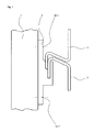
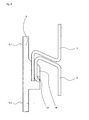
- Fig. 1 shows the facade system in a side view.
- the facade system has a substructure 1, essentially formed by vertical supporting profiles, as well as a first panel 2 and a second panel 3.
- the panels 2, 3 form the viewing elements of the façade system and, according to the invention, each have an upper fold section 4 and a lower fold section 5.
- the Abkantungsabitese 4, 5 can in this case both as simple or, as in Fig. 1 shown to be formed as two or more folds.
- At least one retaining element 6 is provided according to the invention, which in the present case is firmly connected to the substructure 1 via two attachment points 15.
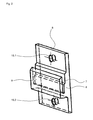
- the holding element 6 is in the Fig. 2 to 4 shown.
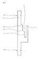
- the holding element 6 has as in Fig. 3 shown, a receiving portion 7, which in turn has a first edge 8 and a second edge 9.
- the first flank 8 forms the substructure-side region of the receiving section 7
- the second flank 9 forms the panel-side region of the receiving section 7.
- the first flank 8 has a gradation, through which, as in Fig. 3 represented, a first investment level 10 and a second investment level 11 are formed.
- the gradation of the first edge 8 is presently designed so that the distance between the first bearing plane 10 to the second edge 9 at least twice the material thickness of a panel 2, 3 corresponds and that the distance of the second bearing plane 11 to the second edge 9 at least the simple and less than twice the material thickness of a panel 2, 3 corresponds
- the panels 2, 3 are how Fig. 1 shows, arranged in the receiving portion 7 of the holding member 6, that the upper folded portion 4.2 of the first panel 2 between the second edge 9 and the second abutment plane 11 of the first edge 8 and the lower folded portion 5.3 of the second panel 3 between the first bearing plane 10 of first edge 8 and the upper folded portion 4.2 of the first panel 2 are arranged.
- the panels 2, 3 are suspended in the context of assembly of the facade system according to the invention in the holding element 6, wherein first the upper folded portion 4.2 of the first panel 2 is inserted into the receiving portion 7.
- the upper folded section 4.2 is thereby guided directly into the correct position between the second abutment plane 11 and the second flank 9 and thus at the same time the required space for receiving the lower fold section 5.3 of the second panel 3 is kept free.
- the gradation of the first edge 8 at the transition between the first bearing plane 10 and second abutment plane 11 a chamfer, through which the upper fold section 4.2 can be guided into the correct starting position.
- the hanging of the second panel 3 takes place in the present case, with the lower folded section 5.3 of the second panel 3 being received in the receiving section 7 between the first abutment plane 10 and the upper folded section 4.2 of the first panel 2.
- the deformation section 12 is presently provided by a deformation in the region of the fold in the manner of a dent and is preferably formed so that it overlaps both end sides of the support member 6. An undesired, horizontal movement of the first panel 2 is prevented by the deformation section 12 in the present case in such a way that a positive locking on both sides between the first panel 2 and the retaining element 6 is provided by the latter in the horizontal direction.
- first panel 2 described here can analogously also be applied to the second panel 3 as well as to further panels within the façade system according to the invention, in each case in conjunction with a further retaining element 6.
- deformation section 12 can optionally be provided already during the production of the respective panel 2, 3 or only after its arrangement in the retaining element 6.
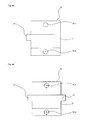
- the protruding portion 14 is according to Fig. 4a designed so that this one end face of the retaining element 6 übergragt and that this is at the same time on its underside by the deformation portion 12 of the first panel 2 behind gripped.
- the cantilever portion as shown in FIG Fig. 4b shown be designed so that it projects beyond both end sides of the holding element 6.
- the deformation section 12 is produced only after assembly, when the upper folded section 4.1 has assumed its end position in the receiving section 7, for example, by means of a pair of pliers, which is laterally bent next to the holding element 6 region of the folded section 4.1.
- a positive connection between the support member 6 and the first panel 2 can be provided by which an undesirable, vertical pulling out of the first panel 2 from the support member 6 can be prevented.
- Fig. 5 shows a particular embodiment in which the deformation portion 12 has already been made prior to assembly.
- the deformation section 12 is designed such that the total thickness of the panel 2 in the region of the deforming section 12 is the maximum opening width of the panel 2 Receiving section 7 is not surmounted.
- the arrangement of the panel 2 in the receiving portion 7 in this case preferably takes place such that the panel 2 is pushed from above into the receiving portion 7 until the deformation portion 12 has passed the projecting portion 14.
- the panel 2 is moved so far in the direction of the second flank 9, that the deformation portion 12 engages over the projection portion 14, and then further vertically lowered and brought into its final position.
- an assembly with prefabricated deformation section 12 can be ensured despite gradation of the first edge 8, in which case a vertical clearance between the deformation section 12 and 14 Auskragungsabites must be accepted.
- Fig. 6 shows a further embodiment of the facade system according to the invention with prefabricated deformation section 12, wherein the deformation section 12 of the first panel 2 deviating from the embodiment according to Fig. 5 However, in the end position rests directly on the protruding portion 14 of the retaining element 6. In this embodiment, a vertical clearance between the first panel 2 and retaining element 6 is avoided. According to the embodiment Fig. 6 For this purpose, the gradation of the first edge 8 is omitted.
- a holding element 6 of a further embodiment of the facade system is in Fig. 7 shown.
- the retaining element 6 has in this case a locking screw 16 which is arranged in a corresponding receptacle of the retaining element so that the locking screw 16, after the mounting of the retaining element 6 on the substructure 1, is accessible from the side of the substructure 1 and by means of a suitable tool (not shown) can be tightened.
- the arrangement of the locking screw 16 in the holding element 6 takes place here in such a way that the locking screw 16 passes through the first flank 8 and acts on the upper folded section 4 of the lower, first panel 2, whereby this in the holding element 6 between the locking screw and the opposite second flank 9 of the retaining element 6 is clamped.
- the first panel 2 is secured both against a vertical extension of the holding element 6, as well as against a horizontal displacement in the retaining element 6.
- the securing screw 16 can have, for example, a thread-side tip, through which a selective deformation of the upper folding section 4 of the first panel 2 and thus an optimized pull-out protection for the first panel 2 can be provided when the securing screw 16 is tightened.
- the receptacle for the locking screw 16 may be formed in the holding member 6 as a bore which passes through both the first edge 8, and the second edge 9 and which in the region of the first edge 8 has a thread into which the locking screw 16 is screwed ,
- a region in the second flank 9 is created as a further advantage, in which the upper folded section 4 of the first panel 2, under the action of the securing screw 16 and a resulting deformation, can be shaped in sections. In this way, an additional form-fit region between the panel 2 and the holding element 6 is created, by which the security against horizontal or vertical displacement of the panel 2 in the holding element 6 is additionally optimized.
Landscapes
- Engineering & Computer Science (AREA)
- Architecture (AREA)
- Civil Engineering (AREA)
- Structural Engineering (AREA)
- Finishing Walls (AREA)
Applications Claiming Priority (2)
| Application Number | Priority Date | Filing Date | Title |
|---|---|---|---|
| DE202014003094.4U DE202014003094U1 (de) | 2014-04-11 | 2014-04-11 | Fassadensystem |
| DE102014005329.6A DE102014005329B4 (de) | 2014-04-11 | 2014-04-11 | Fassadensystem |
Publications (3)
| Publication Number | Publication Date |
|---|---|
| EP2930286A2 true EP2930286A2 (fr) | 2015-10-14 |
| EP2930286A3 EP2930286A3 (fr) | 2015-12-23 |
| EP2930286B1 EP2930286B1 (fr) | 2017-06-14 |
Family
ID=52823433
Family Applications (1)
| Application Number | Title | Priority Date | Filing Date |
|---|---|---|---|
| EP15000992.6A Active EP2930286B1 (fr) | 2014-04-11 | 2015-04-08 | Système de façade |
Country Status (1)
| Country | Link |
|---|---|
| EP (1) | EP2930286B1 (fr) |
Cited By (4)
| Publication number | Priority date | Publication date | Assignee | Title |
|---|---|---|---|---|
| CN109537839A (zh) * | 2018-12-04 | 2019-03-29 | 华鼎建筑装饰工程有限公司 | 一种弧形铝单板和弧形铝单板安装结构 |
| WO2020084143A1 (fr) * | 2018-10-25 | 2020-04-30 | 3A Composites Gmbh | Système d'habillage de paroi, arrangement du système d'habillage et procédé pour le montage du système d'habillage |
| JP2022527034A (ja) * | 2019-04-11 | 2022-05-27 | シュイリン ドン | スプライス構造 |
| EP3822428B1 (fr) * | 2019-11-15 | 2023-06-07 | Rautaruukki Oyj | Panneau composite doté d'une structure en sandwich |
Citations (1)
| Publication number | Priority date | Publication date | Assignee | Title |
|---|---|---|---|---|
| DE202006018660U1 (de) | 2006-12-07 | 2007-04-26 | Weiser, Steffen | System zur Oberflächenbekleidung |
Family Cites Families (4)
| Publication number | Priority date | Publication date | Assignee | Title |
|---|---|---|---|---|
| FR1602051A (fr) * | 1968-10-18 | 1970-10-05 | ||
| GB2118988B (en) * | 1982-03-17 | 1985-09-04 | Hunter Douglas Ind Bv | Panelling and carriers therefor |
| DE202004020824U1 (de) * | 2004-08-03 | 2006-04-20 | Corus Bausysteme Gmbh | Halteelement für Bekleidungsprofile und Befestigungswerkzeug hierfür |
| NL1037431C2 (en) * | 2009-11-01 | 2011-05-03 | Faas Holding B V | Cladding system. |
-
2015
- 2015-04-08 EP EP15000992.6A patent/EP2930286B1/fr active Active
Patent Citations (1)
| Publication number | Priority date | Publication date | Assignee | Title |
|---|---|---|---|---|
| DE202006018660U1 (de) | 2006-12-07 | 2007-04-26 | Weiser, Steffen | System zur Oberflächenbekleidung |
Cited By (7)
| Publication number | Priority date | Publication date | Assignee | Title |
|---|---|---|---|---|
| WO2020084143A1 (fr) * | 2018-10-25 | 2020-04-30 | 3A Composites Gmbh | Système d'habillage de paroi, arrangement du système d'habillage et procédé pour le montage du système d'habillage |
| CN112912573A (zh) * | 2018-10-25 | 2021-06-04 | 3A复合材料有限公司 | 用于墙壁的覆层系统、覆层系统的布置以及安装覆层系统的方法 |
| US12276116B2 (en) | 2018-10-25 | 2025-04-15 | 3A Composites Gmbh | Cladding system for a wall, arrangement of tile cladding system and method for mounting the cladding system |
| CN109537839A (zh) * | 2018-12-04 | 2019-03-29 | 华鼎建筑装饰工程有限公司 | 一种弧形铝单板和弧形铝单板安装结构 |
| CN109537839B (zh) * | 2018-12-04 | 2022-08-16 | 华鼎建筑装饰工程有限公司 | 一种弧形铝单板和弧形铝单板安装结构 |
| JP2022527034A (ja) * | 2019-04-11 | 2022-05-27 | シュイリン ドン | スプライス構造 |
| EP3822428B1 (fr) * | 2019-11-15 | 2023-06-07 | Rautaruukki Oyj | Panneau composite doté d'une structure en sandwich |
Also Published As
| Publication number | Publication date |
|---|---|
| EP2930286A3 (fr) | 2015-12-23 |
| EP2930286B1 (fr) | 2017-06-14 |
Similar Documents
| Publication | Publication Date | Title |
|---|---|---|
| EP2619382B1 (fr) | Système de fixation pour éléments de façade, rails à profil d'insertion prévus à cet effet, et procédé de montage | |
| EP2930286B1 (fr) | Système de façade | |
| EP2530218B1 (fr) | Panneau de mur ou de plafond ainsi que le procédé d'habillage d'une partie de mur ou de plafond | |
| DE20206589U1 (de) | Verankerungsschraube mit einem Doppelkopf und einem Dreifachgewinde mit unterschiedlichen Gewindetiefen | |
| EP2844808B1 (fr) | Procédé de fabrication d'une cloison pour pose à sec | |
| EP3548412B1 (fr) | Dispositif de fixation et procédé permettant de fixer un élément de paroi dans une cabine d'ascenseur | |
| EP3365510B1 (fr) | Système destiné à l'habillage de murs, plafonds ou toits d'un corps de bâtiment | |
| EP3636844B1 (fr) | Cadre de construction en mur sec pour une porte coulissante | |
| DE102018126983A1 (de) | System zur Befestigung von Verkleidungselementen an Bauwerken, Bauwerk mit entsprechend befestigten Verkleidungselementen sowie Verfahren zur Montage und Demontage von Verkleidungselementen | |
| EP2851485A1 (fr) | Façade | |
| EP2933397B1 (fr) | Profil de liaison et panneau de construction préfabriqué à utiliser dans les cloisons sèches | |
| DE102014005329B4 (de) | Fassadensystem | |
| AT527298B1 (de) | Agraffenprofil und System umfassend Agraffenprofil und Agraffe | |
| DE202013004213U1 (de) | Profilleiste und Ständerwerk für eine im Trockenbau herzustellende Wand | |
| EP1647649A2 (fr) | Système de fixation de façades | |
| DE202014003094U1 (de) | Fassadensystem | |
| DE102010018593A1 (de) | Verbindungsbeschlag | |
| DE102019133839A1 (de) | Bauelement in Brandschutzausführung und Verfahren zur Montage eines Bauelementes | |
| DE102008055954A1 (de) | Klemmbefestigung von Profilen auf Stehfalz- oder Trapezblechen | |
| EP2660403A1 (fr) | Support pour matière isolante | |
| EP2447441B1 (fr) | Dispositif de fixation pour des éléments de bardage | |
| EP1783317B1 (fr) | Clip de fixation pour un profilé de support d'un dispositif d'occultation | |
| DE102007024994B4 (de) | Montageblech für eine Blockzarge | |
| DE102006004493B4 (de) | Führungsschienenbefestigung | |
| DE102015118156B4 (de) | Glashalter, damit versehener Brandschutzabschluss sowie Herstellverfahren |
Legal Events
| Date | Code | Title | Description |
|---|---|---|---|
| PUAI | Public reference made under article 153(3) epc to a published international application that has entered the european phase |
Free format text: ORIGINAL CODE: 0009012 |
|
| AK | Designated contracting states |
Kind code of ref document: A2 Designated state(s): AL AT BE BG CH CY CZ DE DK EE ES FI FR GB GR HR HU IE IS IT LI LT LU LV MC MK MT NL NO PL PT RO RS SE SI SK SM TR |
|
| AX | Request for extension of the european patent |
Extension state: BA ME |
|
| PUAL | Search report despatched |
Free format text: ORIGINAL CODE: 0009013 |
|
| AK | Designated contracting states |
Kind code of ref document: A3 Designated state(s): AL AT BE BG CH CY CZ DE DK EE ES FI FR GB GR HR HU IE IS IT LI LT LU LV MC MK MT NL NO PL PT RO RS SE SI SK SM TR |
|
| AX | Request for extension of the european patent |
Extension state: BA ME |
|
| RIC1 | Information provided on ipc code assigned before grant |
Ipc: E04F 13/12 20060101ALI20151119BHEP Ipc: E04F 13/08 20060101AFI20151119BHEP |
|
| 17P | Request for examination filed |
Effective date: 20160623 |
|
| RBV | Designated contracting states (corrected) |
Designated state(s): AL AT BE BG CH CY CZ DE DK EE ES FI FR GB GR HR HU IE IS IT LI LT LU LV MC MK MT NL NO PL PT RO RS SE SI SK SM TR |
|
| GRAP | Despatch of communication of intention to grant a patent |
Free format text: ORIGINAL CODE: EPIDOSNIGR1 |
|
| INTG | Intention to grant announced |
Effective date: 20161215 |
|
| GRAS | Grant fee paid |
Free format text: ORIGINAL CODE: EPIDOSNIGR3 |
|
| GRAA | (expected) grant |
Free format text: ORIGINAL CODE: 0009210 |
|
| AK | Designated contracting states |
Kind code of ref document: B1 Designated state(s): AL AT BE BG CH CY CZ DE DK EE ES FI FR GB GR HR HU IE IS IT LI LT LU LV MC MK MT NL NO PL PT RO RS SE SI SK SM TR |
|
| REG | Reference to a national code |
Ref country code: GB Ref legal event code: FG4D Free format text: NOT ENGLISH |
|
| REG | Reference to a national code |
Ref country code: CH Ref legal event code: EP Ref country code: AT Ref legal event code: REF Ref document number: 901101 Country of ref document: AT Kind code of ref document: T Effective date: 20170615 |
|
| REG | Reference to a national code |
Ref country code: IE Ref legal event code: FG4D Free format text: LANGUAGE OF EP DOCUMENT: GERMAN |
|
| REG | Reference to a national code |
Ref country code: DE Ref legal event code: R096 Ref document number: 502015001183 Country of ref document: DE |
|
| REG | Reference to a national code |
Ref country code: NL Ref legal event code: MP Effective date: 20170614 |
|
| REG | Reference to a national code |
Ref country code: LT Ref legal event code: MG4D |
|
| PG25 | Lapsed in a contracting state [announced via postgrant information from national office to epo] |
Ref country code: FI Free format text: LAPSE BECAUSE OF FAILURE TO SUBMIT A TRANSLATION OF THE DESCRIPTION OR TO PAY THE FEE WITHIN THE PRESCRIBED TIME-LIMIT Effective date: 20170614 Ref country code: LT Free format text: LAPSE BECAUSE OF FAILURE TO SUBMIT A TRANSLATION OF THE DESCRIPTION OR TO PAY THE FEE WITHIN THE PRESCRIBED TIME-LIMIT Effective date: 20170614 Ref country code: GR Free format text: LAPSE BECAUSE OF FAILURE TO SUBMIT A TRANSLATION OF THE DESCRIPTION OR TO PAY THE FEE WITHIN THE PRESCRIBED TIME-LIMIT Effective date: 20170915 Ref country code: NO Free format text: LAPSE BECAUSE OF FAILURE TO SUBMIT A TRANSLATION OF THE DESCRIPTION OR TO PAY THE FEE WITHIN THE PRESCRIBED TIME-LIMIT Effective date: 20170914 Ref country code: HR Free format text: LAPSE BECAUSE OF FAILURE TO SUBMIT A TRANSLATION OF THE DESCRIPTION OR TO PAY THE FEE WITHIN THE PRESCRIBED TIME-LIMIT Effective date: 20170614 |
|
| PG25 | Lapsed in a contracting state [announced via postgrant information from national office to epo] |
Ref country code: LV Free format text: LAPSE BECAUSE OF FAILURE TO SUBMIT A TRANSLATION OF THE DESCRIPTION OR TO PAY THE FEE WITHIN THE PRESCRIBED TIME-LIMIT Effective date: 20170614 Ref country code: RS Free format text: LAPSE BECAUSE OF FAILURE TO SUBMIT A TRANSLATION OF THE DESCRIPTION OR TO PAY THE FEE WITHIN THE PRESCRIBED TIME-LIMIT Effective date: 20170614 Ref country code: NL Free format text: LAPSE BECAUSE OF FAILURE TO SUBMIT A TRANSLATION OF THE DESCRIPTION OR TO PAY THE FEE WITHIN THE PRESCRIBED TIME-LIMIT Effective date: 20170614 Ref country code: SE Free format text: LAPSE BECAUSE OF FAILURE TO SUBMIT A TRANSLATION OF THE DESCRIPTION OR TO PAY THE FEE WITHIN THE PRESCRIBED TIME-LIMIT Effective date: 20170614 Ref country code: BG Free format text: LAPSE BECAUSE OF FAILURE TO SUBMIT A TRANSLATION OF THE DESCRIPTION OR TO PAY THE FEE WITHIN THE PRESCRIBED TIME-LIMIT Effective date: 20170914 |
|
| PG25 | Lapsed in a contracting state [announced via postgrant information from national office to epo] |
Ref country code: EE Free format text: LAPSE BECAUSE OF FAILURE TO SUBMIT A TRANSLATION OF THE DESCRIPTION OR TO PAY THE FEE WITHIN THE PRESCRIBED TIME-LIMIT Effective date: 20170614 Ref country code: CZ Free format text: LAPSE BECAUSE OF FAILURE TO SUBMIT A TRANSLATION OF THE DESCRIPTION OR TO PAY THE FEE WITHIN THE PRESCRIBED TIME-LIMIT Effective date: 20170614 Ref country code: RO Free format text: LAPSE BECAUSE OF FAILURE TO SUBMIT A TRANSLATION OF THE DESCRIPTION OR TO PAY THE FEE WITHIN THE PRESCRIBED TIME-LIMIT Effective date: 20170614 Ref country code: SK Free format text: LAPSE BECAUSE OF FAILURE TO SUBMIT A TRANSLATION OF THE DESCRIPTION OR TO PAY THE FEE WITHIN THE PRESCRIBED TIME-LIMIT Effective date: 20170614 |
|
| PG25 | Lapsed in a contracting state [announced via postgrant information from national office to epo] |
Ref country code: IS Free format text: LAPSE BECAUSE OF FAILURE TO SUBMIT A TRANSLATION OF THE DESCRIPTION OR TO PAY THE FEE WITHIN THE PRESCRIBED TIME-LIMIT Effective date: 20171014 Ref country code: ES Free format text: LAPSE BECAUSE OF FAILURE TO SUBMIT A TRANSLATION OF THE DESCRIPTION OR TO PAY THE FEE WITHIN THE PRESCRIBED TIME-LIMIT Effective date: 20170614 Ref country code: SM Free format text: LAPSE BECAUSE OF FAILURE TO SUBMIT A TRANSLATION OF THE DESCRIPTION OR TO PAY THE FEE WITHIN THE PRESCRIBED TIME-LIMIT Effective date: 20170614 Ref country code: IT Free format text: LAPSE BECAUSE OF FAILURE TO SUBMIT A TRANSLATION OF THE DESCRIPTION OR TO PAY THE FEE WITHIN THE PRESCRIBED TIME-LIMIT Effective date: 20170614 Ref country code: PL Free format text: LAPSE BECAUSE OF FAILURE TO SUBMIT A TRANSLATION OF THE DESCRIPTION OR TO PAY THE FEE WITHIN THE PRESCRIBED TIME-LIMIT Effective date: 20170614 |
|
| REG | Reference to a national code |
Ref country code: DE Ref legal event code: R097 Ref document number: 502015001183 Country of ref document: DE |
|
| PLBE | No opposition filed within time limit |
Free format text: ORIGINAL CODE: 0009261 |
|
| STAA | Information on the status of an ep patent application or granted ep patent |
Free format text: STATUS: NO OPPOSITION FILED WITHIN TIME LIMIT |
|
| PG25 | Lapsed in a contracting state [announced via postgrant information from national office to epo] |
Ref country code: DK Free format text: LAPSE BECAUSE OF FAILURE TO SUBMIT A TRANSLATION OF THE DESCRIPTION OR TO PAY THE FEE WITHIN THE PRESCRIBED TIME-LIMIT Effective date: 20170614 |
|
| 26N | No opposition filed |
Effective date: 20180315 |
|
| PG25 | Lapsed in a contracting state [announced via postgrant information from national office to epo] |
Ref country code: SI Free format text: LAPSE BECAUSE OF FAILURE TO SUBMIT A TRANSLATION OF THE DESCRIPTION OR TO PAY THE FEE WITHIN THE PRESCRIBED TIME-LIMIT Effective date: 20170614 |
|
| PG25 | Lapsed in a contracting state [announced via postgrant information from national office to epo] |
Ref country code: MT Free format text: LAPSE BECAUSE OF FAILURE TO SUBMIT A TRANSLATION OF THE DESCRIPTION OR TO PAY THE FEE WITHIN THE PRESCRIBED TIME-LIMIT Effective date: 20170614 |
|
| PG25 | Lapsed in a contracting state [announced via postgrant information from national office to epo] |
Ref country code: MC Free format text: LAPSE BECAUSE OF FAILURE TO SUBMIT A TRANSLATION OF THE DESCRIPTION OR TO PAY THE FEE WITHIN THE PRESCRIBED TIME-LIMIT Effective date: 20170614 |
|
| REG | Reference to a national code |
Ref country code: CH Ref legal event code: PL |
|
| REG | Reference to a national code |
Ref country code: BE Ref legal event code: MM Effective date: 20180430 |
|
| REG | Reference to a national code |
Ref country code: IE Ref legal event code: MM4A |
|
| PG25 | Lapsed in a contracting state [announced via postgrant information from national office to epo] |
Ref country code: LU Free format text: LAPSE BECAUSE OF NON-PAYMENT OF DUE FEES Effective date: 20180408 |
|
| PG25 | Lapsed in a contracting state [announced via postgrant information from national office to epo] |
Ref country code: LI Free format text: LAPSE BECAUSE OF NON-PAYMENT OF DUE FEES Effective date: 20180430 Ref country code: CH Free format text: LAPSE BECAUSE OF NON-PAYMENT OF DUE FEES Effective date: 20180430 Ref country code: BE Free format text: LAPSE BECAUSE OF NON-PAYMENT OF DUE FEES Effective date: 20180430 |
|
| PG25 | Lapsed in a contracting state [announced via postgrant information from national office to epo] |
Ref country code: FR Free format text: LAPSE BECAUSE OF NON-PAYMENT OF DUE FEES Effective date: 20180430 Ref country code: IE Free format text: LAPSE BECAUSE OF NON-PAYMENT OF DUE FEES Effective date: 20180408 |
|
| GBPC | Gb: european patent ceased through non-payment of renewal fee |
Effective date: 20190408 |
|
| PG25 | Lapsed in a contracting state [announced via postgrant information from national office to epo] |
Ref country code: GB Free format text: LAPSE BECAUSE OF NON-PAYMENT OF DUE FEES Effective date: 20190408 |
|
| PG25 | Lapsed in a contracting state [announced via postgrant information from national office to epo] |
Ref country code: TR Free format text: LAPSE BECAUSE OF FAILURE TO SUBMIT A TRANSLATION OF THE DESCRIPTION OR TO PAY THE FEE WITHIN THE PRESCRIBED TIME-LIMIT Effective date: 20170614 |
|
| PG25 | Lapsed in a contracting state [announced via postgrant information from national office to epo] |
Ref country code: PT Free format text: LAPSE BECAUSE OF FAILURE TO SUBMIT A TRANSLATION OF THE DESCRIPTION OR TO PAY THE FEE WITHIN THE PRESCRIBED TIME-LIMIT Effective date: 20170614 |
|
| PG25 | Lapsed in a contracting state [announced via postgrant information from national office to epo] |
Ref country code: CY Free format text: LAPSE BECAUSE OF FAILURE TO SUBMIT A TRANSLATION OF THE DESCRIPTION OR TO PAY THE FEE WITHIN THE PRESCRIBED TIME-LIMIT Effective date: 20170614 Ref country code: HU Free format text: LAPSE BECAUSE OF FAILURE TO SUBMIT A TRANSLATION OF THE DESCRIPTION OR TO PAY THE FEE WITHIN THE PRESCRIBED TIME-LIMIT; INVALID AB INITIO Effective date: 20150408 Ref country code: MK Free format text: LAPSE BECAUSE OF NON-PAYMENT OF DUE FEES Effective date: 20170614 |
|
| PG25 | Lapsed in a contracting state [announced via postgrant information from national office to epo] |
Ref country code: AL Free format text: LAPSE BECAUSE OF FAILURE TO SUBMIT A TRANSLATION OF THE DESCRIPTION OR TO PAY THE FEE WITHIN THE PRESCRIBED TIME-LIMIT Effective date: 20170614 |
|
| PGFP | Annual fee paid to national office [announced via postgrant information from national office to epo] |
Ref country code: AT Payment date: 20220419 Year of fee payment: 8 |
|
| REG | Reference to a national code |
Ref country code: AT Ref legal event code: MM01 Ref document number: 901101 Country of ref document: AT Kind code of ref document: T Effective date: 20230408 |
|
| PG25 | Lapsed in a contracting state [announced via postgrant information from national office to epo] |
Ref country code: AT Free format text: LAPSE BECAUSE OF NON-PAYMENT OF DUE FEES Effective date: 20230408 |
|
| PGFP | Annual fee paid to national office [announced via postgrant information from national office to epo] |
Ref country code: DE Payment date: 20250611 Year of fee payment: 11 |
|
| REG | Reference to a national code |
Ref country code: DE Ref legal event code: R082 Ref document number: 502015001183 Country of ref document: DE Representative=s name: WEIHRAUCH, FRANK, DR., DE |