EP2930460A1 - Projectile à vol supersonique pour canon à tube lisse - Google Patents
Projectile à vol supersonique pour canon à tube lisse Download PDFInfo
- Publication number
- EP2930460A1 EP2930460A1 EP15160232.3A EP15160232A EP2930460A1 EP 2930460 A1 EP2930460 A1 EP 2930460A1 EP 15160232 A EP15160232 A EP 15160232A EP 2930460 A1 EP2930460 A1 EP 2930460A1
- Authority
- EP
- European Patent Office
- Prior art keywords
- projectile
- tail
- cone
- cylindrical
- projectile according
- Prior art date
- Legal status (The legal status is an assumption and is not a legal conclusion. Google has not performed a legal analysis and makes no representation as to the accuracy of the status listed.)
- Granted
Links
Images

Classifications
-
- F—MECHANICAL ENGINEERING; LIGHTING; HEATING; WEAPONS; BLASTING
- F42—AMMUNITION; BLASTING
- F42B—EXPLOSIVE CHARGES, e.g. FOR BLASTING, FIREWORKS, AMMUNITION
- F42B10/00—Means for influencing, e.g. improving, the aerodynamic properties of projectiles or missiles; Arrangements on projectiles or missiles for stabilising, steering, range-reducing, range-increasing or fall-retarding
- F42B10/02—Stabilising arrangements
Definitions
- the technical field of the invention is that of projectiles with supersonic flight fired by a smooth-tube gun, and in particular that of the projectiles fired by the tank guns with a caliber of between 90 mm and 130 mm.
- the supersonic flight projectiles for smooth tube gun are generally stabilized by a tail.
- projectiles Two main types of projectiles are known for smooth-arm weapons: sub-calibrated projectiles (or arrow projectiles) and caliber projectiles.
- the sub-calibrated projectiles have a bar whose diameter is much smaller than the caliber of the tube, which bar is pulled using a caliper shoe.
- These projectiles comprise a stabilizer formed of several radial fins.
- Projectiles with caliber are most often explosive projectiles. They have a body that is extended at its rear by a tail tail with a stabilizer stabilizer.
- Exercise projectiles are also known to be associated with each type of war projectile.
- a caliber exercise projectile has almost the same proportions as an explosive projectile but it is made of inert material. It carries a rear tail substantially to the diameter of the projectile body and located at a substantial distance from the body. The length of the projectile, the belt to the rear of the empennage, is thus substantially half of the total length of the projectile. The scope of this projectile is the same as that of the explosive projectile.
- Licences US2006 / 065149 and US5328130 also describe shots drawn by smooth tube and whose stabilization is provided by a rear cylindrical stabilizer which carries a split collar to give a moderate rotation to compensate for asymmetries.
- the feathered projectiles with caliber as described by the patent DE4132659 have a long tail tail that penetrates deeply into the case containing the propellant charge. These projectiles reduce the mass of propellant powder that can be housed in the case. The length of the empennage also hinders the placement of the projectile in a loaded socket and impose either a loading of the case from the rear and after mounting the projectile, or a load in two burdens, a first burden attached to the projectile and a second burden located in the holster.
- the invention can thus be used more particularly to produce an exercise projectile.
- the subject of the invention is a projectile with supersonic flight that can be fired by a smooth-tube gun, a projectile comprising a body of the caliber of the barrel tube and an aerodynamic stabilization means disposed behind the body, a projectile characterized in that the means of aerodynamic stabilization is formed by a cone whose largest diameter is substantially equal to the diameter of the body, the cone being connected to the body by a cylindrical surface, the body having an annular rear face perpendicular to the axis of the projectile and on which connects the cylindrical surface, the height of the annular face and the length of the cylindrical surface being defined so as to ensure separation of the aerodynamic flow behind the annular face, and then the bonding of this flow directly on the conical stabilizing element .
- the ratio between the length of the cylindrical surface and the height of the annular rear face will be between 1.5 and 3.5.
- the length of the tail tail formed by the cone and the cylindrical bearing may be less than 40% of the total length of the projectile.
- the cone may have an apex angle between 10 ° and 40 °.
- the cone may comprise a cylindrical rear portion followed by a conical necking.
- the cylindrical scope may comprise radial bores connecting the outer surface of the cylindrical seat with a volume internal to the tail tail.
- the tail tail may be integral with a ring, the diameter of the body and having the annular rear face, which ring will be a rear portion of the body and which will attach to a front portion of the body.
- the front part of the body may be made of steel and the tail tail and the rear part of the body may be made of aluminum alloy.
- the projectile according to the invention may constitute an inert exercise projectile, or an explosive projectile.
- a projectile 1 fired by a smooth tube gun comprises a body 2 to the caliber of the tube and aerodynamic stabilization means 3 disposed behind the body 2.
- the projectile 1 is a projectile d inert exercise.
- the socket according to the caliber may be metallic or combustible.
- This bushing of conventional type is not part of the invention and is not shown.
- the aerodynamic stabilization means 3 is formed by a cone of revolution whose largest diameter D3 is substantially equal to the diameter D2 of the body 2.
- the diameter D3 may be slightly less than the diameter D2 but the diameter D3 will be chosen sufficient for the recollement of the aerodynamic flow is done on the cone.
- the cone 3 is connected to the body 2 by a cylindrical bearing surface 4 of diameter D1.
- the body 2 has an annular rear face 5 which is perpendicular to the axis 6 of the projectile and on which is connected the cylindrical seat 4.
- the cone 3 has an apex angle of between 10 ° and 40 ° (and preferably between 15 ° and 30 °). This choice of the angle of the cone makes it possible to ensure a sufficient increase of the aerodynamic pressure on the cone.
- the cone 3 may carry on its periphery grooves or notches 16 which will be inclined relative to the axis 6 of the projectile. Such an arrangement will allow (in known manner) a rotation of the projectile 1 on trajectory which improves the stability and avoids a roll-pitch resonance phenomenon.
- the assembly constituted by the cone 3 and the cylindrical bearing surface 4 constitutes a tail tail 7 which has a length L1.
- the empennage tail 7 is secured to a ring 8 of the caliber of the body 2 and which carries the annular rear face 5.
- the empennage tail 7 and the ring 8 are formed here in one piece.
- the ring 8 constitutes a rear portion of the body 2 and it is fixed to a front portion 2a of the body 2 by a thread 9.
- the body 2 also carries a sealing belt 10.
- the front portion 2a of the body 2 is made of steel while the empennage tail 7 and the rear portion 8 of the body are made of aluminum alloy. This results in a positioning of the center of gravity C of the projectile substantially halfway between the front and the rear of the projectile 1.
- the empennage tail 7 comprises an internal cylindrical volume 11 which can receive, for example, a tracer (not shown).
- the bonding of the flow then intervenes directly on the cone 3 (of angle between 10 ° and 40 °) and makes it possible to exert on it the greatest possible pressure, by recompression of the flow, thus ensuring a maximum stabilizing efficiency of the cone 3.
- the pressure at the level of the impact on the cone 3 is multiplied approximately by 2 with respect to the initial pressure at the annular face 5.
- This strong pressure exerted on the stabilizing cone 3 causes a stabilizing effect of the cone much higher than that which would be obtained with a projectile of the same geometry but in which there would be a more progressive variation of the aerodynamic flow without detachment of the boundary layer (for example with a projectile having a conical profile surface between the gauge body and the cylindrical bearing surface 4).
- the projectile may have a length L1 of the tail tail 7 which is less than 40% of the total length L of the projectile.
- a projectile will be stable (empirically) if its static margin is about one caliber.
- the skilled person will define the geometry of the projectile providing stability by acting on the position of the center of gravity C which can be positioned in front of the projectile by adopting a material for the front portion 2a of the body which will be denser than the material of the empennage tail 7 and the rear portion 8 of the body.
- a ballast may be attached to the front of the body to advance the center of gravity.
- the focus of the aerodynamic forces will be positioned by playing both on the height H of the step formed by the annular rear face 5 (half gap between D1 and D2), the length L3 of the cylindrical scope (retaining the relative proportions between H and L3 mentioned previously) and on the angle of the cone 3.
- the essential point is that the ratio between the length L3 of the cylindrical bearing surface 4 and the height H of the rear face 5 is between 1.5 and 3.5 and that the angle of the cone 3 is between 10 ° and 40 °. °.
- the figure 2 shows another embodiment of an exercise projectile according to the invention, projectile which differs from the previous one in that the cone 3 has a rear portion 17 which is cylindrical and which is followed by a narrowing of conical base 13.
- This device allows in the case of an exercise projectile to adjust the aerodynamic drag of the projectile to ensure better ballistic similarity.
- the cone 3 may carry peripheral notches (not shown).
- the internal volume 11 at the cone 3 communicates with the external surface of the cylindrical seat 4 by radial bores 12.
- the propellant gases that enter the internal volume 11 can radially out of this volume through the holes 12.
- the internal volume 11 of the tail tail communicates here with a cavity 14 internal to the body 2 of the projectile.
- This cavity makes it possible to receive a tracer or an impact marking load (not shown).
- the figure 3 shows another embodiment of the invention wherein the projectile 1 is an explosive projectile. Note that the length L2 of the body 2 of the projectile is longer than that of the exercise projectiles described above.
- the body 2 carries the belt 10 and also a front guide ring 15.
- the internal structure of the body 2 is not shown because it is not part of the object of the present invention. It is similar to that of known projectiles and may for example comprise an explosive charge associated with a hollow charge coating.
- the body 2 has an annular rear face 5 on which the tail tail 7 has the cylindrical bearing surface 4.
- the empennage tail 7 may thus have a reduced length L1 which does not exceed 40% of the total length of the tail. projectile and is virtually non-intrusive in the propellant charge of the bushing.
Landscapes
- Physics & Mathematics (AREA)
- Fluid Mechanics (AREA)
- Engineering & Computer Science (AREA)
- General Engineering & Computer Science (AREA)
- Toys (AREA)
Abstract
Description
- Le domaine technique de l'invention est celui des projectiles à vol supersonique tirables par un canon à tube lisse, et en particulier celui des projectiles tirés par les canons de char d'un calibre compris entre 90 mm et 130 mm.
- Les projectiles à vol supersonique pour canon à tube lisse sont généralement stabilisés par un empennage.
- On connaît deux types principaux de projectiles pour les armes à tube lisse : les projectiles sous-calibrés (ou projectiles flèches) et les projectiles au calibre.
- Les projectiles sous-calibrés comportent un barreau dont le diamètre est bien inférieur au calibre du tube, barreau qui est tiré à l'aide d'un sabot au calibre. Ces projectiles comportent un empennage formé de plusieurs ailettes radiales.
- Les projectiles au calibre sont le plus souvent des projectiles explosifs. Ils ont un corps qui est prolongé à sa partie arrière par une queue d'empennage portant un empennage stabilisateur.
- On connaît aussi des projectiles d'exercice qui sont associables à chaque type de projectile de guerre.
- On connaît ainsi, en particulier par le brevet
EP1750081 , un projectile flèche d'exercice dont le corps sous-calibré porte à sa partie arrière un cône stabilisateur. Le cône assure tout à la fois une stabilisation aérodynamique du projectile et un freinage de celui-ci sur trajectoire, permettant de réduire la portée. Le cône a un diamètre supérieur à celui du corps sous-calibré. - On connaît aussi par le brevet
DE4132659 un projectile d'exercice au calibre. Ce projectile a pratiquement les mêmes proportions qu'un projectile explosif mais il est réalisé en matériau inerte. Il porte un empennage arrière sensiblement au diamètre du corps de projectile et situé à une distance importante du corps. La longueur du projectile, de la ceinture jusqu'à l'arrière de l'empennage, est ainsi sensiblement la moitié de la longueur totale du projectile. La portée de ce projectile est la même que celle du projectile explosif. - On connaît enfin par le brevet
WO2013150095 un projectile d'exercice qui comporte une jupe arrière cylindrique sensiblement au calibre. Ce projectile présente l'avantage d'avoir un coût réduit. Ses performances de stabilité sont cependant insuffisantes et nécessitent un positionnement du centre de gravité très en avant du projectile. La jupe présente un coefficient aérodynamique (Cx) important qui freine le projectile sur trajectoire. - Les brevets
US2006/065149 etUS5328130 décrivent eux aussi des projectiles tirés par tube lisse et dont la stabilisation est assurée par un stabilisateur cylindrique arrière qui porte une collerette fendue permettant de donner une rotation modérée permettant de compenser les dissymétries. - Ces projectiles nécessitent également pour être stables un positionnement de leur centre de gravité très en avant du projectile.
- Les projectiles empennés au calibre tels que décrit par le brevet
DE4132659 comportent une queue d'empennage de grande longueur qui pénètre profondément dans l'étui renfermant la charge propulsive. Ces projectiles réduisent la masse de poudre propulsive qu'il est possible de loger dans l'étui. La longueur de l'empennage gêne par ailleurs la mise en place du projectile dans une douille chargée et imposent, soit un chargement de l'étui par l'arrière et après montage du projectile, soit un chargement en deux fardeaux, un premier fardeau attaché au projectile et un second fardeau situé dans l'étui. - Les projectiles décrits par les brevets
WO2013150095 ,US2006/065149 etUS5328130 ont une longueur réduite mais leur stabilité sur trajectoire est faible et ce concept de projectiles est limité à la réalisation de projectiles d'exercice. - On connaît enfin par le brevet
US463922 un projectile gyrostabilisé qui est mis en rotation dans le tube par un passage des gaz propulsifs vers l'avant du projectile, dans des sillons périphériques. Ce projectile n'est pas stabilisé aérodynamiquement mais gyrostabilisé et l'orientation des fentes aura pour effet de freiner sa rotation sur trajectoire, réduisant encore plus sa stabilité. - C'est le but de l'invention que de proposer un projectile pour canon lisse comportant des moyens de stabilisation faiblement intrusifs dans le chargement propulsif mais ayant pourtant une excellente stabilité sur trajectoire.
- C'est un autre but de l'invention que de proposer une architecture de projectile simple et peu coûteuse. L'invention peut ainsi plus particulièrement être mise en oeuvre pour réaliser un projectile d'exercice.
- Ainsi l'invention a pour objet un projectile à vol supersonique tirable par un canon à tube lisse, projectile comportant un corps au calibre du tube du canon et un moyen de stabilisation aérodynamique disposé en arrière du corps, projectile caractérisé en ce que le moyen de stabilisation aérodynamique est formé par un cône dont le plus grand diamètre est sensiblement égal au diamètre du corps, le cône étant relié au corps par une portée cylindrique, le corps comportant une face arrière annulaire perpendiculaire à l'axe du projectile et sur laquelle se raccorde la portée cylindrique, la hauteur de la face annulaire et la longueur de la portée cylindrique étant définies de façon à assurer un décollement de l'écoulement aérodynamique en arrière de la face annulaire, puis le recollement de cet écoulement directement sur l'élément stabilisateur conique.
- Avantageusement, le rapport entre la longueur de la portée cylindrique et la hauteur de la face arrière annulaire sera compris entre 1,5 et 3,5.
- La longueur de la queue d'empennage formée par le cône et la portée cylindrique pourra être inférieure à 40% de la longueur totale du projectile.
- Le cône pourra avoir un angle au sommet compris entre 10° et 40°.
- Selon un mode de réalisation, le cône pourra comporter une partie arrière cylindrique suivie d'un rétreint conique.
- La portée cylindrique pourra comporter des perçages radiaux reliant la surface externe de la portée cylindrique avec un volume interne à la queue d'empennage.
- Selon un mode particulier de réalisation, la queue d'empennage pourra être solidaire d'une bague, au diamètre du corps et comportant la face arrière annulaire, bague qui constituera une partie arrière du corps et qui se fixera à une partie avant du corps.
- La partie avant du corps pourra être réalisée en acier et la queue d'empennage et la partie arrière du corps pourront être réalisées en alliage d'aluminium.
- Le projectile selon l'invention pourra constituer un projectile d'exercice inerte, ou bien un projectile explosif.
- L'invention sera mieux comprise à la lecture de la description qui va suivre de modes particuliers de réalisation, description faite en référence aux dessins annexés et dans lesquels :
- La
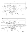
figure 1 montre en coupe longitudinale un projectile selon un mode de réalisation de l'invention, - La
figure 2 montre en coupe longitudinale un projectile selon un autre mode de réalisation de l'invention, - La
figure 3 montre en coupe longitudinale partielle un projectile selon un autre mode de réalisation de l'invention. - En se reportant à la
figure 1 , un projectile 1 tirable par un canon à tube lisse selon l'invention comporte un corps 2 au calibre du tube et un moyen de stabilisation aérodynamique 3 disposé en arrière du corps 2. Suivant le mode de réalisation représenté le projectile 1 est un projectile d'exercice inerte. - Bien entendu ce projectile est solidaire d'une douille renfermant une charge propulsive pour constituer une munition. La douille selon le calibre pourra être métallique ou combustible. Cette douille de type classique ne fait pas partie de l'invention et n'est donc pas représentée.
- Le moyen de stabilisation aérodynamique 3 est formé par un cône de révolution dont le plus grand diamètre D3 est sensiblement égal au diamètre D2 du corps 2.
- Le diamètre D3 peut être légèrement inférieur au diamètre D2 mais le diamètre D3 sera choisi suffisant pour que le recollement de l'écoulement aérodynamique se fasse sur le cône.
- Le cône 3 est relié au corps 2 par une portée cylindrique 4 de diamètre D1.
- Le corps 2 comporte une face arrière annulaire 5 qui est perpendiculaire à l'axe 6 du projectile et sur laquelle se raccorde la portée cylindrique 4.
- Le cône 3 a un angle au sommet compris entre 10° et 40° (et de préférence compris entre 15° et 30°). Ce choix de l'angle du cône permet d'assurer un accroissement suffisant de la pression aérodynamique sur le cône. Le cône 3 pourra porter sur sa périphérie des rainures ou encoches 16 qui seront inclinées par rapport à l'axe 6 du projectile. Une telle disposition permettra (de façon connue) une mise en rotation du projectile 1 sur trajectoire ce qui améliore la stabilité et permet d'éviter un phénomène de résonance roulis-tangage.
- L'ensemble constitué par le cône 3 et la portée cylindrique 4 constitue une queue d'empennage 7 qui a une longueur L1. La longueur totale du projectile est L et la longueur du corps est L2 (L= L1 + L2).
- Selon le mode de réalisation qui est représenté ici, la queue d'empennage 7 est solidaire d'une bague 8 au calibre du corps 2 et qui porte la face arrière annulaire 5. La queue d'empennage 7 et la bague 8 sont formées ici de façon monobloc. La bague 8 constitue une partie arrière du corps 2 et elle se fixe à une partie avant 2a du corps 2 par un filetage 9.
- Le corps 2 porte par ailleurs une ceinture d'étanchéité 10.
- La partie avant 2a du corps 2 est réalisée en acier tandis que la queue d'empennage 7 et la partie arrière 8 du corps sont réalisées en alliage d'aluminium. Il en résulte un positionnement du centre de gravité C du projectile sensiblement à mi-distance de l'avant et de l'arrière du projectile 1.
- La queue d'empennage 7 comporte un volume interne 11 cylindrique qui pourra recevoir par exemple un traceur (non représenté).
- On définira le projectile de telle sorte que le rapport entre la longueur L3 de la portée cylindrique 4 et la hauteur H de la face arrière 5 (H=(D2-D1)/2) soit compris entre 1,5 et 3,5 (bornes incluses) suivant le régime de vol du projectile. Soit en d'autres termes : 1,5 x H ≤ L3 ≤ 3,5 x H
- La combinaison de la présence d'une face arrière annulaire 5, de hauteur H suffisante, suivie d'une portée cylindrique 4 de longueur L3 adaptée conduit, en régime de vol supersonique, au décollement de l'écoulement aérodynamique au niveau de la « marche descendante » constituée par le passage du diamètre D2 au diamètre D1, en arrière de la face annulaire 5, puis au recollement de l'écoulement directement sur l'élément stabilisateur conique 3.
- Cette combinaison permet d'éviter le recollement de l'écoulement sur la portée cylindrique 4.
- Le recollement de l'écoulement intervient alors directement sur le cône 3 (d'angle compris entre 10° et 40°) et permet d'exercer sur celui-ci la plus grande pression possible, par recompression de l'écoulement, assurant ainsi une efficacité stabilisatrice maximale du cône 3.
- A titre d'exemple : la pression au niveau de l'impact sur le cône 3 est multipliée environ par 2 par rapport à la pression initiale au niveau de la face annulaire 5.
- Cette forte pression exercée sur le cône stabilisateur 3 entraîne un effet stabilisateur du cône bien supérieur à celui qui serait obtenu avec un projectile de même géométrie mais dans lequel il y aurait une variation plus progressive de l'écoulement aérodynamique sans décollement de la couche limite (par exemple avec un projectile comportant une surface à profil conique entre le corps au calibre et la portée cylindrique 4).
- Il en résulte la possibilité, à calibre égal, de réaliser un projectile bien plus court que les projectiles selon l'art antérieur.
- Ainsi le projectile peut avoir une longueur L1 de la queue d'empennage 7 qui est inférieure à 40% de la longueur totale L du projectile.
- D'une façon classique la stabilité d'un projectile empenné supersonique est conditionnée par la marge statique de ce projectile, c'est à dire la distance entre le centre de gravité C du projectile et le foyer des efforts aérodynamique qui s'exercent sur lui en vol.
- Un projectile sera stable (de façon empirique) si sa marge statique est d'environ un calibre.
- L'Homme du Métier définira la géométrie du projectile assurant la stabilité en jouant sur la position du centre de gravité C qui peut être positionné en avant du projectile en adoptant un matériau pour la partie avant 2a du corps qui sera plus dense que le matériau de la queue d'empennage 7 et de la partie arrière 8 du corps. Un lest pourra éventuellement être fixé à la partie avant du corps pour avancer le centre de gravité.
- Le foyer des efforts aérodynamiques sera positionné en jouant à la fois sur la hauteur H de la marche formée par la face arrière annulaire 5 (demi écart entre D1 et D2), sur la longueur L3 de la portée cylindrique (en conservant les proportions relatives entre H et L3 mentionnées précédemment) et sur l'angle du cône 3.
- L'Homme du Métier pourra utiliser des outils de modélisation des écoulements supersoniques pour définir les géométries de la face arrière 5 et de la queue d'empennage 7.
- L'essentiel est que le rapport entre la longueur L3 de la portée cylindrique 4 et la hauteur H de la face arrière 5 soit compris entre 1,5 et 3,5 et que l'angle du cône 3 soit compris entre 10° et 40°.
- La
figure 2 montre un autre mode de réalisation d'un projectile d'exercice selon l'invention, projectile qui diffère du précédent en ce que le cône 3 comporte une partie arrière 17 qui est cylindrique et qui est suivie d'un rétreint de culot conique 13. Ce dispositif permet dans le cas d'un projectile d'exercice d'ajuster la traînée aérodynamique du projectile afin d'assurer une meilleure similitude balistique. Comme dans le mode précédent, le cône 3 pourra porter des encoches périphériques (non représentées). - Suivant ce mode de réalisation, le volume interne 11 au cône 3 communique avec la surface externe de la portée cylindrique 4 par des perçages radiaux 12. Lors du tir du projectile 1, les gaz propulsifs qui entrent dans le volume interne 11 peuvent sortir radialement de ce volume au travers des perçages 12. La pression s'équilibre donc entre la surface externe de la portée cylindrique 4 et le volume interne 11.
- Par ailleurs le volume interne 11 de la queue d'empennage communique ici avec une cavité 14 interne au corps 2 du projectile. Cette cavité permet de recevoir un traceur ou une charge de marquage d'impact (non représentée).
- Les proportions relatives de la queue d'empennage 7 et du corps sont les mêmes que celles décrites précédemment.
- La
figure 3 montre un autre mode de réalisation de l'invention dans lequel le projectile 1 est un projectile explosif. On remarque que la longueur L2 du corps 2 du projectile est plus longue que celle des projectiles d'exercice décrits précédemment. Le corps 2 porte la ceinture 10 et également un anneau de guidage avant 15. - La structure interne du corps 2 n'est pas représentée car elle ne fait pas partie de l'objet de la présente invention. Elle est analogue à celle des projectiles connus et pourra par exemple comporter une charge explosive associée à un revêtement de charge creuse.
- Comme dans les modes de réalisation précédents, le corps 2 comporte une face arrière annulaire 5 sur laquelle se raccorde la queue d'empennage 7 comportant la portée cylindrique 4.
- Il en résulte, comme dans le mode de réalisation décrit précédemment, un fonctionnement aérodynamique basé sur le décollement de l'écoulement aérodynamique au niveau de la face annulaire 5, décollement qui est suivi d'un recollement avec recompression de l'écoulement directement sur le cône 3.
- La queue d'empennage 7 peut ainsi avoir une longueur L1 réduite qui ne dépasse pas 40% de la longueur totale du projectile et qui n'est pratiquement pas intrusive dans le chargement propulsif de la douille.
Claims (10)
- Projectile (1) à vol supersonique tirable par un canon à tube lisse, projectile comportant un corps (2) au calibre du tube du canon et un moyen de stabilisation aérodynamique (3) disposé en arrière du corps, projectile caractérisé en ce que le moyen de stabilisation aérodynamique est formé par un cône (3) dont le plus grand diamètre (D3) est sensiblement égal au diamètre (D2) du corps (2), le cône (3) étant relié au corps (2) par une portée cylindrique (4), le corps (2) comportant une face arrière annulaire (5) perpendiculaire à l'axe (6) du projectile et sur laquelle se raccorde la portée cylindrique (4), la hauteur (H) de la face annulaire (5) et la longueur (L3) de la portée cylindrique (4) étant définies de façon à assurer un décollement de l'écoulement aérodynamique en arrière de la face annulaire (5), puis le recollement de cet écoulement directement sur l'élément stabilisateur conique (3).
- Projectile selon la revendication 1, caractérisé en ce que le rapport entre la longueur (L3) de la portée cylindrique (4) et la hauteur (H) de la face arrière annulaire (5) est compris entre 1,5 et 3,5.
- Projectile selon une des revendications 1 ou 2, caractérisé en ce que la longueur (L1) de la queue d'empennage (7) formée par le cône (3) et la portée cylindrique (4) est inférieure à 40% de la longueur totale (L) du projectile.
- Projectile selon une des revendications 1 à 3, caractérisé en ce que le cône (3) a un angle au sommet compris entre 10° et 40°.
- Projectile selon la revendication 4, caractérisé en ce que le cône (3) comporte une partie arrière cylindrique (17) suivie d'un rétreint conique (13).
- Projectile selon une des revendications 3 à 5, caractérisé en ce que la portée cylindrique (4) comporte des perçages radiaux (12) reliant la surface externe de la portée cylindrique (4) avec un volume (11) interne à la queue d'empennage (7).
- Projectile selon une des revendications 3 à 6, caractérisé en ce que la queue d'empennage (7) est solidaire d'une bague (8) au diamètre du corps (2) et comportant la face arrière annulaire (5), bague (8) qui constitue une partie arrière du corps et qui se fixe à une partie avant (2a) du corps.
- Projectile selon la revendication 7, caractérisé en ce que la partie avant (2a) du corps est réalisée en acier et la queue d'empennage (7) et la partie arrière (8) du corps sont réalisées en alliage d'aluminium.
- Projectile selon une des revendications 1 à 8, caractérisé en ce qu'il constitue un projectile d'exercice inerte.
- Projectile selon une des revendications 1 à 8, caractérisé en ce qu'il constitue un projectile explosif.
Priority Applications (1)
| Application Number | Priority Date | Filing Date | Title |
|---|---|---|---|
| PL15160232T PL2930460T3 (pl) | 2014-04-08 | 2015-03-23 | Naddźwiękowy pocisk do działa gładkolufowego |
Applications Claiming Priority (1)
| Application Number | Priority Date | Filing Date | Title |
|---|---|---|---|
| FR1400879A FR3019642B1 (fr) | 2014-04-08 | 2014-04-08 | Projectile a vol supersonique pour canon a tube lisse |
Publications (2)
| Publication Number | Publication Date |
|---|---|
| EP2930460A1 true EP2930460A1 (fr) | 2015-10-14 |
| EP2930460B1 EP2930460B1 (fr) | 2018-03-07 |
Family
ID=51225592
Family Applications (1)
| Application Number | Title | Priority Date | Filing Date |
|---|---|---|---|
| EP15160232.3A Active EP2930460B1 (fr) | 2014-04-08 | 2015-03-23 | Projectile à vol supersonique pour canon à tube lisse |
Country Status (5)
| Country | Link |
|---|---|
| EP (1) | EP2930460B1 (fr) |
| ES (1) | ES2667689T3 (fr) |
| FR (1) | FR3019642B1 (fr) |
| NO (1) | NO2930460T3 (fr) |
| PL (1) | PL2930460T3 (fr) |
Citations (8)
| Publication number | Priority date | Publication date | Assignee | Title |
|---|---|---|---|---|
| US463922A (en) | 1891-11-24 | Philip g | ||
| US2494026A (en) * | 1945-03-28 | 1950-01-10 | Anderson Nelson | Projectile |
| USH112H (en) * | 1984-03-30 | 1986-08-05 | The United States Of America As Represented By The Secretary Of The Army | Projectile stabilizer |
| DE4132659A1 (de) | 1991-10-01 | 1993-04-08 | Rheinmetall Gmbh | Fluegelstabilisiertes uebungsgeschoss |
| US5328130A (en) | 1993-01-04 | 1994-07-12 | The United States Of America As Represented By The Secretary Of The Army | Stabilizer for a cannon projectile |
| US20060065149A1 (en) | 2004-09-30 | 2006-03-30 | Stewart Gilman | A finless training projectile with improved flight stability over an extended range |
| EP1750081A1 (fr) | 2005-08-01 | 2007-02-07 | Rheinmetall Waffe Munition GmbH | Projectile avec stabilisateur conique à l'arrière |
| WO2013150095A1 (fr) | 2012-04-05 | 2013-10-10 | Rheinmetall Waffe Munition Gmbh, Patente | Projectile d'exercice de gros calibre à empennage stabilisé et son procédé de production |
-
2014
- 2014-04-08 FR FR1400879A patent/FR3019642B1/fr not_active Expired - Fee Related
-
2015
- 2015-03-23 ES ES15160232.3T patent/ES2667689T3/es active Active
- 2015-03-23 PL PL15160232T patent/PL2930460T3/pl unknown
- 2015-03-23 EP EP15160232.3A patent/EP2930460B1/fr active Active
- 2015-03-23 NO NO15160232A patent/NO2930460T3/no unknown
Patent Citations (8)
| Publication number | Priority date | Publication date | Assignee | Title |
|---|---|---|---|---|
| US463922A (en) | 1891-11-24 | Philip g | ||
| US2494026A (en) * | 1945-03-28 | 1950-01-10 | Anderson Nelson | Projectile |
| USH112H (en) * | 1984-03-30 | 1986-08-05 | The United States Of America As Represented By The Secretary Of The Army | Projectile stabilizer |
| DE4132659A1 (de) | 1991-10-01 | 1993-04-08 | Rheinmetall Gmbh | Fluegelstabilisiertes uebungsgeschoss |
| US5328130A (en) | 1993-01-04 | 1994-07-12 | The United States Of America As Represented By The Secretary Of The Army | Stabilizer for a cannon projectile |
| US20060065149A1 (en) | 2004-09-30 | 2006-03-30 | Stewart Gilman | A finless training projectile with improved flight stability over an extended range |
| EP1750081A1 (fr) | 2005-08-01 | 2007-02-07 | Rheinmetall Waffe Munition GmbH | Projectile avec stabilisateur conique à l'arrière |
| WO2013150095A1 (fr) | 2012-04-05 | 2013-10-10 | Rheinmetall Waffe Munition Gmbh, Patente | Projectile d'exercice de gros calibre à empennage stabilisé et son procédé de production |
Also Published As
| Publication number | Publication date |
|---|---|
| ES2667689T3 (es) | 2018-05-14 |
| FR3019642B1 (fr) | 2018-08-31 |
| EP2930460B1 (fr) | 2018-03-07 |
| FR3019642A1 (fr) | 2015-10-09 |
| NO2930460T3 (fr) | 2018-08-04 |
| PL2930460T3 (pl) | 2018-08-31 |
Similar Documents
| Publication | Publication Date | Title |
|---|---|---|
| EP0723131B1 (fr) | Frein de bouche pour canons de moyen ou de gros calibre | |
| EP1188032B1 (fr) | Balle a fleche interne portee | |
| EP1728043B1 (fr) | Balle de chasse a bague d'expansion | |
| EP0918975A1 (fr) | Frein de bouche pour tube d'arme | |
| EP0690283B1 (fr) | Empennage pour projectile, notamment pour projectile sous-calibré supersonique | |
| CH634142A5 (fr) | Mecanisme de lancement d'un projectile sous-calibre. | |
| FR2902184A1 (fr) | Appareil de lancement et de guidage de missile | |
| FR2526151A1 (fr) | Munition encartouchee constituee par un projectile et une douille combustible ou partiellement combustible reliee a celui-ci | |
| CH650073A5 (fr) | Projectile pour armes de poing et d'epaule et cartouche munie d'un tel projectile. | |
| EP3715776B1 (fr) | Cartouche comprenant des cordeaux d'allumage | |
| EP2636985B1 (fr) | Projectile sous calibre à structure de tête aménagée | |
| EP1445573A1 (fr) | Sabot pour projectile sous-calibré | |
| EP2930460B1 (fr) | Projectile à vol supersonique pour canon à tube lisse | |
| CA2146443C (fr) | Sabot a separation controlee des elements pour projectiles sous-calibres | |
| EP4008992B1 (fr) | Projectile gyrostabilisé | |
| EP1384970A1 (fr) | Projectile sous calibré à appuis multiples | |
| FR2952424A1 (fr) | Obus non letal de gros calibre stabilise en rotation | |
| FR2666144A1 (fr) | Projectile sous-calibre avec cage de propulsion. | |
| EP0990869B1 (fr) | Sabot pour projectile sous-calibré | |
| FR2574921A2 (fr) | Dispositif de projectile monopiece, lance par arme portative | |
| EP1870640B1 (fr) | Tête militaire engendrant un noyau tubulaire | |
| FR3162839A1 (fr) | Dispositif formant interface de guidage arrière pour munition et munition comprenant de tels dispositifs | |
| EP2921812B1 (fr) | Projectile gyrostabilisé | |
| FR2978821A1 (fr) | Obus d'artillerie a portee accrue | |
| EP1988355A1 (fr) | Projectile générateur d'éclats |
Legal Events
| Date | Code | Title | Description |
|---|---|---|---|
| PUAI | Public reference made under article 153(3) epc to a published international application that has entered the european phase |
Free format text: ORIGINAL CODE: 0009012 |
|
| AK | Designated contracting states |
Kind code of ref document: A1 Designated state(s): AL AT BE BG CH CY CZ DE DK EE ES FI FR GB GR HR HU IE IS IT LI LT LU LV MC MK MT NL NO PL PT RO RS SE SI SK SM TR |
|
| AX | Request for extension of the european patent |
Extension state: BA ME |
|
| 17P | Request for examination filed |
Effective date: 20160331 |
|
| RBV | Designated contracting states (corrected) |
Designated state(s): AL AT BE BG CH CY CZ DE DK EE ES FI FR GB GR HR HU IE IS IT LI LT LU LV MC MK MT NL NO PL PT RO RS SE SI SK SM TR |
|
| GRAP | Despatch of communication of intention to grant a patent |
Free format text: ORIGINAL CODE: EPIDOSNIGR1 |
|
| INTG | Intention to grant announced |
Effective date: 20171128 |
|
| GRAS | Grant fee paid |
Free format text: ORIGINAL CODE: EPIDOSNIGR3 |
|
| GRAA | (expected) grant |
Free format text: ORIGINAL CODE: 0009210 |
|
| AK | Designated contracting states |
Kind code of ref document: B1 Designated state(s): AL AT BE BG CH CY CZ DE DK EE ES FI FR GB GR HR HU IE IS IT LI LT LU LV MC MK MT NL NO PL PT RO RS SE SI SK SM TR |
|
| REG | Reference to a national code |
Ref country code: GB Ref legal event code: FG4D Free format text: NOT ENGLISH |
|
| REG | Reference to a national code |
Ref country code: CH Ref legal event code: EP Ref country code: AT Ref legal event code: REF Ref document number: 977037 Country of ref document: AT Kind code of ref document: T Effective date: 20180315 |
|
| REG | Reference to a national code |
Ref country code: IE Ref legal event code: FG4D Free format text: LANGUAGE OF EP DOCUMENT: FRENCH |
|
| REG | Reference to a national code |
Ref country code: DE Ref legal event code: R096 Ref document number: 602015008513 Country of ref document: DE |
|
| REG | Reference to a national code |
Ref country code: FR Ref legal event code: PLFP Year of fee payment: 4 |
|
| REG | Reference to a national code |
Ref country code: ES Ref legal event code: FG2A Ref document number: 2667689 Country of ref document: ES Kind code of ref document: T3 Effective date: 20180514 |
|
| REG | Reference to a national code |
Ref country code: SE Ref legal event code: TRGR |
|
| REG | Reference to a national code |
Ref country code: NL Ref legal event code: MP Effective date: 20180307 |
|
| REG | Reference to a national code |
Ref country code: LT Ref legal event code: MG4D |
|
| PG25 | Lapsed in a contracting state [announced via postgrant information from national office to epo] |
Ref country code: HR Free format text: LAPSE BECAUSE OF FAILURE TO SUBMIT A TRANSLATION OF THE DESCRIPTION OR TO PAY THE FEE WITHIN THE PRESCRIBED TIME-LIMIT Effective date: 20180307 Ref country code: CY Free format text: LAPSE BECAUSE OF FAILURE TO SUBMIT A TRANSLATION OF THE DESCRIPTION OR TO PAY THE FEE WITHIN THE PRESCRIBED TIME-LIMIT Effective date: 20180307 Ref country code: LT Free format text: LAPSE BECAUSE OF FAILURE TO SUBMIT A TRANSLATION OF THE DESCRIPTION OR TO PAY THE FEE WITHIN THE PRESCRIBED TIME-LIMIT Effective date: 20180307 |
|
| REG | Reference to a national code |
Ref country code: NO Ref legal event code: T2 Effective date: 20180307 |
|
| REG | Reference to a national code |
Ref country code: AT Ref legal event code: MK05 Ref document number: 977037 Country of ref document: AT Kind code of ref document: T Effective date: 20180307 |
|
| PG25 | Lapsed in a contracting state [announced via postgrant information from national office to epo] |
Ref country code: BG Free format text: LAPSE BECAUSE OF FAILURE TO SUBMIT A TRANSLATION OF THE DESCRIPTION OR TO PAY THE FEE WITHIN THE PRESCRIBED TIME-LIMIT Effective date: 20180607 Ref country code: GR Free format text: LAPSE BECAUSE OF FAILURE TO SUBMIT A TRANSLATION OF THE DESCRIPTION OR TO PAY THE FEE WITHIN THE PRESCRIBED TIME-LIMIT Effective date: 20180608 Ref country code: RS Free format text: LAPSE BECAUSE OF FAILURE TO SUBMIT A TRANSLATION OF THE DESCRIPTION OR TO PAY THE FEE WITHIN THE PRESCRIBED TIME-LIMIT Effective date: 20180307 Ref country code: LV Free format text: LAPSE BECAUSE OF FAILURE TO SUBMIT A TRANSLATION OF THE DESCRIPTION OR TO PAY THE FEE WITHIN THE PRESCRIBED TIME-LIMIT Effective date: 20180307 |
|
| PG25 | Lapsed in a contracting state [announced via postgrant information from national office to epo] |
Ref country code: MT Free format text: LAPSE BECAUSE OF FAILURE TO SUBMIT A TRANSLATION OF THE DESCRIPTION OR TO PAY THE FEE WITHIN THE PRESCRIBED TIME-LIMIT Effective date: 20180307 |
|
| PG25 | Lapsed in a contracting state [announced via postgrant information from national office to epo] |
Ref country code: EE Free format text: LAPSE BECAUSE OF FAILURE TO SUBMIT A TRANSLATION OF THE DESCRIPTION OR TO PAY THE FEE WITHIN THE PRESCRIBED TIME-LIMIT Effective date: 20180307 Ref country code: IT Free format text: LAPSE BECAUSE OF FAILURE TO SUBMIT A TRANSLATION OF THE DESCRIPTION OR TO PAY THE FEE WITHIN THE PRESCRIBED TIME-LIMIT Effective date: 20180307 Ref country code: AL Free format text: LAPSE BECAUSE OF FAILURE TO SUBMIT A TRANSLATION OF THE DESCRIPTION OR TO PAY THE FEE WITHIN THE PRESCRIBED TIME-LIMIT Effective date: 20180307 Ref country code: NL Free format text: LAPSE BECAUSE OF FAILURE TO SUBMIT A TRANSLATION OF THE DESCRIPTION OR TO PAY THE FEE WITHIN THE PRESCRIBED TIME-LIMIT Effective date: 20180307 Ref country code: RO Free format text: LAPSE BECAUSE OF FAILURE TO SUBMIT A TRANSLATION OF THE DESCRIPTION OR TO PAY THE FEE WITHIN THE PRESCRIBED TIME-LIMIT Effective date: 20180307 |
|
| PG25 | Lapsed in a contracting state [announced via postgrant information from national office to epo] |
Ref country code: AT Free format text: LAPSE BECAUSE OF FAILURE TO SUBMIT A TRANSLATION OF THE DESCRIPTION OR TO PAY THE FEE WITHIN THE PRESCRIBED TIME-LIMIT Effective date: 20180307 Ref country code: CZ Free format text: LAPSE BECAUSE OF FAILURE TO SUBMIT A TRANSLATION OF THE DESCRIPTION OR TO PAY THE FEE WITHIN THE PRESCRIBED TIME-LIMIT Effective date: 20180307 Ref country code: SK Free format text: LAPSE BECAUSE OF FAILURE TO SUBMIT A TRANSLATION OF THE DESCRIPTION OR TO PAY THE FEE WITHIN THE PRESCRIBED TIME-LIMIT Effective date: 20180307 Ref country code: SM Free format text: LAPSE BECAUSE OF FAILURE TO SUBMIT A TRANSLATION OF THE DESCRIPTION OR TO PAY THE FEE WITHIN THE PRESCRIBED TIME-LIMIT Effective date: 20180307 |
|
| REG | Reference to a national code |
Ref country code: DE Ref legal event code: R097 Ref document number: 602015008513 Country of ref document: DE |
|
| REG | Reference to a national code |
Ref country code: IE Ref legal event code: MM4A |
|
| PG25 | Lapsed in a contracting state [announced via postgrant information from national office to epo] |
Ref country code: PT Free format text: LAPSE BECAUSE OF FAILURE TO SUBMIT A TRANSLATION OF THE DESCRIPTION OR TO PAY THE FEE WITHIN THE PRESCRIBED TIME-LIMIT Effective date: 20180709 Ref country code: LU Free format text: LAPSE BECAUSE OF NON-PAYMENT OF DUE FEES Effective date: 20180323 |
|
| PLBE | No opposition filed within time limit |
Free format text: ORIGINAL CODE: 0009261 |
|
| STAA | Information on the status of an ep patent application or granted ep patent |
Free format text: STATUS: NO OPPOSITION FILED WITHIN TIME LIMIT |
|
| PG25 | Lapsed in a contracting state [announced via postgrant information from national office to epo] |
Ref country code: DK Free format text: LAPSE BECAUSE OF FAILURE TO SUBMIT A TRANSLATION OF THE DESCRIPTION OR TO PAY THE FEE WITHIN THE PRESCRIBED TIME-LIMIT Effective date: 20180307 Ref country code: IE Free format text: LAPSE BECAUSE OF NON-PAYMENT OF DUE FEES Effective date: 20180323 Ref country code: MC Free format text: LAPSE BECAUSE OF FAILURE TO SUBMIT A TRANSLATION OF THE DESCRIPTION OR TO PAY THE FEE WITHIN THE PRESCRIBED TIME-LIMIT Effective date: 20180307 |
|
| 26N | No opposition filed |
Effective date: 20181210 |
|
| PG25 | Lapsed in a contracting state [announced via postgrant information from national office to epo] |
Ref country code: SI Free format text: LAPSE BECAUSE OF FAILURE TO SUBMIT A TRANSLATION OF THE DESCRIPTION OR TO PAY THE FEE WITHIN THE PRESCRIBED TIME-LIMIT Effective date: 20180307 |
|
| PG25 | Lapsed in a contracting state [announced via postgrant information from national office to epo] |
Ref country code: TR Free format text: LAPSE BECAUSE OF FAILURE TO SUBMIT A TRANSLATION OF THE DESCRIPTION OR TO PAY THE FEE WITHIN THE PRESCRIBED TIME-LIMIT Effective date: 20180307 |
|
| PG25 | Lapsed in a contracting state [announced via postgrant information from national office to epo] |
Ref country code: MK Free format text: LAPSE BECAUSE OF NON-PAYMENT OF DUE FEES Effective date: 20180307 Ref country code: HU Free format text: LAPSE BECAUSE OF FAILURE TO SUBMIT A TRANSLATION OF THE DESCRIPTION OR TO PAY THE FEE WITHIN THE PRESCRIBED TIME-LIMIT; INVALID AB INITIO Effective date: 20150323 |
|
| PG25 | Lapsed in a contracting state [announced via postgrant information from national office to epo] |
Ref country code: IS Free format text: LAPSE BECAUSE OF FAILURE TO SUBMIT A TRANSLATION OF THE DESCRIPTION OR TO PAY THE FEE WITHIN THE PRESCRIBED TIME-LIMIT Effective date: 20180707 |
|
| PGFP | Annual fee paid to national office [announced via postgrant information from national office to epo] |
Ref country code: FI Payment date: 20230223 Year of fee payment: 9 |
|
| PGFP | Annual fee paid to national office [announced via postgrant information from national office to epo] |
Ref country code: SE Payment date: 20230222 Year of fee payment: 9 Ref country code: PL Payment date: 20230224 Year of fee payment: 9 Ref country code: GB Payment date: 20230223 Year of fee payment: 9 Ref country code: BE Payment date: 20230221 Year of fee payment: 9 |
|
| PGFP | Annual fee paid to national office [announced via postgrant information from national office to epo] |
Ref country code: CH Payment date: 20230402 Year of fee payment: 9 |
|
| PG25 | Lapsed in a contracting state [announced via postgrant information from national office to epo] |
Ref country code: FI Free format text: LAPSE BECAUSE OF NON-PAYMENT OF DUE FEES Effective date: 20240323 |
|
| REG | Reference to a national code |
Ref country code: SE Ref legal event code: EUG |
|
| PG25 | Lapsed in a contracting state [announced via postgrant information from national office to epo] |
Ref country code: FI Free format text: LAPSE BECAUSE OF NON-PAYMENT OF DUE FEES Effective date: 20240323 |
|
| REG | Reference to a national code |
Ref country code: CH Ref legal event code: PL |
|
| GBPC | Gb: european patent ceased through non-payment of renewal fee |
Effective date: 20240323 |
|
| REG | Reference to a national code |
Ref country code: BE Ref legal event code: MM Effective date: 20240331 |
|
| PG25 | Lapsed in a contracting state [announced via postgrant information from national office to epo] |
Ref country code: BE Free format text: LAPSE BECAUSE OF NON-PAYMENT OF DUE FEES Effective date: 20240331 |
|
| PG25 | Lapsed in a contracting state [announced via postgrant information from national office to epo] |
Ref country code: GB Free format text: LAPSE BECAUSE OF NON-PAYMENT OF DUE FEES Effective date: 20240323 |
|
| PG25 | Lapsed in a contracting state [announced via postgrant information from national office to epo] |
Ref country code: GB Free format text: LAPSE BECAUSE OF NON-PAYMENT OF DUE FEES Effective date: 20240323 Ref country code: BE Free format text: LAPSE BECAUSE OF NON-PAYMENT OF DUE FEES Effective date: 20240331 Ref country code: CH Free format text: LAPSE BECAUSE OF NON-PAYMENT OF DUE FEES Effective date: 20240331 |
|
| PG25 | Lapsed in a contracting state [announced via postgrant information from national office to epo] |
Ref country code: PL Free format text: LAPSE BECAUSE OF NON-PAYMENT OF DUE FEES Effective date: 20240323 |
|
| PGFP | Annual fee paid to national office [announced via postgrant information from national office to epo] |
Ref country code: ES Payment date: 20250401 Year of fee payment: 11 |
|
| PG25 | Lapsed in a contracting state [announced via postgrant information from national office to epo] |
Ref country code: SE Free format text: LAPSE BECAUSE OF NON-PAYMENT OF DUE FEES Effective date: 20240324 |
|
| PGFP | Annual fee paid to national office [announced via postgrant information from national office to epo] |
Ref country code: NO Payment date: 20260223 Year of fee payment: 12 Ref country code: DE Payment date: 20260219 Year of fee payment: 12 |
|
| PGFP | Annual fee paid to national office [announced via postgrant information from national office to epo] |
Ref country code: FR Payment date: 20260220 Year of fee payment: 12 |