EP2932064B1 - Circuit de réfrigérant - Google Patents
Circuit de réfrigérant Download PDFInfo
- Publication number
- EP2932064B1 EP2932064B1 EP13802939.2A EP13802939A EP2932064B1 EP 2932064 B1 EP2932064 B1 EP 2932064B1 EP 13802939 A EP13802939 A EP 13802939A EP 2932064 B1 EP2932064 B1 EP 2932064B1
- Authority
- EP
- European Patent Office
- Prior art keywords
- coolant
- sensor
- concentration
- monitoring
- circuit
- Prior art date
- Legal status (The legal status is an assumption and is not a legal conclusion. Google has not performed a legal analysis and makes no representation as to the accuracy of the status listed.)
- Active
Links
Images
Classifications
-
- F—MECHANICAL ENGINEERING; LIGHTING; HEATING; WEAPONS; BLASTING
- F01—MACHINES OR ENGINES IN GENERAL; ENGINE PLANTS IN GENERAL; STEAM ENGINES
- F01P—COOLING OF MACHINES OR ENGINES IN GENERAL; COOLING OF INTERNAL-COMBUSTION ENGINES
- F01P11/00—Component parts, details, or accessories not provided for in, or of interest apart from, groups F01P1/00 - F01P9/00
- F01P11/14—Indicating devices; Other safety devices
-
- F—MECHANICAL ENGINEERING; LIGHTING; HEATING; WEAPONS; BLASTING
- F01—MACHINES OR ENGINES IN GENERAL; ENGINE PLANTS IN GENERAL; STEAM ENGINES
- F01P—COOLING OF MACHINES OR ENGINES IN GENERAL; COOLING OF INTERNAL-COMBUSTION ENGINES
- F01P11/00—Component parts, details, or accessories not provided for in, or of interest apart from, groups F01P1/00 - F01P9/00
- F01P11/02—Liquid-coolant filling, overflow, venting, or draining devices
- F01P11/029—Expansion reservoirs
-
- F—MECHANICAL ENGINEERING; LIGHTING; HEATING; WEAPONS; BLASTING
- F01—MACHINES OR ENGINES IN GENERAL; ENGINE PLANTS IN GENERAL; STEAM ENGINES
- F01P—COOLING OF MACHINES OR ENGINES IN GENERAL; COOLING OF INTERNAL-COMBUSTION ENGINES
- F01P11/00—Component parts, details, or accessories not provided for in, or of interest apart from, groups F01P1/00 - F01P9/00
- F01P11/14—Indicating devices; Other safety devices
- F01P11/16—Indicating devices; Other safety devices concerning coolant temperature
-
- F—MECHANICAL ENGINEERING; LIGHTING; HEATING; WEAPONS; BLASTING
- F01—MACHINES OR ENGINES IN GENERAL; ENGINE PLANTS IN GENERAL; STEAM ENGINES
- F01P—COOLING OF MACHINES OR ENGINES IN GENERAL; COOLING OF INTERNAL-COMBUSTION ENGINES
- F01P11/00—Component parts, details, or accessories not provided for in, or of interest apart from, groups F01P1/00 - F01P9/00
- F01P11/14—Indicating devices; Other safety devices
- F01P11/20—Indicating devices; Other safety devices concerning atmospheric freezing conditions, e.g. automatically draining or heating during frosty weather
-
- F—MECHANICAL ENGINEERING; LIGHTING; HEATING; WEAPONS; BLASTING
- F01—MACHINES OR ENGINES IN GENERAL; ENGINE PLANTS IN GENERAL; STEAM ENGINES
- F01P—COOLING OF MACHINES OR ENGINES IN GENERAL; COOLING OF INTERNAL-COMBUSTION ENGINES
- F01P5/00—Pumping cooling-air or liquid coolants
- F01P5/10—Pumping liquid coolant; Arrangements of coolant pumps
-
- F—MECHANICAL ENGINEERING; LIGHTING; HEATING; WEAPONS; BLASTING
- F01—MACHINES OR ENGINES IN GENERAL; ENGINE PLANTS IN GENERAL; STEAM ENGINES
- F01P—COOLING OF MACHINES OR ENGINES IN GENERAL; COOLING OF INTERNAL-COMBUSTION ENGINES
- F01P2025/00—Measuring
- F01P2025/08—Temperature
- F01P2025/13—Ambient temperature
-
- F—MECHANICAL ENGINEERING; LIGHTING; HEATING; WEAPONS; BLASTING
- F01—MACHINES OR ENGINES IN GENERAL; ENGINE PLANTS IN GENERAL; STEAM ENGINES
- F01P—COOLING OF MACHINES OR ENGINES IN GENERAL; COOLING OF INTERNAL-COMBUSTION ENGINES
- F01P2025/00—Measuring
- F01P2025/80—Concentration anti-freeze
Definitions
- the invention relates to a coolant circuit for an internal combustion engine having a coolant pump, at least one coolant line, a radiator and a coolant cavity in the internal combustion engine, wherein the coolant pump, the coolant line, the radiator and the coolant cavity are filled with a coolant.
- JP S57 171019 A a system for controlling cooling characteristics for an internal combustion engine, which monitors a concentration of a coolant solution in a water cooling and controls the operation of a water pump depending on the concentration of the coolant solution.
- a similar coolant circuit is off JP H10 259730 known.
- An object on which the invention is based is to provide a coolant circuit which permanently protects the internal combustion engine from damage caused by the improper use of coolant.
- the invention is characterized in that at least one sensor for monitoring the coolant concentration is permanently and permanently arranged in and / or on the coolant circuit.
- This has the advantage that too low a concentration of the antifreeze in the coolant can be reliably detected outside of the workshop stays of the vehicle. Too high a concentration of antifreeze can be detected with the coolant circuit according to the invention.
- the described coolant circuit comprises an ambient temperature sensor and an electronic control unit, which is connected to the ambient temperature sensor and which is designed to determine a minimum operating temperature of the coolant as a function of the measuring signals of the sensor and to compare these with the measuring signals of the ambient temperature sensor. Such a comparison of the minimum operating temperature of the coolant and the ambient temperature can in particular also take place after the internal combustion engine has stopped.
- the sensor for monitoring the coolant concentration is an ultrasonic sensor.
- Ultrasonic sensors are long-lasting and cost-effective components with which the concentration of antifreeze in the coolant can be reliably detected.
- the coolant circuit additionally has an expansion vessel.
- the sensor for monitoring the coolant concentration may be arranged in or on the expansion vessel.
- the expansion tank is in usually a readily accessible component, which allows the inclusion of a sensor for monitoring the coolant concentration easily.
- the sensor for monitoring the coolant concentration is arranged in or on the coolant cavity.
- the coolant cavity is located in the internal combustion engine itself, with which the sensor for monitoring the coolant concentration can protect the internal combustion engine against freezing in a particularly effective manner.
- the sensor for monitoring the coolant concentration is arranged in or on the coolant pump and / or arranged in or on the coolant line, an effective monitoring of the proportion of antifreeze in the coolant can also take place and thus the coolant concentration can be determined reliably. This also applies if the sensor for monitoring the coolant concentration is arranged in or on the radiator.
- the sensor transmits its measurement results to the electronic control unit for monitoring the coolant concentration. Due to the fact that the electronic control unit is additionally connected to an ambient temperature sensor, it can be determined with certainty whether the ambient temperature has fallen so far that there is a risk for the cooling circuit and / or the internal combustion engine.
- the electronic control unit based on the measurement results of the sensor for monitoring the coolant concentration determines a minimum operating temperature for the coolant and compares this minimum operating temperature for the coolant with the measurement result of the ambient temperature sensor. As a result, a freezing of the coolant in the coolant circuit can be reliably detected.
- the electronic control unit generates an electronic warning signal when the measurement result of the ambient temperature sensor falls below the minimum operating temperature of the coolant.
- This electronic warning signal may, for example, be displayed to the vehicle driver in the form of an error message and / or be used so that the internal combustion engine can not be started or shut down.
- the monitoring of the coolant concentration and the determination of the minimum operating temperature of the coolant, as well as the comparison with the measurement result of the ambient temperature sensor also take place after the engine has come to a standstill, thus the most probable case, namely the freezing of the parked internal combustion engine, can be reliably detected.
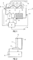
- Fig. 1 shows an internal combustion engine 1 with four cylinders and a arranged on the internal combustion engine 1 exhaust manifold 15.
- a coolant circuit 2 is formed on the internal combustion engine 1.
- the coolant circuit 2 for the internal combustion engine comprises a coolant pump 3, at least one coolant line 4, a cooler 7 and cooling cavities 13 in the internal combustion engine 1.
- the coolant 5 can absorb and remove the heat from the hot internal combustion engine 1.
- the hot coolant is transported from the coolant pump 3 through the coolant line 4 to the cooler 7, where the coolant 5 is usually cooled by passing cold air and then again the internal combustion engine 1 is supplied.
- the coolant 5 of an internal combustion engine 1 in motor vehicles usually consists of water, to which some substances that reduce corrosion are added.
- This water has the property of freezing at temperatures of less than 0 ° C, which can lead to serious damage to the internal combustion engine 1 or the coolant circuit 2. Therefore, the aqueous coolant 5 is usually added substances that lower the freezing point of the solution well below 0 ° C. In the course of a vehicle life, however, it may happen that the concentration of the substances that reduce the freezing point of the coolant 5, too low, whereby a freezing of the internal combustion engine 1 or the coolant circuit 2 is possible. To prevent this, a sensor 8 for monitoring the coolant concentration is permanently and permanently arranged in the coolant circuit 2.
- This sensor 8 for monitoring the coolant concentration may for example be an ultrasonic sensor.
- an expansion vessel 6 can be arranged in the coolant circuit 2. This expansion vessel 6 can compensate for the thermal expansion of the coolant 5 in the coolant circuit 2.
- the sensor 8 for monitoring the coolant concentration may, for. B. may be arranged in or on the coolant cavity 13 of the internal combustion engine 1. In combination or as an independent solution, the sensor 8 for monitoring the coolant concentration may be arranged on or in the coolant pump 3. In addition, the sensor 8 may be arranged to monitor the coolant concentration in or on the coolant line 4 and / or in or on the cooler 7.
- the sensor 8 for monitoring the coolant concentration transmits the detected concentration of the coolant solution 5 to an electronic control unit 9.
- This electronic control unit 9 can determine information about the coolant concentration, the temperature below which the coolant 5 would freeze. This temperature can be compared with an outside temperature, which is transmitted from an ambient temperature sensor 14 to the electronic control unit 9. Once the electronic control unit detects that the outside temperature falls below the glass transition temperature of the coolant 5, the electronic control unit may generate a warning signal and / or electronically ensure that the supercooled and / or frozen internal combustion engine is not started.
- Fig. 2 shows a concentration sensor 8, which is designed as an ultrasonic sensor.
- the sensor element 17 is excited by a frequency generator 10, which is integrated in the electronic control unit 9 to vibrate.
- the sensor element 17 can also be excited to oscillate by an electrical circuit 9, wherein the electrical circuit 9 is a component of the concentration sensor 8 itself.
- These vibrations have frequencies in the ultrasonic range, whereby an ultrasonic wave 11 is emitted and passes through the coolant 5 to a reflector 12. At the reflector 12, the ultrasonic wave 11 is reflected and thrown back to the sensor element 17.
- the sensor element 17 now acts as a receiver for the ultrasonic wave 11, wherein the transit time of the ultrasonic wave 11 from the sensor element 17 via the reflector 12 back to the sensor element 17 is characteristic of the concentration of the freezing point lowering additives in the coolant.
- the sensor 8 shown here for monitoring the coolant concentration can deliver a corresponding signal to the concentration of the coolant to the electronic control unit 9, whereby the electronic control unit 9 can then calculate the temperature from which the coolant 5 would freeze.
- the presented here coolant circuit 2 for an internal combustion engine 1 with at least one sensor 8 for monitoring the coolant concentration can help to avoid expensive damage to the internal combustion engine 1 and thus conserve resources.
Landscapes
- Engineering & Computer Science (AREA)
- Chemical & Material Sciences (AREA)
- Combustion & Propulsion (AREA)
- Mechanical Engineering (AREA)
- General Engineering & Computer Science (AREA)
- Life Sciences & Earth Sciences (AREA)
- Atmospheric Sciences (AREA)
- Investigating Or Analyzing Materials By The Use Of Ultrasonic Waves (AREA)
- Combined Controls Of Internal Combustion Engines (AREA)
Claims (9)
- Circuit de liquide de refroidissement (2) pour un moteur à combustion interne (1), comprenant une pompe à liquide de refroidissement (3), au moins une conduite de liquide de refroidissement (4), un radiateur (7) et une cavité à liquide de refroidissement (13) dans le moteur à combustion interne (1), dans lequel la pompe à liquide de refroidissement (3), la conduite de liquide de refroidissement (4), le radiateur (7) et la cavité à liquide de refroidissement (13) sont remplis d'un liquide de refroidissement (5), dans lequel au moins un capteur (8) servant à surveiller la concentration de liquide de refroidissement est disposé de manière fixe et permanente dans et/ou sur le circuit de liquide de refroidissement (2) et ses résultats de mesure sont transmis à un appareil de commande électronique (9), caractérisé en ce que l'appareil de commande est en outre relié à un capteur de température ambiante (14), l'appareil de commande électronique étant conçu pour déterminer, sur la base des résultats de mesure du capteur (8), une température d'utilisation minimale pour le liquide de refroidissement (5) et pour comparer celle-ci avec le résultat de mesure du capteur de température ambiante (14), et une telle comparaison de la température d'utilisation minimale déterminée pour le liquide de refroidissement (5) avec le résultat de mesure du capteur de température ambiante (14) s'effectuant également après l'arrêt du moteur à combustion interne.
- Circuit de liquide de refroidissement (2) selon la revendication 1, caractérisé en ce que le capteur (8) servant à surveiller la concentration de liquide de refroidissement est un capteur à ultrasons.
- Circuit de liquide de refroidissement (2) selon la revendication 1 ou 2, caractérisé en ce que le circuit de liquide de refroidissement (2) comprend en outre un vase d'expansion (6).
- Circuit de liquide de refroidissement (2) selon la revendication 3, caractérisé en ce que le capteur (8) servant à surveiller la concentration de liquide de refroidissement est disposé dans ou sur le vase d'expansion (6).
- Circuit de liquide de refroidissement (2) selon l'une des revendications précédentes, caractérisé en ce que le capteur (8) servant à surveiller la concentration de liquide de refroidissement est disposé dans ou sur la cavité à liquide de refroidissement (13).
- Circuit de liquide de refroidissement (2) selon l'une des revendications précédentes, caractérisé en ce que le capteur (8) servant à surveiller la concentration de liquide de refroidissement est disposé dans ou sur la pompe à liquide de refroidissement (3).
- Circuit de liquide de refroidissement (2) selon l'une des revendications précédentes, caractérisé en ce que le capteur (8) servant à surveiller la concentration de liquide de refroidissement est disposé dans ou sur la conduite de liquide de refroidissement (4).
- Circuit de liquide de refroidissement (2) selon l'une des revendications précédentes, caractérisé en ce que le capteur (8) servant à surveiller la concentration de liquide de refroidissement est disposé dans ou sur le radiateur (7).
- Circuit de liquide de refroidissement (2) selon l'une des revendications précédentes, caractérisé en ce que l'appareil de commande électronique (9) produit un signal d'avertissement électronique lorsque le résultat de mesure du capteur de température ambiante (14) passe en dessous de la température d'utilisation minimale du liquide de refroidissement (5).
Applications Claiming Priority (2)
| Application Number | Priority Date | Filing Date | Title |
|---|---|---|---|
| DE102012223454.3A DE102012223454A1 (de) | 2012-12-17 | 2012-12-17 | Kühlmittelkreislauf |
| PCT/EP2013/075929 WO2014095451A1 (fr) | 2012-12-17 | 2013-12-09 | Circuit de réfrigérant |
Publications (2)
| Publication Number | Publication Date |
|---|---|
| EP2932064A1 EP2932064A1 (fr) | 2015-10-21 |
| EP2932064B1 true EP2932064B1 (fr) | 2019-09-04 |
Family
ID=49759282
Family Applications (1)
| Application Number | Title | Priority Date | Filing Date |
|---|---|---|---|
| EP13802939.2A Active EP2932064B1 (fr) | 2012-12-17 | 2013-12-09 | Circuit de réfrigérant |
Country Status (5)
| Country | Link |
|---|---|
| US (1) | US9850804B2 (fr) |
| EP (1) | EP2932064B1 (fr) |
| CN (1) | CN104870772A (fr) |
| DE (1) | DE102012223454A1 (fr) |
| WO (1) | WO2014095451A1 (fr) |
Families Citing this family (4)
| Publication number | Priority date | Publication date | Assignee | Title |
|---|---|---|---|---|
| US11129399B2 (en) * | 2016-08-16 | 2021-09-28 | Messer Industries Usa, Inc. | In-line cryogenic method and system for cooling liquid products |
| DE102016124652B3 (de) * | 2016-12-16 | 2018-02-01 | Iav Gmbh Ingenieurgesellschaft Auto Und Verkehr | Verfahren zur Ermittlung einer Kühlmittelkonzentration |
| CN110259568A (zh) * | 2019-06-28 | 2019-09-20 | 潍柴动力股份有限公司 | 一种发动机冷却液检测方法及发动机冷却系统 |
| EP3783275A1 (fr) * | 2019-08-21 | 2021-02-24 | Grundfos Holding A/S | Système de pompe |
Citations (2)
| Publication number | Priority date | Publication date | Assignee | Title |
|---|---|---|---|---|
| JPH10259730A (ja) * | 1997-03-18 | 1998-09-29 | Kubota Corp | エンジンの強制循環式水冷装置 |
| EP2698516A1 (fr) * | 2011-04-13 | 2014-02-19 | Toyota Jidosha Kabushiki Kaisha | Dispositif de diagnostic de véhicule et procédé de diagnostic de véhicule |
Family Cites Families (20)
| Publication number | Priority date | Publication date | Assignee | Title |
|---|---|---|---|---|
| JPS5227938A (en) | 1975-08-28 | 1977-03-02 | Nippon Soken Inc | Antifreezer sensor device |
| JPS6060005B2 (ja) | 1980-07-03 | 1985-12-27 | 日産自動車株式会社 | エンジンの冷却装置 |
| JPS57171019A (en) | 1981-04-11 | 1982-10-21 | Mazda Motor Corp | Controlling device of water pump of engine |
| US4503814A (en) * | 1983-05-12 | 1985-03-12 | Nissan Diesel Motor Company, Limited | System for preventing cavitation in water-cooled internal combustion engine |
| US4905508A (en) * | 1989-03-09 | 1990-03-06 | Thomas A. Ramona | Radiator hose hydrometer |
| GB2360838B (en) * | 2000-03-31 | 2004-04-07 | Rover Group | Cooling system expansion tank |
| JP3851881B2 (ja) * | 2003-02-20 | 2006-11-29 | 本田技研工業株式会社 | 内燃機関の冷却水の温度センサの故障を診断する装置 |
| KR100612964B1 (ko) * | 2004-04-08 | 2006-08-14 | 현대자동차주식회사 | 차량의 서모스탯 모니터링 장치 및 방법 |
| US7367291B2 (en) | 2004-07-23 | 2008-05-06 | General Electric Co. | Locomotive apparatus |
| JP2007023933A (ja) * | 2005-07-19 | 2007-02-01 | Mitsubishi Electric Corp | 内燃機関の制御装置 |
| JP2007247506A (ja) | 2006-03-15 | 2007-09-27 | Toyota Motor Corp | 内燃機関冷却系の不凍液濃度推定装置 |
| US20090311772A1 (en) * | 2008-04-25 | 2009-12-17 | E-Fuel Corporation | Micro refinery for ethanol production |
| JP2010071080A (ja) * | 2008-09-16 | 2010-04-02 | Denso Corp | 車両用冷却システムの異常診断装置 |
| DE112010002904B4 (de) * | 2009-07-13 | 2021-06-17 | Schaeffler Technologies AG & Co. KG | Vorrichtung zum Verhindern des Inbewegungssetzens eines Kraftfahrzeugs |
| EP2441935A4 (fr) * | 2009-09-08 | 2012-09-19 | Toyota Motor Co Ltd | Système de refroidissement pour véhicule |
| JP5201418B2 (ja) * | 2009-11-10 | 2013-06-05 | アイシン精機株式会社 | 内燃機関冷却システム及び内燃機関冷却システムにおける故障判定方法 |
| DE102010027946A1 (de) * | 2010-04-20 | 2011-10-20 | Robert Bosch Gmbh | Überwachungssysten für einen Kühlmittelkreislauf |
| US8346422B2 (en) * | 2010-05-24 | 2013-01-01 | Ford Global Technologies, Llc | Hybrid electric vehicle thermal management system |
| JP2012086735A (ja) * | 2010-10-21 | 2012-05-10 | Toyota Motor Corp | ハイブリッド車両の制御装置 |
| EP2808519B1 (fr) * | 2012-01-25 | 2018-01-03 | Hitachi Construction Machinery Tierra Co., Ltd. | Machine de construction |
-
2012
- 2012-12-17 DE DE102012223454.3A patent/DE102012223454A1/de not_active Ceased
-
2013
- 2013-12-09 US US14/652,671 patent/US9850804B2/en active Active
- 2013-12-09 EP EP13802939.2A patent/EP2932064B1/fr active Active
- 2013-12-09 CN CN201380065760.4A patent/CN104870772A/zh active Pending
- 2013-12-09 WO PCT/EP2013/075929 patent/WO2014095451A1/fr not_active Ceased
Patent Citations (2)
| Publication number | Priority date | Publication date | Assignee | Title |
|---|---|---|---|---|
| JPH10259730A (ja) * | 1997-03-18 | 1998-09-29 | Kubota Corp | エンジンの強制循環式水冷装置 |
| EP2698516A1 (fr) * | 2011-04-13 | 2014-02-19 | Toyota Jidosha Kabushiki Kaisha | Dispositif de diagnostic de véhicule et procédé de diagnostic de véhicule |
Also Published As
| Publication number | Publication date |
|---|---|
| US9850804B2 (en) | 2017-12-26 |
| DE102012223454A1 (de) | 2014-06-18 |
| WO2014095451A1 (fr) | 2014-06-26 |
| CN104870772A (zh) | 2015-08-26 |
| US20150369116A1 (en) | 2015-12-24 |
| EP2932064A1 (fr) | 2015-10-21 |
Similar Documents
| Publication | Publication Date | Title |
|---|---|---|
| DE102013100604B4 (de) | Verbrennungsmotorkühlsystem, elektronisches Thermostatsteuersystem und Steuerverfahren für diese | |
| EP2932064B1 (fr) | Circuit de réfrigérant | |
| DE102008032130B4 (de) | Verfahren und Vorrichtung zur Diagnose einer Kühlmittelpumpe für eine Brennkraftmaschine | |
| DE102016117949B4 (de) | Diagnosevorrichtung | |
| DE102013211308B4 (de) | System, Verfahren und nichtflüchtiges computerlesbares Speichermedium zur Verwendung bei der Berücksichtigung einer Wirkung eines Fernfahrt-Zyklus auf die Restlebensdauer von Motoröl, das in einem Fahrzeug verwendet wird, unter Verwendung eines Fernfahrt-Abschlagwertes | |
| EP3063047B1 (fr) | Procédé pour la détection d'un passage dans une nappe d'eau utilisant des capteurs de distance | |
| DE112016003715T5 (de) | Virtueller reduktionsmittelfüllstandssensor | |
| EP2310645B1 (fr) | Procédé de chauffage sélectif d'une conduite d'agent de réduction | |
| DE102011012441A1 (de) | Verfahren zum Heizen eines Fördersystems | |
| WO2015185568A1 (fr) | Dispositif de fourniture d'un additif liquide | |
| DE102008063968B4 (de) | Dieselmotor, Sollbruchbauteil dafür, sowie Verfahren zum Vermeiden von Beschädigungen eines Dieselmotors | |
| DE202014103956U1 (de) | System zur Reinigung von Abgasen aus einem Verbrennungsmotor | |
| EP1900937A2 (fr) | Procédé de surveillance de fonctions erronées lors du fonctionnement d'automobiles | |
| DE102006016906A1 (de) | Vorrichtung zur Überwachung eines Abgaskatalysators im Abgassystem einer Brennkraftmaschine | |
| DE102017118627A1 (de) | Druckentlastungssystem für dieselabgasfluidspeicher | |
| DE10306412B4 (de) | Abgasanlage einer lambdageregelten Brennkraftmaschine | |
| EP3293380A1 (fr) | Moteur à combustion interne comprenant un circuit de refroidissement et un véhicule terrestre comprenant ce moteur à combustion interne | |
| DE102009036260A1 (de) | Vorratsbehälter | |
| DE102013003144A1 (de) | Verfahren zum Betrieb eines Kühlsystems eines Kraftfahrzeugs und Kraftfahrzeug | |
| DE10123106B4 (de) | Verfahren zum Überwachen eines Kühlflüssigkeitskreislaufs einer Brennkraftmaschine | |
| DE102010004903A1 (de) | Hybridfahrzeug | |
| DE102008002353A1 (de) | Vorrichtung und Verfahren zur Beheizung eines SCR-Pumpenmoduls | |
| DE102005007324B4 (de) | Überwachung von Motorkühlflüssigkeitstemperaturgebern | |
| DE102013211701A1 (de) | Fahrzeugheizsystem sowie Verfahren zum Heizen des Innenraums eines Fahrzeugs mit einem Fahrzeugheizsystem | |
| DE102010010626A1 (de) | Überwachungsvorrichtung für eine Maschine |
Legal Events
| Date | Code | Title | Description |
|---|---|---|---|
| PUAI | Public reference made under article 153(3) epc to a published international application that has entered the european phase |
Free format text: ORIGINAL CODE: 0009012 |
|
| 17P | Request for examination filed |
Effective date: 20150717 |
|
| AK | Designated contracting states |
Kind code of ref document: A1 Designated state(s): AL AT BE BG CH CY CZ DE DK EE ES FI FR GB GR HR HU IE IS IT LI LT LU LV MC MK MT NL NO PL PT RO RS SE SI SK SM TR |
|
| AX | Request for extension of the european patent |
Extension state: BA ME |
|
| DAX | Request for extension of the european patent (deleted) | ||
| GRAP | Despatch of communication of intention to grant a patent |
Free format text: ORIGINAL CODE: EPIDOSNIGR1 |
|
| STAA | Information on the status of an ep patent application or granted ep patent |
Free format text: STATUS: GRANT OF PATENT IS INTENDED |
|
| INTG | Intention to grant announced |
Effective date: 20190322 |
|
| GRAS | Grant fee paid |
Free format text: ORIGINAL CODE: EPIDOSNIGR3 |
|
| GRAA | (expected) grant |
Free format text: ORIGINAL CODE: 0009210 |
|
| STAA | Information on the status of an ep patent application or granted ep patent |
Free format text: STATUS: THE PATENT HAS BEEN GRANTED |
|
| AK | Designated contracting states |
Kind code of ref document: B1 Designated state(s): AL AT BE BG CH CY CZ DE DK EE ES FI FR GB GR HR HU IE IS IT LI LT LU LV MC MK MT NL NO PL PT RO RS SE SI SK SM TR |
|
| REG | Reference to a national code |
Ref country code: GB Ref legal event code: FG4D Free format text: NOT ENGLISH |
|
| REG | Reference to a national code |
Ref country code: CH Ref legal event code: EP |
|
| REG | Reference to a national code |
Ref country code: AT Ref legal event code: REF Ref document number: 1175644 Country of ref document: AT Kind code of ref document: T Effective date: 20190915 |
|
| REG | Reference to a national code |
Ref country code: DE Ref legal event code: R096 Ref document number: 502013013533 Country of ref document: DE |
|
| REG | Reference to a national code |
Ref country code: IE Ref legal event code: FG4D Free format text: LANGUAGE OF EP DOCUMENT: GERMAN |
|
| RAP2 | Party data changed (patent owner data changed or rights of a patent transferred) |
Owner name: CPT GROUP GMBH |
|
| RAP2 | Party data changed (patent owner data changed or rights of a patent transferred) |
Owner name: VITESCO TECHNOLOGIES GMBH |
|
| REG | Reference to a national code |
Ref country code: NL Ref legal event code: MP Effective date: 20190904 |
|
| REG | Reference to a national code |
Ref country code: LT Ref legal event code: MG4D |
|
| PG25 | Lapsed in a contracting state [announced via postgrant information from national office to epo] |
Ref country code: HR Free format text: LAPSE BECAUSE OF FAILURE TO SUBMIT A TRANSLATION OF THE DESCRIPTION OR TO PAY THE FEE WITHIN THE PRESCRIBED TIME-LIMIT Effective date: 20190904 Ref country code: LT Free format text: LAPSE BECAUSE OF FAILURE TO SUBMIT A TRANSLATION OF THE DESCRIPTION OR TO PAY THE FEE WITHIN THE PRESCRIBED TIME-LIMIT Effective date: 20190904 Ref country code: NO Free format text: LAPSE BECAUSE OF FAILURE TO SUBMIT A TRANSLATION OF THE DESCRIPTION OR TO PAY THE FEE WITHIN THE PRESCRIBED TIME-LIMIT Effective date: 20191204 Ref country code: BG Free format text: LAPSE BECAUSE OF FAILURE TO SUBMIT A TRANSLATION OF THE DESCRIPTION OR TO PAY THE FEE WITHIN THE PRESCRIBED TIME-LIMIT Effective date: 20191204 Ref country code: FI Free format text: LAPSE BECAUSE OF FAILURE TO SUBMIT A TRANSLATION OF THE DESCRIPTION OR TO PAY THE FEE WITHIN THE PRESCRIBED TIME-LIMIT Effective date: 20190904 Ref country code: SE Free format text: LAPSE BECAUSE OF FAILURE TO SUBMIT A TRANSLATION OF THE DESCRIPTION OR TO PAY THE FEE WITHIN THE PRESCRIBED TIME-LIMIT Effective date: 20190904 |
|
| REG | Reference to a national code |
Ref country code: DE Ref legal event code: R081 Ref document number: 502013013533 Country of ref document: DE Owner name: VITESCO TECHNOLOGIES GMBH, DE Free format text: FORMER OWNER: CONTINENTAL AUTOMOTIVE GMBH, 30165 HANNOVER, DE |
|
| PG25 | Lapsed in a contracting state [announced via postgrant information from national office to epo] |
Ref country code: RS Free format text: LAPSE BECAUSE OF FAILURE TO SUBMIT A TRANSLATION OF THE DESCRIPTION OR TO PAY THE FEE WITHIN THE PRESCRIBED TIME-LIMIT Effective date: 20190904 Ref country code: LV Free format text: LAPSE BECAUSE OF FAILURE TO SUBMIT A TRANSLATION OF THE DESCRIPTION OR TO PAY THE FEE WITHIN THE PRESCRIBED TIME-LIMIT Effective date: 20190904 Ref country code: GR Free format text: LAPSE BECAUSE OF FAILURE TO SUBMIT A TRANSLATION OF THE DESCRIPTION OR TO PAY THE FEE WITHIN THE PRESCRIBED TIME-LIMIT Effective date: 20191205 Ref country code: ES Free format text: LAPSE BECAUSE OF FAILURE TO SUBMIT A TRANSLATION OF THE DESCRIPTION OR TO PAY THE FEE WITHIN THE PRESCRIBED TIME-LIMIT Effective date: 20190904 Ref country code: AL Free format text: LAPSE BECAUSE OF FAILURE TO SUBMIT A TRANSLATION OF THE DESCRIPTION OR TO PAY THE FEE WITHIN THE PRESCRIBED TIME-LIMIT Effective date: 20190904 |
|
| PG25 | Lapsed in a contracting state [announced via postgrant information from national office to epo] |
Ref country code: NL Free format text: LAPSE BECAUSE OF FAILURE TO SUBMIT A TRANSLATION OF THE DESCRIPTION OR TO PAY THE FEE WITHIN THE PRESCRIBED TIME-LIMIT Effective date: 20190904 Ref country code: EE Free format text: LAPSE BECAUSE OF FAILURE TO SUBMIT A TRANSLATION OF THE DESCRIPTION OR TO PAY THE FEE WITHIN THE PRESCRIBED TIME-LIMIT Effective date: 20190904 Ref country code: RO Free format text: LAPSE BECAUSE OF FAILURE TO SUBMIT A TRANSLATION OF THE DESCRIPTION OR TO PAY THE FEE WITHIN THE PRESCRIBED TIME-LIMIT Effective date: 20190904 Ref country code: PT Free format text: LAPSE BECAUSE OF FAILURE TO SUBMIT A TRANSLATION OF THE DESCRIPTION OR TO PAY THE FEE WITHIN THE PRESCRIBED TIME-LIMIT Effective date: 20200106 Ref country code: PL Free format text: LAPSE BECAUSE OF FAILURE TO SUBMIT A TRANSLATION OF THE DESCRIPTION OR TO PAY THE FEE WITHIN THE PRESCRIBED TIME-LIMIT Effective date: 20190904 |
|
| REG | Reference to a national code |
Ref country code: DE Ref legal event code: R081 Ref document number: 502013013533 Country of ref document: DE Owner name: VITESCO TECHNOLOGIES GMBH, DE Free format text: FORMER OWNER: CPT GROUP GMBH, 30165 HANNOVER, DE |
|
| PG25 | Lapsed in a contracting state [announced via postgrant information from national office to epo] |
Ref country code: SK Free format text: LAPSE BECAUSE OF FAILURE TO SUBMIT A TRANSLATION OF THE DESCRIPTION OR TO PAY THE FEE WITHIN THE PRESCRIBED TIME-LIMIT Effective date: 20190904 Ref country code: CZ Free format text: LAPSE BECAUSE OF FAILURE TO SUBMIT A TRANSLATION OF THE DESCRIPTION OR TO PAY THE FEE WITHIN THE PRESCRIBED TIME-LIMIT Effective date: 20190904 Ref country code: IS Free format text: LAPSE BECAUSE OF FAILURE TO SUBMIT A TRANSLATION OF THE DESCRIPTION OR TO PAY THE FEE WITHIN THE PRESCRIBED TIME-LIMIT Effective date: 20200224 Ref country code: SM Free format text: LAPSE BECAUSE OF FAILURE TO SUBMIT A TRANSLATION OF THE DESCRIPTION OR TO PAY THE FEE WITHIN THE PRESCRIBED TIME-LIMIT Effective date: 20190904 |
|
| REG | Reference to a national code |
Ref country code: DE Ref legal event code: R097 Ref document number: 502013013533 Country of ref document: DE |
|
| PLBE | No opposition filed within time limit |
Free format text: ORIGINAL CODE: 0009261 |
|
| STAA | Information on the status of an ep patent application or granted ep patent |
Free format text: STATUS: NO OPPOSITION FILED WITHIN TIME LIMIT |
|
| PG2D | Information on lapse in contracting state deleted |
Ref country code: IS |
|
| PG25 | Lapsed in a contracting state [announced via postgrant information from national office to epo] |
Ref country code: DK Free format text: LAPSE BECAUSE OF FAILURE TO SUBMIT A TRANSLATION OF THE DESCRIPTION OR TO PAY THE FEE WITHIN THE PRESCRIBED TIME-LIMIT Effective date: 20190904 Ref country code: IS Free format text: LAPSE BECAUSE OF FAILURE TO SUBMIT A TRANSLATION OF THE DESCRIPTION OR TO PAY THE FEE WITHIN THE PRESCRIBED TIME-LIMIT Effective date: 20200105 |
|
| REG | Reference to a national code |
Ref country code: CH Ref legal event code: PL |
|
| 26N | No opposition filed |
Effective date: 20200605 |
|
| REG | Reference to a national code |
Ref country code: BE Ref legal event code: MM Effective date: 20191231 |
|
| PG25 | Lapsed in a contracting state [announced via postgrant information from national office to epo] |
Ref country code: SI Free format text: LAPSE BECAUSE OF FAILURE TO SUBMIT A TRANSLATION OF THE DESCRIPTION OR TO PAY THE FEE WITHIN THE PRESCRIBED TIME-LIMIT Effective date: 20190904 Ref country code: MC Free format text: LAPSE BECAUSE OF FAILURE TO SUBMIT A TRANSLATION OF THE DESCRIPTION OR TO PAY THE FEE WITHIN THE PRESCRIBED TIME-LIMIT Effective date: 20190904 |
|
| GBPC | Gb: european patent ceased through non-payment of renewal fee |
Effective date: 20191209 |
|
| PG25 | Lapsed in a contracting state [announced via postgrant information from national office to epo] |
Ref country code: IE Free format text: LAPSE BECAUSE OF NON-PAYMENT OF DUE FEES Effective date: 20191209 Ref country code: LU Free format text: LAPSE BECAUSE OF NON-PAYMENT OF DUE FEES Effective date: 20191209 Ref country code: GB Free format text: LAPSE BECAUSE OF NON-PAYMENT OF DUE FEES Effective date: 20191209 |
|
| PG25 | Lapsed in a contracting state [announced via postgrant information from national office to epo] |
Ref country code: LI Free format text: LAPSE BECAUSE OF NON-PAYMENT OF DUE FEES Effective date: 20191231 Ref country code: CH Free format text: LAPSE BECAUSE OF NON-PAYMENT OF DUE FEES Effective date: 20191231 Ref country code: BE Free format text: LAPSE BECAUSE OF NON-PAYMENT OF DUE FEES Effective date: 20191231 |
|
| REG | Reference to a national code |
Ref country code: AT Ref legal event code: MM01 Ref document number: 1175644 Country of ref document: AT Kind code of ref document: T Effective date: 20191209 |
|
| PG25 | Lapsed in a contracting state [announced via postgrant information from national office to epo] |
Ref country code: AT Free format text: LAPSE BECAUSE OF NON-PAYMENT OF DUE FEES Effective date: 20191209 Ref country code: CY Free format text: LAPSE BECAUSE OF FAILURE TO SUBMIT A TRANSLATION OF THE DESCRIPTION OR TO PAY THE FEE WITHIN THE PRESCRIBED TIME-LIMIT Effective date: 20190904 |
|
| PG25 | Lapsed in a contracting state [announced via postgrant information from national office to epo] |
Ref country code: MT Free format text: LAPSE BECAUSE OF FAILURE TO SUBMIT A TRANSLATION OF THE DESCRIPTION OR TO PAY THE FEE WITHIN THE PRESCRIBED TIME-LIMIT Effective date: 20190904 Ref country code: HU Free format text: LAPSE BECAUSE OF FAILURE TO SUBMIT A TRANSLATION OF THE DESCRIPTION OR TO PAY THE FEE WITHIN THE PRESCRIBED TIME-LIMIT; INVALID AB INITIO Effective date: 20131209 |
|
| REG | Reference to a national code |
Ref country code: DE Ref legal event code: R081 Ref document number: 502013013533 Country of ref document: DE Owner name: SCHAEFFLER TECHNOLOGIES AG & CO. KG, DE Free format text: FORMER OWNER: VITESCO TECHNOLOGIES GMBH, 30165 HANNOVER, DE Ref country code: DE Ref legal event code: R081 Ref document number: 502013013533 Country of ref document: DE Owner name: VITESCO TECHNOLOGIES GMBH, DE Free format text: FORMER OWNER: VITESCO TECHNOLOGIES GMBH, 30165 HANNOVER, DE |
|
| REG | Reference to a national code |
Ref country code: DE Ref legal event code: R084 Ref document number: 502013013533 Country of ref document: DE |
|
| PG25 | Lapsed in a contracting state [announced via postgrant information from national office to epo] |
Ref country code: TR Free format text: LAPSE BECAUSE OF FAILURE TO SUBMIT A TRANSLATION OF THE DESCRIPTION OR TO PAY THE FEE WITHIN THE PRESCRIBED TIME-LIMIT Effective date: 20190904 |
|
| PG25 | Lapsed in a contracting state [announced via postgrant information from national office to epo] |
Ref country code: MK Free format text: LAPSE BECAUSE OF FAILURE TO SUBMIT A TRANSLATION OF THE DESCRIPTION OR TO PAY THE FEE WITHIN THE PRESCRIBED TIME-LIMIT Effective date: 20190904 |
|
| P01 | Opt-out of the competence of the unified patent court (upc) registered |
Effective date: 20230530 |
|
| PGFP | Annual fee paid to national office [announced via postgrant information from national office to epo] |
Ref country code: DE Payment date: 20241231 Year of fee payment: 12 |
|
| PGFP | Annual fee paid to national office [announced via postgrant information from national office to epo] |
Ref country code: FR Payment date: 20241224 Year of fee payment: 12 |
|
| REG | Reference to a national code |
Ref country code: DE Ref legal event code: R081 Ref document number: 502013013533 Country of ref document: DE Owner name: SCHAEFFLER TECHNOLOGIES AG & CO. KG, DE Free format text: FORMER OWNER: VITESCO TECHNOLOGIES GMBH, 93055 REGENSBURG, DE |
|
| PGFP | Annual fee paid to national office [announced via postgrant information from national office to epo] |
Ref country code: IT Payment date: 20241227 Year of fee payment: 12 |