EP2932194B1 - Ins multi-imu destiné à la commande d'un véhicule - Google Patents
Ins multi-imu destiné à la commande d'un véhicule Download PDFInfo
- Publication number
- EP2932194B1 EP2932194B1 EP13815257.4A EP13815257A EP2932194B1 EP 2932194 B1 EP2932194 B1 EP 2932194B1 EP 13815257 A EP13815257 A EP 13815257A EP 2932194 B1 EP2932194 B1 EP 2932194B1
- Authority
- EP
- European Patent Office
- Prior art keywords
- rigid body
- imu
- joint
- velocity
- gnss
- Prior art date
- Legal status (The legal status is an assumption and is not a legal conclusion. Google has not performed a legal analysis and makes no representation as to the accuracy of the status listed.)
- Active
Links
Images


Classifications
-
- G—PHYSICS
- G01—MEASURING; TESTING
- G01S—RADIO DIRECTION-FINDING; RADIO NAVIGATION; DETERMINING DISTANCE OR VELOCITY BY USE OF RADIO WAVES; LOCATING OR PRESENCE-DETECTING BY USE OF THE REFLECTION OR RERADIATION OF RADIO WAVES; ANALOGOUS ARRANGEMENTS USING OTHER WAVES
- G01S19/00—Satellite radio beacon positioning systems; Determining position, velocity or attitude using signals transmitted by such systems
- G01S19/01—Satellite radio beacon positioning systems transmitting time-stamped messages, e.g. GPS [Global Positioning System], GLONASS [Global Orbiting Navigation Satellite System] or GALILEO
- G01S19/13—Receivers
- G01S19/14—Receivers specially adapted for specific applications
-
- E—FIXED CONSTRUCTIONS
- E02—HYDRAULIC ENGINEERING; FOUNDATIONS; SOIL SHIFTING
- E02F—DREDGING; SOIL-SHIFTING
- E02F9/00—Component parts of dredgers or soil-shifting machines, not restricted to one of the kinds covered by groups E02F3/00 - E02F7/00
- E02F9/26—Indicating devices
- E02F9/264—Sensors and their calibration for indicating the position of the work tool
-
- A—HUMAN NECESSITIES
- A01—AGRICULTURE; FORESTRY; ANIMAL HUSBANDRY; HUNTING; TRAPPING; FISHING
- A01B—SOIL WORKING IN AGRICULTURE OR FORESTRY; PARTS, DETAILS, OR ACCESSORIES OF AGRICULTURAL MACHINES OR IMPLEMENTS, IN GENERAL
- A01B79/00—Methods for working soil
- A01B79/005—Precision agriculture
-
- G—PHYSICS
- G01—MEASURING; TESTING
- G01C—MEASURING DISTANCES, LEVELS OR BEARINGS; SURVEYING; NAVIGATION; GYROSCOPIC INSTRUMENTS; PHOTOGRAMMETRY OR VIDEOGRAMMETRY
- G01C21/00—Navigation; Navigational instruments not provided for in groups G01C1/00 - G01C19/00
- G01C21/10—Navigation; Navigational instruments not provided for in groups G01C1/00 - G01C19/00 by using measurements of speed or acceleration
- G01C21/12—Navigation; Navigational instruments not provided for in groups G01C1/00 - G01C19/00 by using measurements of speed or acceleration executed aboard the object being navigated; Dead reckoning
- G01C21/16—Navigation; Navigational instruments not provided for in groups G01C1/00 - G01C19/00 by using measurements of speed or acceleration executed aboard the object being navigated; Dead reckoning by integrating acceleration or speed, i.e. inertial navigation
- G01C21/165—Navigation; Navigational instruments not provided for in groups G01C1/00 - G01C19/00 by using measurements of speed or acceleration executed aboard the object being navigated; Dead reckoning by integrating acceleration or speed, i.e. inertial navigation combined with non-inertial navigation instruments
-
- G—PHYSICS
- G05—CONTROLLING; REGULATING
- G05D—SYSTEMS FOR CONTROLLING OR REGULATING NON-ELECTRIC VARIABLES
- G05D1/00—Control of position, course, altitude or attitude of land, water, air or space vehicles, e.g. using automatic pilots
- G05D1/02—Control of position or course in two dimensions
- G05D1/021—Control of position or course in two dimensions specially adapted to land vehicles
- G05D1/0268—Control of position or course in two dimensions specially adapted to land vehicles using internal positioning means
- G05D1/027—Control of position or course in two dimensions specially adapted to land vehicles using internal positioning means comprising intertial navigation means, e.g. azimuth detector
-
- G—PHYSICS
- G05—CONTROLLING; REGULATING
- G05D—SYSTEMS FOR CONTROLLING OR REGULATING NON-ELECTRIC VARIABLES
- G05D1/00—Control of position, course, altitude or attitude of land, water, air or space vehicles, e.g. using automatic pilots
- G05D1/02—Control of position or course in two dimensions
- G05D1/021—Control of position or course in two dimensions specially adapted to land vehicles
- G05D1/0276—Control of position or course in two dimensions specially adapted to land vehicles using signals provided by a source external to the vehicle
- G05D1/0278—Control of position or course in two dimensions specially adapted to land vehicles using signals provided by a source external to the vehicle using satellite positioning signals, e.g. GPS
-
- A—HUMAN NECESSITIES
- A01—AGRICULTURE; FORESTRY; ANIMAL HUSBANDRY; HUNTING; TRAPPING; FISHING
- A01B—SOIL WORKING IN AGRICULTURE OR FORESTRY; PARTS, DETAILS, OR ACCESSORIES OF AGRICULTURAL MACHINES OR IMPLEMENTS, IN GENERAL
- A01B69/00—Steering of agricultural machines or implements; Guiding agricultural machines or implements on a desired track
- A01B69/007—Steering or guiding of agricultural vehicles, e.g. steering of the tractor to keep the plough in the furrow
- A01B69/008—Steering or guiding of agricultural vehicles, e.g. steering of the tractor to keep the plough in the furrow automatic
Definitions
- the disclosure is related to precision agricultural vehicle and heavy equipment control.
- GNSS global navigational satellite system
- GNSS-derived position to guide a vehicle control point.
- the control point is rarely coincident with the location of the vehicle's GNSS antenna.
- the antenna is often mounted relatively high, on top of an operator cab for instance, to give it a clear view of GNSS satellites.
- the control point is typically a location that simplifies guidance system design.
- An example control point is the center of a tractor axle.
- a GNSS antenna and a vehicle control point are connected by a rigid body.
- their relative position and relative orientation are constant; equivalently, there is a "rigid body relationship" between the two.
- the position and velocity of the control point can be estimated by using an inertial measurement unit (IMU) to estimate the attitude of the rigid body.
- IMU inertial measurement unit
- An inertial navigation system (INS) then combines GNSS position and velocity estimates for the antenna with IMU attitude estimates for the rigid body to estimate position, velocity and attitude at the control point.
- GNSS antennas are not always connected to vehicle control points by such simple relationships. What are needed are systems to locate and orient a vehicle control point using GNSS-derived position and velocity when the spatial relationship between the GNSS antenna and the control point is not constant.
- US 2012/174445 discloses a global navigation satellite sensor system (GNSS) and gyroscope control system for vehicle steering control comprising a GNSS receiver and antennas at a fixed spacing to determine a vehicle position, velocity and at least one of a heading angle, a pitch angle and a roll angle based on carrier phase position differences.
- the roll angle facilitates correction of the lateral motion induced position errors resultant from motion of the antennae as the vehicle moves based on an offset to ground and the roll angle.
- Alternative aspects include multiple-antenna GNSS guidance methods for high-dynamic roll compensation, real-time kinematic (RTK) using single-frequency (L1) receivers, fixed and moving baselines between antennas, multi-position GNSS tail guidance ("breadcrumb following") for crosstrack error correction, guiding multiple vehicles and pieces of equipment relative to each other, and snow grooming equipment and method applications.
- RTK real-time kinematic
- L1 single-frequency
- the present invention addresses the above-mentioned problems and/or disadvantages by providing a method according to claim 1 and a system according to claim 8.
- Multi-IMU INS for vehicle control allows GNSS-derived position and velocity to be measured at an antenna and applied to the estimation of position, velocity and attitude at a separate control point even when the spatial relationship between antenna and control point is not constant. This new capability reduces errors associated with assuming a rigid body relationship.
- multi-IMU INS extends vehicle guidance concepts to vehicle component control. Rather than merely estimating position, velocity and attitude at one control point, multi-IMU INS can provide such information for sub-assemblies such as spray booms, grain chutes, excavator buckets, etc.
- Multi-IMU INS is described below with the aid of four examples.
- a vehicle is modeled as being composed of rigid bodies connected by joints.
- the combination of a GNSS receiver and an IMU on one rigid body of a vehicle is used to create a virtual GNSS receiver at a joint connecting to a second rigid body.
- Attitude and acceleration estimates from an IMU on the second rigid body are then combined with position and velocity estimates from the virtual GNSS receiver to estimate position, velocity and attitude anywhere within the second rigid body.
- the cab of the state-of-the-art Fendt 900 Vario farm tractor is described by its manufacturer as an "executive corner office with lots of space.” Indeed, with full climate control, a mini-fridge for beverages, multiple electronic displays and guest seating included, the analogy is not far off.
- the cab also features a three point suspension to reduce vibrations and provide maximum ride comfort. The entire cab moves with respect to the tractor's chassis. The suspension reduces operator fatigue and increases productivity; unfortunately, it also degrades the performance of conventional tractor autopilot systems.
- multi-IMU INS uses two IMUs to account for the relative motion of tractor cab and chassis thus supplying an autopilot with accurate control point position, velocity and attitude.
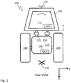
- Fig. 1 is a rear view of a farm tractor 100 with a suspended cab 105.
- a GNSS antenna 110 is mounted on the cab.
- IMU 115 estimates the cab's acceleration and rotation rate.
- the cab is attached to tractor chassis 125 by shock absorbers 120, 122.
- IMU 130 estimates the chassis's acceleration and rotation rate.
- An "X" marks the tractor control point on the ground directly under the center of the tractor's rear axle.
- Tires 140 are assumed to be rigid enough so that there is a rigid-body relationship between IMU 130 and the control point.
- y and z axes are shown to help orient Fig. 1 in a right-hand x, y, z coordinate system also illustrated in Fig. 2 .
- Fig. 2 is a side view of the farm tractor of Fig. 1 .
- heavy dashed lines help to show the outlines of cab 105 and chassis 125.
- Shock absorber 122 is illustrated in different proportion in Figs. 1 and 2 , but the conceptual relationship between the shock absorbers and cab 105 and chassis 125 is the same in each case.
- hinge 145 Also illustrated in Fig. 2 is hinge 145. Hinge 145 allows the cab and chassis to pitch about the y-axis with respect to one another, but not to yaw about the z-axis.
- hinge 145 is an example of a revolute joint connecting rigid body components of an agricultural vehicle or heavy machine. The overall motion between cab and chassis is constrained by it.
- Revolute joints are simpler than spherical ball joints and therefore the relative motion between rigid bodies connected by them may be simpler than the relative motion between rigid bodies connected by spherical ball joints.
- Recognition of constraints, such as a no-yaw constraint between tractor cab and chassis, may lead to simplifications in multi-IMU INS design. In the examples that follow, however, no specific simplified joint is assumed.
- Figs. 3A and 3B are stick models for side and front views of a vehicle.
- GNSS antenna 305 is mounted on rigid body 310 which is connected to rigid body 330 by joint 320.
- Joint 320 may be a spherical ball joint, or a simpler, constrained joint.
- IMU 315 estimates the attitude and rotation rate of rigid body 310 while IMU 325 estimates the attitude and rotation rate of rigid body 330.
- Control point 335 is located on or within rigid body 330 or else has a rigid body relationship to it.
- Fig. 3A provides a side view
- Fig. 3B provides a front view as indicated by the x, y, z axes.
- rigid body 310 is a model for tractor cab 105 and rigid body 330 is a model for tractor chassis 125.
- stick models of Figs. 3 are also applicable to a wide range of similar situations involving agricultural vehicles or heavy equipment.
- GNSS antenna 305 were mounted on rigid body 330, e.g. at joint 320, then the problem of estimating position, velocity and attitude at control point 335 would be the conventional one. It would be solved by combining GNSS information with attitude information from IMU 325 in an INS.
- GNSS 305 is separated from rigid body 330 by rigid body 310 and joint 320.
- Figs. 4 illustrate a strategy for creating a "virtual GNSS" mounted on rigid body 330 and thereby reducing the problem to the conventional one.
- Fig. 4A is a stick model of a vehicle.
- GNSS antenna 405 is mounted on rigid body 410 which is connected to rigid body 430 by joint 420.
- Joint 420 may be a spherical ball joint, for example.
- IMU 415 estimates the attitude and rotation rate of rigid body 410 while IMU 425 estimates the attitude and rotation rate of rigid body 430.
- Control point 435 is located on or within rigid body 430 or else has a rigid body relationship to it. Said another way, the spatial relationship between the two is fixed.
- Fig. 4B is a block diagram of a multi-IMU INS corresponding to the stick model of Fig. 4A .
- the outputs of GNSS receiver 455 and IMU 1 465 are combined in INS 1 470.
- the GNSS receiver, IMU 1 and INS 1 may be thought of as a virtual GNSS receiver 475 that provides position, velocity and attitude at joint 420.
- the outputs of virtual GNSS receiver 475 and IMU 2 480 are combined in INS 2 485 using conventional digital filtering techniques including, for example, Kalman filtering.
- INS 2 provides position, velocity and attitude at control point 435.
- GNSS receiver 455 obtains signals from GNSS antenna 405 and IMU 1 465 corresponds to IMU 415.
- IMU 2 480 corresponds to IMU 425.
- the system of Fig. 4B is an example of a loosely coupled approach to INS meaning that INS 1 and INS 2 use GNSS code-based position and velocity fixes, rather than GNSS pseudoranges and Doppler corrections, in digital filters (e.g. Kalman filters) that estimate state vectors having roughly a dozen or so components.
- Tightly coupled INS is an alternative; however, state vectors in tightly coupled INS have upward of 50 or 60 components (e.g. satellite pseudoranges) which greatly increases system complexity.
- Deeply coupled INS in which IMU output is used to aid GNSS tracking loops, is a third approach. Loosely coupled INS is adequate for the case of the suspended tractor cab, especially when practical relative motion constraints are considered.
- Fig. 4B may be applied to other vehicle control applications in agriculture and civil engineering. Examples involving spray boom control, a harvester unloading chute, and an excavator are given below.
- multiple IMUs are used to define spatial relationships between parts of a machine that may each be modeled as rigid bodies. Multiple IMUs thereby allow GNSS-derived position and velocity estimates to be applied to components of a vehicle or machine that are not part of the same rigid body to which the GNSS antenna is mounted.
- Figs. 5A, 5B and 5C show a spray vehicle with a pivoting spray boom.
- Fig. 5A illustrates spray vehicle 505 that carries spray boom 510 over a farm field.
- Sensors such as 515, are used to detect the height of the boom over the field.
- Sensor 515 may be an ultrasonic ranging device, for example.
- Fig. 5B provides a closer look at the spray vehicle and spray boom of Fig. 5A .
- GNSS antenna 520, spray vehicle IMU 1 525, boom IMU 2 530 and boom pivot bearing 540 are visible.
- the boom pivot bearing may also be moved up and down by actuators mounted to the spray vehicle.
- a spray boom control system tries to maintain constant boom height over a farm field. This task is complicated, however, by variable terrain.
- Fig. 5C shows an exaggerated example of the spray vehicle going over a bump. Ideally the spray boom does not change height or tilt when the spray vehicle goes over the bump. Put another way, a spray boom control system can operate more precisely if the motion of the spray boom can be decoupled from the motion of the tractor.
- a virtual GNSS receiver at the joint between rigid bodies; in this case, the pivot bearing that connects the spray vehicle and the spray boom.
- the spray vehicle is modeled by rigid body 410 and the spray boom is modeled by rigid body 430.
- a virtual GNSS receiver is created at pivot bearing 540 by the combination of GNSS antenna 520 and IMU 1525.
- the output of this virtual GNSS receiver is then combined with the output of IMU 2 530 in an INS.
- a boom control system can then take advantage of GNSS position and velocity estimates for its control point which may be a point on the boom, for example.
- the multi-IMU INS approach decouples the dynamics of a spray boom from those of the spray vehicle that carries it, thus simplifying the design, and improving the performance, of a spray boom control system.
- a combine harvester unloads grain through a chute into a cart driving alongside.
- Today this procedure relies on the skill and experience of the combine operator and the grain cart driver to keep the cart and combine in proper relative position while moving in a farm field. If the position and velocity of the grain chute's nozzle are known accurately, however, a grain cart autopilot can drive the cart to position it with respect to the chute.
- Figs. 6A and 6B show a combine harvester and grain cart in head-on and top view, respectively.
- combine harvester 605 unloads grain into cart 630.
- GNSS antenna 610 and IMU 2 615 are mounted on the combine harvester.
- IMU 1 625 is mounted on grain chute 620.
- the chute is connected to the harvester by a joint that permits motion characterized by polar angle ⁇ and azimuth angle ⁇ as shown in the figures.
- Figs. 6 The situation of Figs. 6 is directly analogous to the model of Fig. 4A .
- the combine harvester corresponds to rigid body 410 while the grain chute corresponds to rigid body 430.
- the nozzle from which grain is expelled from the chute corresponds to control point 435.
- GNSS position and velocity from antenna 610 may be combined with attitude and acceleration from IMU 2 615 in an INS to create a virtual GNSS receiver at the joint connecting the harvester and its grain chute. Position and velocity from this virtual GNSS may then be combined with attitude and acceleration from IMU 1 625 to obtain position, velocity and attitude at a control point having a rigid body relationship with the chute; e.g. the grain nozzle at the end of the chute.
- a fourth example of multi-IMU INS is excavator control.
- the chassis, boom, stick and bucket of an excavator form a chain of rigid bodies connected by joints.
- the excavator therefore fits the framework for carrying GNSS position and velocity from one rigid body to another that is described above.
- Fig. 7 shows excavator 705.
- excavator chassis 710 is connected to boom 715 by joint 765.
- the boom is connected to stick 720 by joint 770.
- Stick 720 is connected to bucket 725 by joint 775.
- Teeth 730 are fixed on the bucket.
- GNSS antenna 735 and IMU 1 740 are mounted on the chassis.
- IMU 2 745 is mounted on the boom.
- GNSS antenna 750 and IMU 3 755 are mounted on the stick.
- IMU 4 760 is mounted on the bucket.
- the control point of the excavator is its teeth 730.
- GNSS derived position and velocity, and attitude of the teeth may be used as inputs to an excavator control system that digs precise holes automatically, for instance.
- One approach to obtaining GNSS position and velocity at the teeth is to use GNSS 750 and IMU 3 to create a virtual GNSS at joint 775. That virtual GNSS may then be combined with IMU 4 760. This approach corresponds exactly to the model of Figs. 4 .
- GNSS 735 and IMU 1 740 may be used to create a virtual GNSS at joint 765. That virtual GNSS may then be combined with IMU 2 745 to create a virtual GNSS at joint 770. From there, the same procedure may be repeated with IMU 3 755 and IMU 4 760 to estimate the position and velocity of the teeth.
- multi-IMU INS for vehicle control allows GNSS-derived position and velocity to be measured at an antenna and applied to the estimation of position, velocity and attitude at a separate control point even when the spatial relationship between antenna and control point is not constant.
- Principles of multi-IMU INS have been described in terms of four examples.
- rigid bodies are connected by joints.
- GNSS derived position and velocity obtained at one rigid body may be used at another rigid body when the spatial relationship between rigid bodies is estimated by IMUs mounted on each one.
- Position, velocity and attitude estimates may be used by systems that provide automatic control not only for a vehicle as a whole, but also for rigid body components of the vehicle such as cabs, booms, chutes, sticks and buckets.
- Multi-IMU INS for vehicle control allowing GNSS-derived position and velocity to be measured at an antenna and applied to the estimation of position, velocity and attitude at a separate control point even when the spatial relationship between antenna and control point is not constant.
Landscapes
- Engineering & Computer Science (AREA)
- Radar, Positioning & Navigation (AREA)
- Remote Sensing (AREA)
- Physics & Mathematics (AREA)
- General Physics & Mathematics (AREA)
- Automation & Control Theory (AREA)
- Aviation & Aerospace Engineering (AREA)
- Life Sciences & Earth Sciences (AREA)
- General Engineering & Computer Science (AREA)
- Structural Engineering (AREA)
- Civil Engineering (AREA)
- Mechanical Engineering (AREA)
- Soil Sciences (AREA)
- Environmental Sciences (AREA)
- Mining & Mineral Resources (AREA)
- Computer Networks & Wireless Communication (AREA)
- Control Of Position, Course, Altitude, Or Attitude Of Moving Bodies (AREA)
- Guiding Agricultural Machines (AREA)
- Position Fixing By Use Of Radio Waves (AREA)
Claims (14)
- Procédé comprenant les étapes consistant à :monter un récepteur GNSS (110 ; 405 ; 455 ; 520 ; 610 ; 735 ; 750) et une première IMU (115 ; 415 ; 465 ; 525 ; 615 ; 740 ; 755) sur un premier corps rigide (105 ; 410 ; 505 ; 605 ; 710 ; 720) ;monter une seconde IMU (130 ; 425 ; 480 ; 530 ; 625 ; 745 ; 760) sur un second corps rigide (125 ; 430 ; 510 ; 620 ; 715 ; 725), le second corps rigide (125 ; 430 ; 510 ; 620 ; 715 ; 725) étant relié au premier corps rigide (105 ; 410 ; 505 ; 605 ; 710 ; 720) par un raccord (145 ; 420 ; 540 ; 765 ; 775) ;combiner les estimations de position et de vitesse provenant du récepteur GNSS (110 ; 405 ; 455 ; 520 ; 610 ; 735 ; 750) avec les estimations de variation d'assiette et d'accélération provenant de la première IMU (115 ; 415 ; 465 ; 615 ; 740 ; 755) dans un premier INS (470) pour estimer la position et la vitesse d'un récepteur GNSS (475) virtuel situé au niveau du raccord (145 ; 420 ; 540 ; 765 ; 775) ; et,combiner les estimations de position et de vitesse dudit récepteur GNSS (475) virtuel au niveau du raccord (145 ; 420 ; 540 ; 765 ; 775) avec les estimations de variation d'assiette et d'accélération de la seconde IMU (130 ; 425 ; 480 ; 530 ; 625 ; 745 ; 760) dans un second INS (485) pour estimer la position, la vitesse et l'assiette au niveau d'un point de contrôle (135 ; 435 ; 515 ; 770 ; 730) ayant une relation spatiale fixe avec le second corps rigide (125 ; 430 ; 510 ; 605 ; 715 ; 725).
- Procédé selon la revendication 1, le raccord (420 ; 540 ; 765) étant une charnière.
- Procédé selon la revendication 1, le raccord étant un joint à rotule sphérique (420).
- Procédé selon la revendication 1 ou 2, le premier corps rigide étant une cabine de tracteur (105) et le second corps rigide étant un châssis de tracteur (125).
- Procédé selon la revendication 1, le premier corps rigide étant un véhicule de pulvérisation agricole (505) et le second corps rigide étant une rampe de pulvérisation (510).
- Procédé selon la revendication 1, le premier corps rigide (605) étant une moissonneuse-batteuse et le second corps rigide (620) étant une goulotte de déchargement du grain.
- Procédé selon la revendication 1, le premier corps rigide étant un bras excavateur (720) et le second corps rigide étant un godet excavateur (725).
- Système, comprenant :un récepteur GNSS (110 ; 405 ; 455 ; 520 ; 610 ; 735 ; 750) et une première IMU (115 ; 415 ; 465 ; 525 ; 615 ; 740 ; 755) montés sur un premier corps rigide (105 ; 410 ; 505 ; 605 ; 710 ; 720) ;une seconde IMU (130 ; 425 ; 480 ; 530 ; 625 ; 745 ; 760) montée sur un second corps rigide (125 ; 430 ; 510 ; 620 ; 715 ; 725), le second corps rigide (125 ; 430 ; 510 ; 620 ; 715 ; 725) étant relié au premier corps rigide (105 ; 410 ; 505 ; 605 ; 710 ; 720) par un raccord (145 ; 420 ; 540 ; 765 ; 775) ;un premier INS qui estime la position et la vitesse d'un récepteur GNS virtuel (475) situé au niveau du raccord (145 ; 420 ; 540 ; 765 ; 775) en combinant les estimations de position et de vitesse du récepteur GNSS (110 ; 405 ; 455 ; 520 ; 610 ; 735 ; 750) avec les estimations de variation d'assiette et d'accélération de la première IMU (115 ; 415 ; 465 ; 525 ; 615 ; 740 ; 755) ; et,un second INS qui estime la position, la vitesse et l'assiette au niveau d'un point de contrôle (135 ; 435 ; 515 ; 770 ; 730) ayant une relation spatiale fixe avec le second corps rigide (125 ; 430 ; 510 ; 620 ; 715 ; 725) en combinant les estimations de position et de vitesse dudit récepteur GNSS virtuel (475) au niveau du raccord (145 ; 420 ; 540 ; 765 ; 775) avec les estimations de variation d'assiette et d'accélération de la seconde IMU (130 ; 425 ; 480 ; 530 ; 625 ; 745 ; 760).
- Système selon la revendication 8, le raccord (420 ; 540 ; 765) étant une charnière.
- Système selon la revendication 8, le raccord (420) étant un joint à rotule sphérique.
- Système selon la revendication 8 ou 9, le premier corps rigide étant une cabine de tracteur (105) et le second corps rigide étant un châssis de tracteur (125).
- Système selon la revendication 8, le premier corps rigide étant un véhicule de pulvérisation agricole (505) et le second corps rigide étant une rampe de pulvérisation (510).
- Système selon la revendication 8, le premier corps rigide étant une moissonneuse-batteuse (605) et le second corps rigide étant une goulotte de déchargement du grain (620).
- Système selon la revendication 8, le premier corps rigide étant un bras excavateur (720) et le second corps rigide étant un godet excavateur (725).
Applications Claiming Priority (2)
| Application Number | Priority Date | Filing Date | Title |
|---|---|---|---|
| US13/716,486 US20140168009A1 (en) | 2012-12-17 | 2012-12-17 | Multi-IMU INS for vehicle control |
| PCT/US2013/073421 WO2014099403A1 (fr) | 2012-12-17 | 2013-12-05 | Ins multi-imu destiné à la commande d'un véhicule |
Publications (2)
| Publication Number | Publication Date |
|---|---|
| EP2932194A1 EP2932194A1 (fr) | 2015-10-21 |
| EP2932194B1 true EP2932194B1 (fr) | 2019-03-06 |
Family
ID=49887265
Family Applications (1)
| Application Number | Title | Priority Date | Filing Date |
|---|---|---|---|
| EP13815257.4A Active EP2932194B1 (fr) | 2012-12-17 | 2013-12-05 | Ins multi-imu destiné à la commande d'un véhicule |
Country Status (3)
| Country | Link |
|---|---|
| US (1) | US20140168009A1 (fr) |
| EP (1) | EP2932194B1 (fr) |
| WO (1) | WO2014099403A1 (fr) |
Cited By (1)
| Publication number | Priority date | Publication date | Assignee | Title |
|---|---|---|---|---|
| US12486644B2 (en) | 2022-08-04 | 2025-12-02 | Caterpillar Trimble Control Technologies Llc | Yaw estimation systems and methods for rigid bodies of earthmoving machines connected by a revolute joint |
Families Citing this family (31)
| Publication number | Priority date | Publication date | Assignee | Title |
|---|---|---|---|---|
| US9781915B2 (en) * | 2013-03-14 | 2017-10-10 | Agjunction Llc | Implement and boom height control system and method |
| US9945957B2 (en) | 2013-03-14 | 2018-04-17 | Agjunction Llc | Machine control system and method |
| US20160286713A1 (en) * | 2013-11-04 | 2016-10-06 | Pastoral Robotics Limited | Apparatus and methods for excreta detection and treatment |
| KR102550595B1 (ko) | 2014-12-08 | 2023-06-30 | 로힛 세스 | 착용가능 무선 hmi 디바이스 |
| US20180024252A1 (en) * | 2015-03-02 | 2018-01-25 | Agco International Gmbh | Guidance system with navigation point correction |
| JP6437640B2 (ja) * | 2015-05-07 | 2018-12-12 | ヤンマー株式会社 | 自律走行車の誘導制御システム |
| US10066370B2 (en) * | 2015-10-19 | 2018-09-04 | Caterpillar Inc. | Sensor fusion for implement position estimation and control |
| US9638525B1 (en) * | 2016-01-04 | 2017-05-02 | Caterpillar Inc. | Systems and methods for monitoring positioning of a machine by utilizing a virtual IMU |
| JP6880677B2 (ja) * | 2016-11-29 | 2021-06-02 | 株式会社タダノ | 作業車両 |
| US10407879B2 (en) | 2017-02-08 | 2019-09-10 | Deere & Company | System and method for remote work implement angular position display |
| JP6892363B2 (ja) * | 2017-10-06 | 2021-06-23 | ヤンマーパワーテクノロジー株式会社 | トラクタ |
| KR102745013B1 (ko) * | 2017-12-18 | 2024-12-20 | 가부시끼 가이샤 구보다 | 작업차 및 트랙터 |
| JP6858694B2 (ja) * | 2017-12-18 | 2021-04-14 | 株式会社クボタ | トラクタ |
| CN109099910A (zh) * | 2018-06-29 | 2018-12-28 | 广东星舆科技有限公司 | 基于惯性导航单元阵列的高精度惯性导航系统及实现方法 |
| DE102018118147A1 (de) * | 2018-07-26 | 2020-01-30 | Liebherr-Mining Equipment Colmar Sas | Verfahren zum Bestimmen eines Winkels eines Arbeitsgeräts einer Maschine |
| US10753752B2 (en) | 2018-07-26 | 2020-08-25 | Trimble Inc. | Vehicle manual guidance systems with steering wheel angle sensors and road wheel angle sensors |
| JP7182408B2 (ja) * | 2018-09-20 | 2022-12-02 | 株式会社クボタ | 田植機 |
| JP7074657B2 (ja) * | 2018-12-20 | 2022-05-24 | 株式会社クボタ | 作業車 |
| CN114556050A (zh) * | 2019-06-17 | 2022-05-27 | 罗希特·塞思 | 使用具有漂移校正的运动传感器的相对位置跟踪 |
| EP4028844B1 (fr) | 2019-09-09 | 2024-11-27 | Mtd Products Inc. | Dispositif d'équipement électrique cinématique en temps réel à direction automatique |
| JP7144397B2 (ja) * | 2019-12-26 | 2022-09-29 | ヤンマーパワーテクノロジー株式会社 | トラクタ |
| US11649613B2 (en) * | 2020-02-25 | 2023-05-16 | Trimble Inc. | Tracking a position of a working edge on an implement of a construction vehicle |
| US11512450B2 (en) | 2020-04-29 | 2022-11-29 | Deere & Company | Tracked vehicle motion correction |
| EP4125316A1 (fr) * | 2020-05-01 | 2023-02-08 | Kinze Manufacturing, Inc. | Données de planteuse partagées |
| AU2021294070B2 (en) * | 2020-06-18 | 2023-01-05 | Wanbao Mining Ltd. | Method for smart high-precision positioning of excavator based on satellite navigation |
| CN111679306B (zh) * | 2020-06-18 | 2023-09-26 | 万宝矿产有限公司 | 一种基于卫星导航的挖掘机智能化高精度定位方法 |
| US12006663B2 (en) | 2021-08-05 | 2024-06-11 | Deere & Company | Calibrating mounting misalignments of sensors on an implement of a work machine using swing motion |
| US12209384B2 (en) | 2021-09-20 | 2025-01-28 | Deere &Company | Laser reference tracking and target corrections for work machines |
| US11873622B2 (en) | 2022-01-14 | 2024-01-16 | Deere & Company | Automated detection of mistrack conditions for self-propelled work vehicles |
| US12291840B2 (en) | 2023-01-25 | 2025-05-06 | Deere &Company | System and method of automated setting of elevation reference for continuous grade control |
| PL444196A1 (pl) * | 2023-03-22 | 2024-09-23 | Stekop Spółka Akcyjna | System wspomagania sterowania i sposób wspomagania sterowania pojazdów, szczególnie zdalnie sterowanych |
Family Cites Families (5)
| Publication number | Priority date | Publication date | Assignee | Title |
|---|---|---|---|---|
| US8639416B2 (en) * | 2003-03-20 | 2014-01-28 | Agjunction Llc | GNSS guidance and machine control |
| US7605749B2 (en) * | 2006-01-12 | 2009-10-20 | Novariant, Inc. | Multifrequency line biases for multifrequency GNSS receivers |
| US8145391B2 (en) * | 2007-09-12 | 2012-03-27 | Topcon Positioning Systems, Inc. | Automatic blade control system with integrated global navigation satellite system and inertial sensors |
| WO2009100463A1 (fr) * | 2008-02-10 | 2009-08-13 | Hemisphere Gps Llc | Commande d’auto-direction visuelle, gnss et gyro |
| US9347205B2 (en) * | 2012-02-10 | 2016-05-24 | Topcon Positioning Systems, Inc. | Estimation of the relative attitude and position between a vehicle body and an implement operably coupled to the vehicle body |
-
2012
- 2012-12-17 US US13/716,486 patent/US20140168009A1/en not_active Abandoned
-
2013
- 2013-12-05 EP EP13815257.4A patent/EP2932194B1/fr active Active
- 2013-12-05 WO PCT/US2013/073421 patent/WO2014099403A1/fr not_active Ceased
Non-Patent Citations (1)
| Title |
|---|
| None * |
Cited By (1)
| Publication number | Priority date | Publication date | Assignee | Title |
|---|---|---|---|---|
| US12486644B2 (en) | 2022-08-04 | 2025-12-02 | Caterpillar Trimble Control Technologies Llc | Yaw estimation systems and methods for rigid bodies of earthmoving machines connected by a revolute joint |
Also Published As
| Publication number | Publication date |
|---|---|
| WO2014099403A1 (fr) | 2014-06-26 |
| US20140168009A1 (en) | 2014-06-19 |
| EP2932194A1 (fr) | 2015-10-21 |
Similar Documents
| Publication | Publication Date | Title |
|---|---|---|
| US20140168009A1 (en) | Multi-IMU INS for vehicle control | |
| US10168714B2 (en) | GNSS and optical guidance and machine control | |
| USRE47101E1 (en) | Control for dispensing material from vehicle | |
| US8594879B2 (en) | GNSS guidance and machine control | |
| US8583315B2 (en) | Multi-antenna GNSS control system and method | |
| US8639416B2 (en) | GNSS guidance and machine control | |
| AU2009268726B2 (en) | Combined GNSS and gyroscope control system and method | |
| US9781915B2 (en) | Implement and boom height control system and method | |
| US7400956B1 (en) | Satellite position and heading sensor for vehicle steering control | |
| EP3826902B1 (fr) | Systèmes de guidage manuel de véhicule avec capteurs d'angle de volant de direction et capteurs d'angle de roue de route | |
| US8145391B2 (en) | Automatic blade control system with integrated global navigation satellite system and inertial sensors | |
| US20090164067A1 (en) | Multiple-antenna gnss control system and method | |
| US11008119B2 (en) | Aircraft platform | |
| US20180017390A1 (en) | Method of determining gnss-ins vehicle attitude based on single antenna | |
| US12437659B2 (en) | Aircraft auto landing system | |
| US11644850B2 (en) | Aircraft | |
| US20160060845A1 (en) | Implement position control system having automatic calibration | |
| Han et al. | A low-cost GPS/INS Integrated System for an Auto Guided Tractor |
Legal Events
| Date | Code | Title | Description |
|---|---|---|---|
| PUAI | Public reference made under article 153(3) epc to a published international application that has entered the european phase |
Free format text: ORIGINAL CODE: 0009012 |
|
| 17P | Request for examination filed |
Effective date: 20150714 |
|
| AK | Designated contracting states |
Kind code of ref document: A1 Designated state(s): AL AT BE BG CH CY CZ DE DK EE ES FI FR GB GR HR HU IE IS IT LI LT LU LV MC MK MT NL NO PL PT RO RS SE SI SK SM TR |
|
| AX | Request for extension of the european patent |
Extension state: BA ME |
|
| DAX | Request for extension of the european patent (deleted) | ||
| RIC1 | Information provided on ipc code assigned before grant |
Ipc: G01C 21/16 20060101AFI20180607BHEP Ipc: A01B 79/00 20060101ALI20180607BHEP Ipc: A01B 69/04 20060101ALI20180607BHEP Ipc: G05D 1/02 20060101ALI20180607BHEP Ipc: E02F 9/26 20060101ALI20180607BHEP |
|
| GRAP | Despatch of communication of intention to grant a patent |
Free format text: ORIGINAL CODE: EPIDOSNIGR1 |
|
| STAA | Information on the status of an ep patent application or granted ep patent |
Free format text: STATUS: GRANT OF PATENT IS INTENDED |
|
| INTG | Intention to grant announced |
Effective date: 20181026 |
|
| RAP1 | Party data changed (applicant data changed or rights of an application transferred) |
Owner name: TRIMBLE INC. |
|
| GRAS | Grant fee paid |
Free format text: ORIGINAL CODE: EPIDOSNIGR3 |
|
| GRAA | (expected) grant |
Free format text: ORIGINAL CODE: 0009210 |
|
| STAA | Information on the status of an ep patent application or granted ep patent |
Free format text: STATUS: THE PATENT HAS BEEN GRANTED |
|
| AK | Designated contracting states |
Kind code of ref document: B1 Designated state(s): AL AT BE BG CH CY CZ DE DK EE ES FI FR GB GR HR HU IE IS IT LI LT LU LV MC MK MT NL NO PL PT RO RS SE SI SK SM TR |
|
| REG | Reference to a national code |
Ref country code: GB Ref legal event code: FG4D |
|
| REG | Reference to a national code |
Ref country code: CH Ref legal event code: EP Ref country code: AT Ref legal event code: REF Ref document number: 1105161 Country of ref document: AT Kind code of ref document: T Effective date: 20190315 |
|
| REG | Reference to a national code |
Ref country code: DE Ref legal event code: R096 Ref document number: 602013051953 Country of ref document: DE |
|
| REG | Reference to a national code |
Ref country code: IE Ref legal event code: FG4D |
|
| REG | Reference to a national code |
Ref country code: NL Ref legal event code: MP Effective date: 20190306 |
|
| REG | Reference to a national code |
Ref country code: LT Ref legal event code: MG4D |
|
| PG25 | Lapsed in a contracting state [announced via postgrant information from national office to epo] |
Ref country code: FI Free format text: LAPSE BECAUSE OF FAILURE TO SUBMIT A TRANSLATION OF THE DESCRIPTION OR TO PAY THE FEE WITHIN THE PRESCRIBED TIME-LIMIT Effective date: 20190306 Ref country code: NO Free format text: LAPSE BECAUSE OF FAILURE TO SUBMIT A TRANSLATION OF THE DESCRIPTION OR TO PAY THE FEE WITHIN THE PRESCRIBED TIME-LIMIT Effective date: 20190606 Ref country code: SE Free format text: LAPSE BECAUSE OF FAILURE TO SUBMIT A TRANSLATION OF THE DESCRIPTION OR TO PAY THE FEE WITHIN THE PRESCRIBED TIME-LIMIT Effective date: 20190306 Ref country code: LT Free format text: LAPSE BECAUSE OF FAILURE TO SUBMIT A TRANSLATION OF THE DESCRIPTION OR TO PAY THE FEE WITHIN THE PRESCRIBED TIME-LIMIT Effective date: 20190306 |
|
| PG25 | Lapsed in a contracting state [announced via postgrant information from national office to epo] |
Ref country code: BG Free format text: LAPSE BECAUSE OF FAILURE TO SUBMIT A TRANSLATION OF THE DESCRIPTION OR TO PAY THE FEE WITHIN THE PRESCRIBED TIME-LIMIT Effective date: 20190606 Ref country code: NL Free format text: LAPSE BECAUSE OF FAILURE TO SUBMIT A TRANSLATION OF THE DESCRIPTION OR TO PAY THE FEE WITHIN THE PRESCRIBED TIME-LIMIT Effective date: 20190306 Ref country code: RS Free format text: LAPSE BECAUSE OF FAILURE TO SUBMIT A TRANSLATION OF THE DESCRIPTION OR TO PAY THE FEE WITHIN THE PRESCRIBED TIME-LIMIT Effective date: 20190306 Ref country code: HR Free format text: LAPSE BECAUSE OF FAILURE TO SUBMIT A TRANSLATION OF THE DESCRIPTION OR TO PAY THE FEE WITHIN THE PRESCRIBED TIME-LIMIT Effective date: 20190306 Ref country code: GR Free format text: LAPSE BECAUSE OF FAILURE TO SUBMIT A TRANSLATION OF THE DESCRIPTION OR TO PAY THE FEE WITHIN THE PRESCRIBED TIME-LIMIT Effective date: 20190607 Ref country code: LV Free format text: LAPSE BECAUSE OF FAILURE TO SUBMIT A TRANSLATION OF THE DESCRIPTION OR TO PAY THE FEE WITHIN THE PRESCRIBED TIME-LIMIT Effective date: 20190306 |
|
| REG | Reference to a national code |
Ref country code: AT Ref legal event code: MK05 Ref document number: 1105161 Country of ref document: AT Kind code of ref document: T Effective date: 20190306 |
|
| PG25 | Lapsed in a contracting state [announced via postgrant information from national office to epo] |
Ref country code: AL Free format text: LAPSE BECAUSE OF FAILURE TO SUBMIT A TRANSLATION OF THE DESCRIPTION OR TO PAY THE FEE WITHIN THE PRESCRIBED TIME-LIMIT Effective date: 20190306 Ref country code: CZ Free format text: LAPSE BECAUSE OF FAILURE TO SUBMIT A TRANSLATION OF THE DESCRIPTION OR TO PAY THE FEE WITHIN THE PRESCRIBED TIME-LIMIT Effective date: 20190306 Ref country code: PT Free format text: LAPSE BECAUSE OF FAILURE TO SUBMIT A TRANSLATION OF THE DESCRIPTION OR TO PAY THE FEE WITHIN THE PRESCRIBED TIME-LIMIT Effective date: 20190706 Ref country code: RO Free format text: LAPSE BECAUSE OF FAILURE TO SUBMIT A TRANSLATION OF THE DESCRIPTION OR TO PAY THE FEE WITHIN THE PRESCRIBED TIME-LIMIT Effective date: 20190306 Ref country code: IT Free format text: LAPSE BECAUSE OF FAILURE TO SUBMIT A TRANSLATION OF THE DESCRIPTION OR TO PAY THE FEE WITHIN THE PRESCRIBED TIME-LIMIT Effective date: 20190306 Ref country code: EE Free format text: LAPSE BECAUSE OF FAILURE TO SUBMIT A TRANSLATION OF THE DESCRIPTION OR TO PAY THE FEE WITHIN THE PRESCRIBED TIME-LIMIT Effective date: 20190306 Ref country code: SK Free format text: LAPSE BECAUSE OF FAILURE TO SUBMIT A TRANSLATION OF THE DESCRIPTION OR TO PAY THE FEE WITHIN THE PRESCRIBED TIME-LIMIT Effective date: 20190306 Ref country code: ES Free format text: LAPSE BECAUSE OF FAILURE TO SUBMIT A TRANSLATION OF THE DESCRIPTION OR TO PAY THE FEE WITHIN THE PRESCRIBED TIME-LIMIT Effective date: 20190306 |
|
| PG25 | Lapsed in a contracting state [announced via postgrant information from national office to epo] |
Ref country code: PL Free format text: LAPSE BECAUSE OF FAILURE TO SUBMIT A TRANSLATION OF THE DESCRIPTION OR TO PAY THE FEE WITHIN THE PRESCRIBED TIME-LIMIT Effective date: 20190306 Ref country code: SM Free format text: LAPSE BECAUSE OF FAILURE TO SUBMIT A TRANSLATION OF THE DESCRIPTION OR TO PAY THE FEE WITHIN THE PRESCRIBED TIME-LIMIT Effective date: 20190306 |
|
| REG | Reference to a national code |
Ref country code: DE Ref legal event code: R097 Ref document number: 602013051953 Country of ref document: DE |
|
| PG25 | Lapsed in a contracting state [announced via postgrant information from national office to epo] |
Ref country code: IS Free format text: LAPSE BECAUSE OF FAILURE TO SUBMIT A TRANSLATION OF THE DESCRIPTION OR TO PAY THE FEE WITHIN THE PRESCRIBED TIME-LIMIT Effective date: 20190706 Ref country code: AT Free format text: LAPSE BECAUSE OF FAILURE TO SUBMIT A TRANSLATION OF THE DESCRIPTION OR TO PAY THE FEE WITHIN THE PRESCRIBED TIME-LIMIT Effective date: 20190306 |
|
| PLBE | No opposition filed within time limit |
Free format text: ORIGINAL CODE: 0009261 |
|
| STAA | Information on the status of an ep patent application or granted ep patent |
Free format text: STATUS: NO OPPOSITION FILED WITHIN TIME LIMIT |
|
| PG25 | Lapsed in a contracting state [announced via postgrant information from national office to epo] |
Ref country code: DK Free format text: LAPSE BECAUSE OF FAILURE TO SUBMIT A TRANSLATION OF THE DESCRIPTION OR TO PAY THE FEE WITHIN THE PRESCRIBED TIME-LIMIT Effective date: 20190306 |
|
| 26N | No opposition filed |
Effective date: 20191209 |
|
| PG25 | Lapsed in a contracting state [announced via postgrant information from national office to epo] |
Ref country code: SI Free format text: LAPSE BECAUSE OF FAILURE TO SUBMIT A TRANSLATION OF THE DESCRIPTION OR TO PAY THE FEE WITHIN THE PRESCRIBED TIME-LIMIT Effective date: 20190306 |
|
| PG25 | Lapsed in a contracting state [announced via postgrant information from national office to epo] |
Ref country code: TR Free format text: LAPSE BECAUSE OF FAILURE TO SUBMIT A TRANSLATION OF THE DESCRIPTION OR TO PAY THE FEE WITHIN THE PRESCRIBED TIME-LIMIT Effective date: 20190306 |
|
| REG | Reference to a national code |
Ref country code: CH Ref legal event code: PL |
|
| REG | Reference to a national code |
Ref country code: BE Ref legal event code: MM Effective date: 20191231 |
|
| PG25 | Lapsed in a contracting state [announced via postgrant information from national office to epo] |
Ref country code: MC Free format text: LAPSE BECAUSE OF FAILURE TO SUBMIT A TRANSLATION OF THE DESCRIPTION OR TO PAY THE FEE WITHIN THE PRESCRIBED TIME-LIMIT Effective date: 20190306 |
|
| PG25 | Lapsed in a contracting state [announced via postgrant information from national office to epo] |
Ref country code: IE Free format text: LAPSE BECAUSE OF NON-PAYMENT OF DUE FEES Effective date: 20191205 Ref country code: LU Free format text: LAPSE BECAUSE OF NON-PAYMENT OF DUE FEES Effective date: 20191205 |
|
| PG25 | Lapsed in a contracting state [announced via postgrant information from national office to epo] |
Ref country code: LI Free format text: LAPSE BECAUSE OF NON-PAYMENT OF DUE FEES Effective date: 20191231 Ref country code: CH Free format text: LAPSE BECAUSE OF NON-PAYMENT OF DUE FEES Effective date: 20191231 Ref country code: BE Free format text: LAPSE BECAUSE OF NON-PAYMENT OF DUE FEES Effective date: 20191231 |
|
| PG25 | Lapsed in a contracting state [announced via postgrant information from national office to epo] |
Ref country code: CY Free format text: LAPSE BECAUSE OF FAILURE TO SUBMIT A TRANSLATION OF THE DESCRIPTION OR TO PAY THE FEE WITHIN THE PRESCRIBED TIME-LIMIT Effective date: 20190306 |
|
| PG25 | Lapsed in a contracting state [announced via postgrant information from national office to epo] |
Ref country code: MT Free format text: LAPSE BECAUSE OF FAILURE TO SUBMIT A TRANSLATION OF THE DESCRIPTION OR TO PAY THE FEE WITHIN THE PRESCRIBED TIME-LIMIT Effective date: 20190306 Ref country code: HU Free format text: LAPSE BECAUSE OF FAILURE TO SUBMIT A TRANSLATION OF THE DESCRIPTION OR TO PAY THE FEE WITHIN THE PRESCRIBED TIME-LIMIT; INVALID AB INITIO Effective date: 20131205 |
|
| PG25 | Lapsed in a contracting state [announced via postgrant information from national office to epo] |
Ref country code: MK Free format text: LAPSE BECAUSE OF FAILURE TO SUBMIT A TRANSLATION OF THE DESCRIPTION OR TO PAY THE FEE WITHIN THE PRESCRIBED TIME-LIMIT Effective date: 20190306 |
|
| PGFP | Annual fee paid to national office [announced via postgrant information from national office to epo] |
Ref country code: GB Payment date: 20251223 Year of fee payment: 13 |
|
| PGFP | Annual fee paid to national office [announced via postgrant information from national office to epo] |
Ref country code: FR Payment date: 20251223 Year of fee payment: 13 |
|
| PGFP | Annual fee paid to national office [announced via postgrant information from national office to epo] |
Ref country code: DE Payment date: 20251229 Year of fee payment: 13 |