EP2933015B1 - Vorrichtung und Verfahren zur Odorierung eines Gasstroms in einem Gasnetz - Google Patents
Vorrichtung und Verfahren zur Odorierung eines Gasstroms in einem Gasnetz Download PDFInfo
- Publication number
- EP2933015B1 EP2933015B1 EP15158410.9A EP15158410A EP2933015B1 EP 2933015 B1 EP2933015 B1 EP 2933015B1 EP 15158410 A EP15158410 A EP 15158410A EP 2933015 B1 EP2933015 B1 EP 2933015B1
- Authority
- EP
- European Patent Office
- Prior art keywords
- gas
- odorant
- gas line
- evaporation body
- feeding device
- Prior art date
- Legal status (The legal status is an assumption and is not a legal conclusion. Google has not performed a legal analysis and makes no representation as to the accuracy of the status listed.)
- Active
Links
Images

Classifications
-
- F—MECHANICAL ENGINEERING; LIGHTING; HEATING; WEAPONS; BLASTING
- F17—STORING OR DISTRIBUTING GASES OR LIQUIDS
- F17D—PIPE-LINE SYSTEMS; PIPE-LINES
- F17D1/00—Pipe-line systems
-
- B—PERFORMING OPERATIONS; TRANSPORTING
- B01—PHYSICAL OR CHEMICAL PROCESSES OR APPARATUS IN GENERAL
- B01F—MIXING, e.g. DISSOLVING, EMULSIFYING OR DISPERSING
- B01F23/00—Mixing according to the phases to be mixed, e.g. dispersing or emulsifying
- B01F23/20—Mixing gases with liquids
- B01F23/21—Mixing gases with liquids by introducing liquids into gaseous media
- B01F23/213—Mixing gases with liquids by introducing liquids into gaseous media by spraying or atomising of the liquids
- B01F23/2132—Mixing gases with liquids by introducing liquids into gaseous media by spraying or atomising of the liquids using nozzles
-
- B—PERFORMING OPERATIONS; TRANSPORTING
- B01—PHYSICAL OR CHEMICAL PROCESSES OR APPARATUS IN GENERAL
- B01F—MIXING, e.g. DISSOLVING, EMULSIFYING OR DISPERSING
- B01F23/00—Mixing according to the phases to be mixed, e.g. dispersing or emulsifying
- B01F23/20—Mixing gases with liquids
- B01F23/21—Mixing gases with liquids by introducing liquids into gaseous media
- B01F23/215—Mixing gases with liquids by introducing liquids into gaseous media by forcing the gas through absorbent pads containing the liquid
-
- B—PERFORMING OPERATIONS; TRANSPORTING
- B01—PHYSICAL OR CHEMICAL PROCESSES OR APPARATUS IN GENERAL
- B01F—MIXING, e.g. DISSOLVING, EMULSIFYING OR DISPERSING
- B01F25/00—Flow mixers; Mixers for falling materials, e.g. solid particles
- B01F25/30—Injector mixers
- B01F25/31—Injector mixers in conduits or tubes through which the main component flows
- B01F25/313—Injector mixers in conduits or tubes through which the main component flows wherein additional components are introduced in the centre of the conduit
- B01F25/3131—Injector mixers in conduits or tubes through which the main component flows wherein additional components are introduced in the centre of the conduit with additional mixing means other than injector mixers, e.g. screens, baffles or rotating elements
-
- B—PERFORMING OPERATIONS; TRANSPORTING
- B01—PHYSICAL OR CHEMICAL PROCESSES OR APPARATUS IN GENERAL
- B01F—MIXING, e.g. DISSOLVING, EMULSIFYING OR DISPERSING
- B01F25/00—Flow mixers; Mixers for falling materials, e.g. solid particles
- B01F25/30—Injector mixers
- B01F25/31—Injector mixers in conduits or tubes through which the main component flows
- B01F25/314—Injector mixers in conduits or tubes through which the main component flows wherein additional components are introduced at the circumference of the conduit
- B01F25/3141—Injector mixers in conduits or tubes through which the main component flows wherein additional components are introduced at the circumference of the conduit with additional mixing means other than injector mixers
-
- B—PERFORMING OPERATIONS; TRANSPORTING
- B01—PHYSICAL OR CHEMICAL PROCESSES OR APPARATUS IN GENERAL
- B01F—MIXING, e.g. DISSOLVING, EMULSIFYING OR DISPERSING
- B01F25/00—Flow mixers; Mixers for falling materials, e.g. solid particles
- B01F25/40—Static mixers
- B01F25/45—Mixers in which the materials to be mixed are pressed together through orifices or interstitial spaces, e.g. between beads
- B01F25/452—Mixers in which the materials to be mixed are pressed together through orifices or interstitial spaces, e.g. between beads characterised by elements provided with orifices or interstitial spaces
- B01F25/4524—Mixers in which the materials to be mixed are pressed together through orifices or interstitial spaces, e.g. between beads characterised by elements provided with orifices or interstitial spaces the components being pressed through foam-like inserts or through a bed of loose bodies, e.g. balls
- B01F25/45243—Mixers in which the materials to be mixed are pressed together through orifices or interstitial spaces, e.g. between beads characterised by elements provided with orifices or interstitial spaces the components being pressed through foam-like inserts or through a bed of loose bodies, e.g. balls through a foam or expanded material body
-
- C—CHEMISTRY; METALLURGY
- C10—PETROLEUM, GAS OR COKE INDUSTRIES; TECHNICAL GASES CONTAINING CARBON MONOXIDE; FUELS; LUBRICANTS; PEAT
- C10L—FUELS NOT OTHERWISE PROVIDED FOR; NATURAL GAS; SYNTHETIC NATURAL GAS OBTAINED BY PROCESSES NOT COVERED BY SUBCLASSES C10G OR C10K; LIQUIFIED PETROLEUM GAS; USE OF ADDITIVES TO FUELS OR FIRES; FIRE-LIGHTERS
- C10L2290/00—Fuel preparation or upgrading, processes or apparatus therefore, comprising specific process steps or apparatus units
- C10L2290/14—Injection, e.g. in a reactor or a fuel stream during fuel production
- C10L2290/141—Injection, e.g. in a reactor or a fuel stream during fuel production of additive or catalyst
-
- F—MECHANICAL ENGINEERING; LIGHTING; HEATING; WEAPONS; BLASTING
- F17—STORING OR DISTRIBUTING GASES OR LIQUIDS
- F17C—VESSELS FOR CONTAINING OR STORING COMPRESSED, LIQUEFIED OR SOLIDIFIED GASES; FIXED-CAPACITY GAS-HOLDERS; FILLING VESSELS WITH, OR DISCHARGING FROM VESSELS, COMPRESSED, LIQUEFIED, OR SOLIDIFIED GASES
- F17C2265/00—Effects achieved by gas storage or gas handling
- F17C2265/02—Mixing fluids
- F17C2265/025—Mixing fluids different fluids
- F17C2265/027—Mixing fluids different fluids with odorizing
Definitions
- the invention relates to a device comprising means for storing and metering a liquid odorant as a function of the size of a conveyed through a gas line of the gas network gas flow, means for injecting the odorant in the gas line and at least one Impfdüse.
- the invention further relates to a method for the odorization of a gas stream comprising the metering and injection of a liquid odorant into a gas stream as a function of the size of the gas volume flow conveyed through the gas line.
- the treated natural gas does not have a sufficient warning smell, it must be odorized according to legal regulations. For this reason, it is known and customary to add odorant to the natural gas.
- odorants are usually malodorous substances into consideration, which give the natural gas a sulfur-like odor.
- a widely used odorant is, for example, tetrahydrotiophene (THT).
- THT tetrahydrotiophene
- low-sulfur and sulfur-free odorants have also been used for several years.
- natural gas is provided odorierffenza in the gas transport networks (long distance transport lines), an odorization then takes place by the gas network operator of the gas distribution network in question during the removal of the gas from the gas transport network and its pressure reduction to the pressure prevailing in the gas distribution network pressure.
- a liquid odorant is added via an odorizer in a local gas pressure regulating and measuring system (GDRM system).
- GDRM system local gas pressure regulating and measuring system
- the addition takes place in dependence of the size of a standardized gas volume flow calculated from the data of the Gas meter and the gas temperature and the gas pressure.
- a corresponding amount of odorant is fed by means of a pulse-controlled metering pump a Impfdüse, which is designed as inserted into the gas pipe dip tube.
- the odorant is supplied to the gas stream, for example, in Germany with a value of at least 10 mg / m 3 of gas volume. It is important to ensure that a predetermined limit, for example, 10 mg / m 3 , is not exceeded during the entire transport of the gas.
- the odorant is intermittently supplied to the dip tube inserted into the gas line, wherein the dip tube is flowed around by the gas flowing through the gas line. The liquid odorant evaporates and is absorbed by the natural gas.
- the odorant Since the odorant is not atomized during injection into the dip tube and the odorant is fed intermittently in the gravitational direction of the dip tube, it is not excluded that the odorant does not evaporate on or in the dip tube and that significant amounts of liquid odorant through the gas stream be entrained and distributed uncontrollably in the gas line. So it has already occurred in practice that accumulate significant amounts of liquid odorant below the Impfdüse in the gas line.
- An apparatus for Odorieriung a gas stream in a gas network is for example from the US 5,304,327 A known.
- From the WO 2011/09573 4 A1 is a device for exhaust aftertreatment in a car known.
- a similar device is from the US 2007/024571 A1 known.
- the EP 2 368 625 A1 relates to a method and apparatus for dispersing immiscible liquids or gases and liquids.
- From the FR 2 957 119 is a device for exhaust aftertreatment in a car known.
- From the US 7 137 569 B1 For example, an injector for injecting a chemical into a gas pipeline network is known.
- From the DE 25 01 809 A1 For example, an apparatus for injecting an amount of a fluid into a main flow of a second fluid is known.
- the invention is therefore based on the object to provide an apparatus and a method for odorizing a gas stream in a gas network, with which the aforementioned disadvantages are eliminated.
- the invention is in particular the object of providing a device for odorization of a gas stream in a gas network and a corresponding method, with which a more effective metering of the liquid odorant in the gas stream in dependence on the size of a funded by the gas line of the gas network gas flow is possible.
- An apparatus for odorizing a gas stream in a gas network comprises means for storing and metering a liquid odorant depending on the size of a gas flow through a gas line of the gas network, means for injecting the odorant in the gas line, at least one feed device, in the Gas line is arranged and at least one gas-permeable and wettable with odoriferous evaporation body which extends within the gas line and which fills at least 50% of the free cross-section of the gas line, wherein the at least one feed device is arranged relative to the evaporation body so that the exiting from the injection nozzle odorant wets the evaporation body.
- the feed device is preferably designed as a vaccine.
- the device according to the invention differs in particular from the prior art that a gas-flowable and wettable with odoriferous vaporizing body is provided which extends over a substantial part of the free cross section of the gas line and this cross-section fills so that it completely from that through the Gas-flow guided gas volume flow is positively flowed through, wherein the evaporation body has an increased surface wettable with the liquid odorant, so that ultimately ensures that the exiting from the injection nozzle odorant is not entrained in the form of drops with the gas stream, so that a quasi-continuous evaporation of the odorant can be achieved, although the odorant in liquid form is applied discontinuously to the evaporation body.
- an odorizing agent may be, for example, a sulfur-containing compound such as tetrahydrothiophene or ethylmercaptan or butyl mercaptan or also low-sulfur and sulfur-free organic compounds based on acrylate.
- a means for metering and injecting the odorant in the context of the invention is for example a pulse-controlled metering pump into consideration,
- a pulse-controlled metering pump into consideration,
- the pulse generator can receive a control pulse from a gas meter or a Mengenmengenumwerter, which is processed via a pulse converter.
- a feed device in the context of the present invention is for example a simple hole nozzle into consideration, which may for example have a hole diameter between 0.05 mm and 2 mm.
- the evaporation body according to the invention is not part of the feed device or of a dip tube connected to the feed device, as is known in the prior art.
- the evaporation body may be an impact surface arranged in the gas flow, for example in the form of a perforated plate.
- it can be provided as evaporation body, a metal mesh or a fine-meshed metal mesh.
- a feed device is arranged upstream of the evaporation body in front of this.
- internals can be arranged in front of or behind the evaporation body in the gas line, so that the sprayed from the feeder odorant is vortexed in front of and behind the evaporation surface or the evaporation body.
- the evaporation body extends over the entire clear width and preferably over the entire clear cross section of the gas line.
- an open-pored foam body is provided, preferably one which has a certain intrinsic stability, for example a hard foam body.
- the foam body has a flow-through macroporous structure.
- a macroporous structure in the context of the invention is open pore structure with a pore diameter in the order of millimeters to understand, for example, the pores of the evaporation body have a diameter between 1 mm to 10 mm, preferably between 4 mm and 5 mm.
- the pore diameter of the macroporous structure of the foam body according to the invention is preferably of the order of hundredths of the inner diameter of the gas pipe.
- the gas line has an inner diameter of 1000 mm to 3000 mm, in this case, the pore diameter of the foam body is between 3 mm and 6 mm, so that no significant pressure losses are generated by the evaporation body within the gas line.
- the foam body is designed as a metal foam, for example as aluminum foam.
- metal foams based on iron or nickel come into consideration.
- such metal foams can be used, which were prepared in Schlicker reaction foam sintering process of iron-based and nickel-based powder.
- foam bodies may also be provided as foam bodies.
- a flow-through housing which comprises a fiber filling or a lamellar structure can also be provided as the evaporation body.
- a metal wool or a steel wool can be provided.
- chemically resistant plastic fibers may be disposed in a housing provided with flow openings.
- the at least one feed device in the flow direction in front of the evaporation body is arranged.
- the feed device can be arranged in front of the evaporation body, that the liquid emitted by the feed device or the odorant emerging from the feed device in droplet or droplet form precipitates on the evaporation body and wets it.
- the gas passing through the evaporation body then causes the odorant to evaporate, so that the evaporated odorant is carried along with the gas stream.
- the at least one feed device can open into the gas line at the circumference of the gas line, wherein in this case several feed devices can be distributed over a circular arc segment of the gas line.
- this alternative is not part of the invention.
- the evaporation body is arranged in a flow-through and preferably exchangeable cassette.
- Such a variant of the arrangement of the evaporation body can also be provided when the evaporation body is designed to be self-supporting stable in the form of a rigid foam.
- the evaporation body can also be formed as an open-pored soft foam body, which is held in a cassette. Then, for example, the cassette as a whole can be exchangeable, if necessary, the evaporation body can also be removed from the cassette in the sense of interchangeability.
- the at least one feed device is arranged at the leading end of a radially extending into the gas pipe dip tube and an orifice of the feed device is aligned approximately co-axially to the longitudinal central axis and preferably in the longitudinal central axis of the gas line.
- the at least one feed device is inserted at the periphery of the gas line in a connection sleeve provided for this purpose.
- connection sleeve can be designed, for example, as a removal lock for the at least one feed device or for a dip tube provided with the at least one feed device.
- a pipe section is to be understood, which is sealingly connected to the connection sleeve and which is hermetically shut off with respect to the gas line, so that the feed device during operation of the gas line, d. H. without having to shunt the gas line is interchangeable.
- An exchange in the depressurized state is of course also possible.
- the object underlying the invention is further achieved by a method for odorizing a gas stream having the features of claim 8, comprising metering and injecting a liquid odorant into a gas stream in dependence on the size of the gas volume flow delivered through the gas line, the method comprising wetting at least one arranged within the gas stream, porous, gas-flowed evaporation body comprises the odorant, wherein at least the majority of the gas flow rate is passed through the evaporation body and the evaporation body is intermittently wetted with a metered in dependence on the height of the gas flow rate amount of the odorant, wherein the odorant is injected upstream of the evaporation body in the gas stream, preferably be atomized in this.
- Nebulization in the sense of the present invention is understood to mean atomization by means of a known single-substance pressure nozzle, which causes a division of the liquid into fine droplets with a relatively narrow droplet size distribution.
- turbulence and jet-forming or lamella-forming nozzles can be used for this purpose.
- Injection in the sense of the present invention is understood to mean the introduction of the liquid through a nozzle opening, for example with a hole diameter of between 0.05 and 0.2 mm, the injection taking place without additional kinetic measures for the drop separation.
- FIG. 1 illustrates the basic structure of a device for odorization of a gas stream according to the invention.
- a pipe section of the gas line 2 is referred to, which is connected downstream of a gas meter 3 in the flow direction of the gas.
- the device for odorizing is arranged for example in a GDRM system of a local gas distribution network.
- natural gas for the gas pressure distribution network is provided at a reduced pressure from a high-pressure transport network.
- a liquid odorant for example in the form of THT, is introduced into the gas line 2 via a feed device 4 designed as a seed nozzle 4.
- the odorant can be injected via the injection nozzle 4 in the gas stream, dripped and atomized, depending on the design of the Impfdüse. 4
- the odorant is removed from an odorant package 5 and fed to the seed nozzle 4 via a metering pump 6.
- the metering pump 6 is connected via a control unit 7 to the gas meter 3.
- the gas meter 3 supplies information about a pulse generator (not shown in the figure) via a quantity corrector 8, which in turn conveys control pulses to the control unit 7.
- the metering pump 6 receives corresponding control signals, which are respectively implemented in injection strokes of the metering pump 6 designed, for example, as piston pumps.
- the pulse generator may be formed, for example, as a gate counter or the like.
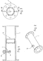
- the gas meter downstream pipe section 1 is in perspective in FIG. 2 shown.
- This can for example have a circumferentially provided connection sleeve 10 in the form of a weld-on, in which the Impfdüse 4 is inserted.
- the seed nozzle 4 includes a nozzle body inserted in or provided to the leading end of a dip tube.
- the dip tube 11 and the nozzle body may be integrally formed, but these may also be formed in several parts.
- vaccination nozzle 4 the entire arrangement consisting of immersion tube 11 and nozzle body will be referred to as vaccination nozzle 4 below.
- the dip tube 11 extends approximately into the longitudinal central axis of the pipe section 1 and the mouth of the injection nozzle 4 is aligned coaxially to the longitudinal center axis of the pipe section 1. This may, but need not, extend in the longitudinal center axis of the pipe section.
- the entire free cross section of the pipe section 1 filling cassette 12 is arranged, which encloses an evaporation body or forms an evaporation body.
- the evaporation body is not shown, only the enclosure of the evaporation body in the form of the cassette 12 is shown, which can accommodate, for example, an evaporation body in the form of a metal foam / rigid foam. In this case, only a marginal enclosure of the disc-shaped Verdunstungs stressess is required.
- the cassette 12 forms only a peripheral and peripheral enclosure.
- the cassette 12 can also be designed as a can closed on all sides and be provided with a filling, for example in the form of steel wool or the like, thus forming a total of an evaporation body according to the present invention.
- the front and rear boundaries of the cassette 12 are formed as perforated plates or sieves.
- the introduced via the Impfdüse 4 in the gas stream odorant is taken from the gas stream, so that it wets the downstream in the flow direction of evaporation body.
- About the evaporation body is a successive delivery of the odorant to the gas stream.
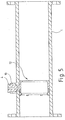
- FIG. 5 An alternative embodiment of the device which is not part of the invention is shown in FIG. 5 shown.
- FIG. 5 An alternative embodiment of the device which is not part of the invention is shown in FIG. 5 shown.
- FIG. 5 For reasons of simplification there is only a longitudinal section through the pipe section 1 according to the FIG. 4 represented, wherein the same components are provided with the same reference numerals.
- the nozzle opening of the Impfdüse 4 is aligned approximately perpendicular with respect to the imaginary longitudinal central axis of the pipe section 1 and this immediately above the evaporation body in the pipe section 1, so that the odorant emerging from the injection nozzle 4 is directly trickled into the evaporation body or into the cassette 12.
- the evaporation body (not shown) is enclosed at least peripherally by a cassette 12, the invention is to be understood that the evaporation body can be inserted directly into the pipe section 1 at the relevant point.
- the seed nozzle 4 is disposed upstream of the evaporation body and in the second embodiment, the seed nozzle 4 is arranged with respect to the gas flow at the same level with the evaporation body and above, correspond Features of the two embodiments each other, in particular, the formation of the evaporation body can be the same.
Landscapes
- Chemical & Material Sciences (AREA)
- Chemical Kinetics & Catalysis (AREA)
- Engineering & Computer Science (AREA)
- Mechanical Engineering (AREA)
- General Engineering & Computer Science (AREA)
- Dispersion Chemistry (AREA)
- Feeding, Discharge, Calcimining, Fusing, And Gas-Generation Devices (AREA)
Applications Claiming Priority (1)
| Application Number | Priority Date | Filing Date | Title |
|---|---|---|---|
| DE102014005550.7A DE102014005550B4 (de) | 2014-04-16 | 2014-04-16 | Vorrichtung und Verfahren zur Odorierung eines Gasstroms in einem Gasnetz |
Publications (2)
| Publication Number | Publication Date |
|---|---|
| EP2933015A1 EP2933015A1 (de) | 2015-10-21 |
| EP2933015B1 true EP2933015B1 (de) | 2019-03-06 |
Family
ID=52672173
Family Applications (1)
| Application Number | Title | Priority Date | Filing Date |
|---|---|---|---|
| EP15158410.9A Active EP2933015B1 (de) | 2014-04-16 | 2015-03-10 | Vorrichtung und Verfahren zur Odorierung eines Gasstroms in einem Gasnetz |
Country Status (3)
| Country | Link |
|---|---|
| EP (1) | EP2933015B1 (da) |
| DE (1) | DE102014005550B4 (da) |
| DK (1) | DK2933015T3 (da) |
Cited By (2)
| Publication number | Priority date | Publication date | Assignee | Title |
|---|---|---|---|---|
| EP3933250A1 (de) * | 2020-06-30 | 2022-01-05 | Westnetz GmbH | Einspeiseeinrichtung und vorrichtung zum einspeisen eines flüssigen odoriermittels in einen durch eine gasleitung strömenden gasstrom sowie deren verwendungen |
| WO2025216963A1 (en) * | 2024-04-09 | 2025-10-16 | Chevron Phillips Chemical Company Lp | Odorants for carbon dioxide, odorized carbon dioxide, and methods |
Families Citing this family (7)
| Publication number | Priority date | Publication date | Assignee | Title |
|---|---|---|---|---|
| DE102015217814A1 (de) * | 2015-09-17 | 2017-03-23 | Rwe Deutschland Ag | Vorrichtung zur Einspeisung eines flüssigen Odoriermittels in ein Gasnetz |
| DE102017128495A1 (de) | 2017-11-30 | 2019-06-06 | Westnetz Gmbh | Vorrichtung und Verfahren zur Odorierung eines Gasstroms in einer Gasleitung |
| DE202018103234U1 (de) * | 2018-06-08 | 2018-07-25 | Gas-Anlagenbau Petzold GmbH | Odorierungsvorrichtung, Odorierungsdüse, Wechselschleuse |
| DE102019112964A1 (de) * | 2019-05-16 | 2020-11-19 | Westnetz Gmbh | Injektionseinrichtung zur Injektion eines flüssigen Odoriermittels in einen durch eine Gasleitung strömenden Gasstrom, deren Verwendung und Verfahren zu deren Herstellung |
| CN110129095B (zh) * | 2019-06-06 | 2021-04-27 | 河南城建学院 | 一种基于煤化学链气化直接制备甲烷用装置 |
| CN116263236B (zh) * | 2021-12-14 | 2025-06-27 | 中国石油工程建设有限公司 | 一种已建天然气管道安全掺氢系统与方法 |
| DE102022116154A1 (de) * | 2022-06-29 | 2024-01-04 | Westnetz Gmbh | Vorrichtung und Verfahren zum Bereitstellen eines odorierten Erdgas- und Wasserstoff-Gemisches |
Citations (1)
| Publication number | Priority date | Publication date | Assignee | Title |
|---|---|---|---|---|
| DD59604A (da) * |
Family Cites Families (9)
| Publication number | Priority date | Publication date | Assignee | Title |
|---|---|---|---|---|
| US2279705A (en) * | 1938-08-08 | 1942-04-14 | Standard Oil Co California | Liquefied gas odorizer and method of using same |
| DE2501809A1 (de) * | 1974-01-18 | 1975-09-18 | Sun Oil Co Pennsylvania | Einspritz-vorrichtung |
| US5304327A (en) | 1992-07-13 | 1994-04-19 | Welker Engineering, Inc. | Mercaptan injection apparatus for use with a pipeline |
| RO120932B1 (ro) * | 2003-11-25 | 2006-09-29 | Ioan-Francisc Iosif-Gabriel Moisin | Instalaţie şi procedeu pentru odorizarea gazelor naturale |
| US7137569B1 (en) * | 2005-04-05 | 2006-11-21 | Kenco International, Inc. | Chemical injector |
| US7533520B2 (en) * | 2006-04-24 | 2009-05-19 | Fleetguard, Inc. | Exhaust aftertreatment mixer with stamped muffler flange |
| FR2956155B1 (fr) * | 2010-02-05 | 2013-09-13 | Peugeot Citroen Automobiles Sa | Ligne d'echappement pour un moteur a combustion interne |
| FR2957119B1 (fr) * | 2010-03-02 | 2013-05-10 | Peugeot Citroen Automobiles Sa | Chambre de melange d'un produit reducteur a des gaz d'echappement |
| EP2368625A1 (de) * | 2010-03-22 | 2011-09-28 | Sulzer Chemtech AG | Verfahren und Vorrichtung zur Dispergierung |
-
2014
- 2014-04-16 DE DE102014005550.7A patent/DE102014005550B4/de active Active
-
2015
- 2015-03-10 EP EP15158410.9A patent/EP2933015B1/de active Active
- 2015-03-10 DK DK15158410.9T patent/DK2933015T3/da active
Patent Citations (1)
| Publication number | Priority date | Publication date | Assignee | Title |
|---|---|---|---|---|
| DD59604A (da) * |
Cited By (2)
| Publication number | Priority date | Publication date | Assignee | Title |
|---|---|---|---|---|
| EP3933250A1 (de) * | 2020-06-30 | 2022-01-05 | Westnetz GmbH | Einspeiseeinrichtung und vorrichtung zum einspeisen eines flüssigen odoriermittels in einen durch eine gasleitung strömenden gasstrom sowie deren verwendungen |
| WO2025216963A1 (en) * | 2024-04-09 | 2025-10-16 | Chevron Phillips Chemical Company Lp | Odorants for carbon dioxide, odorized carbon dioxide, and methods |
Also Published As
| Publication number | Publication date |
|---|---|
| DK2933015T3 (da) | 2019-06-03 |
| DE102014005550B4 (de) | 2024-05-02 |
| EP2933015A1 (de) | 2015-10-21 |
| DE102014005550A1 (de) | 2015-10-22 |
Similar Documents
| Publication | Publication Date | Title |
|---|---|---|
| EP2933015B1 (de) | Vorrichtung und Verfahren zur Odorierung eines Gasstroms in einem Gasnetz | |
| DE2106794C3 (de) | Spender zur oralen oder nasalen Applikation von einzelnen Dosen eines fein verteilten Medikamentes | |
| DE3100001C2 (da) | ||
| EP2100659B1 (de) | Vorrichtung zum Erzeugen und Versprühen eines Aerosols | |
| EP1047488A1 (de) | Einrichtung zum einbringen eines flüssigen reduktionsmittels in eine abgas-reinigungsanlage | |
| DE602005005081T2 (de) | Durchflussgeregelter niederdruck-pulververteiler | |
| EP3717139B1 (de) | Vorrichtung und verfahren zur odorierung eines gasstroms in einer gasleitung | |
| DE102011003356A1 (de) | Vorrichtung zur Abgabe eines Reduktionsmittels in einen Abgaskanal einer Brennkraftmaschine | |
| EP3969547A1 (de) | Injektionseinrichtung zur injektion eines flüssigen odoriermittels in einen durch eine gasleitung strömenden gasstrom, deren verwendung und verfahren zu deren herstellung | |
| DE102010040365A1 (de) | Druckluftzerstäuber | |
| DE102015217814A1 (de) | Vorrichtung zur Einspeisung eines flüssigen Odoriermittels in ein Gasnetz | |
| WO2022218695A1 (de) | Inhalationsaktuator, einsatz und inhalationsvorrichtung | |
| DE1806897B2 (de) | Dosierapparat zur dosierten zugabe einer fluessigkeit in eine zweite fluessigkeit | |
| WO2009046466A1 (de) | Vorrichtung zur gaseinbringung in eine flüssigkeit | |
| CH704943B1 (de) | Zweistoff-Innenmischdüsenanordnung und Verfahren zur Zerstäubung einer Flüssigkeit. | |
| AT503643B1 (de) | Vorrichtung zur gaseinbringung in eine flüssigkeit | |
| DE3723022C2 (da) | ||
| DE2113409A1 (de) | Verfahren und Vorrichtung zum Einfuellen eines Loesungsmittels in ein Flaschenbuendel fuer Druckgas | |
| DD254173A1 (de) | Kombinierte applikation von agrochemikalien mittels fluessigapplikationsanlage an agrarluftfahrzeugen | |
| DD205336A1 (de) | Feuerloescher | |
| DE1621566C3 (de) | Vorrichtung zum Verdüsen von Antikorrosionsflüssigkeit in Brenngas-Versorgungs-Niederdruckleitungen | |
| DE112008003842B4 (de) | Verfahren und Vorrichtung zum Mischen von Fluiden an einer Breitschlitzdüse | |
| DE102022116154A1 (de) | Vorrichtung und Verfahren zum Bereitstellen eines odorierten Erdgas- und Wasserstoff-Gemisches | |
| DE2264630C3 (de) | Vorrichtung zum Ansaugen und Beimischen von Zusatzstoffen in einen Flüssigkeitsstrom einer Badearmatur o.dgl | |
| DE358722C (de) | Vorrichtung, um auf eine poroese Masse getraeufelte Medikamente mittels Dampf zu zerstaeuben |
Legal Events
| Date | Code | Title | Description |
|---|---|---|---|
| PUAI | Public reference made under article 153(3) epc to a published international application that has entered the european phase |
Free format text: ORIGINAL CODE: 0009012 |
|
| AK | Designated contracting states |
Kind code of ref document: A1 Designated state(s): AL AT BE BG CH CY CZ DE DK EE ES FI FR GB GR HR HU IE IS IT LI LT LU LV MC MK MT NL NO PL PT RO RS SE SI SK SM TR |
|
| AX | Request for extension of the european patent |
Extension state: BA ME |
|
| 17P | Request for examination filed |
Effective date: 20160420 |
|
| RBV | Designated contracting states (corrected) |
Designated state(s): AL AT BE BG CH CY CZ DE DK EE ES FI FR GB GR HR HU IE IS IT LI LT LU LV MC MK MT NL NO PL PT RO RS SE SI SK SM TR |
|
| STAA | Information on the status of an ep patent application or granted ep patent |
Free format text: STATUS: EXAMINATION IS IN PROGRESS |
|
| 17Q | First examination report despatched |
Effective date: 20170213 |
|
| GRAP | Despatch of communication of intention to grant a patent |
Free format text: ORIGINAL CODE: EPIDOSNIGR1 |
|
| STAA | Information on the status of an ep patent application or granted ep patent |
Free format text: STATUS: GRANT OF PATENT IS INTENDED |
|
| INTG | Intention to grant announced |
Effective date: 20181001 |
|
| GRAS | Grant fee paid |
Free format text: ORIGINAL CODE: EPIDOSNIGR3 |
|
| GRAA | (expected) grant |
Free format text: ORIGINAL CODE: 0009210 |
|
| STAA | Information on the status of an ep patent application or granted ep patent |
Free format text: STATUS: THE PATENT HAS BEEN GRANTED |
|
| AK | Designated contracting states |
Kind code of ref document: B1 Designated state(s): AL AT BE BG CH CY CZ DE DK EE ES FI FR GB GR HR HU IE IS IT LI LT LU LV MC MK MT NL NO PL PT RO RS SE SI SK SM TR |
|
| REG | Reference to a national code |
Ref country code: GB Ref legal event code: FG4D Free format text: NOT ENGLISH |
|
| REG | Reference to a national code |
Ref country code: CH Ref legal event code: EP Ref country code: AT Ref legal event code: REF Ref document number: 1103802 Country of ref document: AT Kind code of ref document: T Effective date: 20190315 |
|
| REG | Reference to a national code |
Ref country code: DE Ref legal event code: R096 Ref document number: 502015008194 Country of ref document: DE |
|
| REG | Reference to a national code |
Ref country code: IE Ref legal event code: FG4D Free format text: LANGUAGE OF EP DOCUMENT: GERMAN |
|
| REG | Reference to a national code |
Ref country code: CH Ref legal event code: NV Representative=s name: DENNEMEYER AG, CH |
|
| REG | Reference to a national code |
Ref country code: DK Ref legal event code: T3 Effective date: 20190528 |
|
| REG | Reference to a national code |
Ref country code: NL Ref legal event code: FP |
|
| REG | Reference to a national code |
Ref country code: LT Ref legal event code: MG4D |
|
| PG25 | Lapsed in a contracting state [announced via postgrant information from national office to epo] |
Ref country code: LT Free format text: LAPSE BECAUSE OF FAILURE TO SUBMIT A TRANSLATION OF THE DESCRIPTION OR TO PAY THE FEE WITHIN THE PRESCRIBED TIME-LIMIT Effective date: 20190306 Ref country code: SE Free format text: LAPSE BECAUSE OF FAILURE TO SUBMIT A TRANSLATION OF THE DESCRIPTION OR TO PAY THE FEE WITHIN THE PRESCRIBED TIME-LIMIT Effective date: 20190306 Ref country code: NO Free format text: LAPSE BECAUSE OF FAILURE TO SUBMIT A TRANSLATION OF THE DESCRIPTION OR TO PAY THE FEE WITHIN THE PRESCRIBED TIME-LIMIT Effective date: 20190606 Ref country code: FI Free format text: LAPSE BECAUSE OF FAILURE TO SUBMIT A TRANSLATION OF THE DESCRIPTION OR TO PAY THE FEE WITHIN THE PRESCRIBED TIME-LIMIT Effective date: 20190306 |
|
| PG25 | Lapsed in a contracting state [announced via postgrant information from national office to epo] |
Ref country code: GR Free format text: LAPSE BECAUSE OF FAILURE TO SUBMIT A TRANSLATION OF THE DESCRIPTION OR TO PAY THE FEE WITHIN THE PRESCRIBED TIME-LIMIT Effective date: 20190607 Ref country code: HR Free format text: LAPSE BECAUSE OF FAILURE TO SUBMIT A TRANSLATION OF THE DESCRIPTION OR TO PAY THE FEE WITHIN THE PRESCRIBED TIME-LIMIT Effective date: 20190306 Ref country code: BG Free format text: LAPSE BECAUSE OF FAILURE TO SUBMIT A TRANSLATION OF THE DESCRIPTION OR TO PAY THE FEE WITHIN THE PRESCRIBED TIME-LIMIT Effective date: 20190606 Ref country code: LV Free format text: LAPSE BECAUSE OF FAILURE TO SUBMIT A TRANSLATION OF THE DESCRIPTION OR TO PAY THE FEE WITHIN THE PRESCRIBED TIME-LIMIT Effective date: 20190306 Ref country code: RS Free format text: LAPSE BECAUSE OF FAILURE TO SUBMIT A TRANSLATION OF THE DESCRIPTION OR TO PAY THE FEE WITHIN THE PRESCRIBED TIME-LIMIT Effective date: 20190306 |
|
| PG25 | Lapsed in a contracting state [announced via postgrant information from national office to epo] |
Ref country code: SK Free format text: LAPSE BECAUSE OF FAILURE TO SUBMIT A TRANSLATION OF THE DESCRIPTION OR TO PAY THE FEE WITHIN THE PRESCRIBED TIME-LIMIT Effective date: 20190306 Ref country code: RO Free format text: LAPSE BECAUSE OF FAILURE TO SUBMIT A TRANSLATION OF THE DESCRIPTION OR TO PAY THE FEE WITHIN THE PRESCRIBED TIME-LIMIT Effective date: 20190306 Ref country code: CZ Free format text: LAPSE BECAUSE OF FAILURE TO SUBMIT A TRANSLATION OF THE DESCRIPTION OR TO PAY THE FEE WITHIN THE PRESCRIBED TIME-LIMIT Effective date: 20190306 Ref country code: ES Free format text: LAPSE BECAUSE OF FAILURE TO SUBMIT A TRANSLATION OF THE DESCRIPTION OR TO PAY THE FEE WITHIN THE PRESCRIBED TIME-LIMIT Effective date: 20190306 Ref country code: PT Free format text: LAPSE BECAUSE OF FAILURE TO SUBMIT A TRANSLATION OF THE DESCRIPTION OR TO PAY THE FEE WITHIN THE PRESCRIBED TIME-LIMIT Effective date: 20190706 Ref country code: AL Free format text: LAPSE BECAUSE OF FAILURE TO SUBMIT A TRANSLATION OF THE DESCRIPTION OR TO PAY THE FEE WITHIN THE PRESCRIBED TIME-LIMIT Effective date: 20190306 Ref country code: IT Free format text: LAPSE BECAUSE OF FAILURE TO SUBMIT A TRANSLATION OF THE DESCRIPTION OR TO PAY THE FEE WITHIN THE PRESCRIBED TIME-LIMIT Effective date: 20190306 Ref country code: EE Free format text: LAPSE BECAUSE OF FAILURE TO SUBMIT A TRANSLATION OF THE DESCRIPTION OR TO PAY THE FEE WITHIN THE PRESCRIBED TIME-LIMIT Effective date: 20190306 |
|
| PG25 | Lapsed in a contracting state [announced via postgrant information from national office to epo] |
Ref country code: PL Free format text: LAPSE BECAUSE OF FAILURE TO SUBMIT A TRANSLATION OF THE DESCRIPTION OR TO PAY THE FEE WITHIN THE PRESCRIBED TIME-LIMIT Effective date: 20190306 Ref country code: SM Free format text: LAPSE BECAUSE OF FAILURE TO SUBMIT A TRANSLATION OF THE DESCRIPTION OR TO PAY THE FEE WITHIN THE PRESCRIBED TIME-LIMIT Effective date: 20190306 |
|
| REG | Reference to a national code |
Ref country code: DE Ref legal event code: R097 Ref document number: 502015008194 Country of ref document: DE |
|
| PG25 | Lapsed in a contracting state [announced via postgrant information from national office to epo] |
Ref country code: IS Free format text: LAPSE BECAUSE OF FAILURE TO SUBMIT A TRANSLATION OF THE DESCRIPTION OR TO PAY THE FEE WITHIN THE PRESCRIBED TIME-LIMIT Effective date: 20190706 |
|
| PLBE | No opposition filed within time limit |
Free format text: ORIGINAL CODE: 0009261 |
|
| STAA | Information on the status of an ep patent application or granted ep patent |
Free format text: STATUS: NO OPPOSITION FILED WITHIN TIME LIMIT |
|
| PG25 | Lapsed in a contracting state [announced via postgrant information from national office to epo] |
Ref country code: MC Free format text: LAPSE BECAUSE OF FAILURE TO SUBMIT A TRANSLATION OF THE DESCRIPTION OR TO PAY THE FEE WITHIN THE PRESCRIBED TIME-LIMIT Effective date: 20190306 Ref country code: IE Free format text: LAPSE BECAUSE OF NON-PAYMENT OF DUE FEES Effective date: 20190310 |
|
| 26N | No opposition filed |
Effective date: 20191209 |
|
| PG25 | Lapsed in a contracting state [announced via postgrant information from national office to epo] |
Ref country code: SI Free format text: LAPSE BECAUSE OF FAILURE TO SUBMIT A TRANSLATION OF THE DESCRIPTION OR TO PAY THE FEE WITHIN THE PRESCRIBED TIME-LIMIT Effective date: 20190306 |
|
| PG25 | Lapsed in a contracting state [announced via postgrant information from national office to epo] |
Ref country code: TR Free format text: LAPSE BECAUSE OF FAILURE TO SUBMIT A TRANSLATION OF THE DESCRIPTION OR TO PAY THE FEE WITHIN THE PRESCRIBED TIME-LIMIT Effective date: 20190306 |
|
| PG25 | Lapsed in a contracting state [announced via postgrant information from national office to epo] |
Ref country code: MT Free format text: LAPSE BECAUSE OF FAILURE TO SUBMIT A TRANSLATION OF THE DESCRIPTION OR TO PAY THE FEE WITHIN THE PRESCRIBED TIME-LIMIT Effective date: 20190306 |
|
| PG25 | Lapsed in a contracting state [announced via postgrant information from national office to epo] |
Ref country code: CY Free format text: LAPSE BECAUSE OF FAILURE TO SUBMIT A TRANSLATION OF THE DESCRIPTION OR TO PAY THE FEE WITHIN THE PRESCRIBED TIME-LIMIT Effective date: 20190306 |
|
| PG25 | Lapsed in a contracting state [announced via postgrant information from national office to epo] |
Ref country code: HU Free format text: LAPSE BECAUSE OF FAILURE TO SUBMIT A TRANSLATION OF THE DESCRIPTION OR TO PAY THE FEE WITHIN THE PRESCRIBED TIME-LIMIT; INVALID AB INITIO Effective date: 20150310 |
|
| REG | Reference to a national code |
Ref country code: DE Ref legal event code: R079 Ref document number: 502015008194 Country of ref document: DE Free format text: PREVIOUS MAIN CLASS: B01F0005040000 Ipc: B01F0025300000 |
|
| PG25 | Lapsed in a contracting state [announced via postgrant information from national office to epo] |
Ref country code: MK Free format text: LAPSE BECAUSE OF FAILURE TO SUBMIT A TRANSLATION OF THE DESCRIPTION OR TO PAY THE FEE WITHIN THE PRESCRIBED TIME-LIMIT Effective date: 20190306 |
|
| PGFP | Annual fee paid to national office [announced via postgrant information from national office to epo] |
Ref country code: CH Payment date: 20250401 Year of fee payment: 11 |
|
| REG | Reference to a national code |
Ref country code: CH Ref legal event code: U11 Free format text: ST27 STATUS EVENT CODE: U-0-0-U10-U11 (AS PROVIDED BY THE NATIONAL OFFICE) Effective date: 20260401 |
|
| PGFP | Annual fee paid to national office [announced via postgrant information from national office to epo] |
Ref country code: GB Payment date: 20260324 Year of fee payment: 12 |
|
| PGFP | Annual fee paid to national office [announced via postgrant information from national office to epo] |
Ref country code: DE Payment date: 20260320 Year of fee payment: 12 Ref country code: DK Payment date: 20260323 Year of fee payment: 12 |
|
| PGFP | Annual fee paid to national office [announced via postgrant information from national office to epo] |
Ref country code: AT Payment date: 20260319 Year of fee payment: 12 |
|
| PGFP | Annual fee paid to national office [announced via postgrant information from national office to epo] |
Ref country code: LU Payment date: 20260320 Year of fee payment: 12 Ref country code: BE Payment date: 20260323 Year of fee payment: 12 |
|
| PGFP | Annual fee paid to national office [announced via postgrant information from national office to epo] |
Ref country code: NL Payment date: 20260323 Year of fee payment: 12 |
|
| PGFP | Annual fee paid to national office [announced via postgrant information from national office to epo] |
Ref country code: FR Payment date: 20260324 Year of fee payment: 12 |