EP2933038A1 - Dispositif pour former un élément de forgeage de finition pour un vilebrequin forgé de moteur à 3 cylindres et procédé de production d'un vilebrequin forgé de moteur à 3 cylindres qui utilise ce dispositif - Google Patents
Dispositif pour former un élément de forgeage de finition pour un vilebrequin forgé de moteur à 3 cylindres et procédé de production d'un vilebrequin forgé de moteur à 3 cylindres qui utilise ce dispositif Download PDFInfo
- Publication number
- EP2933038A1 EP2933038A1 EP13862380.6A EP13862380A EP2933038A1 EP 2933038 A1 EP2933038 A1 EP 2933038A1 EP 13862380 A EP13862380 A EP 13862380A EP 2933038 A1 EP2933038 A1 EP 2933038A1
- Authority
- EP
- European Patent Office
- Prior art keywords
- crank pin
- rough
- dies
- portions
- blank
- Prior art date
- Legal status (The legal status is an assumption and is not a legal conclusion. Google has not performed a legal analysis and makes no representation as to the accuracy of the status listed.)
- Granted
Links
Images








Classifications
-
- B—PERFORMING OPERATIONS; TRANSPORTING
- B21—MECHANICAL METAL-WORKING WITHOUT ESSENTIALLY REMOVING MATERIAL; PUNCHING METAL
- B21K—MAKING FORGED OR PRESSED METAL PRODUCTS, e.g. HORSE-SHOES, RIVETS, BOLTS OR WHEELS
- B21K1/00—Making machine elements
- B21K1/06—Making machine elements axles or shafts
- B21K1/08—Making machine elements axles or shafts crankshafts
-
- B—PERFORMING OPERATIONS; TRANSPORTING
- B21—MECHANICAL METAL-WORKING WITHOUT ESSENTIALLY REMOVING MATERIAL; PUNCHING METAL
- B21J—FORGING; HAMMERING; PRESSING METAL; RIVETING; FORGE FURNACES
- B21J1/00—Preparing metal stock or similar ancillary operations prior, during or post forging, e.g. heating or cooling
- B21J1/04—Shaping in the rough solely by forging or pressing
-
- B—PERFORMING OPERATIONS; TRANSPORTING
- B21—MECHANICAL METAL-WORKING WITHOUT ESSENTIALLY REMOVING MATERIAL; PUNCHING METAL
- B21J—FORGING; HAMMERING; PRESSING METAL; RIVETING; FORGE FURNACES
- B21J13/00—Details of machines for forging, pressing, or hammering
- B21J13/02—Dies or mountings therefor
-
- B—PERFORMING OPERATIONS; TRANSPORTING
- B21—MECHANICAL METAL-WORKING WITHOUT ESSENTIALLY REMOVING MATERIAL; PUNCHING METAL
- B21J—FORGING; HAMMERING; PRESSING METAL; RIVETING; FORGE FURNACES
- B21J13/00—Details of machines for forging, pressing, or hammering
- B21J13/02—Dies or mountings therefor
- B21J13/025—Dies with parts moving along auxiliary lateral directions
-
- B—PERFORMING OPERATIONS; TRANSPORTING
- B21—MECHANICAL METAL-WORKING WITHOUT ESSENTIALLY REMOVING MATERIAL; PUNCHING METAL
- B21J—FORGING; HAMMERING; PRESSING METAL; RIVETING; FORGE FURNACES
- B21J5/00—Methods for forging, hammering, or pressing; Special equipment or accessories therefor
- B21J5/02—Die forging; Trimming by making use of special dies ; Punching during forging
- B21J5/025—Closed die forging
-
- B—PERFORMING OPERATIONS; TRANSPORTING
- B21—MECHANICAL METAL-WORKING WITHOUT ESSENTIALLY REMOVING MATERIAL; PUNCHING METAL
- B21J—FORGING; HAMMERING; PRESSING METAL; RIVETING; FORGE FURNACES
- B21J9/00—Forging presses
-
- B—PERFORMING OPERATIONS; TRANSPORTING
- B21—MECHANICAL METAL-WORKING WITHOUT ESSENTIALLY REMOVING MATERIAL; PUNCHING METAL
- B21J—FORGING; HAMMERING; PRESSING METAL; RIVETING; FORGE FURNACES
- B21J9/00—Forging presses
- B21J9/02—Special design or construction
- B21J9/027—Special design or construction with punches moving along auxiliary lateral directions
-
- F—MECHANICAL ENGINEERING; LIGHTING; HEATING; WEAPONS; BLASTING
- F16—ENGINEERING ELEMENTS AND UNITS; GENERAL MEASURES FOR PRODUCING AND MAINTAINING EFFECTIVE FUNCTIONING OF MACHINES OR INSTALLATIONS; THERMAL INSULATION IN GENERAL
- F16C—SHAFTS; FLEXIBLE SHAFTS; ELEMENTS OR CRANKSHAFT MECHANISMS; ROTARY BODIES OTHER THAN GEARING ELEMENTS; BEARINGS
- F16C2220/00—Shaping
- F16C2220/40—Shaping by deformation without removing material
- F16C2220/46—Shaping by deformation without removing material by forging
-
- F—MECHANICAL ENGINEERING; LIGHTING; HEATING; WEAPONS; BLASTING
- F16—ENGINEERING ELEMENTS AND UNITS; GENERAL MEASURES FOR PRODUCING AND MAINTAINING EFFECTIVE FUNCTIONING OF MACHINES OR INSTALLATIONS; THERMAL INSULATION IN GENERAL
- F16C—SHAFTS; FLEXIBLE SHAFTS; ELEMENTS OR CRANKSHAFT MECHANISMS; ROTARY BODIES OTHER THAN GEARING ELEMENTS; BEARINGS
- F16C3/00—Shafts; Axles; Cranks; Eccentrics
- F16C3/04—Crankshafts, eccentric-shafts; Cranks, eccentrics
- F16C3/06—Crankshafts
- F16C3/08—Crankshafts made in one piece
-
- Y—GENERAL TAGGING OF NEW TECHNOLOGICAL DEVELOPMENTS; GENERAL TAGGING OF CROSS-SECTIONAL TECHNOLOGIES SPANNING OVER SEVERAL SECTIONS OF THE IPC; TECHNICAL SUBJECTS COVERED BY FORMER USPC CROSS-REFERENCE ART COLLECTIONS [XRACs] AND DIGESTS
- Y10—TECHNICAL SUBJECTS COVERED BY FORMER USPC
- Y10T—TECHNICAL SUBJECTS COVERED BY FORMER US CLASSIFICATION
- Y10T29/00—Metal working
- Y10T29/17—Crankshaft making apparatus
-
- Y—GENERAL TAGGING OF NEW TECHNOLOGICAL DEVELOPMENTS; GENERAL TAGGING OF CROSS-SECTIONAL TECHNOLOGIES SPANNING OVER SEVERAL SECTIONS OF THE IPC; TECHNICAL SUBJECTS COVERED BY FORMER USPC CROSS-REFERENCE ART COLLECTIONS [XRACs] AND DIGESTS
- Y10—TECHNICAL SUBJECTS COVERED BY FORMER USPC
- Y10T—TECHNICAL SUBJECTS COVERED BY FORMER US CLASSIFICATION
- Y10T29/00—Metal working
- Y10T29/49—Method of mechanical manufacture
- Y10T29/49229—Prime mover or fluid pump making
- Y10T29/49286—Crankshaft making
Definitions
- the present invention relates to techniques for manufacturing, by hot forging, a crankshaft (hereinafter also referred to as a "forged crankshaft") for a three-cylinder engine.
- the present invention relates to an apparatus for forming, in the process of manufacturing a forged crankshaft, a blank for finish forging to be subjected to finish forging by which a final shape of the forged crankshaft is obtained, and a method for manufacturing a forged crankshaft for a three-cylinder engine including preforming steps using such forming apparatus.
- crankshaft In engines of passenger cars, motorcycles, agricultural machines, and the like, a crankshaft is required for taking out power by converting reciprocating motion of pistons to rotary motion.
- crankshafts there are two types of crankshafts: those that are manufactured by forging and those that are manufactured by casting, and the former forged crankshafts superior in terms of strength and stiffness are more widely used.
- downsizing of engine displacement becomes popular, and a three-cylinder engine is attracting wide attention.
- forged crankshafts for three-cylinder engines are manufactured by using, as a starting material, a billet having a circular or square cross section and having a constant cross-sectional area along the entire length, and subjecting the billet to the steps of preforming, die forging, trimming and coining in order.
- the preforming step includes roll forming and bending (so called "preforming")
- the die forging step includes block forging and finish forging.
- FIG. 1 is a schematic diagram illustrating a typical conventional process for manufacturing a forged crankshaft for a three-cylinder engine.
- a crankshaft 1 illustrated in FIG. 1 is to be mounted in a three-cylinder engine. It is a three-cylinder four-counterweight crankshaft that includes: four journals J1 to J4; three crank pins P1 to P3; a front part Fr; a flange Fl; and six crank arms (hereinafter referred to as "arms" to be simple) A1 to A6 that alternatively connect the journals J1 to J4 and the crank pins P1 to P3 to each other, wherein among the six arms A1 to A6, first and second arms A1 and A2, and fifth and sixth arms A5 and A6 respectively connecting to first and third crank pins P1 and P3 at opposite ends, have balance weights.
- the forged crankshaft 1 is manufactured in the following manner. Firstly, a billet 2 shown in FIG. 1(a) , which has been previously cut to a predetermined length, is heated by an induction heater or a gas atmosphere furnace and then is subjected to roll forming. In the roll forming step, the billet 2 is rolled and reduced in cross section by grooved rolls, for example, to distribute its volume in the longitudinal direction, whereby a rolled blank 103, which is an intermediate material, is formed (see FIG. 1 (b) ).
- the rolled blank 103 obtained by the roll forming is partially pressed in a press in a direction perpendicular to the longitudinal direction to distribute its volume, whereby a bent blank 104, which is a secondary intermediate material, is formed (see FIG. 1(c) ).
- the bent blank 104 obtained by bending is press forged with a pair of upper and lower dies, whereby a forged blank 105 having a general shape of a crankshaft (forged final product) is formed (see FIG. 1(d) ).
- the finish forging step the block forged blank 105 obtained by the block forging is further processed by press forging the block forged blank 105 with a pair of upper and lower dies, whereby a forged blank 106 having a shape in agreement with the shape of the crankshaft is formed (see FIG. 1(e) ).
- excess material flows out as a flash from between the parting surfaces of the dies that oppose each other.
- the block forged blank 105 and the finish forged blank 106 have large flashes 105a and 106a, respectively, around the formed shape of the crankshaft.
- the finish forged blank 106 with the flash 106a obtained by the finish forging, is held by dies from above and below and the flash 106a is trimmed by a cutting die.
- the forged crankshaft 1 is obtained as shown in FIG. 1(f) .
- principal parts of the forged crankshaft 1, from which the flash has been removed e.g., shaft parts such as the journals J, the crank pins P, the front part Fr, and the flange Fl, and in some cases the arms A, are slightly pressed with dies from above and below and formed into a desired size and shape.
- the forged crankshaft 1 is manufactured.
- the manufacturing process shown in FIG. 1 is applicable not only to a three-cylinder four-counterweight crankshaft as exemplified, but also to a three-cylinder six-counterweight crankshaft in which, all six arms A have balance weights. It should be noted that, when adjustment of a placement angle of the crank pins is necessary, a step of twisting is added after the trimming step.
- Patent Literature 1 discloses a technique for manufacturing a crankshaft, the technique including: using, as a blank, a stepped round bar having reduced diameter regions at portions to be formed into journals and crank pins of a crankshaft; holding, with dies, a pair of the portions to be formed into journals, between which a portion to be formed into a crank pin is disposed and, in this state, axially moving the opposing dies toward each other to compressively deform the round bar blank; pressing punches against the portion to be formed into a crank pin in a direction perpendicular to the axial direction to place the portion to be formed into a crank pin into an eccentric position; and repeating the above operations in succession for all crank throws, whereby the journals and the crank pins are shaped and the arms are roughly shaped.
- Patent Literature 2 discloses a technique for manufacturing a crankshaft, the technique including: using, as a blank, a simple round bar; holding one end of the two ends of the round bar with a stationary die and the other end thereof with a movable die, and holding portions to be formed into journals with journal dies and portions to be formed into crank pins with crank pin dies; in this state, axially moving the movable die, the journal dies, and the crank pin dies toward the stationary die to compressively deform the round bar blank; and moving the crank pin dies in an eccentric direction perpendicular to the axial direction to place the portion to be formed into the crank pin into an eccentric position, whereby the journals and the crank pins are shaped and the arms are roughly shaped.
- the shape of arms is formed by free expansion of a round bar blank in a direction perpendicular to the axial direction in conjunction with its axial compressive deformation and by tensile deformation of the round bar blank in conjunction with the movement of portions to be formed into crank pins in an eccentric direction. Because of this, the contour shape of the arms tend to be unstable, and thus dimensional accuracy cannot be ensured.
- the present invention has been made in view of the above-mentioned problems. Accordingly, in order to manufacture forged crankshafts for three-cylinder engines with high material utilization and also with high dimensional accuracy regardless of their shapes, it is an object of the present invention to provide an apparatus for use in forming a blank for finish forging to be subjected to finish forging on the premise that, in the process of manufacturing the forged crankshaft, finish forging for forming its final shape is performed. Further, it is another object of the present invention to provide a method for manufacturing forged crankshafts for three-cylinder engines with high material utilization and also with high dimensional accuracy regardless of their shapes.
- the present invention is directed to an apparatus for forming a blank for finish forging for a forged crankshaft for a three-cylinder engine as set forth in (1) and (2) below and a method for manufacturing a forged crankshaft for a three-cylinder engine as set forth in (3) to (6) below.
- a forming apparatus is an apparatus for forming, in the process of manufacturing the forged crankshaft for a three-cylinder engine, the blank for finish forging to be subjected to finish forging by which a final shape of the forged crankshaft is formed, from a preform blank including: rough journal portions having an axial length equal to an axial length of journals of the forged crankshaft; rough crank pin portions having an axial length equal to an axial length of crank pins of the forged crankshaft; and rough crank arm portions having an axial thickness greater than an axial thickness of crank arms of the forged crankshaft.
- the apparatus has a configuration described below.
- the forming apparatus includes a reference crank pin die, movable crank pin dies, and journal dies, described below.
- the reference crank pin die is disposed at a location of one rough crank pin portion among the rough crank pin portions, configured to be brought into contact with such rough crank pin portion, and configured to move in the direction perpendicular to the axial direction, but be constrained from moving in the axial direction, while being in contact with side surfaces of rough crank arm portions through which the rough crank arm portions connect with such rough crank pin portion.
- the movable crank pin dies are disposed at locations of the corresponding rough crank pin portions except the one being in contact with the reference crank pin die, configured to be brought into contact with such rough crank pin portions, and configured to move axially toward the reference crank pin die and in the direction perpendicular to the axial direction, while being in contact with side surfaces of the rough crank arm portions through which the rough crank arm portions connect with such rough crank pin portions.
- the journal dies are disposed at locations of the corresponding rough journal portions, configured to hold and retain such rough journal portions therebetween in the direction perpendicular to the axial direction, and configured to move axially toward the reference crank pin die while being in contact with side surfaces of the rough crank arm portions through which the rough crank arm portions connect with such rough journal portions.
- the forming apparatus is configured such that in a state that the rough journal portions are held and retained by the journal dies and the rough crank pin portions are contacted with the reference crank pin die and the movable crank pin dies, the journal dies are moved axially, the movable crank pin dies are moved axially and in the direction perpendicular to the axial direction, and the reference crank pin die is moved in the direction perpendicular to the axial direction, thereby compressing the rough crank arm portions in the axial direction so as to reduce the thickness thereof to the thickness of crank arms of the forged crankshaft, and pressing the rough crank pin portions in the direction perpendicular to the axial direction so as to increase the amount of eccentricity thereof to the amount of eccentricity of the crank pins of the forged crankshaft.
- the reference crank pin die and the movable crank pin dies each includes an auxiliary crank pin die disposed at a location outside of the corresponding rough crank pin portion, opposite to the side where the reference crank pin die and the movable crank pin dies are contacted, and in conjunction with the axial movement of the journal dies as well as that of the movable crank pin dies and the auxiliary crank pin dies forming pairs therewith, a movement of the crank pin dies in the direction perpendicular to the axial direction is controlled in a manner that the rough crank pin portions to be deformed by pressing reach to the auxiliary crank pin dies after spaces between the journal dies, the reference crank pin die, the movable crank pin dies, and the auxiliary crank pin dies are filled.
- This forming apparatus preferably has a configuration such that, provided that a total length of movement of the reference crank pin die and the movable crank pin dies in the direction perpendicular to the axial direction is a 100% length of movement thereof, when the axial movement of the journal dies that are adjacent to such crank pin dies is completed, a length of movement of such crank pin dies in the direction perpendicular to the axial direction is 90% or less of the total length of movement, and thereafter, the movement of such crank pin dies in the direction perpendicular to the axial direction is completed.
- the above forming apparatus in (1) may have a configuration such that the reference crank pin die, the movable crank pin dies, and the journal dies are mounted on a press machine that is capable of being moved downward along the direction perpendicular to the axial direction and, by the downward movement of the press machine, the journal dies are caused to hold and retain the rough journal portions therebetween while the reference crank pin die and the movable crank pin dies are brought into contact with the rough crank pin portions, and with continued downward movement of the press machine, the journal dies are moved axially by wedge mechanisms, and the movable crank pin dies are caused to move axially by the movement of the journal dies.
- the wedge mechanisms have different wedge angles for each journal die.
- the reference crank pin die and the movable crank pin dies are coupled to hydraulic cylinders and caused to move in the direction perpendicular to the axial direction by driving the hydraulic cylinders.
- first and third rough crank pin portions at opposite ends have an amount of eccentricity in a direction perpendicular to an axial direction in the opposite direction to each other, the amount of eccentricity thereof being less than a ⁇ 3/2 of an amount of eccentricity of the crank pins of the forged crankshaft, and a second rough crank pin portion in the center has an amount of eccentricity in the direction perpendicular to the axial direction of zero or has the same amount of eccentricity in a direction perpendicular to an eccentric direction of the first and third rough crank pin portions as an amount of eccentricity of the crank pin of the forged crankshaft.
- the forming apparatus includes a reference crank pin die, movable crank pin dies, and journal dies, described below.
- the reference crank pin die is disposed at a location of the second rough crank pin portion, configured to be brought into contact with the second rough crank pin portion, and configured to be constrained from moving in the axial direction while, being in contact with side surfaces of rough crank arm portions through which the rough crank arm portions connect with the second rough crank pin portion.
- the movable crank pin dies are disposed at locations of the corresponding first and third rough crank pin portions, configured to be brought into contact with the first and third rough crank pin portions, and configured to move axially toward the reference crank pin die and in the direction perpendicular to the axial direction, while being in contact with side surfaces of the rough crank arm portions through which the rough crank arm portions connect with the first and third rough crank pin portions.
- the journal dies are disposed at locations of the corresponding rough journal portions, configured to hold and retain such rough journal portions therebetween in the direction perpendicular to the axial direction, and configured to move axially toward the reference crank pin die while being in contact with side surfaces of the rough crank arm portions through which the rough crank arm portions connect with such rough journal portions.
- the forming apparatus is configured such that in a state that the rough journal portions are held and retained by the journal dies and the rough crank pin portions are contacted with the reference crank pin die and the movable crank pin dies, the journal dies are moved axially and the movable crank pin dies are moved axially and in the direction perpendicular to the axial direction, thereby compressing the rough crank arm portions in the axial direction so as to reduce the thickness thereof to the thickness of crank arms of a forged crankshaft, and pressing the first and third rough crank pin portions in the direction perpendicular to the axial direction, but in the opposite direction to each other, so as to increase the amount of eccentricity thereof to the ⁇ 3/2 of the amount of eccentricity of crank pins of the forged crankshaft.
- a method for manufacturing a forged crankshaft for a three-cylinder engine includes the following successive steps comprising a first preforming step, a second preforming step, and a finish forging step.
- the first preforming step forms, as the preform blank to be supplied to the above forming apparatus in (1), a preform blank in which first and third rough crank pin portions at opposite ends among the rough crank pin portions have an amount of eccentricity in a direction perpendicular to an axial direction in the opposite direction to each other, the amount of eccentricity thereof being equal to a ⁇ 3/2 of an amount of eccentricity of crank pins of the forged crankshaft, and a second rough crank pin portion in the center has a smaller amount of eccentricity in the direction perpendicular to the axial direction in the direction perpendicular to an eccentric direction of the first and third rough crank pin portions than an amount of eccentricity of the crank pin of the forged crankshaft.
- the second preforming step forms, as the blank for finish forging, a blank for finish forging in which a final shape of the forged crankshaft is formed including a placement angle of the crank pins using the above forming apparatus described in (1).
- finish forging is performed on the blank for finish forging to form a forged product having the final shape of the forged crankshaft including the placement angle of the crank pins.
- a method for manufacturing a forged crankshaft for a three-cylinder engine includes the following successive steps comprising a first preforming step, a second preforming step, a finish forging step, and a twisting step.
- the first preforming step forms, as the preform blank to be supplied to the above forming apparatus in (1), a preform blank in which first and third rough crank pin portions at opposite ends among the rough crank pin portions have a smaller amount of eccentricity in a direction perpendicular to an axial direction in the same direction than an amount of eccentricity of crank pins of the forged crankshaft, and a second rough crank pin portion in the center has a smaller amount of eccentricity in the direction perpendicular to the axial direction in the direction opposite to an eccentric direction of the first and third rough crank pin portions than an amount of eccentricity of the crank pin of the forged crankshaft.
- the second preforming step forms, as the blank for finish forging, a blank for finish forging in which a final shape of the forged crankshaft is formed excluding a placement angle of the crank pins using the above forming apparatus in (1).
- finish forging is performed on the blank for finish forging to form a forged product having the final shape of the forged crankshaft excluding the placement angle of the crank pins.
- the placement angle of the crank pins of the forged product is adjusted to the placement angle of the crank pins of the forged crankshaft.
- a method for manufacturing a forged crankshaft for a three-cylinder engine includes the following successive steps comprising a first preforming step, a second preforming step, and a finish forging step.
- the first preforming step forms, as the preform blank to be supplied to the above forming apparatus in (2), a preform blank in which first and third rough crank pin portions at opposite ends among the rough crank pin portions have an amount of eccentricity in a direction perpendicular to an axial direction in the opposite direction to each other, the amount of eccentricity thereof being less than a ⁇ 3/2 of an amount of eccentricity of the crank pins of the forged crankshaft, and a second rough crank pin portion in the center has an amount of eccentricity in the direction perpendicular to the axial direction of zero.
- the second preforming step forms, using the above forming apparatus described in (2), as the blank for finish forging, a blank for finish forging in which the first and third rough crank pin portions at opposite ends among the rough crank pin portions have an amount of eccentricity in the direction perpendicular to the axial direction in the opposite direction to each other, the amount of eccentricity thereof being equal to the ⁇ 3/2 of the amount of eccentricity of the crank pins of the forged crankshaft, and the second rough crank pin portion in the center remains the same amount of eccentricity in the direction perpendicular to the axial direction as the preform blank.
- finish forging is performed on the blank for finish forging in a state that the first and third rough crank pin portions at opposite ends are horizontally placed, whereby all the rough crank pin portions are pressed in the direction perpendicular to the axial direction to form a forged product having a final shape of the forged crankshaft including a placement angle of the crank pins.
- a method for manufacturing a forged crankshaft for a three-cylinder engine includes the following successive steps comprising a first preforming step, a second preforming step, and a finish forging step.
- the first preforming step forms, as the preform blank to be supplied to the above forming apparatus in (2), a preform blank in which first and third rough crank pin portions at opposite ends among the rough crank pin portions have an amount of eccentricity in a direction perpendicular to an axial direction in the opposite direction to each other, the amount of eccentricity thereof being less than a ⁇ 3/2 of an amount of eccentricity of the crank pins of the forged crankshaft, and a second rough crank pin portion in the center has an amount of eccentricity in the direction perpendicular to the axial direction in the direction perpendicular to an eccentric direction of the first and third rough crank pin portions, the amount of eccentricity thereof being the same as an amount of eccentricity of the crank pin of the forged crankshaft.
- the second preforming step forms, using the above forming apparatus described in (2), as the blank for finish forging, a blank for finish forging in which the first and third rough crank pin portions at opposite ends among the rough crank pin portions have an amount of eccentricity in the direction perpendicular to the axial direction in the opposite direction to each other, the amount of eccentricity thereof being equal to the ⁇ 3/2 of the amount of eccentricity of the crank pins of the forged crankshaft, and the second rough crank pin portion in the center remains the same amount of eccentricity in the direction perpendicular to the axial direction as the preform blank.
- finish forging is performed on the blank for finish forging in a state that the first and third rough crank pin portions at opposite ends are horizontally placed, whereby the first and third rough crank pin portions are pressed in the direction perpendicular to the axial direction to form a forged product having a final shape of the forged crankshaft including a placement angle of the crank pins.
- a blank for finish forging without a flash which has a shape generally in agreement with a shape of a forged crankshaft for a three-cylinder engine having thin arms.
- a blank for finish forging without a flash is subjected to finish forging, it is possible to obtain a final shape of a forged crankshaft including the contour shape of arms although some minor amount of flash is generated.
- forged crankshafts for three-cylinder engines can be manufactured with high material utilization and also with high dimensional accuracy regardless of their shapes.
- the present invention is based on the premise that, in manufacturing a forged crankshaft for a three-cylinder engine, finish forging is performed in the manufacturing process.
- the forming apparatus of the present invention is used for forming, in a step prior to finish forging, a blank for finish forging to be subjected to the finish forging, from a preform blank.
- the apparatus for forming a blank for finish forging for a forged crankshaft for a three-cylinder engine and the method for manufacturing a forged crankshaft for a three-cylinder engine including the preforming steps using such apparatus, of the present invention embodiments thereof are described in detail below.
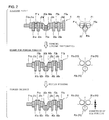
- FIG. 2 is a diagram schematically showing the shapes of a preform blank to be processed by the forming apparatus, a blank for finish forging formed therefrom, and a forged product after finish forging, in the manufacturing method of the first embodiment of the present invention.
- FIG. 2 illustrates how a three-cylinder four-counterweight crankshaft is manufactured as an example and displays plane views showing an outside appearance of the crankshaft and drawings depicting an arrangement of crank pins with a view along an axial direction side by side to facilitate understanding of the shapes of the blanks in each step.
- a preform blank 4 of the first embodiment has a crankshaft shape that is approximate to a shape of a forged crankshaft 1 for a three-cylinder four-counterweight shown in FIG. 1 (f) but is generally in a rough shape.
- the preform blank 4 includes: four rough journal portions J1a to J4a; three rough crank pin portions P1a to P3a; a rough front part portion Fra; a rough flange portion Fla; and six rough crank arm portions A1a to A6a (hereinafter also referred to simply as "rough arm portions”) that alternatively connect the rough journal portions J1a to J4a, and the rough crank pin portions P1a to P3a to each other.
- the preform blank 4 has no flash.
- a reference character "Ja” is used for the rough journal portions
- a reference character "Pa” for the rough crank pin portions
- a reference character "Aa” for the rough arm portions
- a blank for finish forging 5 of the first embodiment is formed from the preform blank 4 described above using a forming apparatus, details of which will be provided later.
- the blank for finish forging 5 includes four rough journal portions J1b to J4b, three rough crank pin portions P1b to P3b, a rough front part portion Frb, a rough flange portion Flb, and six rough crank arm portions A1b to A6b (hereinafter also referred to simply as "rough arm portions”) that alternatively connect the rough journal portions J1b to J4b, and the rough crank pin portions P1b to P3b to each other.
- the blank for finish forging 5 has no flash.
- a forged product 6 of the first embodiment is obtained from the blank for finish forging 5 described above by finish forging.
- the forged product 6 includes four journals J1c to J4c, three crank pins P1c to P3c, a front part Frc, a flange Flc, and six crank arms A1c to A6c (hereinafter also referred to simply as "arms") that alternatively connect the journals J1c to J4c, and the crank pins P1c to P3c to each other.
- the forged product 6 has a shape that is in agreement with a shape of a crankshaft (forged final product) including a placement angle of the crank pins Pc and corresponds to a forged crankshaft 1 shown in FIG. 1(f) .
- the journals Jc of the forged product 6 have an axial length equal to that of journals J of the forged crankshaft having the final shape.
- the crank pins Pc of the forged product 6 have an axial length equal to that of crank pins P of the forged crankshaft having the final shape.
- crank pins Pc of the forged product 6 have the same amount of eccentricity in a direction perpendicular to an axial direction and the same placement angle of 120° as the crank pins P of the forged crankshaft having the final shape, thus they are placed at the specified positions.
- the arms Ac of the forged product 6 have an axial thickness equal to that of arms A of the forged crankshaft having the final shape.
- the blank for finish forging 5 has a shape that is generally in agreement with the shape of the forged product 6 and corresponds exactly to a block forged blank 105 shown in FIG. 1(d) with a difference therebetween being a flash 105a.
- the rough journal portions Jb of the blank for finish forging 5 have an axial length equal to that of the journals J of the forged crankshaft having the final shape (journals Jc of forged product 6).
- the rough crank pin portions Pb of the blank for finish forging 5 have an axial length equal to that of the crank pins P of the forged crankshaft having the final shape (crank pins Pc of forged product 6).
- crank pins Pb of the blank for finish forging 5 have the same amount of eccentricity in the direction perpendicular to the axial direction and the same placement angle of 120° as the crank pins P of the forged crankshaft having the final shape, thus they are placed at the specified positions.
- the rough arm portions Ab of the blank for finish forging 5 have an axial thickness equal to that of the arms A of the forged crankshaft having the final shape (arms Ac of forged product 6).
- the rough journal portions Ja of the preform blank 4 have an axial length equal to that of the rough journal portions Jb of the blank for finish forging 5, i.e., that of the journals J of the forged crankshaft (journals Jc of forged product 6).
- the rough crank pin portions Pa of the preform blank 4 have an axial length equal to that of the rough crank pin portions Pb of the blank for finish forging 5, i.e., that of the crank pins P of the forged crankshaft (crank pins Pc of forged product 6), but have a smaller amount of eccentricity than that of the rough crank pin portions Pb of the blank for finish forging 5.
- the first and third rough crank pin portions P1a and P3a at opposite ends among the rough crank pin portions Pa of the preform blank 4 have an amount of eccentricity in the opposite direction to each other, the amount of eccentricity thereof being equal to a ⁇ 3/2 of an amount of eccentricity in the crank pins P of the forged crankshaft.
- the second rough crank pin portion P2a in the center is configured to have an amount of eccentricity in the direction perpendicular to an eccentric direction of the first and third rough crank pin portions P1a and P3a, the amount of eccentricity thereof being approximately equal to a half of an amount of eccentricity in the crank pin P of the forged crankshaft.
- the rough arm portions Aa of the preform blank 4 have an axial thickness greater than that of the rough arm portions Ab of the blank for finish forging 5, i.e., that of the arms A of the forged crankshaft (arms Ac of forged product 6).
- the preform blank 4 in comparison with the blank for finish forging 5 (forged crankshaft and forged product 6, having final shape), the preform blank 4 has an overall length that is relatively long by the additional thickness of the rough arm portions Aa, and has a smaller amount of eccentricity of the rough crank pin portions Pa.
- the preform blank 4 has a relatively gentle crankshaft shape.
- the blank for finish forging 5 has such a configuration that, with respect to the final shapes of the forged crankshaft and the forged product 6, the rough arm portions Ab are made slightly thinner and therefore the axial lengths of the rough journal portions Jb and the rough crank pin portions Pb are accordingly slightly greater.
- the preform blank 4 too, has such a configuration that, with respect to the final shapes of the forged crankshaft and the forged product 6, the axial lengths of the rough journal portions J' and the rough crank pin portions P' are accordingly slightly greater.
- FIG. 3 is a schematic diagram illustrating a process for manufacturing a forged crankshaft for a three-cylinder engine according to the first embodiment of the present invention.
- the process for manufacturing the forged crankshaft for the three-cylinder engine of the first embodiment includes a first preforming step, a second preforming step, and a finish forging step, and also includes a trimming step and a coining step as necessary.
- the first preforming step is a step in which the preform blank 4 described above is obtained.
- a preform blank 4 can be obtained by using a round billet having a circular cross section as a starting material and applying a preforming operation to the round billet after it is heated by an induction heater or a gas atmosphere furnace.
- the preform blank 4 can be obtained in a manner such that: the round billet is subjected to roll forming in which it is reduction-rolled by grooved rolls to distribute its volume in the longitudinal direction; and the resulting rolled blank is repeatedly subjected to bending in which it is partially pressed in a press from a direction perpendicular to the longitudinal direction to distribute its volume.
- the preform blank 4 may be obtained by using the techniques disclosed in Patent Literatures 1 and 2. Furthermore, cross roll forging or fully-enclosed die forging may also be employed.
- the second preforming step is a step in which the blank for finish forging 5 described above is obtained.
- the blank for finish forging 5 having the final shape of the forged crankshaft including the placement angle of crank pins can be obtained from the preform blank 4 described above by using a forming apparatus described in FIG. 4 below.
- the finish forging step is a step in which the forged product 6 described above is obtained.
- the blank for finish forging 5 is supplied to be processed by press forging with a pair of upper and lower dies, whereby the forged product 6 having a shape in agreement with the shape of the crankshaft of the forged crankshaft having the final shape including the placement angle of the crank pins can be obtained.
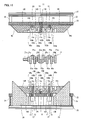
- FIG. 4 is a longitudinal sectional view showing a configuration of the forming apparatus according to the first embodiment of the present invention.
- FIG. 3 illustrates, as an example, a forming apparatus that is used in manufacturing a three-cylinder four-counterweight crankshaft, i.e., a forming apparatus configured to form the blank for finish forging 5 from the preform blank 4 shown in FIG. 2 .
- the first and third rough crank pin portions are in reality extended in a front-back direction, where either one of them is located in the front side of the paper and the other one is located in the back side of the paper, however they are illustrated on the same plane for convenience.
- the forming apparatus is configured to utilize a press machine and includes a stationary lower pressure pad 20 serving as a base and an upper pressure pad 21, which is lowered by driving a ram of the press machine.
- a lower die holder 22, located over the lower pressure pad 20, is resiliently supported via a resilient member 24.
- This lower die holder 22 is vertically movable.
- the resilient member 24 disc springs, coil springs, air springs, or the like may be employed, or a hydraulic spring system may be employed.
- An upper die holder 23 is secured under the upper pressure pad 21 via support posts 25. This upper die holder 23 is lowered together with the upper pressure pad 21 by driving the press machine (ram).
- the preform blank 4 is placed in the dies in a manner such that the first and third rough crank pin portions P1a and P3a are horizontally positioned and the second rough crank pin portion P2a is positioned in a lower side in the vertical direction, whereby the preform blank 4 is formed into the blank for finish forging.
- vertically forming pairs i.e., the journal dies 10U and 10B, the reference crank pin die 11 and the auxiliary crank pin die 13, and the movable crank pin dies 12 and the auxiliary crank pin dies 13, are apart from each other in the axial direction of the preform blank 4, and the lower and upper ones are respectively mounted on the lower die holder 22 and the upper die holder 23.
- the reference crank pin die 11 and the auxiliary crank pin die 13, vertically forming a pair, are disposed at a location of one rough crank pin portion Pa serving as a reference among the rough crank pin portions Pa of the preform blank 4, e.g., the location of the second rough crank pin portion P2a in the center in FIG. 4 , with the upper one mounted on the upper die holder 23 and the lower one mounted on the lower die holder 22.
- the reference crank pin die 11 of the first embodiment is disposed on the opposite side of a specified position of one of the rough crank pin portions Pa serving as a reference, whereas its counterpart, the auxiliary crank pin die 13 is disposed in the same side of the specified position of such rough crank pin portion Pa in the outside.
- the second rough crank pin portion P2a is positioned in the lower side, thus the specified position thereof is located in the lower side, as a result, the reference crank pin die 11 is mounted on the upper die holder 23, and its counterpart, the auxiliary crank pin die 13 is mounted on the lower die holder 22.
- the reference crank pin die 11 and the auxiliary crank pin die 13, i.e., both the upper and lower dies, are constrained from moving in the axial direction on the upper die holder 23 and the lower die holder 22, respectively. Only the reference crank pin die 11 is movable in the direction perpendicular to the axial direction, i.e., the direction toward the specified position of the rough crank pin portion Pa (downward direction in FIG. 4 ).
- the reference crank pin die 11 and the auxiliary crank pin die 13 respectively have impressions 11a and 13a having a semi-cylindrical shape.
- the length of the impressions 11a and 13a is equal to the axial length of the rough crank pin portion P2b of the blank for finish forging 5.
- the impression 11a is brought into contact with the second rough crank pin portion P2a, bringing into a state in which the reference crank pin die 11 at both side surfaces are in contact with the third and fourth rough arm portions A3a and A4a at the second rough crank pin portion P2a-side side surfaces through which the third and fourth rough arm portions A3a and A4a and the second rough crank pin portion P2a are connected.
- the movable crank pin dies 12 and the auxiliary crank pin dies 13, vertically forming pairs with each other, are disposed at locations of the corresponding rough crank pin portions Pa excluding the one with which the reference crank pin die 11 is in contact, e.g., the locations of the first and third rough crank pin portions P1a and P3a in FIG. 4 , with the upper ones mounted on the upper die holder 23 and the lower ones mounted on the lower die holder 22.
- the movable crank pin dies 12 of the first embodiment are disposed on the opposite side of specified positions of the corresponding rough crank pin portions Pa, whereas their counterparts, the auxiliary crank pin dies 13 are disposed on the same side of the specified positions of the corresponding rough crank pin portions Pa in the outside.
- the specified position of the first rough crank pin portion P1a is located in the upper side, thus the corresponding movable crank pin die 12 is mounted on the lower die holder 22, and its counterpart, the auxiliary crank pin die 13 is mounted on the upper die holder 23.
- all the movable crank pin dies 12 and the auxiliary crank pin dies 13, i.e., both the upper and lower dies, are axially movable toward the reference crank pin die 11 on the lower die holder 22 and the upper die holder 23, respectively.
- Only the movable crank pin dies 12 are movable in the direction perpendicular to the axial direction, i.e., the direction toward the specified positions of the rough crank pin portions Pa (upward direction in FIG. 4 ).
- the movable crank pin dies 12 and the auxiliary crank pin dies 13 respectively have impressions 12a and 13a having a semi-cylindrical shape.
- the length of the impressions 12a and 13a is equal to the axial length of the rough crank pin portions Pb of the blank for finish forging 5.
- the journal dies 10U and 10B are disposed at locations of the corresponding rough journal portion Ja of the preform blank 4, with the upper ones mounted on the upper die holder 23 and the lower ones mounted on the lower die holder 22.
- the journal dies 10U and 10B i.e., both the upper and lower dies, are axially movable toward the reference crank pin die 11 on the upper die holder 23 and the lower die holder 22, respectively.
- the journal dies 10U and 10B respectively have first impressions 10Ua and 10Ba having a semi-cylindrical shape and respectively have second impressions 10Ub and 10Bb, located adjacent to the first impressions 10Ua and 10Ba at the front and back (right and left as seen in FIG. 4 ).
- the length of the first impressions 10Ua and 10Ba is equal to the axial length of the rough journal portions Jb of the blank for finish forging 5.
- the length of the second impressions 10Ub and 10Bb is equal to the axial thickness of the rough arm portions Ab connecting to the rough journal portions Jb of the blank for finish forging 5.
- journal dies 10U and 10B are caused to hold and retain the rough journal portions Ja from the upper and lower sides with the first impressions 10Ua and 10Ba.
- the journal dies 10U and 10B are brought into a state in which the second impressions 10Ub and 10Bb, at their first impression 10Ua and 10Ba-side surfaces, are in contact with the rough arm portions Aa, at their rough journal portion Ja-side side surfaces through which the rough arm portions Aa and the rough journal portions Ja are connected.
- the reference crank pin die 11 and the movable crank pin dies 12 are placed in a state in which the impressions 11 a and 12a are brought into contact with the rough crank pin portions Pa, and both side surfaces of the reference crank pin die 11 and the movable crank pin dies 12 are in contact with the rough arm portions Aa at their rough crank pin portion Pa-side side surfaces through which the rough arm portions Aa and rough crank pin portions Pa are connected.
- the journal dies 10U and 10B disposed at locations of the corresponding first and fourth rough journal portions J1a and J4a at opposite ends have end surfaces, which are respectively referred to as inclined surfaces 14U and 14B.
- first wedges 26 each located correspondingly to the location of the inclined surfaces 14U and 14B of the journal dies 10U and 10B for the first and fourth rough journal portions J1a and J4a.
- Each of the first wedges 26 extends upward penetrating through the lower die holder 22.
- the inclined surfaces 14B of the lower journal dies 10B, among the journal dies 10U and 10B for the first and fourth rough journal portions J1a and J4a, are in contact with the slopes of the first wedges 26 in the initial condition.
- the inclined surfaces 14U of the upper journal dies 10U are brought into contact with the slopes of the first wedges 26 by the lowering of the upper die holder 23 caused by driving the press machine, i.e., the downward movement of the press machine.
- the journal dies 10U and 10B disposed at locations of the corresponding second and third rough journal portions J2a and J3a, which are closer to the center, are provided with blocks, not shown, secured at side sections (front and back sides of the paper in FIG. 4 ) apart from the first impressions 10Ua and 10Ba and the second impressions 10Ub and 10Bb, the blocks having inclined surfaces 15U and 15B.
- Each of the second wedges 27 extends upward penetrating through the lower die holder 22.
- the inclined surfaces 15B of the lower journal dies 10B, among the journal dies 10U and 10B for the second and third rough journal portions J2a and J3a, are in contact with the slopes of the second wedges 27 in the initial condition.
- the inclined surfaces 15U of the upper journal dies 10U are brought into contact with the slopes of the second wedges 27 by the lowering of the upper die holder 23 caused by driving the press machine, i.e., the downward movement of the press machine.
- the upper journal dies 10U are pressed downwardly together with the lower journal dies 10B.
- journal dies 10U and 10B for the second and third rough journal portions J2a and J3a are allowed to move axially toward the reference crank pin die 11 for the second rough crank pin portion P2a serving as a reference as their inclined surfaces 15U and 15B slide along the slopes of the second wedges 27.
- the journal dies 10U and 10B are all capable of being moved axially by the wedge mechanisms.
- the movable crank pin dies 12 and the auxiliary crank pin dies 13 are pressed downwardly together with continued downward movement of the press machine. Accordingly, with the axial movement of the journal dies 10U and 10B as described above, the movable crank pin dies 12 and the auxiliary crank pin dies 13 are moved axially along with them toward the reference crank pin die 11 for the second rough crank pin portion P2a serving as a reference. The movement of the reference crank pin die 11 and the movable crank pin die 12 in the direction perpendicular to the axial direction is accomplished by driving the hydraulic cylinders 16 coupled to the crank pin dies 11 and 12.
- axial movement of the movable crank pin dies 12 and the auxiliary crank pin dies 13 may be forcibly caused using a wedge mechanism similar to the one for the journal dies 10U and 10B or a separate mechanism such as a hydraulic cylinder or a servo motor.
- the auxiliary crank pin dies 13 may be integral with one of their adjacent journal dies 10U and 10B forming pairs.
- FIG. 5 and FIG. 6 are longitudinal sectional views illustrating a process for forming a blank for finish forging using the forming apparatus of the first embodiment of the present invention shown in FIG. 4 , with FIG. 5 showing a forming state at the initial stage and FIG. 6 showing a forming state at the completion.
- the preform blank 4 is placed in the lower journal die 10B, the movable crank pin dies 12, and the auxiliary crank pin dies 13, shown in FIG. 4 , and then lowering of the press machine is started. Then, as shown in FIG. 5 , the upper journal dies 10U are brought into contact with the corresponding lower journal dies 10B.
- the preform blank 4 is brought into a state in which the rough journal portions Ja are held by the journal dies 10U and 10B from above and below, and the rough crank pin portions Pa are contacted by the reference crank pin die 11 and the movable crank pin dies 12.
- the rough arm portions Aa, at their rough journal portion Ja-side side surfaces are in contact with the journal dies 10U and 10B, and the rough arm portions Aa, at their rough crank pin portion Pa-side side surfaces, are in contact with the reference crank pin die 11 and the movable crank pin dies 12.
- the inclined surfaces 14U and 14B of the journal dies 10U and 10B for the first and fourth rough journal portions J1a and J4a are in contact with the slopes of the first wedges 26 and the inclined surfaces 15U and 15B of the journal dies 10U and 10B for the second and third rough journal portions J2a and J3a are in contact with the slopes of the second wedges 27.
- journal dies 10U and 10B for the first and fourth rough journal portions J1a and J4a slide along the slopes of the first wedges 26, and by this wedge mechanism, these journal dies 10U and 10B are allowed to move axially toward the reference crank pin die 11 for the second rough crank pin portion P2a.
- the inclined surfaces 15U and 15B of the journal dies 10U and 10B for the second and third rough journal portions J2a and J3a slide along the slopes of the second wedges 27, and by this wedge mechanism, these journal dies 10U and 10B are also allowed to move axially toward the reference crank pin die 11 for the second rough crank pin portion P2a.
- the movable crank pin dies 12 and the auxiliary crank pin dies 13 are also allowed to move axially toward the reference crank pin die 11.
- the spaces between the journal dies 10U and 10B, the reference crank pin die 11, the movable crank pin dies 12, and the auxiliary crank pin dies 13 are gradually narrowed, and finally filled.
- the rough arm portions Aa are axially compressed by the journal dies 10U and 10B, the reference crank pin die 11, and the movable crank pin dies 12, while the axial lengths of the rough journal portions Ja and the rough crank pin portions Pa are maintained, so that the thickness of the rough arm portions Aa is reduced to the thickness of the rough arm portions Ab of the blank for finish forging 5 (see FIG. 6 ).
- each of the hydraulic cylinders 16 for the reference crank pin die 11 and the movable crank pin dies 12 is operated. Accordingly, the crank pin dies 11 and 12 press the corresponding rough crank pin portions Pa of the preform blank 4 in the direction perpendicular to the axial direction.
- the rough crank pin portions Pa of the preform blank 4 are displaced in the vertical direction perpendicular to the axial direction, and an amount of eccentricity thereof is increased to an amount of eccentricity of the rough crank pin portions Pb of the blank for finish forging 5, bringing into a state in which all the rough crank pin portions Pb are disposed in their specified positions (see FIGS. 2 and 6 ).
- the blank for finish forging 5 without a flash which has a shape generally in agreement with the shape of the forged crankshaft for the three-cylinder engine having thin arms A (forged final product).
- the blank for finish forging 5 without a flash for finish forging By supplying such a blank for finish forging 5 without a flash for finish forging, and performing finish forging with it, it is possible to obtain the final shape of the forged crankshaft for the three-cylinder engine including the contour shape of arms and the placement angle of the crank pins, although some minor amount of flash is generated. Therefore, forged crankshafts for three-cylinder engines can be manufactured with high material utilization and also with high dimensional accuracy regardless of their shapes. If, at the stage of preparing the preform blank, the arm portions are shaped so as to include portions for forming balance weights, it is even possible to manufacture forged crankshafts having balance weights.
- the inclined surfaces 14U and 14B of the journal dies 10U and 10B for the first rough journal portion J1a and its contacting slope of the first wedge 26, and the inclined surfaces 14U and 14B of the journal dies 10U and 10B for the fourth rough journal portion J4a and its contacting slope of the first wedge 26 are angled in a reverse relationship relative to a vertical plane.
- the inclined surfaces 15U and 15B of the journal dies 10U and 10B for the second rough journal portion J2a and its contacting slope of the second wedge 27, and the inclined surfaces 15U and 15B of the journal dies 10U and 10B for the third rough journal portion J3a and its contacting slope of the second wedge 27 are angled in a reverse relationship relative to a vertical plane.
- the angle of the slopes of the first wedges 26 (the angle of the inclined surfaces 14U and 14B of the journal dies 10U and 10B for the first and fourth rough journal portions J1a and J4a) is greater than the angle of the slopes of the second wedges 27 (the angle of the inclined surfaces 15U and 15B of the journal dies 10U and 10B for the second and third rough journal portions J2a and J3a).
- the purpose of varying, for each of the journal dies 10U and 10B, the wedge angle of the wedge mechanism, which causes the axial movement of the journal dies 10U and 10B, is to ensure that the rate of deformation at which the rough arm portions Aa are axially compressed to reduce the thickness thereof stays constant for all the rough arm portions Aa.
- the rough journal portions Ja have a cross-sectional area that is equal to or greater than that of the rough journal portions Jb of the blank for finish forging 5, i.e., that of the journals J of the forged crankshaft.
- the rough crank pin portions Pa of the preform blank 4 have a cross-sectional area that is equal to or greater than that of the rough crank pin portions Pb of the blank for finish forging 5, i.e., that of the crank pins P of the forged crankshaft.
- the cross-sectional area of the rough journal portions Ja of the preform blank 4 is greater than the cross-sectional area of the rough journal portions Jb of the blank for finish forging 5, and the cross-sectional area of the rough crank pin portions Pa of the preform blank 4 is greater than the cross-sectional area of the rough crank pin portions Pb of the blank for finish forging 5: the cross-sectional area of the rough journal portions Ja can be reduced to the cross-sectional area of the rough journal portions Jb of the blank for finish forging 5 by the holding and retaining of the rough journal portions Ja by the journal dies 10U and 10B, and by the subsequent axial movement of the journal dies 10U and 10B; and the cross-sectional area of the rough crank pin portions Pa can be reduced to the cross-sectional area of the rough crank pin portions Pb of the blank for finish forging 5 by the movement in the direction perpendicular to the axial direction of the reference crank pin die 11, and also by the axial movement and the movement in the direction perpendicular to the axial direction of the axial
- FIG. 7 is a diagram illustrating how fin flaws occur in forming a blank for finish forging using the forming apparatus of the present invention
- FIG. 8 is a diagram illustrating how fin flaws are prevented by taking a measure.
- FIGS. 7 and 8 there are shown (a) a forming state at an initial stage, (b) a forming state during the process, (c) a forming state at the completion, and (d) a blank for finish forging, which is removed from the forming apparatus after the completion of forming.
- the fin flaws 5a will be struck into the finished product, resulting in causing overlaps. Therefore, in order to ensure product quality, it is necessary to prevent the formation of the fin flaws.
- One measure to prevent the formation of the fin flaws may be to control the movement of the reference crank pin die 11 and the movable crank pin dies 12 in the direction perpendicular to the axial direction so that the rough crank pin portions Pa to be processed for deformation by pressing reach the auxiliary crank pin dies 13 after the spaces between the journal dies 10U and 10B, the reference crank pin die 11, the movable crank pin dies 12, and the auxiliary crank pin dies 13, are filled.
- journal dies 10U and 10B as well as that of the movable crank pin dies 12 and the auxiliary crank pin dies 13 forming pair with the movable crank pin dies 12 is completed, thereafter the movement of the reference crank pin die 11 and the movable crank pin dies 12 in the direction perpendicular to the axial direction is completed.
- the length of movement of the crank pin dies 11 and 12 in the direction perpendicular to the axial direction is designated as a 100% length of movement thereof, it is preferred that, when the axial movement of the journal dies 10U and 10B that are adjacent to the crank pin dies 11 and 12 is completed, the length of movement of the crank pin dies 11 and 12 in the direction perpendicular to the axial direction is 90% or less (more preferably 83% or less, and even more preferably 60% or less) of the total length of movement, and thereafter, the movement of the crank pin dies 11 and 12 in the same direction is completed.
- the forming operation is started as shown in FIG. 8(a) , and then, as shown in FIG. 8(b) , the axial movement of the journal dies 10U and 10B as well as that of the movable crank pin dies 12 and the auxiliary crank pin dies 13 are completed before the length of movement of the reference crank pin die 11 and the movable crank pin dies 12 in the direction perpendicular to the axial direction reaches 90% of the total length of movement. Consequently, by this time, the spaces between the journal dies 10U and 10B, the reference crank pin die 11, the movable crank pin dies 12, and the auxiliary crank pin dies 13 have been filled, whereas the rough crank pin portions Pa to be processed for deformation by pressing have not reached the auxiliary crank pin dies 13.
- the process of movement of the crank pin dies in the direction perpendicular to the axial direction before the completion of the axial movement of the journal dies may be varied as desired.
- the movement of the crank pin dies in the direction perpendicular to the axial direction may be started simultaneously with the start of the axial movement of the journal dies or in advance of that, or conversely, it may be started after the axial movement of the journal dies has progressed to some extent.
- the movement of the crank pin dies in the direction perpendicular to the axial direction may be stopped temporarily after its start, at positions a certain distance away from their initial positions, and it may be resumed after the completion of the axial movement of the journal dies.
- a second embodiment is based on the configuration of the first embodiment described above and includes a twisting step in a process of manufacturing a forged crankshaft for a three-cylinder engine as well as modifications of the configuration related to this step.
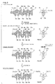
- FIG. 9 is a diagram schematically showing the shapes of a preform blank to be processed by the forming apparatus, a blank for finish forging formed therefrom, a forged product after finish forging, and a twisted product after twisting, in the manufacturing method of the second embodiment of the present invention.
- FIG. 9 illustrates how a three-cylinder six-counterweight crankshaft is manufactured as an example and displays, as seen in FIG. 2 , plane views showing an outside appearance of the crankshaft and drawings depicting an arrangement of crank pins with a view along an axial direction side by side. It is noted that the descriptions of the matters that overlap with the first embodiment shall be appropriately omitted. This is also the case for third and fourth embodiments described later.
- a preform blank 4 of the second embodiment has a crankshaft shape that is approximate to the shape of a forged crankshaft 1 for a three-cylinder six-counterweight, but is generally in rough shape.
- the preform blank 4 includes four rough journal portions Ja, three rough crank pin portions Pa, a rough front part portion Fra, a rough flange portion Fla, and six rough arm portions Aa.
- a blank for finish forging 5 of the second embodiment is formed from the preform blank 4 described above using a forming apparatus, details of which will be provided later.
- the blank for finish forging 5 includes four rough journal portions Jb, three rough crank pin portions Pb, a rough front part portion Frb, a rough flange portion Flb, and six rough arm portions Ab.
- a forged product 6 of the second embodiment is obtained from the blank for finish forging 5 described above by finish forging.
- the forged product 6 includes four journals Jc, three crank pins Pc, a front part Frc, a flange Flc, and six arms Ac.
- a twisted product 7 of the second embodiment is obtained from the forged product 6 described above by twisting.
- the twisted product 7 includes four journals J1d to J4d, three crank pins P1d to P3d, a front part Frd, a flange Fld, and six crank arms A1d to A6d (hereinafter also referred to simply as “arms”) that alternatively connect the journals J1d to J4d, and the crank pins P1d to P3d to each other.
- the twisted product 7 has a shape that is in agreement with a shape of a crankshaft (forged final product) including a placement angle of the crank pins Pd.
- the journals Jd of the twisted product 7 have an axial length equal to that of the journals J of the forged crankshaft having the final shape.
- the crank pins Pd of twisted product 7 have an axial length equal to that of the crank pins P of the forged crankshaft having the final shape.
- the crank pins Pd of the twisted product 7 have the same amount of eccentricity in the direction perpendicular to the axial direction and the same placement angle of 120° as the crank pins P of the forged crankshaft having the final shape, thus they are placed at the specified positions.
- the arms Ad of the twisted product 7 have an axial thickness equal to that of arms A of the forged crankshaft having the final shape.
- the forged product 6 has a shape that is in agreement with the shape of the crankshaft (forged final product) excluding the placement angle of the crank pins Pc.
- the journals Jc of the forged product 6 have an axial length equal to that of the journals J of the forged crankshaft having the final shape.
- the crank pins Pc of the forged product 6 have an axial length equal to that of the crank pins P of the forged crankshaft having the final shape, and an amount of eccentricity in the direction perpendicular to the axial direction is the same between them.
- the placement angle of the crank pins Pc of the forged product 6 is deviated from specified positions.
- the first and third crank pins P1c and P3c at opposite ends are eccentric in the direction perpendicular to the axial direction in the same direction, whereas the second crank pins P2c in the center is eccentric in the direction opposite to an eccentric direction of the first and third crank pins P1c and P3c.
- the arms Ac of the forged product 6 have an axial thickness equal to that of arms A of the forged crankshaft having the final shape.
- the blank for finish forging 5 has a shape that is generally in agreement with the shape of the forged product 6.
- the rough journal portions Jb of the blank for finish forging 5 have an axial length equal to that of the journals J of the forged crankshaft having the final shape (journals Jc of forged product 6).
- the rough crank pin portions Pb of the blank for finish forging 5 have an axial length equal to that of the crank pins P of the forged crankshaft having the final shape (crank pins Pc of forged product 6), and the amount of eccentricity in the direction perpendicular to the axial direction is the same between them.
- the placement angle of the blank for finish forging 5 is, like the forged product 6, deviated from the specified positions.
- the rough arm portions Ab of the blank for finish forging 5 have an axial thickness equal to that of the arms A of the forged crankshaft having the final shape (arms Ac of forged product 6).
- the rough journal portions Ja of the preform blank 4 have an axial length equal to that of the rough journal portions Jb of the blank for finish forging 5, i.e., that of the journals J of the forged crankshaft (journals Jc of forged product 6).
- the rough crank pin portions Pa of the preform blank 4 have an axial length equal to that of the rough crank pin portions Pb of the blank for finish forging 5, i.e., that of the crank pins P of the forged crankshaft (crank pins Pc of forged product 6), but have a smaller amount of eccentricity than that of the rough crank pin portions Pb of the blank for finish forging 5.
- the first and third rough crank pin portions P1a and P3a at opposite ends are eccentric in the same direction with an amount of eccentricity thereof equal to about a half of an amount of eccentricity in the crank pins P of the forged crankshaft.
- the second rough crank pin portion P2a in the center is eccentric in a direction opposite to an eccentric direction of the first and third rough crank pin portions P1a and P3a with an amount of eccentricity equal to about a half of an amount of eccentricity in the crank pin P of the forged crankshaft.
- the rough arm portions Aa of the preform blank 4 have an axial thickness greater than that of the rough arm portions Ab of the blank for finish forging 5, i.e., that of the arms A of the forged crankshaft (arms Ac of forged product 6).
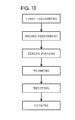
- FIG. 10 is a schematic diagram illustrating a process for manufacturing a forged crankshaft for a three-cylinder engine according to the second embodiment of the present invention.
- the process for manufacturing the forged crankshaft for the three-cylinder engine of the second embodiment includes a first preforming step, a second preforming step, a finish forging step, and a twisting step, and also includes a trimming step before the twisting step and a coining step after the twisting step as necessary.
- the first preforming step is a step in which the preform blank 4 described above is obtained.
- the second preforming step is a step in which the blank for finish forging 5 described above having the final shape of the forged crankshaft excluding the placement angle of crank pins is obtained from the preform blank 4 described above by using a forming apparatus described in FIG. 11 below.
- the finish forging step is a step in which the blank for finish forging 5 is supplied to be processed by finish forging, whereby the forged product 6 described above having the final shape of the forged crankshaft excluding the placement angle of crank pins is obtained.
- the twisting step is a step in which the twisted product 7 described above is obtained.
- the journals and the crank pins of the forged product 6 described above are held and retained, the journals are twisted around these axial centers in order to adjust the placement angle of the crank pins of the forged product 6 to the placement angle of the crank pins of the forged crankshaft, so that the twisted product 7 having a final shape that is in agreement with the shape of the crankshaft of the forged crankshaft including the placement angle can be obtained.
- FIG. 11 is a longitudinal sectional view showing a configuration of the forming apparatus according to the second embodiment of the present invention.
- FIG. 11 illustrates, as an example, the forming apparatus that is used in manufacturing a three-cylinder six-counterweight crankshaft, i.e., the forming apparatus configured to form the blank for finish forging 5 from the preform blank 4 shown in FIG. 9 . It should be noted that in the longitudinal sectional view shown in FIG. 11 , all parts of the rough crank pin portions are actually on the same plane.
- the preform blank 4 is placed in the dies in a manner such that an eccentric direction of the rough crank pin portions Pa is in the vertical direction, e.g., with the first and third rough crank pin portions P1a and P3a positioned in the upper side and the second rough crank pin portion P2a positioned in the lower side, so that the preform blank 4 is formed into the blank for finish forging 5.
- the same configuration is shared with the forming apparatus of the first embodiment shown in FIG. 4 , thus the detailed description thereof will be omitted.
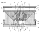
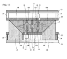
- FIGS. 12 and 13 are longitudinal sectional views illustrating a process for forming the blank for finish forging using the forming apparatus according to the second embodiment of the present invention shown in FIG. 11 .
- FIGS. 12 and 13 respectively show a forming state at an initial stage and a forming state at the completion.
- the preform blank 4 is placed in the lower journal die 10B, the movable crank pin dies 12, and the auxiliary crank pin dies 13, and then lowering of the press machine is performed.
- This allows the journal dies 10U and 10B holding and retaining the rough journal portions Ja to move axially toward the reference crank pin die 11 in contact with the second rough crank pin portion P2a.
- the movable crank pin dies 12 and the auxiliary crank pin dies 13 in contact with the first and third rough crank pin portions P1a and P3a are moved axially toward the reference crank pin die 11.
- the rough arm portions Aa are axially compressed by the journal dies 10U and 10B, the reference crank pin die 11, and the movable crank pin dies 12, while the axial length of the rough journal portions Ja and the rough crank pin portions Pa is maintained, so that the thickness of the rough arm portions Aa is reduced to the thickness of the rough arm portions Ab of the blank for finish forging 5 (see FIG. 13 ).
- the reference crank pin dies 11 and the movable crank pin dies 12 press the rough crank pin portions Pa of the preform blank 4 in the direction perpendicular to the axial direction by the operation of each hydraulic cylinders 16.
- the rough crank pin portions Pa of the preform blank 4 are displaced in the direction perpendicular to the axial direction, thus despite that the placement angle of the rough crank pin portions Pa is deviated from the specified positions, the amount of eccentricity thereof is increased to the amount of eccentricity of the rough crank pin portions Pb of the blank for finish forging 5 (see FIGS. 9 and 13 ).
- the blank for finish forging 5 without a flash which has a shape generally in agreement with the shape of the forged crankshaft for the three-cylinder engine having thin arms A (forged final product) excluding the placement angle of the crank pins P.
- the forged product 6 having the final shape of the forged crankshaft for the three-cylinder engine including the contour shape of arms but excluding the placement angle of the crank pins, although some minor amount of flash is generated.
- forged crankshafts for three-cylinder engines can be manufactured with high material utilization and also with high dimensional accuracy regardless of their shapes.
- a third embodiment is based on the configuration of the first and second embodiments described above, but includes modifications in the relevant parts of the configuration, so that a final shape of a forged crankshaft can be formed as desired in finish forging step without applying the twisting step in a process of manufacturing the forged crankshaft for a three-cylinder engine.
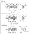
- FIG. 14 is a diagram schematically showing the shapes of a preform blank to be processed by the forming apparatus, a blank for finish forging formed therefrom, and a forged product after finish forging, in the manufacturing method of the third embodiment of the present invention.
- FIG. 14 illustrates how a three-cylinder four-counterweight crankshaft is manufactured as an example.
- the preform blank 4 of the third embodiment has a crankshaft shape that is approximate to the shape of a forged crankshaft 1 for the three-cylinder four-counterweight, but is generally in a rough shape.
- the preform blank 4 includes four rough journal portions Ja, three rough crank pin portions Pa, a rough front part portion Fra, a rough flange portion Fla, and six rough arm portions Aa.
- the blank for finish forging 5 of the third embodiment is formed from the preform blank 4 described above using a forming apparatus, details of which will be provided below.
- the blank for finish forging 5 includes four rough journal portions Jb, three rough crank pin portions Pb, a rough front part portion Frb, a rough flange portion Flb, and six rough arm portions Ab.
- the forged product 6 of the third embodiment is obtained from the blank for finish forging 5 described above by finish forging and includes four journals Jc, three crank pins Pc, a front part Frc, a flange Flc, and six arms Ac.
- the forged product 6 has a shape that is in agreement with the shape of the crankshaft (forged final product) including a placement angle of the crank pins Pc.
- the journals Jc of the forged product 6 have an axial length equal to that of the journals J of the forged crankshaft having the final shape.
- the crank pins Pc of the forged product 6 have an axial length equal to that of the crank pins P of the forged crankshaft having the final shape.
- the crank pins Pc of the forged product 6 have the same amount of eccentricity in a direction perpendicular to an axial direction and the same placement angle of 120° as the crank pins P of the forged crankshaft having the final shape, thus they are placed at the specified positions.
- the arms Ac of the forged product 6 have an axial thickness equal to that of arms A of the forged crankshaft having the final shape.
- the rough journal portions Jb of the blank for finish forging 5 have an axial length equal to that of the journals Jc of forged product 6, i.e., that of the journals J of the forged crankshaft.
- the rough crank pin portions Pb of the blank for finish forging 5 have an axial length equal to that of the crank pins Pc of forged product 6, i.e., that of the crank pins P of the forged crankshaft, but both the amount of eccentricity and the placement angle of the rough crank pin portions Pb are deviated from the specified positions.
- the first and third rough crank pin portions P1b and P3b at opposite ends are eccentric in the opposite direction to each other with an amount of eccentricity equal to a ⁇ 3/2 of an amount of eccentricity in the crank pins P of the forged crankshaft.
- the second rough crank pin portion P2b is not eccentric and has an amount of eccentricity of zero.
- the rough arm portions Ab of the blank for finish forging 5 have an axial thickness equal to that of the arms A of the forged crankshaft having the final shape (arms Ac of forged product 6).
- the rough journal portions Ja of the preform blank 4 have an axial length equal to that of the rough journal portions Jb of the blank for finish forging 5, i.e., that of the journals J of the forged crankshaft (journals Jc of forged product 6).
- the rough crank pin portions Pa of the preform blank 4 have an axial length equal to that of the rough crank pin portions Pb of the blank for finish forging 5, i.e., that of the crank pins P of the forged crankshaft (crank pins Pc of forged product 6).
- the first and third rough crank pin portions P1a and P3a have a smaller amount of eccentricity than that of the rough crank pin portions Pb of the blank for finish forging 5, and are eccentric in the opposite direction to each other with an amount of eccentricity less than the ⁇ 3/2 of the amount of eccentricity in the crank pins P of the forged crankshaft.
- the second rough crank pin portion P2a has a amount of eccentricity of zero, similar to the second rough crank pin portion P2b in the blank for finish forging 5.
- the rough arm portions Aa of the preform blank 4 have an axial thickness greater than that of the rough arm portions Ab of the blank for finish forging 5, i.e., that of the arms A of the forged crankshaft (crank arms Ac of forged product 6).
- FIG. 15 is a schematic diagram illustrating a process for manufacturing the forged crankshaft for the three-cylinder engine according to the third embodiment of the present invention.
- the process for manufacturing the forged crankshaft for the three-cylinder engine of the third embodiment includes a first preforming step, a second preforming step, and a finish forging step, and also includes a trimming step and a coining step as necessary.
- the first preforming step is a step in which the preform blank 4 described above is obtained.
- the second preforming step is a step in which the blank for finish forging 5 described above having the final shape of the forged crankshaft is obtained from the preform blank 4 described above excluding the amount of eccentricity and the placement angle of all the crank pins, by using a forming apparatus described in FIG. 16 below.
- the finish forging step is a step in which the forged product 6 described above is obtained.
- the blank for finish forging 5 described above is supplied to be processed by press forging with a pair of upper and lower dies in a state in which the first and third rough crank pin portions are horizontally positioned, whereby all rough crank pin portions are pressed in the vertical direction perpendicular to the axial direction.
- the forged product 6 having a shape in agreement with the shape of the crankshaft of the forged crankshaft having the final shape can be obtained including the placement angle of the crank pins.
- FIG. 16 is a longitudinal sectional view showing a configuration of the forming apparatus according to the third embodiment of the present invention.
- FIG. 16 illustrates, as an example, the forming apparatus that is used in forming the blank for finish forging 5 from the preform blank 4 shown in FIG. 14 . It should be noted that in the longitudinal sectional view shown in FIG. 16 , all parts of the rough crank pin portions are actually on the same plane.
- the forming apparatus of the third embodiment shown in FIG. 16 differs from the forming apparatus of the first embodiment shown in FIG. 4 and the forming apparatus of the second embodiment shown in FIG. 11 largely in the following.
- the preform blank 4 is placed in the dies in a manner such that the first and third rough crank pin portions P1a and P3a which are eccentric in the opposite direction to each other are vertically positioned, whereby the preform blank 4 is formed into the blank for finish forging 5.
- the reference crank pin die 11 disposed in the location of the second rough crank pin portion P2a is constrained from moving not only in the axial direction but also in the direction perpendicular to the axial direction.
- the reference crank pin die 11 of the third embodiment is, unlike the one in the first and second embodiments, not coupled to a hydraulic cylinder, instead, directly mounted to one of the upper die holder 23 and the lower die holder 22.
- the auxiliary crank pin die 13 forming a pair with the reference crank pin die 11 is directly mounted.
- FIG. 16 shows a mode in which the reference crank pin die 11 is mounted to the upper die holder 23 while the auxiliary crank pin die 13 is mounted to the lower die holder 22.
- the movable crank pin dies 12 and the auxiliary crank pin dies 13 are disposed at locations of the rough crank pin portions P1a and P3a.
- the first and third rough crank pin portions P1a and P3a are eccentric in the opposite direction to each other in the vertical direction, a vertical arrangement of the movable crank pin dies 12 and the auxiliary crank pin dies 13 is reversed between the locations of the first and third rough crank pin portions P1a and P3a.
- FIG 16 shows a mode in which the auxiliary crank pin die 13 at the location of the first rough crank pin portion P1a and the movable crank pin die 12 at the location of the third rough crank pin portion P3a are disposed on the upper side while the movable crank pin die 12 at the location of the first rough crank pin portion P1a and the auxiliary crank pin die 13 at the location of the third rough crank pin portion P3a are disposed on the lower side.
- FIGS. 17 and 18 are longitudinal sectional views illustrating a process for forming a blank for finish forging using the forming apparatus according to the third embodiment of the present invention shown in FIG. 16 .
- FIGS. 17 and 18 respectively show a forming state at an initial stage and at the completion.
- the preform blank 4 is placed in the lower journal die 10B, the movable crank pin dies 12, and the auxiliary crank pin dies 13, and then lowering of the press machine is performed. Then, the journal dies 10U and 10B are caused to hold and retain the rough journal portions Ja of the preform blank 4 therebetween from above and below, and concurrently, the reference crank pin die 11 and the auxiliary crank pin die 13 are caused to hold and retain the second rough crank pin portion P2a therebetween from above and below, bringing into a state in which the first and third rough crank pin portions P1a and P3a are in contact with the movable crank pin dies 12. In this state, the lowering of the press machine is continued.
- journal dies 10U and 10B holding and retaining each rough journal portion Ja to move axially toward the reference crank pin die 11 holding and retaining the second rough crank pin portion P2a.
- the movable crank pin dies 12 and the auxiliary crank pin dies 13 in contact with the first and third rough crank pin portions P1a and P3a are moved axially toward the reference crank pin die 11.
- the rough arm portions Aa are axially compressed by the journal dies 10U and 10B, the reference crank pin die 11, and the movable crank pin dies 12, while the axial length of the rough journal portions Ja and the rough crank pin portions Pa is maintained, so that the thickness of the rough arm portions Aa is reduced to the thickness of the rough arm portions Ab of the blank for finish forging 5 (see FIG. 18 ).
- the movable crank pin dies 12 press the first and third rough crank pin portions P1a and P3a of the preform blank 4 in the vertical direction perpendicular to the axial direction by the operation of each hydraulic cylinders 16.
- the first and third rough crank pin portions P1a and P3a of the preform blank 4 are displaced in the vertical direction perpendicular to the axial direction, thus the amount of eccentricity thereof in the opposite direction to each other is increased to an amount of eccentricity equal to a ⁇ 3/2 of an amount of eccentricity in the crank pins P of the forged crankshaft (see FIGS. 14 and 18 ).
- the location of the second rough crank pin portion P2b of the preform blank 4 in the vertical direction perpendicular to the axial direction remains unchanged before and after the forming, thus the amount of eccentricity thereof remains zero.
- Such a blank for finish forging 5 without a flash is supplied for finish forging, and finish forging is performed with it in a state in which the first and third rough crank pin portions P1a and P3a are horizontally positioned.
- finish forging 5 by pressing all the rough crank pin portions of the blank for finish forging 5 in the vertical direction perpendicular to the axial direction so as to displace them to the specified positions, it is possible to obtain the final shape of the forged crankshaft for the three-cylinder engine including the contour shape of arms, and the amount of eccentricity and the placement angle of the crank pins, although some minor amount of flash is generated. Therefore, forged crankshafts for three-cylinder engines can be manufactured with high material utilization and also with high dimensional accuracy regardless of their shapes.
- a fourth embodiment includes modifications of the configuration of the third embodiment.
- FIG. 19 is a diagram schematically showing the shapes of a preform blank to be processed by the forming apparatus, a blank for finish forging formed therefrom, and a forged product after finish forging, in the manufacturing method of the fourth embodiment of the present invention.
- the forged product 6 of the fourth embodiment maintains the same shape as the forged product 6 of the third embodiment shown in FIG. 14 .
- the blank for finish forging 5 of the fourth embodiment differs from the blank for finish forging 5 of the third embodiment shown in FIG. 14 in the following.
- central second rough crank pin portion P2b of the blank for finish forging 5 of the fourth embodiment is configured to be eccentric in a direction perpendicular to an eccentric direction of the first and third rough crank pin portions P1b and P3b at opposite ends with an amount of eccentricity equal to that of the crank pin Pc of the forged product 6, i.e., that of the crank pin P of the forged crankshaft.
- the preform blank 4 of the fourth embodiment differs from the preform blank 4 of the third embodiment shown in FIG. 14 in the following.
- central second rough crank pin portion P2b of the preform blank 4 of the fourth embodiment is configured to be eccentric in a direction perpendicular to an eccentric direction of first and third rough crank pin portions P1b and P3b at opposite ends with an amount of eccentricity equal to that of the crank pin P of the forged crankshaft (crank pin Pc of forged product 6), the configuration similar to that of the blank for finish forging 5.
- FIG. 20 is a schematic diagram illustrating a process for manufacturing a forged crankshaft for a three-cylinder engine according to the fourth embodiment of the present invention.
- the process for manufacturing the forged crankshaft of the fourth embodiment similar to the third embodiment shown in FIG. 15 , includes a first preforming step, a second preforming step, and a the finish forging step, and also includes a trimming step and a coining step as necessary.
- the first preforming step is a step in which the preform blank 4 described above is obtained.
- the second preforming step is a step in which the blank for finish forging 5 described above is obtained.
- the same forming apparatus used in the third embodiment shown in FIGS. 16-18 is used. It should be noted that in the longitudinal sectional view shown in FIG. 16 , the second rough crank pin portion in the fourth embodiment is in reality located either in the front or back side of the paper.
- the preform blank 4 is placed in the lower journal die 10B, the movable crank pin dies 12, and the auxiliary crank pin dies 13, and then lowering of the press machine is performed.
- this allows the journal dies 10U and 10B holding and retaining each rough journal portion Ja, and the movable crank pin dies 12 and the auxiliary crank pin dies 13 in contact with the first and third rough crank pin portions P1a and P3a to move axially toward the reference crank pin die 11 holding and retaining the second rough crank pin portion P2a.
- the rough arm portions Aa are axially compressed while the axial length of the rough journal portions Ja and the rough crank pin portions Pa is maintained, so that the thickness of the rough arm portions Aa is reduced to the thickness of the rough arm portions Ab of the blank for finish forging 5.
- first and third rough crank pin portions P1a and P3a are pressed by the movable crank pin dies 12 in the vertical direction perpendicular to the axial direction, so that the first and third rough crank pin portions P1a and P3a of the preform blank 4 become eccentric in the opposite direction to each other with an amount of eccentricity increased to a ⁇ 3/2 of an amount of eccentricity in the crank pins P of the forged crankshaft.
- the location of the second rough crank pin portion P2b of the preform blank 4 in the direction perpendicular to the axial direction remains unchanged before and after the forming, thus an amount of eccentricity thereof remains the same as that of the crank pin P of the forged crankshaft.
- the blank for finish forging 5 without a flash which has a shape generally in agreement with the shape of the forged crankshaft for the three-cylinder engine having thin arms A (forged final product) excluding the amount of eccentricity and the placement angle of the first and third crank pins P1 and P3.
- the finish forging step is a step in which the forged product 6 described above is obtained.
- the blank for finish forging 5 is supplied to be processed for finish forging in a state that in which the first and third rough crank pin portions are horizontally positioned.
- this process by pressing the first and third rough crank pin portions P1b and P3b of the blank for finish forging 5 in the vertical direction perpendicular to the axial direction so as to displace them to the specified positions, it is possible to obtain the forged product 6 having a shape in agreement with the shape of the crankshaft of the forged crankshaft for the three-cylinder engine having the final shape including the contour shape of arms, and the amount of eccentricity and the placement angle of the crank pins, although some minor amount of flash is generated.
- the mechanism for causing the journal dies to move axially is not limited to the one described in the above embodiments, in which a wedge mechanism of a press machine is employed.
- a link mechanism may be employed, or a hydraulic cylinder or a servo motor may be employed in place of the press machine.
- the mechanism for causing the crank pin dies to move in the direction perpendicular to the axial direction is not limited to a hydraulic cylinder, and it may be a servo motor.
- the embodiments described above have such a configuration that the upper die holder is secured to the upper pressure pad while the lower die holder is resiliently supported on the lower pressure pad on which the wedges are installed, and the upper and lower journal dies are allowed to move by the wedges, but alternatively, the functions of the upper section and the lower section may be reversed.
- the configuration may also be such that the upper and lower die holders are resiliently supported on the corresponding pressure pads, and that wedges are installed on both pressure pads so that the upper and lower journal dies are caused to move by their corresponding wedges.
- the auxiliary crank pin dies are movable only axially, but additionally, they may be made to be movable also in a direction toward the crank pin dies forming pairs, so that the crank pin dies and the auxiliary crank pin dies can hold and retain the rough crank pin portions Pa therebetween from above and below and meanwhile move in the direction perpendicular to the axial direction cooperatively with each other.
- the embodiments described above have such a configuration that the rough crank pin portions Pa are pressed in the vertical direction by moving the crank pin dies in the direction perpendicular to the axial direction, however the configuration may also be such that the locations of the crank pin dies and the journal dies are changed so as to horizontally press the rough crank pin portions Pa.
- the present invention is useful in manufacturing forged crankshafts for three-cylinder engines.
Landscapes
- Engineering & Computer Science (AREA)
- Mechanical Engineering (AREA)
- General Engineering & Computer Science (AREA)
- Ocean & Marine Engineering (AREA)
- Forging (AREA)
- Shafts, Cranks, Connecting Bars, And Related Bearings (AREA)
Applications Claiming Priority (2)
| Application Number | Priority Date | Filing Date | Title |
|---|---|---|---|
| JP2012271202 | 2012-12-12 | ||
| PCT/JP2013/007188 WO2014091730A1 (fr) | 2012-12-12 | 2013-12-06 | Dispositif pour former un élément de forgeage de finition pour un vilebrequin forgé de moteur à 3 cylindres et procédé de production d'un vilebrequin forgé de moteur à 3 cylindres qui utilise ce dispositif |
Publications (3)
| Publication Number | Publication Date |
|---|---|
| EP2933038A1 true EP2933038A1 (fr) | 2015-10-21 |
| EP2933038A4 EP2933038A4 (fr) | 2016-08-17 |
| EP2933038B1 EP2933038B1 (fr) | 2020-01-22 |
Family
ID=50934038
Family Applications (1)
| Application Number | Title | Priority Date | Filing Date |
|---|---|---|---|
| EP13862380.6A Active EP2933038B1 (fr) | 2012-12-12 | 2013-12-06 | Dispositif pour former un ébauche pour le forgeage de finition pour un vilebrequin forgé de moteur à trois cylindres et procédé de production d'un vilebrequin forgé de moteur à trois cylindres qui utilise ce dispositif |
Country Status (6)
| Country | Link |
|---|---|
| US (1) | US9707618B2 (fr) |
| EP (1) | EP2933038B1 (fr) |
| JP (2) | JP5751389B2 (fr) |
| CN (1) | CN104884185B (fr) |
| BR (1) | BR112015013289A2 (fr) |
| WO (1) | WO2014091730A1 (fr) |
Cited By (3)
| Publication number | Priority date | Publication date | Assignee | Title |
|---|---|---|---|---|
| EP3112045A4 (fr) * | 2014-02-27 | 2017-11-15 | Nippon Steel & Sumitomo Metal Corporation | Dispositif permettant de former une ébauche de forgeage de finition pour un vilebrequin forgé d'un moteur à 4 cylindres et procédé de fabrication d'un vilebrequin forgé d'un moteur à 4 cylindres en utilisant ledit dispositif |
| EP3112046A4 (fr) * | 2014-02-27 | 2017-12-13 | Nippon Steel & Sumitomo Metal Corporation | Dispositif de formage d'ébauche de forgeage de finition pour vilebrequin forgé de moteur à trois cylindres, et procédé de fabrication de vilebrequin forgé de moteur à trois cylindres à l'aide dudit dispositif |
| EP3517230A4 (fr) * | 2016-09-20 | 2020-05-27 | Nippon Steel Corporation | Procédé de fabrication de vilebrequin forgé |
Families Citing this family (15)
| Publication number | Priority date | Publication date | Assignee | Title |
|---|---|---|---|---|
| CN105855450B (zh) * | 2012-12-12 | 2017-10-13 | 新日铁住金株式会社 | 锻造曲轴的制造方法 |
| US10456828B2 (en) * | 2015-03-18 | 2019-10-29 | Nippon Steel Corporation | Method for producing forged crankshaft |
| BR112017019212A2 (pt) * | 2015-03-24 | 2018-04-24 | Nippon Steel & Sumitomo Metal Corp | método para fabricar virabrequim forjado |
| JP5992064B1 (ja) * | 2015-03-24 | 2016-09-14 | 本田技研工業株式会社 | クランクシャフトの製造方法 |
| US11311929B2 (en) * | 2016-05-24 | 2022-04-26 | Cie Automotive, S.A. | Device for calibrating and lightening the weight of crankshafts |
| JP6669272B2 (ja) * | 2016-09-27 | 2020-03-18 | 日本製鉄株式会社 | 鍛造クランク軸の製造方法 |
| CN108097865B (zh) * | 2017-12-19 | 2019-09-10 | 中国兵器工业第五九研究所 | 一种专用于镦挤复合成形的台阶轴预制坯设计方法 |
| CN108057838B (zh) * | 2017-12-19 | 2019-09-10 | 中国兵器工业第五九研究所 | 一种全纤维多拐曲轴锻件设计方法 |
| WO2019181366A1 (fr) * | 2018-03-20 | 2019-09-26 | 日本製鉄株式会社 | Procédé de fabrication d'un vilebrequin forgé |
| RU2747437C1 (ru) * | 2020-07-15 | 2021-05-05 | Федеральное государственное бюджетное образовательное учреждение высшего образования "Липецкий государственный технический университет" | Штамп для открытой объемной штамповки с расширяющимся облойным мостиком |
| CN216540708U (zh) * | 2021-12-17 | 2022-05-17 | 中聚信海洋工程装备有限公司 | 一种锻制大型曲拐工艺型槽的砧模 |
| JP7492101B2 (ja) * | 2022-02-03 | 2024-05-29 | ツジカワ株式会社 | ロール装置、及び、被加工物の加工方法 |
| CN116638039B (zh) * | 2022-02-15 | 2025-08-12 | 哈尔滨工业大学 | 一种用于自动化汽车轮毂轴承精密锻造模具的设计方法 |
| CN116851624B (zh) * | 2023-08-07 | 2025-10-31 | 纽威精密锻造(溧阳)有限公司 | 一种采油树用偏心阀体锻造方法 |
| CN117444062A (zh) * | 2023-11-22 | 2024-01-26 | 桂林福达重工锻造有限公司 | 一种三缸曲轴压弯模具及三缸曲轴加工方法 |
Family Cites Families (17)
| Publication number | Priority date | Publication date | Assignee | Title |
|---|---|---|---|---|
| US2653373A (en) * | 1947-12-27 | 1953-09-29 | Charles A Brauchler | Collapsible die for forging crankshafts |
| GB700956A (en) * | 1950-12-07 | 1953-12-16 | Erie Forge Company | A method of and apparatus for forging crankshafts |
| US2911705A (en) * | 1953-01-27 | 1959-11-10 | Bovert Ernst Vom | Crankshaft forging apparatus |
| CS184303B2 (en) * | 1968-07-19 | 1978-08-31 | Gabriel Ruget | Equipment for forging of crankshafts and other similar products |
| YU1979A (en) * | 1978-01-14 | 1983-02-28 | Inst Obrobki Plastucznej | Device for forging in a press |
| JPS6117251U (ja) * | 1984-07-02 | 1986-01-31 | 株式会社神戸製鋼所 | クランクシヤフト用素材成形用金型装置 |
| JP3661055B2 (ja) * | 2000-11-07 | 2005-06-15 | 愛知製鋼株式会社 | 大型鍛造品の製造方法 |
| JP2004255434A (ja) * | 2003-02-27 | 2004-09-16 | Toyota Motor Corp | 鍛造部品およびクランクシャフト |
| JP2008049364A (ja) * | 2006-08-23 | 2008-03-06 | Toyota Motor Corp | 鍛造品の製造方法 |
| JP4944598B2 (ja) | 2006-12-26 | 2012-06-06 | 株式会社神戸製鋼所 | 一体型クランク軸の鍛造装置 |
| CN101959627A (zh) * | 2008-02-29 | 2011-01-26 | 珀金斯发动机有限公司 | 金属锻造的曲轴、用于金属锻造曲轴的设备以及金属锻造曲轴的方法 |
| JP4781438B2 (ja) * | 2009-01-19 | 2011-09-28 | トヨタ自動車株式会社 | クランクシャフトの製造方法及び製造装置 |
| JP2011161496A (ja) | 2010-02-12 | 2011-08-25 | Toyota Motor Corp | クランクシャフトの製造装置、及び、クランクシャフトの製造方法 |
| JP5601112B2 (ja) * | 2010-09-15 | 2014-10-08 | 日産自動車株式会社 | 多気筒内燃機関のクランクシャフト |
| CN102548684B (zh) | 2010-09-17 | 2014-12-03 | 丰田自动车株式会社 | 曲轴的制造方法及曲轴的制造装置 |
| JP2012170974A (ja) * | 2011-02-21 | 2012-09-10 | Toyota Motor Corp | クランクシャフトの製造方法、その製造装置、およびクランクシャフト |
| CN202291192U (zh) * | 2011-10-31 | 2012-07-04 | 东风锻造有限公司 | 一种曲轴的预锻模具 |
-
2013
- 2013-12-06 CN CN201380065392.3A patent/CN104884185B/zh not_active Expired - Fee Related
- 2013-12-06 JP JP2014551881A patent/JP5751389B2/ja not_active Expired - Fee Related
- 2013-12-06 EP EP13862380.6A patent/EP2933038B1/fr active Active
- 2013-12-06 BR BR112015013289A patent/BR112015013289A2/pt not_active Application Discontinuation
- 2013-12-06 US US14/650,347 patent/US9707618B2/en not_active Expired - Fee Related
- 2013-12-06 WO PCT/JP2013/007188 patent/WO2014091730A1/fr not_active Ceased
-
2015
- 2015-05-19 JP JP2015101446A patent/JP5924440B2/ja not_active Expired - Fee Related
Cited By (3)
| Publication number | Priority date | Publication date | Assignee | Title |
|---|---|---|---|---|
| EP3112045A4 (fr) * | 2014-02-27 | 2017-11-15 | Nippon Steel & Sumitomo Metal Corporation | Dispositif permettant de former une ébauche de forgeage de finition pour un vilebrequin forgé d'un moteur à 4 cylindres et procédé de fabrication d'un vilebrequin forgé d'un moteur à 4 cylindres en utilisant ledit dispositif |
| EP3112046A4 (fr) * | 2014-02-27 | 2017-12-13 | Nippon Steel & Sumitomo Metal Corporation | Dispositif de formage d'ébauche de forgeage de finition pour vilebrequin forgé de moteur à trois cylindres, et procédé de fabrication de vilebrequin forgé de moteur à trois cylindres à l'aide dudit dispositif |
| EP3517230A4 (fr) * | 2016-09-20 | 2020-05-27 | Nippon Steel Corporation | Procédé de fabrication de vilebrequin forgé |
Also Published As
| Publication number | Publication date |
|---|---|
| JPWO2014091730A1 (ja) | 2017-01-05 |
| CN104884185B (zh) | 2016-11-02 |
| US9707618B2 (en) | 2017-07-18 |
| BR112015013289A2 (pt) | 2017-07-11 |
| CN104884185A (zh) | 2015-09-02 |
| JP5924440B2 (ja) | 2016-05-25 |
| EP2933038B1 (fr) | 2020-01-22 |
| US20150314365A1 (en) | 2015-11-05 |
| JP5751389B2 (ja) | 2015-07-22 |
| EP2933038A4 (fr) | 2016-08-17 |
| JP2015180512A (ja) | 2015-10-15 |
| WO2014091730A1 (fr) | 2014-06-19 |
Similar Documents
| Publication | Publication Date | Title |
|---|---|---|
| EP2933038B1 (fr) | Dispositif pour former un ébauche pour le forgeage de finition pour un vilebrequin forgé de moteur à trois cylindres et procédé de production d'un vilebrequin forgé de moteur à trois cylindres qui utilise ce dispositif | |
| EP2893991B1 (fr) | Dispositif de formage d'une billette de vilebrequin pré-forgée en une billette de vilebrequin pour forgeage final | |
| EP3112046B1 (fr) | Dispositif de formage d'ébauche de forgeage de finition pour vilebrequin forgé de moteur à trois cylindres, et procédé de fabrication de vilebrequin forgé de moteur à trois cylindres à l'aide dudit dispositif | |
| EP3112045B1 (fr) | Dispositif permettant de former une ébauche de forgeage de finition pour un vilebrequin forgé d'un moteur à 4 cylindres et procédé de fabrication d'un vilebrequin forgé d'un moteur à 4 cylindres en utilisant ledit dispositif | |
| EP3112047B1 (fr) | Dispositif permettant le formage d'une ébauche de forgeage finale pour le forgeage d'un vilebrequin de moteur à six cylindres en ligne et procédé permettant la fabrication d'un vilebrequin forgé de moteur à six cylindres en ligne utilisant ledit dispositif | |
| JP6172376B2 (ja) | V型6気筒エンジン用鍛造クランク軸の仕上打ち用素材の成形装置、及びこれを用いたv型6気筒エンジン用鍛造クランク軸の製造方法 | |
| JP6020766B2 (ja) | 直列6気筒エンジン用鍛造クランク軸の仕上打ち用素材の成形装置、及びこれを用いた直列6気筒エンジン用鍛造クランク軸の製造方法 | |
| JPWO2015133151A1 (ja) | V型6気筒エンジン用鍛造クランク軸の仕上打ち用素材の成形装置、及びこれを用いたv型6気筒エンジン用鍛造クランク軸の製造方法 |
Legal Events
| Date | Code | Title | Description |
|---|---|---|---|
| PUAI | Public reference made under article 153(3) epc to a published international application that has entered the european phase |
Free format text: ORIGINAL CODE: 0009012 |
|
| 17P | Request for examination filed |
Effective date: 20150604 |
|
| AK | Designated contracting states |
Kind code of ref document: A1 Designated state(s): AL AT BE BG CH CY CZ DE DK EE ES FI FR GB GR HR HU IE IS IT LI LT LU LV MC MK MT NL NO PL PT RO RS SE SI SK SM TR |
|
| AX | Request for extension of the european patent |
Extension state: BA ME |
|
| DAX | Request for extension of the european patent (deleted) | ||
| A4 | Supplementary search report drawn up and despatched |
Effective date: 20160718 |
|
| RIC1 | Information provided on ipc code assigned before grant |
Ipc: B21K 1/08 20060101AFI20160712BHEP Ipc: B21J 13/02 20060101ALI20160712BHEP Ipc: F16C 3/08 20060101ALI20160712BHEP Ipc: B21J 9/02 20060101ALI20160712BHEP |
|
| GRAP | Despatch of communication of intention to grant a patent |
Free format text: ORIGINAL CODE: EPIDOSNIGR1 |
|
| STAA | Information on the status of an ep patent application or granted ep patent |
Free format text: STATUS: GRANT OF PATENT IS INTENDED |
|
| RIC1 | Information provided on ipc code assigned before grant |
Ipc: F16C 3/08 20060101ALI20190507BHEP Ipc: B21K 1/08 20060101AFI20190507BHEP Ipc: B21J 9/02 20060101ALI20190507BHEP Ipc: B21J 13/02 20060101ALI20190507BHEP |
|
| INTG | Intention to grant announced |
Effective date: 20190528 |
|
| RAP1 | Party data changed (applicant data changed or rights of an application transferred) |
Owner name: NIPPON STEEL CORPORATION |
|
| GRAJ | Information related to disapproval of communication of intention to grant by the applicant or resumption of examination proceedings by the epo deleted |
Free format text: ORIGINAL CODE: EPIDOSDIGR1 |
|
| STAA | Information on the status of an ep patent application or granted ep patent |
Free format text: STATUS: REQUEST FOR EXAMINATION WAS MADE |
|
| INTC | Intention to grant announced (deleted) | ||
| GRAP | Despatch of communication of intention to grant a patent |
Free format text: ORIGINAL CODE: EPIDOSNIGR1 |
|
| STAA | Information on the status of an ep patent application or granted ep patent |
Free format text: STATUS: GRANT OF PATENT IS INTENDED |
|
| INTG | Intention to grant announced |
Effective date: 20190913 |
|
| GRAS | Grant fee paid |
Free format text: ORIGINAL CODE: EPIDOSNIGR3 |
|
| GRAA | (expected) grant |
Free format text: ORIGINAL CODE: 0009210 |
|
| STAA | Information on the status of an ep patent application or granted ep patent |
Free format text: STATUS: THE PATENT HAS BEEN GRANTED |
|
| AK | Designated contracting states |
Kind code of ref document: B1 Designated state(s): AL AT BE BG CH CY CZ DE DK EE ES FI FR GB GR HR HU IE IS IT LI LT LU LV MC MK MT NL NO PL PT RO RS SE SI SK SM TR |
|
| REG | Reference to a national code |
Ref country code: GB Ref legal event code: FG4D |
|
| REG | Reference to a national code |
Ref country code: CH Ref legal event code: EP |
|
| REG | Reference to a national code |
Ref country code: AT Ref legal event code: REF Ref document number: 1226598 Country of ref document: AT Kind code of ref document: T Effective date: 20200215 |
|
| REG | Reference to a national code |
Ref country code: IE Ref legal event code: FG4D |
|
| REG | Reference to a national code |
Ref country code: DE Ref legal event code: R096 Ref document number: 602013065382 Country of ref document: DE |
|
| REG | Reference to a national code |
Ref country code: NL Ref legal event code: MP Effective date: 20200122 |
|
| REG | Reference to a national code |
Ref country code: LT Ref legal event code: MG4D |
|
| PG25 | Lapsed in a contracting state [announced via postgrant information from national office to epo] |
Ref country code: NL Free format text: LAPSE BECAUSE OF FAILURE TO SUBMIT A TRANSLATION OF THE DESCRIPTION OR TO PAY THE FEE WITHIN THE PRESCRIBED TIME-LIMIT Effective date: 20200122 Ref country code: NO Free format text: LAPSE BECAUSE OF FAILURE TO SUBMIT A TRANSLATION OF THE DESCRIPTION OR TO PAY THE FEE WITHIN THE PRESCRIBED TIME-LIMIT Effective date: 20200422 Ref country code: PT Free format text: LAPSE BECAUSE OF FAILURE TO SUBMIT A TRANSLATION OF THE DESCRIPTION OR TO PAY THE FEE WITHIN THE PRESCRIBED TIME-LIMIT Effective date: 20200614 Ref country code: FI Free format text: LAPSE BECAUSE OF FAILURE TO SUBMIT A TRANSLATION OF THE DESCRIPTION OR TO PAY THE FEE WITHIN THE PRESCRIBED TIME-LIMIT Effective date: 20200122 Ref country code: RS Free format text: LAPSE BECAUSE OF FAILURE TO SUBMIT A TRANSLATION OF THE DESCRIPTION OR TO PAY THE FEE WITHIN THE PRESCRIBED TIME-LIMIT Effective date: 20200122 |
|
| PG25 | Lapsed in a contracting state [announced via postgrant information from national office to epo] |
Ref country code: HR Free format text: LAPSE BECAUSE OF FAILURE TO SUBMIT A TRANSLATION OF THE DESCRIPTION OR TO PAY THE FEE WITHIN THE PRESCRIBED TIME-LIMIT Effective date: 20200122 Ref country code: GR Free format text: LAPSE BECAUSE OF FAILURE TO SUBMIT A TRANSLATION OF THE DESCRIPTION OR TO PAY THE FEE WITHIN THE PRESCRIBED TIME-LIMIT Effective date: 20200423 Ref country code: IS Free format text: LAPSE BECAUSE OF FAILURE TO SUBMIT A TRANSLATION OF THE DESCRIPTION OR TO PAY THE FEE WITHIN THE PRESCRIBED TIME-LIMIT Effective date: 20200522 Ref country code: BG Free format text: LAPSE BECAUSE OF FAILURE TO SUBMIT A TRANSLATION OF THE DESCRIPTION OR TO PAY THE FEE WITHIN THE PRESCRIBED TIME-LIMIT Effective date: 20200422 Ref country code: SE Free format text: LAPSE BECAUSE OF FAILURE TO SUBMIT A TRANSLATION OF THE DESCRIPTION OR TO PAY THE FEE WITHIN THE PRESCRIBED TIME-LIMIT Effective date: 20200122 Ref country code: LV Free format text: LAPSE BECAUSE OF FAILURE TO SUBMIT A TRANSLATION OF THE DESCRIPTION OR TO PAY THE FEE WITHIN THE PRESCRIBED TIME-LIMIT Effective date: 20200122 |
|
| REG | Reference to a national code |
Ref country code: DE Ref legal event code: R097 Ref document number: 602013065382 Country of ref document: DE |
|
| PG25 | Lapsed in a contracting state [announced via postgrant information from national office to epo] |
Ref country code: SM Free format text: LAPSE BECAUSE OF FAILURE TO SUBMIT A TRANSLATION OF THE DESCRIPTION OR TO PAY THE FEE WITHIN THE PRESCRIBED TIME-LIMIT Effective date: 20200122 Ref country code: RO Free format text: LAPSE BECAUSE OF FAILURE TO SUBMIT A TRANSLATION OF THE DESCRIPTION OR TO PAY THE FEE WITHIN THE PRESCRIBED TIME-LIMIT Effective date: 20200122 Ref country code: ES Free format text: LAPSE BECAUSE OF FAILURE TO SUBMIT A TRANSLATION OF THE DESCRIPTION OR TO PAY THE FEE WITHIN THE PRESCRIBED TIME-LIMIT Effective date: 20200122 Ref country code: CZ Free format text: LAPSE BECAUSE OF FAILURE TO SUBMIT A TRANSLATION OF THE DESCRIPTION OR TO PAY THE FEE WITHIN THE PRESCRIBED TIME-LIMIT Effective date: 20200122 Ref country code: SK Free format text: LAPSE BECAUSE OF FAILURE TO SUBMIT A TRANSLATION OF THE DESCRIPTION OR TO PAY THE FEE WITHIN THE PRESCRIBED TIME-LIMIT Effective date: 20200122 Ref country code: DK Free format text: LAPSE BECAUSE OF FAILURE TO SUBMIT A TRANSLATION OF THE DESCRIPTION OR TO PAY THE FEE WITHIN THE PRESCRIBED TIME-LIMIT Effective date: 20200122 Ref country code: EE Free format text: LAPSE BECAUSE OF FAILURE TO SUBMIT A TRANSLATION OF THE DESCRIPTION OR TO PAY THE FEE WITHIN THE PRESCRIBED TIME-LIMIT Effective date: 20200122 Ref country code: LT Free format text: LAPSE BECAUSE OF FAILURE TO SUBMIT A TRANSLATION OF THE DESCRIPTION OR TO PAY THE FEE WITHIN THE PRESCRIBED TIME-LIMIT Effective date: 20200122 |
|
| REG | Reference to a national code |
Ref country code: AT Ref legal event code: MK05 Ref document number: 1226598 Country of ref document: AT Kind code of ref document: T Effective date: 20200122 |
|
| PLBE | No opposition filed within time limit |
Free format text: ORIGINAL CODE: 0009261 |
|
| STAA | Information on the status of an ep patent application or granted ep patent |
Free format text: STATUS: NO OPPOSITION FILED WITHIN TIME LIMIT |
|
| 26N | No opposition filed |
Effective date: 20201023 |
|
| PG25 | Lapsed in a contracting state [announced via postgrant information from national office to epo] |
Ref country code: AT Free format text: LAPSE BECAUSE OF FAILURE TO SUBMIT A TRANSLATION OF THE DESCRIPTION OR TO PAY THE FEE WITHIN THE PRESCRIBED TIME-LIMIT Effective date: 20200122 Ref country code: IT Free format text: LAPSE BECAUSE OF FAILURE TO SUBMIT A TRANSLATION OF THE DESCRIPTION OR TO PAY THE FEE WITHIN THE PRESCRIBED TIME-LIMIT Effective date: 20200122 |
|
| PG25 | Lapsed in a contracting state [announced via postgrant information from national office to epo] |
Ref country code: PL Free format text: LAPSE BECAUSE OF FAILURE TO SUBMIT A TRANSLATION OF THE DESCRIPTION OR TO PAY THE FEE WITHIN THE PRESCRIBED TIME-LIMIT Effective date: 20200122 Ref country code: SI Free format text: LAPSE BECAUSE OF FAILURE TO SUBMIT A TRANSLATION OF THE DESCRIPTION OR TO PAY THE FEE WITHIN THE PRESCRIBED TIME-LIMIT Effective date: 20200122 |
|
| REG | Reference to a national code |
Ref country code: DE Ref legal event code: R119 Ref document number: 602013065382 Country of ref document: DE |
|
| REG | Reference to a national code |
Ref country code: CH Ref legal event code: PL |
|
| GBPC | Gb: european patent ceased through non-payment of renewal fee |
Effective date: 20201206 |
|
| PG25 | Lapsed in a contracting state [announced via postgrant information from national office to epo] |
Ref country code: MC Free format text: LAPSE BECAUSE OF FAILURE TO SUBMIT A TRANSLATION OF THE DESCRIPTION OR TO PAY THE FEE WITHIN THE PRESCRIBED TIME-LIMIT Effective date: 20200122 |
|
| REG | Reference to a national code |
Ref country code: BE Ref legal event code: MM Effective date: 20201231 |
|
| PG25 | Lapsed in a contracting state [announced via postgrant information from national office to epo] |
Ref country code: IE Free format text: LAPSE BECAUSE OF NON-PAYMENT OF DUE FEES Effective date: 20201206 Ref country code: FR Free format text: LAPSE BECAUSE OF NON-PAYMENT OF DUE FEES Effective date: 20201231 Ref country code: LU Free format text: LAPSE BECAUSE OF NON-PAYMENT OF DUE FEES Effective date: 20201206 |
|
| PG25 | Lapsed in a contracting state [announced via postgrant information from national office to epo] |
Ref country code: CH Free format text: LAPSE BECAUSE OF NON-PAYMENT OF DUE FEES Effective date: 20201231 Ref country code: GB Free format text: LAPSE BECAUSE OF NON-PAYMENT OF DUE FEES Effective date: 20201206 Ref country code: DE Free format text: LAPSE BECAUSE OF NON-PAYMENT OF DUE FEES Effective date: 20210701 Ref country code: LI Free format text: LAPSE BECAUSE OF NON-PAYMENT OF DUE FEES Effective date: 20201231 |
|
| PG25 | Lapsed in a contracting state [announced via postgrant information from national office to epo] |
Ref country code: TR Free format text: LAPSE BECAUSE OF FAILURE TO SUBMIT A TRANSLATION OF THE DESCRIPTION OR TO PAY THE FEE WITHIN THE PRESCRIBED TIME-LIMIT Effective date: 20200122 Ref country code: MT Free format text: LAPSE BECAUSE OF FAILURE TO SUBMIT A TRANSLATION OF THE DESCRIPTION OR TO PAY THE FEE WITHIN THE PRESCRIBED TIME-LIMIT Effective date: 20200122 Ref country code: CY Free format text: LAPSE BECAUSE OF FAILURE TO SUBMIT A TRANSLATION OF THE DESCRIPTION OR TO PAY THE FEE WITHIN THE PRESCRIBED TIME-LIMIT Effective date: 20200122 |
|
| PG25 | Lapsed in a contracting state [announced via postgrant information from national office to epo] |
Ref country code: MK Free format text: LAPSE BECAUSE OF FAILURE TO SUBMIT A TRANSLATION OF THE DESCRIPTION OR TO PAY THE FEE WITHIN THE PRESCRIBED TIME-LIMIT Effective date: 20200122 Ref country code: AL Free format text: LAPSE BECAUSE OF FAILURE TO SUBMIT A TRANSLATION OF THE DESCRIPTION OR TO PAY THE FEE WITHIN THE PRESCRIBED TIME-LIMIT Effective date: 20200122 |
|
| PG25 | Lapsed in a contracting state [announced via postgrant information from national office to epo] |
Ref country code: BE Free format text: LAPSE BECAUSE OF NON-PAYMENT OF DUE FEES Effective date: 20201231 |