EP2933113A1 - Drucker und Verfahren zur Steuerung eines Druckers - Google Patents
Drucker und Verfahren zur Steuerung eines Druckers Download PDFInfo
- Publication number
- EP2933113A1 EP2933113A1 EP14199226.3A EP14199226A EP2933113A1 EP 2933113 A1 EP2933113 A1 EP 2933113A1 EP 14199226 A EP14199226 A EP 14199226A EP 2933113 A1 EP2933113 A1 EP 2933113A1
- Authority
- EP
- European Patent Office
- Prior art keywords
- detection switch
- potential
- platen roller
- resistor
- printer
- Prior art date
- Legal status (The legal status is an assumption and is not a legal conclusion. Google has not performed a legal analysis and makes no representation as to the accuracy of the status listed.)
- Granted
Links
Images



Classifications
-
- B—PERFORMING OPERATIONS; TRANSPORTING
- B41—PRINTING; LINING MACHINES; TYPEWRITERS; STAMPS
- B41J—TYPEWRITERS; SELECTIVE PRINTING MECHANISMS, i.e. MECHANISMS PRINTING OTHERWISE THAN FROM A FORME; CORRECTION OF TYPOGRAPHICAL ERRORS
- B41J11/00—Devices or arrangements of selective printing mechanisms, e.g. ink-jet printers or thermal printers, for supporting or handling copy material in sheet or web form
- B41J11/02—Platens
- B41J11/04—Roller platens
Definitions
- the embodiments discussed herein are related to a printer and a method for controlling the printer.
- a printer for outputting a receipt or the like is widely used for various purposes such as a cashier terminal of a shop or an ATM (Automated Teller Machine) or a cash dispenser of a bank.
- a printer outputs a receipt by printing characters or the like on a recording paper (e.g., heat sensitive paper) with a thermal head while conveying the recording paper, and cutting the recording paper upon reaching the predetermined length.
- a recording paper e.g., heat sensitive paper
- the printer includes, for example, a printer body and a cover rotatably supported by the printer body.
- a roll of recording paper can be placed into the printer body.
- a thermal head may be placed in the printer body, and a platen roller may be placed in the cover.
- the recording paper can be sandwiched between the thermal head and the platen roller. In this state where the recording paper is sandwiched between the thermal head and the platen roller, printing by the thermal head is performed.
- a small-sized easy-to-carry mobile printer is an example of the printer using the thermal head or the like.
- the printer takes a printable state by closing the lid. Whether the printer is in the printable state or not may be determined by determining whether the platen roller is in a predetermined position while the lid is closed.
- a printer 100 illustrated in Fig. 1 includes a thermal head 10. Further, the printer 100 has a platen guide 30 and a platen guide 40 provided on each of its ends for mounting a platen roller 20 thereon. The platen roller 20 is mounted to the printer by rotatably fixing the ends of the platen roller 20 to the platen guides 30, 40.
- the printer 100 also includes a motor 51 for conveying a recording paper by rotating the platen roller 20 and a gear box 52 for transmitting the rotation of the motor 51 to the platen roller 20.
- a platen lock lever 31 for retaining the platen roller 20 is rotatably joined to the platen guide 30.
- the platen guide 30 also includes a detection switch 32 for detecting whether the platen roller 20 is mounted in a predetermined position according to the position of the platen lock lever 31.
- a platen lock lever 41 for retaining the platen roller 20 is rotatably joined to the platen guide 40.
- the platen guide 40 also includes a detection switch 42 for detecting whether the platen roller 20 is mounted in a predetermined position according to the position of the platen lock lever 41.
- a position detection switch may be used for each of the first and second detection switches 32, 42.
- the position detection switch is a mechanical switch that is switched on when pressure is exerted thereto and switched off when pressure is no longer exerted thereto. That is, a normal open type detection switch may be used for each of the first and second detection switches 32, 42. More specifically, the platen roller 20 is retained at a predetermined position by the platen lock levers 31, 41 when a cover (not illustrated) is closed. When the cover is closed, the platen lock lever 31, 41 are moved to press the first and second detection switches 32, 42. Thereby, the first and second detection switches 32, 42 are switched on.
- the platen lock levers 31, 41 return to their initial positions. Because the platen lock levers 31, 41 no longer exert pressure to the first and second detection switches 32, 42, the first and second detection switches 32, 42 are released from the pressure and switched off.
- a printer 400 according to the first embodiment is described with reference to Figs. 4-6 .
- the printer 400 includes a thermal head 10 serving as a printer head, a platen roller 20, a motor 51, and a gear box 52.
- the gear box 52 is for transmitting the rotation of the motor 51 to the platen roller 20. Accordingly, a recording paper (not illustrated) is conveyed by rotating the platen roller 20 that is rotated by the rotation of the motor 51 via the gear box 52.
- a platen lock lever 31 for retaining the platen roller 20 is rotatably joined to the platen guide 30. Further, a first detection switch 132 is provided in the vicinity of the platen lock lever 31. The first detection switch 132 is for determining whether the platen roller 20 is mounted in a predetermined position by detecting the position of the platen lock lever 31.
- a platen lock lever 41 for retaining the platen roller 20 is rotatably joined to the platen guide 40. Further, a second detection switch 142 is provided in the vicinity of the platen lock lever 41. The second detection switch 142 is for determining whether the platen roller 20 is mounted in a predetermined position by detecting the position of the platen lock lever 41.
- a mechanical switch that is switched off when pressure is exerted thereto and switched on when pressure is no longer exerted thereto may be used for each of the first and second detection switches 132, 142. That is, a normally closed type detection switch may be used for each of the first and second detection switches 132, 142. More specifically, the platen roller 20 is retained at a predetermined position by the platen lock levers 31, 41 when the cover is closed. When the cover is closed, each of the platen lock levers 31, 41 moves to press the first detection switch 132 and the second detection switch 142, respectively. Thereby, the first and second detection switches 132, 142 are switched off.
- the platen lock levers 31, 41 return to their initial positions. Because the platen lock levers 31, 41 no longer exert pressure to the first and second detection switches 132, 142, the first and second detection switches 132, 142 are released from the pressure and switched on.
- the first and second detection switches 132, 142 are switched off and electric current does not flow when the platen roller 20 is properly mounted to the printer 400 in the predetermined position in a state where the printer 400 is being used.
- the first and second detection switches 132, 142 can be prevented from malfunctioning due to aged deterioration caused by a constantly flowing current.
- power consumption can be reduced because current only flows when the platen roller 20 is disengaged from the predetermined position by the opening of the cover.
- the timespan for using the printer 100 can be increased.
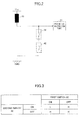
- the potential to be detected by the potential detector 171 is low. This case may apply to, for example, a situation where one end of the platen roller 20 is properly mounted whereas the other end of the platen roller 20 is not properly mounted to the predetermined position even if the cover is closed, or a situation where there is a malfunction due to a disconnection of one of the first and second detection switches 132, 142. In any of these situations, with the circuit illustrated in Fig. 5 , the potential detector 171 detects that the platen roller 20 not being mounted in the predetermined position. Therefore, with the circuit illustrated in Fig. 5 , the potential detector 171 is unable to determine whether the platen roller 20 is not mounted in the predetermined position or whether one of the first and second detection switches 132, 142 is disconnected.
- the second embodiment relates to a printer having the same structure as the printer 400 illustrated in Fig. 4 .
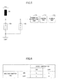
- resistors are connected to the ground side of the first and second detection switches 132, 142 as illustrated in Fig. 7 .
- resistors R11, R12, R21, and R22 are provided to the printer 400 of the second embodiment.
- One terminal of the first detection switch 132 is connected to a third resistor R21 and is grounded via the third resistor R21.
- a first resistor R11 is connected to the other terminal of the first detection switch 132.
- the potential of the power supply Vcc is applied to the first detection switch 132 via the first resistor R11.
- One terminal of the second detection switch 142 is connected to a fourth resistor R22 and is grounded via the fourth resistor R22.
- the other terminal of the second detection switch 142 is connected to a second resistor R12.
- a connection part between the one terminal of the first detection switch 132 and the third resistor R21 and a connection part between the one terminal of the second detection switch 142 and the fourth resistor R22 are connected to each other. These connection parts are also connected to the potential detector 171.
- the determination performed by the control part 172 is described based on Fig. 8 . If the platen roller 20 is mounted in a predetermined position when the cover is closed, the first and second detection switches 132, 142 are both switched off. Therefore, the potential detected by the potential detector 171 is 0 V.
- the potential detected by the potential detector 171 is V 2 if the platen roller 20 is disengaged from the predetermined position.
- the potential V 2 is a divided voltage divided by a resistance of the second resistor R12 and a combined resistance of the third and fourth resistors R21, R22.
- the potential V 2 can be calculated by the following Expression 2.
- V 2 R 21 ⁇ R 22 R 21 + R 22 R 12 + R 21 ⁇ R 22 R 21 + R 22 ⁇ Vcc
- the potential detected by the potential detector 171 is V 3 if the platen roller 20 is disengaged from the predetermined position.
- the potential V 3 is a divided voltage divided by a resistance of the first resistor R11 and a combined resistance of the third and fourth resistors R21, R22.
- the potential V 3 can be calculated by the following Expression 3.
- V 3 R 21 ⁇ R 22 R 21 + R 22 R 11 + R 21 ⁇ R 22 R 21 + R 22 ⁇ Vcc
- the control part 172 can determine that the platen roller 20 is mounted in the predetermined position.
- the control part 172 can determine that the platen roller 20 is not mounted in the predetermined position. Further, when the potential detected by the potential detector 171 is equal to or greater than the first threshold V t1 or if the potential detected by the potential detector 171 is equal to or less than the second threshold V t2 , the control part 172 can determine that there is a malfunction due to a disconnection of the first detection switch 132 or the second detection switch 142. The determination results of the control part 172 are displayed in the display part 173.
- control part 172 not only determines whether the platen roller 20 is mounted in the predetermined position but also determines whether there is a malfunction of one of the first and second detection switches 132, 142.
- the control part 172 can determine that there is a malfunction due to a disconnection of the first detection switch 132. In this case, the control part 172 can further determine which one of the first and second detection switches 132, 142 has malfunctioned.
- the control part can determine whether a short-circuit occurs by detecting divided voltage levels.
- a more detailed status determination can be performed by performing a determination in combination with the detection of other signals such as signals indicating a head-up (open-cover) state.
- the third resistor R21 and the fourth resistor R22 may be combined to be a single resistor.
- the combined single resistor is assumed to be a resistor positioned on the ground side.
- the resistance of the first resistor R11 is assumed as 0.75 k ⁇
- the resistance of the second resistor R12 is assumed as 1.2 k ⁇
- the resistance of the third resistor R21 is assumed as 0.47 k ⁇
- the resistance of the fourth resistor R22 is assumed as 1.2 k ⁇
- the voltage of the power supply Vcc is assumed as 2.8 V.
- the potential V 1 is approximately 1.9 V
- the potential V 2 is approximately 1.6 V
- the potential V 3 is approximately 1.2 V according to the Expressions 1-3.
- the control part 172 can determine that the platen roller 20 is mounted in the predetermined position. Further, if the potential detected by the potential detector 171 is higher than the second threshold (1.8 V), the control part 172 can determine that the platen roller 20 is not mounted in the predetermined position.
- the control part 172 can determine that there is a malfunction due to a disconnection of the second detection switch 142. Further, in a case where the potential detected by the potential detector 171 is greater than or equal to the third threshold (1.4 V) but less than or equal to the second threshold (1.8 V), the control part 172 can determine that there is a malfunction due to a disconnection of the first detection switch 132.
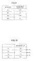
- control part 172 may also determine whether there is a malfunction due to short-circuiting of the first detection switch 132 or the second detection switch 142 by using the relationships illustrated in Figs. 9 and 10 .
- the control part 172 can determine whether the malfunction is due to a disconnection or short-circuiting by considering the detected potential in combination with status detection results from, for example, a head-up (open-cover) sensor.
Landscapes
- Accessory Devices And Overall Control Thereof (AREA)
- Handling Of Sheets (AREA)
- Electronic Switches (AREA)
Applications Claiming Priority (1)
| Application Number | Priority Date | Filing Date | Title |
|---|---|---|---|
| JP2013269260A JP6196550B2 (ja) | 2013-12-26 | 2013-12-26 | プリンタ装置及びプリンタ装置の制御方法 |
Publications (2)
| Publication Number | Publication Date |
|---|---|
| EP2933113A1 true EP2933113A1 (de) | 2015-10-21 |
| EP2933113B1 EP2933113B1 (de) | 2016-11-02 |
Family
ID=52282458
Family Applications (1)
| Application Number | Title | Priority Date | Filing Date |
|---|---|---|---|
| EP14199226.3A Not-in-force EP2933113B1 (de) | 2013-12-26 | 2014-12-19 | Drucker und Verfahren zur Steuerung eines Druckers |
Country Status (4)
| Country | Link |
|---|---|
| US (1) | US9283780B2 (de) |
| EP (1) | EP2933113B1 (de) |
| JP (1) | JP6196550B2 (de) |
| CN (1) | CN104742519B (de) |
Citations (5)
| Publication number | Priority date | Publication date | Assignee | Title |
|---|---|---|---|---|
| JPH10250130A (ja) | 1997-03-14 | 1998-09-22 | Canon Inc | サーマルラインプリンタの印字制御装置、サーマルラインプリンタの印字制御方法、及び印字装置 |
| EP1179433A2 (de) * | 2000-08-08 | 2002-02-13 | Fujitsu Takamisawa Component Limited | Thermodruckereinheit und Thermodrucker |
| JP2004210444A (ja) | 2002-12-27 | 2004-07-29 | Canon Semiconductor Equipment Inc | サーマルプリンタ |
| JP2008030253A (ja) | 2006-07-27 | 2008-02-14 | Fujitsu Component Ltd | プリント装置 |
| EP2353875A1 (de) * | 2010-02-02 | 2011-08-10 | Seiko Instruments Inc. | Drucker |
Family Cites Families (7)
| Publication number | Priority date | Publication date | Assignee | Title |
|---|---|---|---|---|
| JPS6068960A (ja) * | 1983-09-26 | 1985-04-19 | Canon Inc | 液体噴射記録装置及び該記録装置を用いた液体噴射記録方法 |
| JPH0648612A (ja) * | 1992-07-27 | 1994-02-22 | Canon Inc | 画像形成装置におけるジャム回復装置 |
| US5309176A (en) * | 1992-08-25 | 1994-05-03 | Sci Systems, Inc. | Airline ticket printer with stepper motor for selectively engaging print head and platen |
| JPH09248924A (ja) * | 1996-03-15 | 1997-09-22 | Tec Corp | サーマルプリンタ |
| JP2010214620A (ja) * | 2009-03-13 | 2010-09-30 | Oki Data Corp | カバー開閉検出回路及び画像形成装置 |
| JP5417257B2 (ja) * | 2010-05-31 | 2014-02-12 | 富士通コンポーネント株式会社 | 検出回路 |
| JP2013114132A (ja) * | 2011-11-30 | 2013-06-10 | Konica Minolta Business Technologies Inc | 定着装置および画像形成装置 |
-
2013
- 2013-12-26 JP JP2013269260A patent/JP6196550B2/ja not_active Expired - Fee Related
-
2014
- 2014-12-17 US US14/572,971 patent/US9283780B2/en not_active Expired - Fee Related
- 2014-12-19 CN CN201410802275.7A patent/CN104742519B/zh not_active Expired - Fee Related
- 2014-12-19 EP EP14199226.3A patent/EP2933113B1/de not_active Not-in-force
Patent Citations (5)
| Publication number | Priority date | Publication date | Assignee | Title |
|---|---|---|---|---|
| JPH10250130A (ja) | 1997-03-14 | 1998-09-22 | Canon Inc | サーマルラインプリンタの印字制御装置、サーマルラインプリンタの印字制御方法、及び印字装置 |
| EP1179433A2 (de) * | 2000-08-08 | 2002-02-13 | Fujitsu Takamisawa Component Limited | Thermodruckereinheit und Thermodrucker |
| JP2004210444A (ja) | 2002-12-27 | 2004-07-29 | Canon Semiconductor Equipment Inc | サーマルプリンタ |
| JP2008030253A (ja) | 2006-07-27 | 2008-02-14 | Fujitsu Component Ltd | プリント装置 |
| EP2353875A1 (de) * | 2010-02-02 | 2011-08-10 | Seiko Instruments Inc. | Drucker |
Also Published As
| Publication number | Publication date |
|---|---|
| CN104742519B (zh) | 2016-08-24 |
| US9283780B2 (en) | 2016-03-15 |
| JP2015123653A (ja) | 2015-07-06 |
| CN104742519A (zh) | 2015-07-01 |
| JP6196550B2 (ja) | 2017-09-13 |
| EP2933113B1 (de) | 2016-11-02 |
| US20150183241A1 (en) | 2015-07-02 |
Similar Documents
| Publication | Publication Date | Title |
|---|---|---|
| EP2604437B1 (de) | Drucksteuerverfahren und drucker | |
| US9990571B2 (en) | Media determining apparatus for determining transparency of a media, a media transport apparatus for detecting an end position of the medium and printing apparatus for controlling start of printing on a printing medium | |
| US7547087B2 (en) | Fault detection circuit for printers with multiple print heads | |
| US9908349B2 (en) | Printer | |
| JP2012016941A (ja) | インクジェットヘッド検査装置 | |
| KR20100130718A (ko) | 단일 전송 케이블로 신호를 송수신하는 전자 장치 | |
| EP2933113B1 (de) | Drucker und Verfahren zur Steuerung eines Druckers | |
| CN205643576U (zh) | 一种光电传感器的检测装置 | |
| US9931867B1 (en) | Method and system of determining a width of a printer ribbon | |
| GB2498828A (en) | Ink cartridge, set of ink cartridges, and ink cartridge determination system | |
| CN101371146A (zh) | 电压检测装置和电压检测方法 | |
| EP3386689B1 (de) | Schneiderzubehör für drucksystem | |
| US10035367B1 (en) | Single motor dynamic ribbon feedback system for a printer | |
| EP2894037B1 (de) | Verfahren zur Steuerung eines Druckers sowie Drucker | |
| US20190358962A1 (en) | Image forming apparatus | |
| US7582849B2 (en) | Thermal head, driving method and thermal head drive circuit | |
| JP2659571B2 (ja) | 紙送り装置 | |
| EP1755220B1 (de) | Schnittstellenschaltung | |
| JP7081853B1 (ja) | プリンタの印字濃度判定方法及び印字濃度判定装置 | |
| JP6704759B2 (ja) | 用紙脱落防止補助ユニット | |
| JP2000327146A (ja) | シート状態検出装置 | |
| JP2019166701A (ja) | プリンタ | |
| KR960027314A (ko) | 전자경비시스템의 프린팅 데이타 출력 버퍼회로 | |
| TW200922858A (en) | Print media detecting module | |
| JPH0958000A (ja) | インクジェットプリンタ |
Legal Events
| Date | Code | Title | Description |
|---|---|---|---|
| PUAI | Public reference made under article 153(3) epc to a published international application that has entered the european phase |
Free format text: ORIGINAL CODE: 0009012 |
|
| AK | Designated contracting states |
Kind code of ref document: A1 Designated state(s): AL AT BE BG CH CY CZ DE DK EE ES FI FR GB GR HR HU IE IS IT LI LT LU LV MC MK MT NL NO PL PT RO RS SE SI SK SM TR |
|
| AX | Request for extension of the european patent |
Extension state: BA ME |
|
| 17P | Request for examination filed |
Effective date: 20151119 |
|
| RBV | Designated contracting states (corrected) |
Designated state(s): AL AT BE BG CH CY CZ DE DK EE ES FI FR GB GR HR HU IE IS IT LI LT LU LV MC MK MT NL NO PL PT RO RS SE SI SK SM TR |
|
| RIC1 | Information provided on ipc code assigned before grant |
Ipc: B41J 11/04 20060101AFI20151210BHEP |
|
| GRAP | Despatch of communication of intention to grant a patent |
Free format text: ORIGINAL CODE: EPIDOSNIGR1 |
|
| INTG | Intention to grant announced |
Effective date: 20160118 |
|
| GRAP | Despatch of communication of intention to grant a patent |
Free format text: ORIGINAL CODE: EPIDOSNIGR1 |
|
| INTG | Intention to grant announced |
Effective date: 20160324 |
|
| GRAJ | Information related to disapproval of communication of intention to grant by the applicant or resumption of examination proceedings by the epo deleted |
Free format text: ORIGINAL CODE: EPIDOSDIGR1 |
|
| INTC | Intention to grant announced (deleted) | ||
| GRAR | Information related to intention to grant a patent recorded |
Free format text: ORIGINAL CODE: EPIDOSNIGR71 |
|
| GRAS | Grant fee paid |
Free format text: ORIGINAL CODE: EPIDOSNIGR3 |
|
| GRAA | (expected) grant |
Free format text: ORIGINAL CODE: 0009210 |
|
| AK | Designated contracting states |
Kind code of ref document: B1 Designated state(s): AL AT BE BG CH CY CZ DE DK EE ES FI FR GB GR HR HU IE IS IT LI LT LU LV MC MK MT NL NO PL PT RO RS SE SI SK SM TR |
|
| INTG | Intention to grant announced |
Effective date: 20160927 |
|
| REG | Reference to a national code |
Ref country code: GB Ref legal event code: FG4D |
|
| REG | Reference to a national code |
Ref country code: FR Ref legal event code: PLFP Year of fee payment: 3 |
|
| REG | Reference to a national code |
Ref country code: AT Ref legal event code: REF Ref document number: 841429 Country of ref document: AT Kind code of ref document: T Effective date: 20161115 Ref country code: CH Ref legal event code: EP |
|
| REG | Reference to a national code |
Ref country code: IE Ref legal event code: FG4D |
|
| REG | Reference to a national code |
Ref country code: DE Ref legal event code: R096 Ref document number: 602014004612 Country of ref document: DE |
|
| PG25 | Lapsed in a contracting state [announced via postgrant information from national office to epo] |
Ref country code: LV Free format text: LAPSE BECAUSE OF FAILURE TO SUBMIT A TRANSLATION OF THE DESCRIPTION OR TO PAY THE FEE WITHIN THE PRESCRIBED TIME-LIMIT Effective date: 20161102 |
|
| REG | Reference to a national code |
Ref country code: NL Ref legal event code: MP Effective date: 20161102 |
|
| REG | Reference to a national code |
Ref country code: LT Ref legal event code: MG4D |
|
| REG | Reference to a national code |
Ref country code: AT Ref legal event code: MK05 Ref document number: 841429 Country of ref document: AT Kind code of ref document: T Effective date: 20161102 |
|
| PG25 | Lapsed in a contracting state [announced via postgrant information from national office to epo] |
Ref country code: LT Free format text: LAPSE BECAUSE OF FAILURE TO SUBMIT A TRANSLATION OF THE DESCRIPTION OR TO PAY THE FEE WITHIN THE PRESCRIBED TIME-LIMIT Effective date: 20161102 Ref country code: SE Free format text: LAPSE BECAUSE OF FAILURE TO SUBMIT A TRANSLATION OF THE DESCRIPTION OR TO PAY THE FEE WITHIN THE PRESCRIBED TIME-LIMIT Effective date: 20161102 Ref country code: NL Free format text: LAPSE BECAUSE OF FAILURE TO SUBMIT A TRANSLATION OF THE DESCRIPTION OR TO PAY THE FEE WITHIN THE PRESCRIBED TIME-LIMIT Effective date: 20161102 Ref country code: NO Free format text: LAPSE BECAUSE OF FAILURE TO SUBMIT A TRANSLATION OF THE DESCRIPTION OR TO PAY THE FEE WITHIN THE PRESCRIBED TIME-LIMIT Effective date: 20170202 Ref country code: GR Free format text: LAPSE BECAUSE OF FAILURE TO SUBMIT A TRANSLATION OF THE DESCRIPTION OR TO PAY THE FEE WITHIN THE PRESCRIBED TIME-LIMIT Effective date: 20170203 |
|
| PG25 | Lapsed in a contracting state [announced via postgrant information from national office to epo] |
Ref country code: HR Free format text: LAPSE BECAUSE OF FAILURE TO SUBMIT A TRANSLATION OF THE DESCRIPTION OR TO PAY THE FEE WITHIN THE PRESCRIBED TIME-LIMIT Effective date: 20161102 Ref country code: ES Free format text: LAPSE BECAUSE OF FAILURE TO SUBMIT A TRANSLATION OF THE DESCRIPTION OR TO PAY THE FEE WITHIN THE PRESCRIBED TIME-LIMIT Effective date: 20161102 Ref country code: PT Free format text: LAPSE BECAUSE OF FAILURE TO SUBMIT A TRANSLATION OF THE DESCRIPTION OR TO PAY THE FEE WITHIN THE PRESCRIBED TIME-LIMIT Effective date: 20170302 Ref country code: FI Free format text: LAPSE BECAUSE OF FAILURE TO SUBMIT A TRANSLATION OF THE DESCRIPTION OR TO PAY THE FEE WITHIN THE PRESCRIBED TIME-LIMIT Effective date: 20161102 Ref country code: RS Free format text: LAPSE BECAUSE OF FAILURE TO SUBMIT A TRANSLATION OF THE DESCRIPTION OR TO PAY THE FEE WITHIN THE PRESCRIBED TIME-LIMIT Effective date: 20161102 Ref country code: AT Free format text: LAPSE BECAUSE OF FAILURE TO SUBMIT A TRANSLATION OF THE DESCRIPTION OR TO PAY THE FEE WITHIN THE PRESCRIBED TIME-LIMIT Effective date: 20161102 Ref country code: BE Free format text: LAPSE BECAUSE OF NON-PAYMENT OF DUE FEES Effective date: 20161231 Ref country code: PL Free format text: LAPSE BECAUSE OF FAILURE TO SUBMIT A TRANSLATION OF THE DESCRIPTION OR TO PAY THE FEE WITHIN THE PRESCRIBED TIME-LIMIT Effective date: 20161102 Ref country code: IS Free format text: LAPSE BECAUSE OF FAILURE TO SUBMIT A TRANSLATION OF THE DESCRIPTION OR TO PAY THE FEE WITHIN THE PRESCRIBED TIME-LIMIT Effective date: 20170302 |
|
| PG25 | Lapsed in a contracting state [announced via postgrant information from national office to epo] |
Ref country code: SK Free format text: LAPSE BECAUSE OF FAILURE TO SUBMIT A TRANSLATION OF THE DESCRIPTION OR TO PAY THE FEE WITHIN THE PRESCRIBED TIME-LIMIT Effective date: 20161102 Ref country code: DK Free format text: LAPSE BECAUSE OF FAILURE TO SUBMIT A TRANSLATION OF THE DESCRIPTION OR TO PAY THE FEE WITHIN THE PRESCRIBED TIME-LIMIT Effective date: 20161102 Ref country code: RO Free format text: LAPSE BECAUSE OF FAILURE TO SUBMIT A TRANSLATION OF THE DESCRIPTION OR TO PAY THE FEE WITHIN THE PRESCRIBED TIME-LIMIT Effective date: 20161102 Ref country code: CZ Free format text: LAPSE BECAUSE OF FAILURE TO SUBMIT A TRANSLATION OF THE DESCRIPTION OR TO PAY THE FEE WITHIN THE PRESCRIBED TIME-LIMIT Effective date: 20161102 Ref country code: EE Free format text: LAPSE BECAUSE OF FAILURE TO SUBMIT A TRANSLATION OF THE DESCRIPTION OR TO PAY THE FEE WITHIN THE PRESCRIBED TIME-LIMIT Effective date: 20161102 |
|
| REG | Reference to a national code |
Ref country code: DE Ref legal event code: R097 Ref document number: 602014004612 Country of ref document: DE |
|
| PG25 | Lapsed in a contracting state [announced via postgrant information from national office to epo] |
Ref country code: BG Free format text: LAPSE BECAUSE OF FAILURE TO SUBMIT A TRANSLATION OF THE DESCRIPTION OR TO PAY THE FEE WITHIN THE PRESCRIBED TIME-LIMIT Effective date: 20170202 Ref country code: IT Free format text: LAPSE BECAUSE OF FAILURE TO SUBMIT A TRANSLATION OF THE DESCRIPTION OR TO PAY THE FEE WITHIN THE PRESCRIBED TIME-LIMIT Effective date: 20161102 Ref country code: SM Free format text: LAPSE BECAUSE OF FAILURE TO SUBMIT A TRANSLATION OF THE DESCRIPTION OR TO PAY THE FEE WITHIN THE PRESCRIBED TIME-LIMIT Effective date: 20161102 Ref country code: BE Free format text: LAPSE BECAUSE OF FAILURE TO SUBMIT A TRANSLATION OF THE DESCRIPTION OR TO PAY THE FEE WITHIN THE PRESCRIBED TIME-LIMIT Effective date: 20161102 |
|
| PLBE | No opposition filed within time limit |
Free format text: ORIGINAL CODE: 0009261 |
|
| STAA | Information on the status of an ep patent application or granted ep patent |
Free format text: STATUS: NO OPPOSITION FILED WITHIN TIME LIMIT |
|
| PG25 | Lapsed in a contracting state [announced via postgrant information from national office to epo] |
Ref country code: MC Free format text: LAPSE BECAUSE OF FAILURE TO SUBMIT A TRANSLATION OF THE DESCRIPTION OR TO PAY THE FEE WITHIN THE PRESCRIBED TIME-LIMIT Effective date: 20161102 |
|
| REG | Reference to a national code |
Ref country code: IE Ref legal event code: MM4A |
|
| 26N | No opposition filed |
Effective date: 20170803 |
|
| PG25 | Lapsed in a contracting state [announced via postgrant information from national office to epo] |
Ref country code: LU Free format text: LAPSE BECAUSE OF NON-PAYMENT OF DUE FEES Effective date: 20161219 |
|
| REG | Reference to a national code |
Ref country code: FR Ref legal event code: PLFP Year of fee payment: 4 |
|
| PG25 | Lapsed in a contracting state [announced via postgrant information from national office to epo] |
Ref country code: SI Free format text: LAPSE BECAUSE OF FAILURE TO SUBMIT A TRANSLATION OF THE DESCRIPTION OR TO PAY THE FEE WITHIN THE PRESCRIBED TIME-LIMIT Effective date: 20161102 Ref country code: IE Free format text: LAPSE BECAUSE OF NON-PAYMENT OF DUE FEES Effective date: 20161219 |
|
| PG25 | Lapsed in a contracting state [announced via postgrant information from national office to epo] |
Ref country code: HU Free format text: LAPSE BECAUSE OF FAILURE TO SUBMIT A TRANSLATION OF THE DESCRIPTION OR TO PAY THE FEE WITHIN THE PRESCRIBED TIME-LIMIT; INVALID AB INITIO Effective date: 20141219 |
|
| PG25 | Lapsed in a contracting state [announced via postgrant information from national office to epo] |
Ref country code: CY Free format text: LAPSE BECAUSE OF FAILURE TO SUBMIT A TRANSLATION OF THE DESCRIPTION OR TO PAY THE FEE WITHIN THE PRESCRIBED TIME-LIMIT Effective date: 20161102 Ref country code: MK Free format text: LAPSE BECAUSE OF FAILURE TO SUBMIT A TRANSLATION OF THE DESCRIPTION OR TO PAY THE FEE WITHIN THE PRESCRIBED TIME-LIMIT Effective date: 20161102 |
|
| REG | Reference to a national code |
Ref country code: CH Ref legal event code: PL |
|
| PG25 | Lapsed in a contracting state [announced via postgrant information from national office to epo] |
Ref country code: MT Free format text: LAPSE BECAUSE OF NON-PAYMENT OF DUE FEES Effective date: 20161219 |
|
| PG25 | Lapsed in a contracting state [announced via postgrant information from national office to epo] |
Ref country code: TR Free format text: LAPSE BECAUSE OF FAILURE TO SUBMIT A TRANSLATION OF THE DESCRIPTION OR TO PAY THE FEE WITHIN THE PRESCRIBED TIME-LIMIT Effective date: 20161102 |
|
| PG25 | Lapsed in a contracting state [announced via postgrant information from national office to epo] |
Ref country code: CH Free format text: LAPSE BECAUSE OF NON-PAYMENT OF DUE FEES Effective date: 20171231 Ref country code: LI Free format text: LAPSE BECAUSE OF NON-PAYMENT OF DUE FEES Effective date: 20171231 |
|
| PGFP | Annual fee paid to national office [announced via postgrant information from national office to epo] |
Ref country code: DE Payment date: 20181204 Year of fee payment: 5 |
|
| PGFP | Annual fee paid to national office [announced via postgrant information from national office to epo] |
Ref country code: FR Payment date: 20181122 Year of fee payment: 5 Ref country code: GB Payment date: 20181219 Year of fee payment: 5 |
|
| REG | Reference to a national code |
Ref country code: DE Ref legal event code: R119 Ref document number: 602014004612 Country of ref document: DE |
|
| PG25 | Lapsed in a contracting state [announced via postgrant information from national office to epo] |
Ref country code: AL Free format text: LAPSE BECAUSE OF FAILURE TO SUBMIT A TRANSLATION OF THE DESCRIPTION OR TO PAY THE FEE WITHIN THE PRESCRIBED TIME-LIMIT Effective date: 20161102 |
|
| GBPC | Gb: european patent ceased through non-payment of renewal fee |
Effective date: 20191219 |
|
| PG25 | Lapsed in a contracting state [announced via postgrant information from national office to epo] |
Ref country code: DE Free format text: LAPSE BECAUSE OF NON-PAYMENT OF DUE FEES Effective date: 20200701 Ref country code: FR Free format text: LAPSE BECAUSE OF NON-PAYMENT OF DUE FEES Effective date: 20191231 Ref country code: GB Free format text: LAPSE BECAUSE OF NON-PAYMENT OF DUE FEES Effective date: 20191219 |