EP2933122A1 - Luftreifen - Google Patents
Luftreifen Download PDFInfo
- Publication number
- EP2933122A1 EP2933122A1 EP13870964.7A EP13870964A EP2933122A1 EP 2933122 A1 EP2933122 A1 EP 2933122A1 EP 13870964 A EP13870964 A EP 13870964A EP 2933122 A1 EP2933122 A1 EP 2933122A1
- Authority
- EP
- European Patent Office
- Prior art keywords
- pneumatic tire
- tire
- rubber
- carcass
- conductive yarn
- Prior art date
- Legal status (The legal status is an assumption and is not a legal conclusion. Google has not performed a legal analysis and makes no representation as to the accuracy of the status listed.)
- Granted
Links
Images



Classifications
-
- B—PERFORMING OPERATIONS; TRANSPORTING
- B60—VEHICLES IN GENERAL
- B60C—VEHICLE TYRES; TYRE INFLATION; TYRE CHANGING; CONNECTING VALVES TO INFLATABLE ELASTIC BODIES IN GENERAL; DEVICES OR ARRANGEMENTS RELATED TO TYRES
- B60C19/00—Tyre parts or constructions not otherwise provided for
- B60C19/08—Electric-charge-dissipating arrangements
- B60C19/082—Electric-charge-dissipating arrangements comprising a conductive tread insert
-
- B—PERFORMING OPERATIONS; TRANSPORTING
- B60—VEHICLES IN GENERAL
- B60C—VEHICLE TYRES; TYRE INFLATION; TYRE CHANGING; CONNECTING VALVES TO INFLATABLE ELASTIC BODIES IN GENERAL; DEVICES OR ARRANGEMENTS RELATED TO TYRES
- B60C19/00—Tyre parts or constructions not otherwise provided for
- B60C19/08—Electric-charge-dissipating arrangements
-
- B—PERFORMING OPERATIONS; TRANSPORTING
- B60—VEHICLES IN GENERAL
- B60C—VEHICLE TYRES; TYRE INFLATION; TYRE CHANGING; CONNECTING VALVES TO INFLATABLE ELASTIC BODIES IN GENERAL; DEVICES OR ARRANGEMENTS RELATED TO TYRES
- B60C19/00—Tyre parts or constructions not otherwise provided for
- B60C19/08—Electric-charge-dissipating arrangements
- B60C19/084—Electric-charge-dissipating arrangements using conductive carcasses
-
- B—PERFORMING OPERATIONS; TRANSPORTING
- B60—VEHICLES IN GENERAL
- B60C—VEHICLE TYRES; TYRE INFLATION; TYRE CHANGING; CONNECTING VALVES TO INFLATABLE ELASTIC BODIES IN GENERAL; DEVICES OR ARRANGEMENTS RELATED TO TYRES
- B60C5/00—Inflatable pneumatic tyres or inner tubes
-
- Y—GENERAL TAGGING OF NEW TECHNOLOGICAL DEVELOPMENTS; GENERAL TAGGING OF CROSS-SECTIONAL TECHNOLOGIES SPANNING OVER SEVERAL SECTIONS OF THE IPC; TECHNICAL SUBJECTS COVERED BY FORMER USPC CROSS-REFERENCE ART COLLECTIONS [XRACs] AND DIGESTS
- Y10—TECHNICAL SUBJECTS COVERED BY FORMER USPC
- Y10T—TECHNICAL SUBJECTS COVERED BY FORMER US CLASSIFICATION
- Y10T152/00—Resilient tires and wheels
- Y10T152/10—Tires, resilient
- Y10T152/10495—Pneumatic tire or inner tube
- Y10T152/10819—Characterized by the structure of the bead portion of the tire
Definitions
- the present invention relates to a pneumatic tire that may have a low electrical resistance.
- Patent Document 1 Japanese Unexamined Patent Application Publication No. H09-071112
- the present invention has been worked in light of the circumstance described above, and it is a main object thereof to provide a pneumatic tire having a low electrical resistance by providing a conductive yarn extending between a pair of bead cores.
- the present invention provides for a pneumatic tire including a tread portion, a pair of sidewall portions, a pair of bead portions each connected to an inner end of each sidewall portion and having a bead core therein, a toroidal carcass extending between the pair of bead cores, the carcass comprising a carcass ply comprising parallelly arranged carcass cords covered with a toping rubber, and a conductive yarn extending between the pair of bead cores along the topping rubber of the carcass ply.
- a plurality of conductive yarns may be arranged separately at intervals in a circumferential direction of the tire.
- the intervals are preferably in a range of from 80 to 120 mm.
- the conductive yarn is preferably arranged outwardly of the carcass ply between the bead cores.
- the conductive yarn preferably comprises a carbon fiber.
- the carbon fiber preferably has a fineness in a range of from 70 to 170 denier.
- the tread portion is preferably provided with a belt layer comprising parallelly arranged steel cords and arranged radially outwardly of the carcass, and a tread rubber including a rubber that has a volume resistivity value in a range of less than 10 8 ⁇ cm and is electrically communicated with the belt layer, and the conductive yarn is arranged in contact with the belt layer.
- the conductive yarn may extend in parallel to a radial direction of the tire.
- the conductive yarn may extend in a zigzag manner in a radial direction of the tire.
- the pneumatic tire in accordance with the present invention includes the troidal carcass extending between the pair of bead cores.
- the carcass includes the carcass ply comprising parallelly arranged carcass cords covered with a toping rubber.
- the pneumatic tire in accordance with the present invention includes an conductive yarn extending between the pair of bead cores along the topping rubber of the carcass ply.
- Such a pneumatic tire may have a low electrical resistance. Thus it is prevented to accumulate static electricity into a vehicle. Furthermore, since the conductive yarn extends between the pair of bead cores, it may provide a continuous and wide electrical conductive path extending from the tread portion to both sidewall portions. Thus the static electricity generated in the vehicle may be released to the ground through a rim by a simple configuration that a conductive rubber is arranged on the bead portion and the tread portion, for example.
- FIG. 1 illustrates a meridian cross-section, which includes a tire rotational axis, of a pneumatic tire 1 in accordance with the present embodiment 1 (hereinafter it may be referred as "tire") under a standard state.
- the standard state is such that the tire is the tire is mounted on a standard wheel rim (not shown) with a standard pressure and is loaded with no tire load.
- Various dimensions, positions and the like of the tire refer to those under the standard condition of the tire unless otherwise noted.
- the standard wheel rim is a wheel rim officially approved for the tire by standards organizations, wherein the standard wheel rim is the "standard rim” specified in JATMA, the "Design Rim” in TRA, and the “Measuring Rim” in ETRTO, for example.
- the standard pressure is the air pressure for the tire specified by the same organization, wherein the standard pressure is the "maximum air pressure” in JATMA, the maximum pressure given in the "Tire Load Limits at Various Cold Inflation Pressures” table in TRA, and the “Inflation Pressure” in ETRTO, for example.
- the pneumatic tire 1 in accordance with the present embodiment includes a tread portion 2, a pair of sidewall portions 3, and a pair of bead portions 4 each with a bead core 5 therein and each connected to a radially inner end of each sidewall portion 3.
- the pneumatic tire 1 in accordance with the present embodiment is provided with a toroidal carcass 6 extending between the pair of bead cores 5, and a belt layer 7 disposed radially outwardly of the carcass 6 in the tread portion 2.
- a pneumatic tire for passenger cars is illustrated.
- the carcass 6 includes, at least one, a single carcass ply 6A in this embodiment.
- the carcass ply 6A includes parallelly arranged carcass cords covered with a toping rubber.
- the carcass ply 6A includes a main portion 6a extending from the tread portion 2 to the bead core 5 of the bead portions 4 through the sidewall portions 3, and a turn-up portions 6b each turned up around the bead core 5 from axially inside to outside of the tire.
- a bead apex rubber 8 which is made of a hard rubber and extends radially outwardly from the bead core 5 is disposed between the main portion 6a and the turn-up portion 6b. With this, the bead portion 4 is suitably reinforced.
- organic fiber cords such as aramid, rayon and the like may be used.
- the carcass cords for example, are arranged at an angle of from 70 to 90 degrees with respect to the tire equator C.
- the topping rubber of the carcass ply 6A contains carbon black as reinforcing agent for rubber same as conventional tires.
- the carcass ply 6A has a volume specific electrical resistance value in a range of less than 10 8 ⁇ •cm, more preferably less than 10 7 ⁇ •cm, thereby having sufficient conductivity.
- rubber having conductivity means rubber having a volume specific electrical resistance value of less than 10 8 ⁇ •cm.
- rubber having non-conductivity means rubber having a volume specific electrical resistance value of not less than 10 8 ⁇ •cm.
- the belt layer 7 includes at least one belt ply of belt cords arranged at an angle of from 10 to 40 degrees with respect to the tire equator C.
- the belt layer 7 includes radially inner and outer belt plies 7A and 7B which are overlapped one another so that each belt cords of plies crosses.
- Each of the belt plies 7A and 7B is formed of belt cords covered with a topping rubber.
- the topping rubber for the belt layer is used the same one as the topping rubber of the carcass ply 6A.
- a steel cord is used for the belt cords.
- high modulus organic fiber cords such as aramid, rayon and the like may be used for the belt cords as needed.
- the pneumatic tire 1 in accordance with the present embodiment includes a tread rubber 11 arranged radially outward of the belt layer 7, a sidewall rubber 12 arranged axially outward of the carcass 6 in each sidewall portion 3, a clinch rubber 13 for preventing deviation against the rim arranged axially outward of the bead portion 4, and an inner liner rubber 14 with air impermeable property forming a cavity surface 15 of the tire.
- a rubber composition containing a lot of silica for reinforcing rubber may be used same as the traditional tire.
- These rubber has a volume specific electrical resistance value in a range of from 10 8 to 10 9 ⁇ •cm, for example.
- a rubber composition containing a lot of carbon black for reinforcing rubber may be used. These rubber has a volume specific electrical resistance value in a range of from 10 6 to 10 7 ⁇ •cm, for example.
- the pneumatic tire 1 in accordance with the present embodiment is provided with an conductive yarn 10 extending between the bead cores along the topping rubber of the carcass ply 6A.
- the conductive yarns 10 are arranged in a troidal manner.
- the conductive yarn 10 has a small electrical resistance value.
- the pneumatic tire 1 also has a small electrical resistance, thereby preventing accumulation of the static electricity into the vehicle.
- the conductive yarn 10 since the conductive yarn 10 extends between the pair of bead cores 5, it may provide a long electrically conductive path continuing from the tread portion 2 to both sidewall portions 3. Accordingly, the static electricity generated in the vehicle may be released to the ground through a rim by a simple configuration that a conductive rubber is arranged on the bead portion 4 and the tread portion 2, for example.
- the conductive yarn 10 is disposed in radially outside the main portion 6a of the carcass ply 6A.
- the conductive yarn 10 extends from the tread portion 2 through the sidewall portions 3 to the bead portions 4, wherein the yarn 10 further extends to the radially outermost edge 16 of the turn-up portion 6b along the turn-up portion 6b passing through below the bead core 5.
- This configuration where the conductive yarn 10 is turned up around the bead portions 4 may effectively lower the electrical resistance of the bead portion 4.
- FIGS. 2a and 2b each illustrates a side perspective view of the tire 1.
- a plurality of conductive yarns 10 are arranged separately at intervals in a circumferential direction of the tire, as shown in FIG. 2a .
- the conductive yarns 10 in accordance with the embodiment shown in FIG. 2a extend in parallel to a radial direction of the tire in a straight manner.
- the conductive yarns 10 are arranged at equal intervals in the circumferential direction of the tire.
- the conductive yarns 10 may lower the electrical resistance of the tire 1 uniformly, and may provide an electrical conductive path in a large range continuing from the tread portion 2 to the sidewall portion 3.
- the conductive yarns 10 may extend in a zigzag or wavy manner with respect to the radial direction of the tire. Such a conductive yarn 10 may be longer than the one shown in FIG. 2a , thereby effectively preventing accumulation of static electricity in a vehicle.
- the intervals d between adjacent conductive yarns in the circumferential direction of the tire 1 are preferably not less than 80 mm, more preferably not less than 90 mm, but preferably not more than 120 mm, more preferably not more than 110 mm.
- Each of the intervals d means an interval at the position where the interval between adjacent conductive yarns 10 is the maximum, wherein the position is at the tire equator C in this embodiment.
- productivity of the tire tends to lower.
- the interval d is large, it may be difficult to lower the electrical resistance of the tire.
- FIGS. 3a and 3b each illustrates an enlarged perspective view of the carcass ply 6A with conductive yarns 10.
- the conductive yarns 10 are preferably arranged on the outer surface 21s of the topping rubber 21 along with the longitudinal direction of the carcass cords 22.
- FIG. 4 illustrates a cross sectional view taken along a line A-A of FIG. 1 .
- the conductive yarn 10 offers very small gap 24 extending along the yarn 10 between the sidewall rubber 12 and the carcass ply 6A.
- Such small gap 24 may suppress air remaining failure by discharging the air remaining between the outer surface 21s of the topping rubber 21 and the inner surface 12s of the sidewall rubber 12 outside along the yarn 10.
- the conductive yarn 10 refers to the yarn having a volume specific electrical resistance value in a range of not more than 10 6 ⁇ •cm.
- the volume specific electrical resistance value of the conductive yarn 10 is preferably not more than 10 5 ⁇ •cm, more preferably, not more than 10 4 ⁇ •cm, thereby efficiently lowering the electrical resistance of the tire.
- carbon fiber is preferably employed, for example.
- the carbon fiber has not only excellent conductivity but also high durability against repeated deformation of the tire.
- the conductive yarn preferably has a fineness in a range of not less than 70 denier, more preferably not less than 75 denier, but preferably not more than 170 denier, more preferably not more than 110 denier.
- the conductive yarn 10 is excessively small, the yarn may be cut off due to strain during tire traveling.
- the conductive yarn 10 has excessively large fineness, a dent and/or bulge may be appeared on the sidewall portion 3 due to the conductive yarn 10, thereby lowering appearance of the tire.
- the tread rubber 11 shown in FIG. 1 preferably includes a rubber composition that has a volume specific electrical resistance value in a range of less than 10 8 ⁇ cm and that is electrically communicated with the belt layer 7.
- the tread rubber 11 may electrically communicated with the conductive yarn through the belt layer 7 and the topping rubber of the carcass ply 6A, thereby further lowering the electrical resistance of the tire.
- the tread rubber 11 may include a silica rich rubber composition. In this case, the tread rubber 11 tends to have high electrical resistance.
- the tread portion 2 may include a terminal portion 25 that electrically connects the ground with the belt layer 7.
- the terminal portion 25 is made of a conductive rubber that includes one end exposed at the tread ground contacting surface 2s and the other end connected to the belt layer 7.
- the terminal portion 25 is an accessorial rubber portion formed as a columnar shape or a circumferentially extending rib shape.
- Such a tread portion 2 may offer a low rolling resistance while discharging the static electricity accumulated in the vehicle.
- the conductive yarn 10 may be arranged on the side of the cavity surface 15 of the main portion 6a of the carcass ply 6A.
- the conductive yarn 10 since the conductive yarn 10 may electrically communicated with the conductive clinch rubber 13 in the bead portion 4, the tire may efficiently discharge the static electricity accumulated in the vehicle to the ground.
- the conductive yarn 10 as mentioned above does not produce neither a dent nor bulge on the outer surface of the sidewall portion 3, even under a condition where a large number of yarns with a large fineness are provided, thereby providing excellent appearance of the tire.
- the conductive yarn 10 may be arranged on radially both sides of the main portion 6a. This configuration may provide wider conductive path region so that the static electricity in the vehicle is efficiently discharge to the ground.
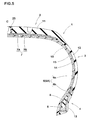
- Pneumatic tires for passenger cars having a size of 195/65R15 and the basic structure shown in FIGS. 1 , 5 and 6 were manufactured based on the specifications of Table 1 and then tested for electrical resistance of the tire, appearance of the sidewall portion, and productivity.
- Ref. 1 the tire which is not provided with the conductive yarn was also tested in the same manner. Test methods are as follows.
- the electric resistance value of the assembly of each test tire T and the rim R was measured according to the procedure specified by JATMA using a measurement device.
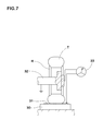
- the measurement device includes an insulating plate 30 with electrical resistance value greater than 10 12 ⁇ , a polished metal plate 31 with electrical resistance value less than 10 ⁇ arranged on the insulating plate 30, a conductive mounting axle 32 for supporting the tire and rim assembly, and a ohm meter 33.
- Each test tire T was cleaned up to remove a mold release agent, dust and the like from the tire surface, and completely dried. Measurement conditions are as follows.
- Rim material Aluminum alloy Rim size: 17x7J Internal pressure: 200 kPa Tire load: 5.3 kN Testing environment temperature (temperature of testing room): 25 degrees C. Humidity: 50% Measurement range of ohm meter: 1.0x10 3 to 1.6 ⁇ 10 16 ⁇ Testing voltage (applied voltage): 1000 V
- test procedure are as follows:
Landscapes
- Engineering & Computer Science (AREA)
- Mechanical Engineering (AREA)
- Tires In General (AREA)
Applications Claiming Priority (2)
| Application Number | Priority Date | Filing Date | Title |
|---|---|---|---|
| JP2013002054A JP5841551B2 (ja) | 2013-01-09 | 2013-01-09 | 空気入りタイヤ |
| PCT/JP2013/083349 WO2014109169A1 (ja) | 2013-01-09 | 2013-12-12 | 空気入りタイヤ |
Publications (3)
| Publication Number | Publication Date |
|---|---|
| EP2933122A1 true EP2933122A1 (de) | 2015-10-21 |
| EP2933122A4 EP2933122A4 (de) | 2016-10-05 |
| EP2933122B1 EP2933122B1 (de) | 2018-04-25 |
Family
ID=51166830
Family Applications (1)
| Application Number | Title | Priority Date | Filing Date |
|---|---|---|---|
| EP13870964.7A Active EP2933122B1 (de) | 2013-01-09 | 2013-12-12 | Luftreifen |
Country Status (5)
| Country | Link |
|---|---|
| US (1) | US20150328941A1 (de) |
| EP (1) | EP2933122B1 (de) |
| JP (1) | JP5841551B2 (de) |
| CN (1) | CN104884279B (de) |
| WO (1) | WO2014109169A1 (de) |
Cited By (6)
| Publication number | Priority date | Publication date | Assignee | Title |
|---|---|---|---|---|
| CN108463361A (zh) * | 2016-01-13 | 2018-08-28 | 株式会社普利司通 | 充气轮胎 |
| WO2019116615A1 (ja) | 2017-12-13 | 2019-06-20 | 株式会社ブリヂストン | 空気入りタイヤ |
| EP2988956B1 (de) * | 2013-04-24 | 2020-01-15 | Continental Reifen Deutschland GmbH | Fahrzeugluftreifen und verfahren zur herstellung eines fahrzeugluftreifens |
| IT201900023286A1 (it) * | 2019-12-06 | 2021-06-06 | Iginio Benedetti | Pneumatico per autoveicoli atto alla conduzione di corrente elettrica e autoveicoli comprendenti ruote con detto pneumatico |
| EP3785948A4 (de) * | 2018-04-23 | 2021-12-22 | Bridgestone Corporation | Reifen |
| EP3966044A4 (de) * | 2019-05-07 | 2023-03-22 | Cooper Tire & Rubber Company | Elektrisch leitfähige laufflächenverbindung |
Families Citing this family (32)
| Publication number | Priority date | Publication date | Assignee | Title |
|---|---|---|---|---|
| JP2575414Y2 (ja) | 1994-03-10 | 1998-06-25 | 富士電機冷機 株式会社 | 自動販売機の扉構造 |
| JP2546300Y2 (ja) | 1994-03-10 | 1997-08-27 | 富士電機冷機株式会社 | 自動販売機の扉構造 |
| JP6040067B2 (ja) * | 2013-03-21 | 2016-12-07 | 東洋ゴム工業株式会社 | 空気入りタイヤの製造方法及び空気入りタイヤ |
| JP6075285B2 (ja) | 2013-12-26 | 2017-02-08 | 横浜ゴム株式会社 | 空気入りタイヤ |
| JP5970032B2 (ja) * | 2014-08-06 | 2016-08-17 | 住友ゴム工業株式会社 | プライ材料の製造方法 |
| US11453255B2 (en) | 2014-09-05 | 2022-09-27 | The Yokohama Rubber Co., Ltd. | Pneumatic tire with electrically conductive rubber within rim cushion rubber |
| JP6413910B2 (ja) * | 2015-04-23 | 2018-10-31 | 横浜ゴム株式会社 | 空気入りタイヤ |
| EP3307559B1 (de) | 2015-06-15 | 2021-02-17 | Bridgestone Americas Tire Operations, LLC | Reifen mit einer leiterbahn |
| EP3307558B1 (de) * | 2015-06-15 | 2020-11-18 | Bridgestone Americas Tire Operations, LLC | Reifen mit einem leitenden einsatz |
| JP6544140B2 (ja) * | 2015-08-24 | 2019-07-17 | 住友ゴム工業株式会社 | 空気入りタイヤ及びその製造方法 |
| JP6164268B2 (ja) * | 2015-09-30 | 2017-07-19 | 横浜ゴム株式会社 | 空気入りタイヤ及びその製造方法 |
| DE102015220492A1 (de) * | 2015-10-21 | 2017-04-27 | Continental Reifen Deutschland Gmbh | Fahrzeugluftreifen |
| KR101791202B1 (ko) * | 2016-01-11 | 2017-10-27 | 한국타이어 주식회사 | 시트 및 이를 포함하는 타이어 |
| JP6758046B2 (ja) * | 2016-01-13 | 2020-09-23 | 株式会社ブリヂストン | 空気入りタイヤ |
| WO2018011001A1 (en) * | 2016-07-15 | 2018-01-18 | Nv Bekaert Sa | Electrically conductive yarn |
| JP6768441B2 (ja) * | 2016-10-11 | 2020-10-14 | Toyo Tire株式会社 | 空気入りタイヤ |
| WO2018111650A1 (en) * | 2016-12-13 | 2018-06-21 | Bridgestone Americas Tire Operations, Llc | Tire having a conductive cord |
| JP6930262B2 (ja) * | 2017-07-18 | 2021-09-01 | 横浜ゴム株式会社 | 空気入りタイヤ及び空気入りタイヤの製造方法 |
| KR102007869B1 (ko) * | 2017-11-28 | 2019-08-06 | 금호타이어 주식회사 | 공기입 타이어 |
| EP3727897B1 (de) * | 2017-12-22 | 2021-12-01 | Compagnie Générale des Etablissements Michelin | Reifen mit leitfähigem kord |
| EP3501847B1 (de) * | 2017-12-22 | 2020-11-11 | Hankook Tire Co., Ltd. | Kordverstärkte lage für einen reifen, verfahren zur herstellung derselbe und reifen damit |
| KR102139362B1 (ko) * | 2018-10-26 | 2020-07-29 | 한국타이어앤테크놀로지 주식회사 | 타이어 코드 직물, 이의 제조 방법, 이를 포함하는 시트 및 상기 시트를 포함하는 타이어 |
| CN109747347A (zh) * | 2019-03-01 | 2019-05-14 | 正新橡胶(中国)有限公司 | 一种充气轮胎及其制作方法 |
| JP7161975B2 (ja) | 2019-06-19 | 2022-10-27 | 株式会社ブリヂストン | タイヤ |
| JP7181158B2 (ja) * | 2019-06-21 | 2022-11-30 | 株式会社ブリヂストン | タイヤ |
| JP7181159B2 (ja) * | 2019-06-21 | 2022-11-30 | 株式会社ブリヂストン | タイヤ |
| JP7207240B2 (ja) * | 2019-09-03 | 2023-01-18 | 横浜ゴム株式会社 | 空気入りタイヤ及びグリーンタイヤの製造方法 |
| KR102267900B1 (ko) * | 2019-09-24 | 2021-06-24 | 한국타이어앤테크놀로지 주식회사 | 금속염이 도금된 섬유를 포함하는 비공기입 타이어 |
| KR102414422B1 (ko) * | 2020-11-04 | 2022-06-28 | 한국타이어앤테크놀로지 주식회사 | 탄소섬유 방적사를 포함하는 타이어 및 그의 제조방법 |
| US12583265B2 (en) | 2020-12-15 | 2026-03-24 | Sumitomo Rubber Industries, Ltd. | Pneumatic tire |
| JP7733549B2 (ja) * | 2021-11-18 | 2025-09-03 | 株式会社ブリヂストン | タイヤ |
| JP7780078B2 (ja) | 2021-11-24 | 2025-12-04 | 横浜ゴム株式会社 | タイヤ |
Family Cites Families (17)
| Publication number | Priority date | Publication date | Assignee | Title |
|---|---|---|---|---|
| JPH01293208A (ja) * | 1988-05-20 | 1989-11-27 | K S K Control Kk | 静電気放電用自動車タイヤ |
| GB9409453D0 (en) * | 1994-05-12 | 1994-06-29 | Sumitomo Rubber Ind | tyre tread and tyres incorporating them |
| JP3585266B2 (ja) * | 1994-09-08 | 2004-11-04 | 株式会社丸吉エンジニアリング | 面状発熱体を使用した暖房設備の施工方法 |
| JP3477297B2 (ja) | 1994-12-21 | 2003-12-10 | 住友ゴム工業株式会社 | 空気入りタイヤ |
| JP3337415B2 (ja) * | 1998-03-04 | 2002-10-21 | 住友ゴム工業株式会社 | 氷上走行に適した空気入りタイヤ |
| JP2004268863A (ja) * | 2003-03-12 | 2004-09-30 | Yokohama Rubber Co Ltd:The | 空気入りタイヤ |
| US7284582B2 (en) * | 2003-10-23 | 2007-10-23 | The Goodyear Tire & Rubber Company | Pneumatic tire with electrically conductive cord extending between a bead portion and a tread portion of the tire |
| JP4643189B2 (ja) * | 2004-07-09 | 2011-03-02 | 東洋ゴム工業株式会社 | ゴム組成物及び空気入りタイヤ |
| JP4464917B2 (ja) * | 2005-12-28 | 2010-05-19 | 住友ゴム工業株式会社 | 空気入りタイヤ |
| JP4118307B2 (ja) * | 2006-04-04 | 2008-07-16 | 住友ゴム工業株式会社 | 空気入りタイヤ |
| FR2933032B1 (fr) * | 2008-06-25 | 2010-06-18 | Michelin Soc Tech | Pneumatique comportant des melanges non conducteurs de l'electricite et un chemin permettant l'ecoulement des charges. |
| FR2940183B1 (fr) * | 2008-12-22 | 2011-03-04 | Michelin Soc Tech | Pneumatique comportant des cables d'armature de carcasse presentant une faible permeabilite, et des fils textiles associes a l'armature de carcasse |
| DE102010017444A1 (de) * | 2010-06-18 | 2011-12-22 | Continental Reifen Deutschland Gmbh | Fahrzeugluftreifen mit Luftabführungsfäden und Verfahren zur Herstellung einer elektrisch leitfähigen Beschichtung für die Luftabführungsfäden |
| DE102010017443A1 (de) * | 2010-06-18 | 2011-12-22 | Continental Reifen Deutschland Gmbh | Fahrzeugluftreifen |
| DE102010037711B4 (de) * | 2010-09-22 | 2023-05-04 | Continental Reifen Deutschland Gmbh | Verfahren zur Herstellung eines Fahrzeugluftreifens |
| JP5554250B2 (ja) * | 2011-01-13 | 2014-07-23 | 東洋ゴム工業株式会社 | 空気入りタイヤの製造方法及び空気入りタイヤ |
| US20130056128A1 (en) * | 2011-09-06 | 2013-03-07 | Carlo Kanz | Pneumatic tire with conductive bleeder cords |
-
2013
- 2013-01-09 JP JP2013002054A patent/JP5841551B2/ja active Active
- 2013-12-12 WO PCT/JP2013/083349 patent/WO2014109169A1/ja not_active Ceased
- 2013-12-12 US US14/653,545 patent/US20150328941A1/en not_active Abandoned
- 2013-12-12 CN CN201380068107.3A patent/CN104884279B/zh active Active
- 2013-12-12 EP EP13870964.7A patent/EP2933122B1/de active Active
Cited By (8)
| Publication number | Priority date | Publication date | Assignee | Title |
|---|---|---|---|---|
| EP2988956B1 (de) * | 2013-04-24 | 2020-01-15 | Continental Reifen Deutschland GmbH | Fahrzeugluftreifen und verfahren zur herstellung eines fahrzeugluftreifens |
| CN108463361A (zh) * | 2016-01-13 | 2018-08-28 | 株式会社普利司通 | 充气轮胎 |
| EP3403855A4 (de) * | 2016-01-13 | 2019-01-23 | Bridgestone Corporation | Luftreifen |
| CN108463361B (zh) * | 2016-01-13 | 2020-09-08 | 株式会社普利司通 | 充气轮胎 |
| WO2019116615A1 (ja) | 2017-12-13 | 2019-06-20 | 株式会社ブリヂストン | 空気入りタイヤ |
| EP3785948A4 (de) * | 2018-04-23 | 2021-12-22 | Bridgestone Corporation | Reifen |
| EP3966044A4 (de) * | 2019-05-07 | 2023-03-22 | Cooper Tire & Rubber Company | Elektrisch leitfähige laufflächenverbindung |
| IT201900023286A1 (it) * | 2019-12-06 | 2021-06-06 | Iginio Benedetti | Pneumatico per autoveicoli atto alla conduzione di corrente elettrica e autoveicoli comprendenti ruote con detto pneumatico |
Also Published As
| Publication number | Publication date |
|---|---|
| EP2933122A4 (de) | 2016-10-05 |
| CN104884279B (zh) | 2018-02-02 |
| CN104884279A (zh) | 2015-09-02 |
| US20150328941A1 (en) | 2015-11-19 |
| JP5841551B2 (ja) | 2016-01-13 |
| WO2014109169A1 (ja) | 2014-07-17 |
| JP2014133467A (ja) | 2014-07-24 |
| EP2933122B1 (de) | 2018-04-25 |
Similar Documents
| Publication | Publication Date | Title |
|---|---|---|
| EP2933122B1 (de) | Luftreifen | |
| EP1803589B1 (de) | Luftreifen | |
| EP2230105B1 (de) | Luftreifen mit der Fähigkeit des Ableitens von statischer Elektrizität und Herstellungsverfahren dafür | |
| JP4392444B2 (ja) | 空気入りタイヤ及びその製造方法 | |
| KR101587310B1 (ko) | 공기 타이어 및 그 제조 방법 | |
| EP3725568A1 (de) | Luftreifen | |
| US11453255B2 (en) | Pneumatic tire with electrically conductive rubber within rim cushion rubber | |
| JP5266132B2 (ja) | 空気入りタイヤ | |
| EP3375645B1 (de) | Luftreifen und herstellungsverfahren dafür | |
| US10850574B2 (en) | Pneumatic tire | |
| JP2015171848A (ja) | 空気入りタイヤ | |
| CN105307876B (zh) | 充气轮胎 | |
| CN100333928C (zh) | 充气轮胎 | |
| JP5624369B2 (ja) | 空気入りタイヤ及びその製造方法 | |
| EP2837511B1 (de) | Luftreifen | |
| JP2017043122A (ja) | 空気入りタイヤ及びその製造方法 | |
| JP6759703B2 (ja) | 空気入りタイヤ及びその製造方法 | |
| JP6458499B2 (ja) | 空気入りタイヤ | |
| JP2014172583A (ja) | 空気入りタイヤ | |
| JP2015217868A (ja) | 空気入りタイヤ | |
| JP4571664B2 (ja) | 空気入りタイヤ及びその製造方法 | |
| JP2018111371A (ja) | 空気入りタイヤ | |
| JP6435725B2 (ja) | 空気入りタイヤ | |
| JP6476668B2 (ja) | 空気入りタイヤ |
Legal Events
| Date | Code | Title | Description |
|---|---|---|---|
| PUAI | Public reference made under article 153(3) epc to a published international application that has entered the european phase |
Free format text: ORIGINAL CODE: 0009012 |
|
| 17P | Request for examination filed |
Effective date: 20150715 |
|
| AK | Designated contracting states |
Kind code of ref document: A1 Designated state(s): AL AT BE BG CH CY CZ DE DK EE ES FI FR GB GR HR HU IE IS IT LI LT LU LV MC MK MT NL NO PL PT RO RS SE SI SK SM TR |
|
| AX | Request for extension of the european patent |
Extension state: BA ME |
|
| DAX | Request for extension of the european patent (deleted) | ||
| A4 | Supplementary search report drawn up and despatched |
Effective date: 20160901 |
|
| RIC1 | Information provided on ipc code assigned before grant |
Ipc: B60C 19/08 20060101AFI20160826BHEP Ipc: B60C 11/00 20060101ALI20160826BHEP |
|
| STAA | Information on the status of an ep patent application or granted ep patent |
Free format text: STATUS: EXAMINATION IS IN PROGRESS |
|
| 17Q | First examination report despatched |
Effective date: 20170425 |
|
| GRAP | Despatch of communication of intention to grant a patent |
Free format text: ORIGINAL CODE: EPIDOSNIGR1 |
|
| STAA | Information on the status of an ep patent application or granted ep patent |
Free format text: STATUS: GRANT OF PATENT IS INTENDED |
|
| INTG | Intention to grant announced |
Effective date: 20171026 |
|
| GRAJ | Information related to disapproval of communication of intention to grant by the applicant or resumption of examination proceedings by the epo deleted |
Free format text: ORIGINAL CODE: EPIDOSDIGR1 |
|
| STAA | Information on the status of an ep patent application or granted ep patent |
Free format text: STATUS: EXAMINATION IS IN PROGRESS |
|
| GRAP | Despatch of communication of intention to grant a patent |
Free format text: ORIGINAL CODE: EPIDOSNIGR1 |
|
| STAA | Information on the status of an ep patent application or granted ep patent |
Free format text: STATUS: GRANT OF PATENT IS INTENDED |
|
| INTC | Intention to grant announced (deleted) | ||
| INTG | Intention to grant announced |
Effective date: 20180202 |
|
| GRAA | (expected) grant |
Free format text: ORIGINAL CODE: 0009210 |
|
| GRAS | Grant fee paid |
Free format text: ORIGINAL CODE: EPIDOSNIGR3 |
|
| STAA | Information on the status of an ep patent application or granted ep patent |
Free format text: STATUS: THE PATENT HAS BEEN GRANTED |
|
| AK | Designated contracting states |
Kind code of ref document: B1 Designated state(s): AL AT BE BG CH CY CZ DE DK EE ES FI FR GB GR HR HU IE IS IT LI LT LU LV MC MK MT NL NO PL PT RO RS SE SI SK SM TR |
|
| REG | Reference to a national code |
Ref country code: GB Ref legal event code: FG4D |
|
| REG | Reference to a national code |
Ref country code: CH Ref legal event code: EP |
|
| REG | Reference to a national code |
Ref country code: AT Ref legal event code: REF Ref document number: 992467 Country of ref document: AT Kind code of ref document: T Effective date: 20180515 |
|
| REG | Reference to a national code |
Ref country code: IE Ref legal event code: FG4D |
|
| REG | Reference to a national code |
Ref country code: DE Ref legal event code: R096 Ref document number: 602013036703 Country of ref document: DE |
|
| REG | Reference to a national code |
Ref country code: NL Ref legal event code: MP Effective date: 20180425 |
|
| REG | Reference to a national code |
Ref country code: LT Ref legal event code: MG4D |
|
| PG25 | Lapsed in a contracting state [announced via postgrant information from national office to epo] |
Ref country code: NL Free format text: LAPSE BECAUSE OF FAILURE TO SUBMIT A TRANSLATION OF THE DESCRIPTION OR TO PAY THE FEE WITHIN THE PRESCRIBED TIME-LIMIT Effective date: 20180425 |
|
| PG25 | Lapsed in a contracting state [announced via postgrant information from national office to epo] |
Ref country code: FI Free format text: LAPSE BECAUSE OF FAILURE TO SUBMIT A TRANSLATION OF THE DESCRIPTION OR TO PAY THE FEE WITHIN THE PRESCRIBED TIME-LIMIT Effective date: 20180425 Ref country code: BG Free format text: LAPSE BECAUSE OF FAILURE TO SUBMIT A TRANSLATION OF THE DESCRIPTION OR TO PAY THE FEE WITHIN THE PRESCRIBED TIME-LIMIT Effective date: 20180725 Ref country code: LT Free format text: LAPSE BECAUSE OF FAILURE TO SUBMIT A TRANSLATION OF THE DESCRIPTION OR TO PAY THE FEE WITHIN THE PRESCRIBED TIME-LIMIT Effective date: 20180425 Ref country code: PL Free format text: LAPSE BECAUSE OF FAILURE TO SUBMIT A TRANSLATION OF THE DESCRIPTION OR TO PAY THE FEE WITHIN THE PRESCRIBED TIME-LIMIT Effective date: 20180425 Ref country code: NO Free format text: LAPSE BECAUSE OF FAILURE TO SUBMIT A TRANSLATION OF THE DESCRIPTION OR TO PAY THE FEE WITHIN THE PRESCRIBED TIME-LIMIT Effective date: 20180725 Ref country code: SE Free format text: LAPSE BECAUSE OF FAILURE TO SUBMIT A TRANSLATION OF THE DESCRIPTION OR TO PAY THE FEE WITHIN THE PRESCRIBED TIME-LIMIT Effective date: 20180425 Ref country code: ES Free format text: LAPSE BECAUSE OF FAILURE TO SUBMIT A TRANSLATION OF THE DESCRIPTION OR TO PAY THE FEE WITHIN THE PRESCRIBED TIME-LIMIT Effective date: 20180425 |
|
| PG25 | Lapsed in a contracting state [announced via postgrant information from national office to epo] |
Ref country code: GR Free format text: LAPSE BECAUSE OF FAILURE TO SUBMIT A TRANSLATION OF THE DESCRIPTION OR TO PAY THE FEE WITHIN THE PRESCRIBED TIME-LIMIT Effective date: 20180726 Ref country code: LV Free format text: LAPSE BECAUSE OF FAILURE TO SUBMIT A TRANSLATION OF THE DESCRIPTION OR TO PAY THE FEE WITHIN THE PRESCRIBED TIME-LIMIT Effective date: 20180425 Ref country code: HR Free format text: LAPSE BECAUSE OF FAILURE TO SUBMIT A TRANSLATION OF THE DESCRIPTION OR TO PAY THE FEE WITHIN THE PRESCRIBED TIME-LIMIT Effective date: 20180425 Ref country code: RS Free format text: LAPSE BECAUSE OF FAILURE TO SUBMIT A TRANSLATION OF THE DESCRIPTION OR TO PAY THE FEE WITHIN THE PRESCRIBED TIME-LIMIT Effective date: 20180425 |
|
| REG | Reference to a national code |
Ref country code: AT Ref legal event code: MK05 Ref document number: 992467 Country of ref document: AT Kind code of ref document: T Effective date: 20180425 |
|
| PG25 | Lapsed in a contracting state [announced via postgrant information from national office to epo] |
Ref country code: PT Free format text: LAPSE BECAUSE OF FAILURE TO SUBMIT A TRANSLATION OF THE DESCRIPTION OR TO PAY THE FEE WITHIN THE PRESCRIBED TIME-LIMIT Effective date: 20180827 |
|
| REG | Reference to a national code |
Ref country code: DE Ref legal event code: R097 Ref document number: 602013036703 Country of ref document: DE |
|
| PG25 | Lapsed in a contracting state [announced via postgrant information from national office to epo] |
Ref country code: RO Free format text: LAPSE BECAUSE OF FAILURE TO SUBMIT A TRANSLATION OF THE DESCRIPTION OR TO PAY THE FEE WITHIN THE PRESCRIBED TIME-LIMIT Effective date: 20180425 Ref country code: SK Free format text: LAPSE BECAUSE OF FAILURE TO SUBMIT A TRANSLATION OF THE DESCRIPTION OR TO PAY THE FEE WITHIN THE PRESCRIBED TIME-LIMIT Effective date: 20180425 Ref country code: CZ Free format text: LAPSE BECAUSE OF FAILURE TO SUBMIT A TRANSLATION OF THE DESCRIPTION OR TO PAY THE FEE WITHIN THE PRESCRIBED TIME-LIMIT Effective date: 20180425 Ref country code: DK Free format text: LAPSE BECAUSE OF FAILURE TO SUBMIT A TRANSLATION OF THE DESCRIPTION OR TO PAY THE FEE WITHIN THE PRESCRIBED TIME-LIMIT Effective date: 20180425 Ref country code: AT Free format text: LAPSE BECAUSE OF FAILURE TO SUBMIT A TRANSLATION OF THE DESCRIPTION OR TO PAY THE FEE WITHIN THE PRESCRIBED TIME-LIMIT Effective date: 20180425 Ref country code: EE Free format text: LAPSE BECAUSE OF FAILURE TO SUBMIT A TRANSLATION OF THE DESCRIPTION OR TO PAY THE FEE WITHIN THE PRESCRIBED TIME-LIMIT Effective date: 20180425 |
|
| PG25 | Lapsed in a contracting state [announced via postgrant information from national office to epo] |
Ref country code: IT Free format text: LAPSE BECAUSE OF FAILURE TO SUBMIT A TRANSLATION OF THE DESCRIPTION OR TO PAY THE FEE WITHIN THE PRESCRIBED TIME-LIMIT Effective date: 20180425 Ref country code: SM Free format text: LAPSE BECAUSE OF FAILURE TO SUBMIT A TRANSLATION OF THE DESCRIPTION OR TO PAY THE FEE WITHIN THE PRESCRIBED TIME-LIMIT Effective date: 20180425 |
|
| PLBE | No opposition filed within time limit |
Free format text: ORIGINAL CODE: 0009261 |
|
| STAA | Information on the status of an ep patent application or granted ep patent |
Free format text: STATUS: NO OPPOSITION FILED WITHIN TIME LIMIT |
|
| 26N | No opposition filed |
Effective date: 20190128 |
|
| PG25 | Lapsed in a contracting state [announced via postgrant information from national office to epo] |
Ref country code: SI Free format text: LAPSE BECAUSE OF FAILURE TO SUBMIT A TRANSLATION OF THE DESCRIPTION OR TO PAY THE FEE WITHIN THE PRESCRIBED TIME-LIMIT Effective date: 20180425 |
|
| REG | Reference to a national code |
Ref country code: CH Ref legal event code: PL |
|
| GBPC | Gb: european patent ceased through non-payment of renewal fee |
Effective date: 20181212 |
|
| PG25 | Lapsed in a contracting state [announced via postgrant information from national office to epo] |
Ref country code: MC Free format text: LAPSE BECAUSE OF FAILURE TO SUBMIT A TRANSLATION OF THE DESCRIPTION OR TO PAY THE FEE WITHIN THE PRESCRIBED TIME-LIMIT Effective date: 20180425 Ref country code: LU Free format text: LAPSE BECAUSE OF NON-PAYMENT OF DUE FEES Effective date: 20181212 |
|
| REG | Reference to a national code |
Ref country code: IE Ref legal event code: MM4A |
|
| REG | Reference to a national code |
Ref country code: BE Ref legal event code: MM Effective date: 20181231 |
|
| PG25 | Lapsed in a contracting state [announced via postgrant information from national office to epo] |
Ref country code: IE Free format text: LAPSE BECAUSE OF NON-PAYMENT OF DUE FEES Effective date: 20181212 Ref country code: FR Free format text: LAPSE BECAUSE OF NON-PAYMENT OF DUE FEES Effective date: 20181231 |
|
| PG25 | Lapsed in a contracting state [announced via postgrant information from national office to epo] |
Ref country code: AL Free format text: LAPSE BECAUSE OF FAILURE TO SUBMIT A TRANSLATION OF THE DESCRIPTION OR TO PAY THE FEE WITHIN THE PRESCRIBED TIME-LIMIT Effective date: 20180425 Ref country code: BE Free format text: LAPSE BECAUSE OF NON-PAYMENT OF DUE FEES Effective date: 20181231 |
|
| PG25 | Lapsed in a contracting state [announced via postgrant information from national office to epo] |
Ref country code: GB Free format text: LAPSE BECAUSE OF NON-PAYMENT OF DUE FEES Effective date: 20181212 Ref country code: LI Free format text: LAPSE BECAUSE OF NON-PAYMENT OF DUE FEES Effective date: 20181231 Ref country code: CH Free format text: LAPSE BECAUSE OF NON-PAYMENT OF DUE FEES Effective date: 20181231 |
|
| PG25 | Lapsed in a contracting state [announced via postgrant information from national office to epo] |
Ref country code: MT Free format text: LAPSE BECAUSE OF NON-PAYMENT OF DUE FEES Effective date: 20181212 |
|
| PG25 | Lapsed in a contracting state [announced via postgrant information from national office to epo] |
Ref country code: TR Free format text: LAPSE BECAUSE OF FAILURE TO SUBMIT A TRANSLATION OF THE DESCRIPTION OR TO PAY THE FEE WITHIN THE PRESCRIBED TIME-LIMIT Effective date: 20180425 |
|
| PG25 | Lapsed in a contracting state [announced via postgrant information from national office to epo] |
Ref country code: MK Free format text: LAPSE BECAUSE OF NON-PAYMENT OF DUE FEES Effective date: 20180425 Ref country code: CY Free format text: LAPSE BECAUSE OF FAILURE TO SUBMIT A TRANSLATION OF THE DESCRIPTION OR TO PAY THE FEE WITHIN THE PRESCRIBED TIME-LIMIT Effective date: 20180425 Ref country code: HU Free format text: LAPSE BECAUSE OF FAILURE TO SUBMIT A TRANSLATION OF THE DESCRIPTION OR TO PAY THE FEE WITHIN THE PRESCRIBED TIME-LIMIT; INVALID AB INITIO Effective date: 20131212 |
|
| PG25 | Lapsed in a contracting state [announced via postgrant information from national office to epo] |
Ref country code: IS Free format text: LAPSE BECAUSE OF FAILURE TO SUBMIT A TRANSLATION OF THE DESCRIPTION OR TO PAY THE FEE WITHIN THE PRESCRIBED TIME-LIMIT Effective date: 20180825 |
|
| P01 | Opt-out of the competence of the unified patent court (upc) registered |
Effective date: 20230510 |
|
| PGFP | Annual fee paid to national office [announced via postgrant information from national office to epo] |
Ref country code: DE Payment date: 20251028 Year of fee payment: 13 |