EP2933167A1 - Dispositif de réglage destiné à régler la hauteur d'un marchepied déployable sur un véhicule - Google Patents
Dispositif de réglage destiné à régler la hauteur d'un marchepied déployable sur un véhicule Download PDFInfo
- Publication number
- EP2933167A1 EP2933167A1 EP15163712.1A EP15163712A EP2933167A1 EP 2933167 A1 EP2933167 A1 EP 2933167A1 EP 15163712 A EP15163712 A EP 15163712A EP 2933167 A1 EP2933167 A1 EP 2933167A1
- Authority
- EP
- European Patent Office
- Prior art keywords
- vehicle
- adjusting device
- carrier
- adjustment
- tread
- Prior art date
- Legal status (The legal status is an assumption and is not a legal conclusion. Google has not performed a legal analysis and makes no representation as to the accuracy of the status listed.)
- Withdrawn
Links
- 230000007246 mechanism Effects 0.000 claims abstract description 58
- 238000005096 rolling process Methods 0.000 claims description 11
- 238000009434 installation Methods 0.000 description 4
- 208000027418 Wounds and injury Diseases 0.000 description 3
- 230000005540 biological transmission Effects 0.000 description 3
- 230000006378 damage Effects 0.000 description 3
- 238000006073 displacement reaction Methods 0.000 description 3
- 208000014674 injury Diseases 0.000 description 3
- 238000013500 data storage Methods 0.000 description 2
- 230000006870 function Effects 0.000 description 2
- 239000007788 liquid Substances 0.000 description 2
- 238000012423 maintenance Methods 0.000 description 2
- 230000008439 repair process Effects 0.000 description 2
- 230000008859 change Effects 0.000 description 1
- 230000003993 interaction Effects 0.000 description 1
- 230000007257 malfunction Effects 0.000 description 1
- 239000000463 material Substances 0.000 description 1
- 230000035515 penetration Effects 0.000 description 1
- 235000013580 sausages Nutrition 0.000 description 1
- XLYOFNOQVPJJNP-UHFFFAOYSA-N water Substances O XLYOFNOQVPJJNP-UHFFFAOYSA-N 0.000 description 1
- 239000013585 weight reducing agent Substances 0.000 description 1
Images








Classifications
-
- B—PERFORMING OPERATIONS; TRANSPORTING
- B61—RAILWAYS
- B61D—BODY DETAILS OR KINDS OF RAILWAY VEHICLES
- B61D17/00—Construction details of vehicle bodies
- B61D17/04—Construction details of vehicle bodies with bodies of metal; with composite, e.g. metal and wood body structures
- B61D17/10—Floors
-
- B—PERFORMING OPERATIONS; TRANSPORTING
- B61—RAILWAYS
- B61D—BODY DETAILS OR KINDS OF RAILWAY VEHICLES
- B61D23/00—Construction of steps for railway vehicles
- B61D23/02—Folding steps for railway vehicles, e.g. hand or mechanically actuated
- B61D23/025—Folding steps for railway vehicles, e.g. hand or mechanically actuated electrically or fluid actuated
Definitions
- the present invention relates to an adjusting device for a vehicle according to the preamble of claim 1.
- Such an adjustment device is for example for a rail vehicle or a road vehicle, such. a bus, provided.
- a gap between a vehicle floor at an exit opening of the vehicle and a tread surface adjacent to the vehicle in the vicinity of the vehicle can be bridged at least partially for a vehicle occupant, at least one extendable tread element of the adjustment device being provided for bridging the gap.
- This tread element is displaceably mounted on a carrier of the adjusting device.
- a tread element can be, for example, an extendable tread plate or step that extends on one side of a train beneath a door to at least partially bridge a gap between a train door and a platform edge.
- this plate or step can be too low or too high relative to the platform edge and thus considerably complicate the entry and exit for vehicle occupants and even prevent people with restricted mobility entering and exiting.
- a risk of injury during entry and exit is increased by a respect to the platform edge too low or too high placed tread plate or level.
- an adjusting device is known to avoid this problem. It is proposed to raise or lower the vehicle floor in the passenger compartment of a rail vehicle in the entry and exit area and therefore close to an exit opening depending on the height of the platform.
- the adjustment mechanism required for this purpose is comparatively complicated and error-prone, since a portion of the vehicle floor is made adjustable, on which may already be people.
- the present invention is therefore based on the object to provide an improved adjustment, with which the aforementioned disadvantages are avoided or at least reduced and which in particular is easier to assemble and easier to maintain.
- the adjusting device is characterized by an adjusting mechanism by means of which a carrier of the adjusting device, on which the tread element is displaceably mounted, is adjustable in order to set a height in which the tread element is extended relative to a roadway on the vehicle.
- a carrier of the adjusting device on which the tread element is displaceably mounted
- the carrier of the sliding element guided displaceably thereon is adjusted relative to a vehicle floor in order to adjust the height of the tread element in its extended state with respect to the roadway.
- Under a roadway in this case is understood in particular a track for a rail vehicle.
- the carrier with the displaceably mounted thereon tread element and the adjustment mechanism for the adjustment of the carrier are in this case completely in a cavity below the Vehicle floor accommodated, so that the carrier is adjustable within the cavity.
- the adjusting mechanism By means of the adjusting mechanism according to the invention therefore not the vehicle floor itself or the tread element is adjusted relative to its carrier, but only the carrier of the Trittelements.
- the adjustment of the carrier is thus relative to the fixed vehicle floor and thus imperceptible to a vehicle occupant.
- an adjusting device is provided, which can greatly facilitate the entry and exit for people with reduced mobility.
- an adjusting device can be easily configured so that it leaves any control and security systems possibly present on a door opening for the automatic opening of a door of the vehicle unaffected. Set door opening times do not change, since the height adjustment can be done with the tread element still retracted and thus is independent of the opening state of a door.
- the carrier may be linearly adjustable via the adjusting mechanism or pivotable about an axis of rotation.
- the adjusting mechanism is preferably suitable for pivoting the carrier in an angular range of at least 10 °.
- the support can be pivoted by up to 30 ° via the adjustment mechanism, and by up to 20 ° in a variant embodiment, between a minimal and a maximum pivoted position.
- the carrier in each of the possible ingestible layers and thus in particular in the two possible end positions of a permissible pivoting range inclined to the horizontal and / or a bearing surface of the vehicle to which the adjusting device is fixed runs.
- the tread element on the support is always extended at least slightly inclined relative to the horizontal and / or to the vehicle floor in order to be able to more easily compensate for greater height differences between the vehicle floor and the adjoining tread surface.
- At least one displaceable wedge element or at least one lever element articulated on the carrier can be provided.
- an adjusting element fixedly connected to the carrier can slide on or roll off in order to impose on the carrier a likewise linear adjusting movement essentially perpendicular to the adjusting axis of the wedge element.
- At least one rotatable cam element is provided as part of the adjustment mechanism in order to adjust the carrier.
- the carrier may be directly supported on the at least one cam element and / or the carrier may be supported and held by a holder of the adjusting device, which is coupled to the at least one cam element.
- a cam element does not act directly on the carrier for the tread element itself, but on an additional support to which the carrier is mounted.
- the holder may, for example, be pivotably mounted about the axis of rotation about which the carrier is intended to be pivotable.
- the carrier is connected to this holder in order to adjust the carrier by means of an adjusting movement of the holder.
- the at least one cam member is then spaced from the axis of rotation coupled to the bracket to impose the desired support pivotal movement on the bracket and the support supported thereon.
- the cam element may comprise at least one sliding body and / or a rotatably mounted on the cam member rolling body.
- This at least one sliding or rolling body slides for an adjustment of the carrier on a guide of the carrier or on a guide along the holder and / or rolls off on such a guide.
- a cam member on two sliding or rolling body which are rotatably mounted on two opposite sides of the cam member and are each arranged in a longitudinally extended link guide a holder for the carrier, when the adjustment was mounted as intended.
- the adjustment mechanism is equipped with a plurality of rotatable cam elements. These cam elements are preferably provided on a common drive shaft and arranged side by side along this. As a result, a uniform adjustment of the carrier is facilitated.
- the individual cam elements can be designed as separate components and mounted on the drive shaft. Preferably, in this case, the fixing of the individual cam elements takes place via a clamping connection, in which a portion of the drive shaft is received between two clamping members of the respective cam element.
- the carrier of the adjusting device with the sliding element mounted thereon is part of a functional and prefabricated module, which is subsequently mountable to the adjustment mechanism of the adjustment.
- a functional and prefabricated module which is subsequently mountable to the adjustment mechanism of the adjustment.
- Such an adjustment mechanism for the extension of the tread plate mechanically independent of the adjustment mechanism for the adjustment of the carrier and thus the height adjustment of the Trittelements be prepared and pre-tested.
- the entire (treadle) module with the carrier and the sliding member mounted thereto displaceable be replaced without having to remove the adjusting mechanism for height adjustment from the vehicle for this purpose.
- the treadmill module is designed as Schiebetrittkassette with a frame frame and a sliding plate mounted thereon, the Schiebetrittkassette is then mounted on a vehicle fixed to the adjustment mechanism with a support for the Schiebetrittkassette so that the height can be varied via this adjustment, in which the Tread plate extends to the vehicle.
- the invention provides that the carrier with the displaceably mounted thereon tread element and the adjustment mechanism for the adjustment of the carrier are completely accommodated in a cavity below the vehicle floor.
- the Adjustment mechanism is preferably designed comparatively flat. For example, it occupies essentially only the same height as the carrier adjustable therewith with the sliding element mounted thereon. In one embodiment, therefore, the adjustment with a Schiebetrittkassette is only twice as high as the Schiebetrittkassette.
- the adjustment mechanism for adjusting a Schiebelingerkassette on a rail vehicle in the naturally limited cavity below the floor in the entry and exit area of the rail vehicle is easy to accommodate.
- the shell of the rail vehicle must therefore be regularly changed in the entry and exit area, in addition to a conventional Schiebebergkassette provide an adjustment mechanism for the height adjustment.
- the adjusting device is designed such that only the extendable tread element from a lateral, arranged below the exit opening opening of the adjusting device receiving cavity can be moved out, if necessary, a gap between the vehicle floor and an adjacent tread surface in the vicinity of the vehicle, in the desired Height at least partially to bridge.
- a flexible closure element is arranged above and below the teat element in the opening. In this way, the opening is always completely closed above and below the tread element. Due to the flexibility of the closure element or its above and below the Trittelements provided in the opening sections, this can be compressed in each case when the height of the Trittelements is changed over the attacking on the carrier adjustment mechanism.
- a closure element is compressed above the teat element and inside the opening (stronger). If the support is adjusted downwards, a closure element (section) is compressed below the tread element.
- a closure element is formed by a bellows or a plurality of bellows or alternatively by mutually hingedly or hingedly connected blades.
- an electronic control can be provided.
- This control electronics is coupled, for example, with a sensor system by means of which the position of the tread surface in the surroundings of the vehicle can be detected.
- the Carrier adjusted on the basis of at least one measured value of the sensor to extend the tread element at a certain height.
- a platform height can be detected and depending on the detected platform height of the carrier forlutefahrendes tread element, for example in the form of a tread plate or level, adjusted.
- At least one data memory may be provided, in which a plurality of (at least two) data records are stored in order to specify different, predefined adjustment positions for the carrier via the control electronics and by means of the adjustment mechanism.
- the individual data records may relate, for example, to different, predetermined stopping points of the vehicle, to each of which a specific adjustment position of the carrier is assigned.
- a bus line or a distance of a rail vehicle to be traveled in the data storage be deposited, which curb or platform heights present at the individual stops and / or which adjustment position of the carrier is to move on the adjustment to the tread element in the required height extend.
- the carrier thus already assumes the predetermined adjustment position before the vehicle comes to a final standstill.
- the tread element is first displaced on the carrier and thus extended on the vehicle after the vehicle has stopped. So it is just necessary for vehicles in public transport and long-distance traffic that a tread element in a given time is fully extended and thus usable.
- the time available after the vehicle has stopped can be optimally utilized for extending the tread element at the desired height.
- control electronics may be coupled to a position sensor, by means of which a position of the vehicle can be determined.
- a position sensor by means of which a position of the vehicle can be determined.
- the position sensor operates, for example, only as a rangefinder to detect various breakpoints of the vehicle, which are reached after a certain distance from the starting point, and sausages to select associated datasets for position-related adjustment of the carrier.
- an absolute position of the vehicle can also be determinable by means of a position transmitter in order to determine the position of the vehicle as a function of time current position of the vehicle to approach a certain adjustment position for the carrier when the vehicle stops.
- the position sensor can have a GPS receiver in order to set a specific adjustment position of the carrier as a function of a detected position of the vehicle. For example, can be seen on a rail vehicle via a position sensor, at which stop or which station the rail vehicle currently holds or will soon stop, so knowing the platform height at this stop or station the required adjustment of the carrier and thus the height of can be approached automatically via the control electronics.
- an adjusting device in principle, it may be provided in an adjusting device according to the invention that can be adjusted via the adjustment of the carrier for the tread element continuously into a plurality of different adjustment positions.
- the adjustment mechanism about the adjustment mechanism, however, at least one adjustment between two end positions is possible.
- An adjusting device can be used, for example, in a road vehicle, such as e.g. a bus, are used, in which case with the extendable tread element, a gap between a vehicle floor of the road vehicle and a curb is at least partially bridged and on the adjustment, the height is adjustable in which the tread element is extended.
- a road vehicle such as e.g. a bus
- the extendable tread element a gap between a vehicle floor of the road vehicle and a curb is at least partially bridged and on the adjustment, the height is adjustable in which the tread element is extended.
- an adjusting device can be used in a rail vehicle, so that with the extendable tread element, a gap between a vehicle floor of the rail vehicle and a platform is at least partially bridged and the tread element can be extended at different heights depending on the platform height via the adjustment mechanism.
- FIG. 17 is fragmentary and side view of a rail vehicle S shown.
- the rail vehicle S is designed with two floors and has a plurality of side doors, each defining an entry and exit area E with an exit opening. At an entry area E passengers can get into or out of the rail vehicle S.
- an adjusting device with an extendable Tread element provided in the form of a tread or tread plate. After stopping the rail vehicle S at a stop or a station, this tread element is extended at the lower edge U in order to at least partially bridge a gap between a vehicle floor and a platform.
- platforms may vary in height between 550mm and 760mm - measured from the roadway of the rail vehicle S, ie, the track - and not only an existing gap between the vehicle and the platform must be at least partially bridged by the tread element deployed on the rail vehicle S, but also a permissible step height for a person may not be exceeded.
- the Schiebetrittkassette K is in each case housed in a cavity H below a floor F of the rail vehicle S.
- the adjusting mechanism is fixed to a bottom B of this cavity H, which thus defines a bearing surface for the adjusting device.
- the cavity H has a lateral (outlet) opening O, from below the door of the rail vehicle S and below the vehicle floor F, the tread plate from the cassette K can extend.
- the extended tread plate stands then laterally on the rail vehicle S at the entry area E protrudes and at least partially bridges a gap between the vehicle floor F and a platform edge.
- the cassette K In order to extend the tread of the cassette K now at different heights with respect to the track on the rail vehicle S, the cassette K as a whole via a in the Figs. 1A-1B and 2A-2B Adjustment mechanism not shown adjustable.
- the cassette K as a whole is linearly adjustable within the cavity H.
- the cassette K In the embodiment of the Fig. 2A-2B the cassette K is designed pivotable about a rotation axis D. This rotation axis D is provided at an end of the cassette K which is at a distance from the opening O in order to be able to extend the tread plate displaceably mounted in the cassette K at different levels out of the opening O.
- the cassette K can be adjusted in a plurality of different adjustment positions, in order thus to specify different heights for the tread element of the cassette K, in which it is extended out of the opening O.
- at least two defined adjustment positions are predetermined in order to be able to extend the tread plate in at least two different heights and in this case to comply with established standards.
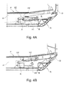
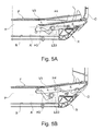
- FIGS. 3A-3B . 4A-4B . 5A-5B such as 6A-6B and 7A-B be different embodiments of adjusting devices with different adjustment V1 to V5 on the basis of in the Figures 1A-1B and 2A-2B illustrated concepts in detail. While in the embodiments of the FIGS. 3A-3B . 4A-4B and 5A-5B a linear adjustment of a Schiebetrittkassette K is provided via the adjustment mechanisms V4 and V5 of the embodiments of Figures 6A-6B and 7A-7B pivoting the Schiebetrittkassette K about the axis of rotation D provided.
- a first (lowest) adjustment position of the sliding step cassette K is illustrated.
- a second (uppermost) end position of the sliding step cassette K is again illustrated.
- an adjustment mechanism V1 is provided with interacting wedge elements K1 and K2 as adjusting elements to adjust the Schiebehoffkassette K as a whole within the cavity H in the shell R of the rail vehicle S.
- the Schiebetrittkassette K is in this case at least two mutually spaced bearing blocks LB1 and LB2 in their Height adjustable.
- Each bearing block LB1, LB2 forms a slotted guide, on which the Schiebelingerkassette K is held displaceably.
- the Schiebelingerkassette K is biased via at least one spring element, preferably via a plurality, each provided on a bearing block LB1, LB2 spring elements, in a (lowermost) adjustment position.
- the (second) wedge element K2 fixedly connected to the sliding step cassette K is also pressed against the (first) wedge element K1 that can be driven by a drive A of the adjusting mechanism V1.
- the two interacting wedge elements K1 and K2 are provided at a distance to the opening O end of the Schiebetrittkassette K.
- the first wedge element K1 can be displaced longitudinally on the bottom B in the direction of the vehicle exterior.
- the second wedging element K2 fixedly connected to the sliding step cassette K then slides along the inclined wedge surface of the first wedge element K1 and is displaced along the wedge surface.
- the associated with the second wedge element K2 Schiebetrittkassette K is mitverlagert and moved due to the positive guidance within the slotted guides of the bearing blocks LB1, LB2 along these slotted guides along linearly upwards in a different adjustment position.
- the wedge member K1 is retracted again, the other wedge member K2 slides down the wedge surface of the first wedge member K1, and the sliding step cassette K is lowered downward.
- the Schiebetrittkassette K does not abut a second wedge element K2 on the wedge surface of the driven first wedge element K1, but to an alternatively ausgestaltetes sliding element or a rotatably mounted rolling element, such. a cylindrical roller.
- FIGS. 4A and 4B is a linear displacement of the Schiebetrittkassette K within the cavity H via an adjustment V2 with a designed as a four-bar linkage lever mechanism realized.
- a drive A which has, for example, a pneumatic cylinder, in this case a first end of a (pivoting) lever H1 is acted upon, which can be pivoted between its two ends is stored.
- the other, second end of this first lever H1 is coupled to another lever H2.
- the second lever H2 is designed to be many times longer than the (pivot) lever H1.
- the further lever H2 of the adjusting V2 is rotatably mounted at its first end within the cavity H and hinged at its other, second end to the Schiebetrittkassette K.
- the lever H1 engages between the two ends of the further lever H2.
- the first lever H1 driven directly by the drive A in a pivoting movement thus acts on the further lever H2 articulated on the sliding step cassette K in such a way that the sliding step cassette K is linearly displaced by the pivoting movements of the individual levers H1, H2.
- the levers H1 and H2 are arranged relative to one another such that the shorter lever H1 in the uppermost adjustment position of the sliding step cassette K is substantially perpendicular to a longitudinal axis of a pneumatic cylinder of the drive A. In this way, the load on the pneumatic cylinder is reduced at least in the uppermost adjustment position of the sliding step cassette K. In addition, acts in this way, the adjustment V2 in this adjustment self-locking and prevents unwanted falling back the Schiebetrittkassette K.
- the adjusting mechanism V3 of the embodiment of the Figs. 5A and 5B also has a lever mechanism with at least two levers H3 and H4.
- the two levers H3 and H4 are each hinged to the Schiebetrittkassette K and on the other hand pivotally mounted on the shell R or within the cavity H.
- a bearing block LB3 is provided on the bottom B of the cavity H, on which this lever H3 is pivotably mounted.
- a lever mechanism provided with only one hinged to the Schiebetrittkassette K lever H5.
- the adjustment mechanism V4 provided here permits a pivoting of the sliding step cassette K about the axis of rotation D.
- the pivoting cassette K at a first end of the lever hinged lever H5 is coupled at its other, second end with a piston element KE of a preferably also pneumatically operating drive A.
- the Schiebetrittkassette K is also designed to be pivotable about a rotation axis D to specify different heights guided therein tread plate in which it can be extended laterally on the rail vehicle S from the opening O.
- the adjustment mechanism V5 of Figs. 7A and 7B in this case has at least one cam element 1.
- This cam element 1 is provided on a drive shaft 2, which is rotatably mounted on a fixed to the bottom B bearing member 3.1.
- the Schiebebergkassette K is present on its underside directly on a cam surface of the cam member 1.
- the position of the Schiebetrittkassette K can be easily changed within the cavity H by rotation of the drive shaft 2.
- a servo motor can be provided for the drive of the drive shaft 2.
- the entire adjustment mechanism V5 thus builds very compact and ensures a high reliability with a small number of adjustable components.
- a cassette holder 5 is provided, to which the Schiebetrittkassette K is mounted and which is mounted adjustably about the axis of rotation D.
- the cross-sectionally L-shaped cassette holder 5 is mounted pivotably on a rear bearing component 3.3, for example in the form of a double bearing.
- the cassette holder 5 forms a preferably welded bearing pin 4a.
- This circular cylindrical bearing journal 4a is rotatably mounted on the rear bearing component 3.3 via a sliding bearing or a rolling bearing.
- the cassette holder 5 is coupled with at least one cam element 1.
- This cam element 1 is connected to a drive shaft 2, which by a drive A to a rotation about its shaft axis can be driven to pivot the cassette holder 5.
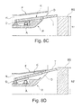
- the height at which the tread plate T is to be extended out of the opening O can be adjusted by pivoting the cassette holder 5 before the tread plate T is extended at standstill of the rail vehicle S.
- Figs. 8C and 8D It is illustrated how the tread plate T in the extended state at platforms BS with different heights h1 and h2 bridges a gap between rail vehicle S and platform BS.
- a certain adjustment of the cassette holder 5 and the Schiebetrittkassette K within the cavity H of the shell R for example, be approached automatically before the rail vehicle S comes to a complete stop. It can be provided that the drive A is controlled via an electronic control system to an adjustment of the cassette holder 5 and in this case a certain adjustment position is approached, which is deposited for the current stop of the rail vehicle S. For example, for the different stations of a rail vehicle S along a predetermined route, the various platform heights can be recorded and stored in a data storage adjustment positions for each station, so that the tread T is automatically extended at the appropriate height on the rail vehicle S.
- sensor elements may be provided on an outer side of the rail vehicle S facing the platform BS in order to detect contactlessly the height of the adjacent platform BS. This automatically determines a suitable adjustment for the cassette holder 5 and the Schiebetrittkassette K and these are taken before or while the tread plate T is extended from the Schiebetrittkassette K.
- a control electronics for the control of the drive A may also be electronically coupled with a position sensor to detect where the rail vehicle S is currently. This can be automatically recognizable and evaluated, which of several (at least two) stored adjustment positions of the cassette holder 5 is to be selected for the next stop of the rail vehicle S.
- a rail vehicle S which has a plurality of adjusting devices, each with an adjustable Schiebetrittkassette K and in which the individual Schiebetrittkassetten K different adjustment positions can be specified.
- the individual cassette holders seen over the entire rail vehicle S drive different adjustment positions to take on each door an individual adjustment position. This is particularly advantageous at platforms where a platform height varies from one end to the other. About the individual adjustment then the appropriate adjustment can be approached on each door for the respective opposite door of the section of the platform.
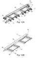
- adjusting device VV shown in perspective has a plurality of cam elements 1 arranged alongside one another along the drive shaft 2, in order to pivot the cassette holder 5 for the sliding step cassette K about the axis of rotation D.
- the cassette holder 5 in this case carries a support of the Schiebetrittkassette K in the form of a frame frame G, on which the tread plate T is guided displaceably via its own adjustment mechanism.
- bearing tray 6 is fixed, used in the preassembled Schiebetrittkassette K as a module and is fixed thereto.
- the cross-sectionally L-shaped cassette holder 5 has a cross member 50 with rear, upstanding support wall and two laterally projecting bearing pins 4a and 4b. These bearing journals 4a and 4b are each rotatably supported via a rear bearing component 3.3 to define the axis of rotation D for the cassette holder 5 and the Schiebetrittkassette K.
- the cassette holder 5 a plurality of substantially perpendicular to the cross member 50 projecting longitudinal beams 51 to 54.
- the longitudinal members are in this case arranged in pairs 51, 52 and 53, 54 parallel to each other and coupled in pairs, each with a cam member 1.
- the total of eight side members 51 to 54 here form a support for in the Figure 15A
- Each four longitudinal members 51 to 54 and thus two pairs of side rails 51, 52 and 53, 54 are each interconnected to increase the rigidity of the cassette holder 5.
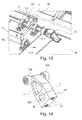
- the individual longitudinal members 51 to 54 are each U-shaped in cross-section and each define a guide for a bearing roller 12a or 12b, which is rotatably mounted on a cam member 1.
- a bearing roller 12a or 12b of a cam element 1 can be mounted on each of the two opposite longitudinal members.
- each cam member 1 is fixed against rotation on the common drive shaft 2.
- the bearing section 10 has a bearing opening 100 which is defined by a clamping part 101 and through which the drive shaft 2 extends in the mounted state.
- the clamp member 101 is fixed to the bearing rollers 12a and 12b supporting portion of the cam member 1 via (cylinder) screws 13 and thus completely removable from the bearing rollers 12a and 12b bearing portion to the cam member 1 in the desired position on the drive shaft 2 position and fix.
- the bearing rollers 12a and 12b bearing portion of the cam member 1 also has a generous recess 11 for weight reduction, which between an upper End of the cam member 1 and the bearing opening 100 is formed for the drive shaft 2.
- a plurality of bearing components 3.1 and 3.2 are fixed to the bottom B of the cavity H.
- inner bearing components 3.2 are provided for the rotatable mounting of the drive shaft 2 and for receiving acting on the cam elements 1 forces.
- the inner bearing components 3.2 lie in an intended mount state of the adjusting device VV below the bearing tray 6 and the Schiebetrittkassette K.
- the drive A for the rotation of the drive shaft 2 is presently arranged at one end of the drive shaft 2.
- the drive A which is in the present case designed in the form of a compact servo motor, drives the drive shaft 2 to rotate and thereby synchronously pivots the rotatably connected to the drive shaft 2 cam elements 1 to act on the cassette holder 5 and to adjust them to a desired adjustment position and thus the tread plate T on the side of the rail vehicle S to specify a certain height in which it is extended from the Schiebetrittkassette K.
- About the drive A can basically the currently occupied adjustment position of the cassette holder 5 and thus the Schiebetrittkassette K are monitored.
- sensor elements may be provided to detect the two possible end positions of the cassette holder 5 and the Schiebetrittkassette K electronically.
- the drive A may also include a motor-gear unit with a relatively small motor, preferably an electric motor, and a transmission.
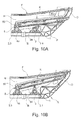
- the Schiebetrittkassette K is a in the Fig. 15B shown assembly / service plate MP on the vehicle floor F accessible.
- the cavity H is accessible from inside the rail vehicle S, and the sliding step cassette K can be removed from the storage tub 6 in which the sliding step cassette K is fixed by a plurality of screws, for example.
- the Schiebebergkassette K can thus be easily replaced and manufactured separately from the adjustment mechanism for height adjustment and later maintained.
- the illustrated embodiment with a modular trained Schiebetrittkassette K and a separate adjustment for the height adjustment of slidably guided in the Schiebetrittkassette K tread plate T can thus be quickly and easily mounted without sacrificing a stable support of the sliding step on the shell R of the rail vehicle S. to have to.
- a drainage pipe is provided at the bottom B, which leads to the outside.
- the drainage pipe is here according to the cross-sectional view of Figures 10A and 10B approximately in the middle between the front and rear row of the bearing components 3.1. 3.2 and 3.3 and arranged below the cassette holder 5.
- About the drainage pipe liquid can flow out of the cavity H and the shell R, which passes through the Schiebetrittkassette K and the bearing trough 6 in the cavity H.
- a designed as a cover 7 multi-part closure element may be provided.
- the cover 7 extends with individual sections 70 and 71 both above and below the Schiebetrittkassette K in the opening O and closes the respective of the Schiebetrittkassette K not covered area of the opening O.
- the two sections 70 and 71 of the cover 7 are here executed in the form of an upper or lower bellows.
- Snow, water, dirt and ice which still passes through the tread plate T in the cavity H, is collected in the storage tub 6 and passed through the shape of the storage tub 6 to the provided on the bottom B drainage pipe and over to the outside.
- the approach of the different possible Ausfahrieren for the tread plate T can be done automatically via a control electronics for the drive A, for example, by the control electronics is coupled to a position sensor, for example, includes a GPS receiver and / or cooperates with a data memory, in which for individual Holding the rail vehicle S records with the respective extension heights are stored.
- a position sensor for example, includes a GPS receiver and / or cooperates with a data memory, in which for individual Holding the rail vehicle S records with the respective extension heights are stored.
- the assumption of a specific adjustment position can be controlled manually, for example via a switch in the driver's cab of the rail vehicle.
Landscapes
- Engineering & Computer Science (AREA)
- Mechanical Engineering (AREA)
- Life Sciences & Earth Sciences (AREA)
- Wood Science & Technology (AREA)
- Vehicle Body Suspensions (AREA)
Applications Claiming Priority (1)
| Application Number | Priority Date | Filing Date | Title |
|---|---|---|---|
| DE102014207349.9A DE102014207349B4 (de) | 2014-04-16 | 2014-04-16 | Verstellvorrichtung zur Höheneinstellung eines an einem Fahrzeug ausfahrbaren Trittelements |
Publications (1)
| Publication Number | Publication Date |
|---|---|
| EP2933167A1 true EP2933167A1 (fr) | 2015-10-21 |
Family
ID=53002510
Family Applications (1)
| Application Number | Title | Priority Date | Filing Date |
|---|---|---|---|
| EP15163712.1A Withdrawn EP2933167A1 (fr) | 2014-04-16 | 2015-04-15 | Dispositif de réglage destiné à régler la hauteur d'un marchepied déployable sur un véhicule |
Country Status (2)
| Country | Link |
|---|---|
| EP (1) | EP2933167A1 (fr) |
| DE (1) | DE102014207349B4 (fr) |
Cited By (7)
| Publication number | Priority date | Publication date | Assignee | Title |
|---|---|---|---|---|
| EP3081450A1 (fr) * | 2015-04-15 | 2016-10-19 | Bombardier Transportation GmbH | Véhicule de transport |
| AT519944A1 (de) * | 2017-05-11 | 2018-11-15 | Siemens Ag Oesterreich | Spaltüberbrückung |
| CN111376936A (zh) * | 2020-04-27 | 2020-07-07 | 中车青岛四方机车车辆股份有限公司 | 门间隙补偿器及轨道车辆 |
| US20210394803A1 (en) * | 2020-06-22 | 2021-12-23 | Stadler Rail Ag | Rail vehicle car for transporting passengers, rail vehicle with a rail vehicle car and method for forming a transition between rail vehicle cars |
| KR20230102157A (ko) * | 2021-12-30 | 2023-07-07 | 현대로템 주식회사 | 철도차량용 승하차 발판 제어방법 |
| WO2024077978A1 (fr) * | 2022-10-14 | 2024-04-18 | 仝达产品开发(惠州)有限公司 | Marche de véhicule |
| CN119928927A (zh) * | 2025-02-21 | 2025-05-06 | 中车株洲电力机车有限公司 | 一种轨道车辆车门处地板调节装置及调节方法 |
Families Citing this family (3)
| Publication number | Priority date | Publication date | Assignee | Title |
|---|---|---|---|---|
| DE102016103265A1 (de) * | 2016-02-24 | 2017-08-24 | Bombardier Transportation Gmbh | Trittvorrichtung für ein Fahrzeug und Verfahren zum Betrieb dafür |
| AT519948B1 (de) * | 2017-04-24 | 2020-04-15 | Siemens Mobility Austria Gmbh | Spaltüberbrückung und Verfahren zum Betrieb einer Spaltüberbrückung |
| FR3101314B1 (fr) * | 2019-09-30 | 2022-05-13 | Faiveley Transp Tours | Ensemble de marchepied pour véhicule de transport, véhicule ainsi équipé et procédé de mise en œuvre de ce véhicule |
Citations (9)
| Publication number | Priority date | Publication date | Assignee | Title |
|---|---|---|---|---|
| US3672311A (en) * | 1968-10-23 | 1972-06-27 | Linke Hofmann Busch | Movable stair mounting arrangement for vehicles |
| FR2405849A1 (fr) * | 1977-10-13 | 1979-05-11 | Faiveley Sa | Marchepied escamotable, notamment pour une porte de voiture de chemins de fer |
| EP0217265A1 (fr) * | 1985-09-25 | 1987-04-08 | Gec Alsthom Sa | Dispositif permettant un acces aisé aux véhicules ferroviaires lors des arrêts en station |
| EP0345706A1 (fr) * | 1988-06-08 | 1989-12-13 | Gec Alsthom Sa | Emmarchement à marches escamotables pour porte d'accès à un véhicule ferroviaire de transport de voyageurs |
| EP0348928A1 (fr) * | 1988-07-01 | 1990-01-03 | Gec Alsthom Sa | Emmarchement à marches escamotables pour porte d'accès et de sortie d'un véhicule ferroviaire de transport de voyageurs |
| DE19531284A1 (de) * | 1995-08-25 | 1997-02-27 | Abb Patent Gmbh | Schienenfahrzeug für den Personenverkehr |
| DE20104221U1 (de) * | 2001-03-09 | 2001-07-19 | Schliess- und Sicherungssysteme GmbH, 99974 Mühlhausen | Einstieg für Schienenfahrzeuge |
| EP1808352B1 (fr) | 2006-01-12 | 2009-03-11 | Siemens Aktiengesellschaft | Véhicule ferroviaire ayant au moins une zone de l'accès et une construction de plancher modulaire |
| EP2103498A1 (fr) * | 2008-03-20 | 2009-09-23 | ALSTOM Transport SA | Véhicule ferroviaire à plate-forme et marchepied mobiles |
Family Cites Families (3)
| Publication number | Priority date | Publication date | Assignee | Title |
|---|---|---|---|---|
| GB9818781D0 (en) * | 1998-08-28 | 1998-10-21 | Passenger Lift Serv Ltd | Access ramp |
| DE102012204304A1 (de) * | 2012-03-19 | 2013-09-19 | Siemens Aktiengesellschaft | Schienenfahrzeug mit einem für Personen mit reduzierter Mobilität ausgelegten Personeneinstieg |
| FR3003529B1 (fr) | 2013-03-22 | 2015-04-17 | Alstom Transport Sa | Voiture de vehicule ferroviaire comprenant un systeme d'acces |
-
2014
- 2014-04-16 DE DE102014207349.9A patent/DE102014207349B4/de active Active
-
2015
- 2015-04-15 EP EP15163712.1A patent/EP2933167A1/fr not_active Withdrawn
Patent Citations (9)
| Publication number | Priority date | Publication date | Assignee | Title |
|---|---|---|---|---|
| US3672311A (en) * | 1968-10-23 | 1972-06-27 | Linke Hofmann Busch | Movable stair mounting arrangement for vehicles |
| FR2405849A1 (fr) * | 1977-10-13 | 1979-05-11 | Faiveley Sa | Marchepied escamotable, notamment pour une porte de voiture de chemins de fer |
| EP0217265A1 (fr) * | 1985-09-25 | 1987-04-08 | Gec Alsthom Sa | Dispositif permettant un acces aisé aux véhicules ferroviaires lors des arrêts en station |
| EP0345706A1 (fr) * | 1988-06-08 | 1989-12-13 | Gec Alsthom Sa | Emmarchement à marches escamotables pour porte d'accès à un véhicule ferroviaire de transport de voyageurs |
| EP0348928A1 (fr) * | 1988-07-01 | 1990-01-03 | Gec Alsthom Sa | Emmarchement à marches escamotables pour porte d'accès et de sortie d'un véhicule ferroviaire de transport de voyageurs |
| DE19531284A1 (de) * | 1995-08-25 | 1997-02-27 | Abb Patent Gmbh | Schienenfahrzeug für den Personenverkehr |
| DE20104221U1 (de) * | 2001-03-09 | 2001-07-19 | Schliess- und Sicherungssysteme GmbH, 99974 Mühlhausen | Einstieg für Schienenfahrzeuge |
| EP1808352B1 (fr) | 2006-01-12 | 2009-03-11 | Siemens Aktiengesellschaft | Véhicule ferroviaire ayant au moins une zone de l'accès et une construction de plancher modulaire |
| EP2103498A1 (fr) * | 2008-03-20 | 2009-09-23 | ALSTOM Transport SA | Véhicule ferroviaire à plate-forme et marchepied mobiles |
Cited By (10)
| Publication number | Priority date | Publication date | Assignee | Title |
|---|---|---|---|---|
| EP3081450A1 (fr) * | 2015-04-15 | 2016-10-19 | Bombardier Transportation GmbH | Véhicule de transport |
| AT519944A1 (de) * | 2017-05-11 | 2018-11-15 | Siemens Ag Oesterreich | Spaltüberbrückung |
| AT519944B1 (de) * | 2017-05-11 | 2019-02-15 | Siemens Ag Oesterreich | Spaltüberbrückung |
| CN111376936A (zh) * | 2020-04-27 | 2020-07-07 | 中车青岛四方机车车辆股份有限公司 | 门间隙补偿器及轨道车辆 |
| US20210394803A1 (en) * | 2020-06-22 | 2021-12-23 | Stadler Rail Ag | Rail vehicle car for transporting passengers, rail vehicle with a rail vehicle car and method for forming a transition between rail vehicle cars |
| US11970193B2 (en) * | 2020-06-22 | 2024-04-30 | Stadler Rail Ag | Rail vehicle car for transporting passengers, rail vehicle with a rail vehicle car and method for forming a transition between rail vehicle cars |
| KR20230102157A (ko) * | 2021-12-30 | 2023-07-07 | 현대로템 주식회사 | 철도차량용 승하차 발판 제어방법 |
| WO2024077978A1 (fr) * | 2022-10-14 | 2024-04-18 | 仝达产品开发(惠州)有限公司 | Marche de véhicule |
| CN119928927A (zh) * | 2025-02-21 | 2025-05-06 | 中车株洲电力机车有限公司 | 一种轨道车辆车门处地板调节装置及调节方法 |
| CN119928927B (zh) * | 2025-02-21 | 2025-10-17 | 中车株洲电力机车有限公司 | 一种轨道车辆车门处地板调节装置及调节方法 |
Also Published As
| Publication number | Publication date |
|---|---|
| DE102014207349B4 (de) | 2022-01-13 |
| DE102014207349A1 (de) | 2015-10-22 |
Similar Documents
| Publication | Publication Date | Title |
|---|---|---|
| DE102014207349B4 (de) | Verstellvorrichtung zur Höheneinstellung eines an einem Fahrzeug ausfahrbaren Trittelements | |
| EP3237254B1 (fr) | Marchepied avec fonction de levage et de rampe | |
| DE2946531C2 (de) | Mehrstufiger, seitlich ausfahrbarer Einstieg für Fahrzeuge für den Personenverkehr, insbesondere Omnibusse | |
| EP2297018B1 (fr) | Système de porte d'ascenseur à dispositif de verrouillage de porte de cabine | |
| EP3052728B1 (fr) | Système de porte coulissante pour une ouverture de porte latérale d'une voiture particulière ; voiture particulière comprenant un système de porte coulissante | |
| EP3007953A1 (fr) | Paroi de protection pour la protection de personnes de véhicules ferroviaires en circulation | |
| EP2862757B1 (fr) | Dispositif de réglage d'un volet avant et véhicule automobile associé | |
| EP0641701B1 (fr) | Marchepieds pour véhicules ferroviaires | |
| EP3121086B1 (fr) | Vehicule ferroviaire, comprenant un element de pont destine a former un pont entre une porte et un quai | |
| EP3663158B1 (fr) | Porte coulissante à basculement avec système de marche pour un véhicule | |
| EP3507161B1 (fr) | Dispositif permettant de rendre étanche au moins un vantail de porte d'un véhicule ferroviaire et véhicule ferroviaire | |
| EP2165868B1 (fr) | Système de porte coulissante pivotante | |
| WO2013164056A1 (fr) | Mécanisme de réglage d'un élément de carrosserie | |
| DE202016101709U1 (de) | Schwenkschiebetür | |
| EP2354415B1 (fr) | Porte sectionnelle | |
| DE102014010488A1 (de) | Heckrotorfräse mit bewegbarem Aufstieg | |
| WO2013164057A1 (fr) | Toit ouvrant de véhicule pourvu d'un dispositif de collecte d'eau | |
| AT501549B1 (de) | Trittstufenantrieb | |
| EP1354759A1 (fr) | Plateau de chargement extensible | |
| DE102015213651B4 (de) | Schienenfahrzeug mit Brückenelement zur Spaltüberbrückung zwischen einer Tür und einem Bahnsteig | |
| WO2013164058A1 (fr) | Ensemble cadre d'un toit ouvrant de véhicule automobile | |
| WO2018197161A1 (fr) | Système de franchissement d'espace et procédé servant à faire fonctionner un système de franchissement d'espace | |
| DE102015122423A1 (de) | Stromabnehmersystem für ein längs einer Stromschienenanordnung verfahrbares Fahrzeug | |
| WO2013164059A1 (fr) | Volet d'un toit ouvrant de véhicule automobile | |
| EP2226208B1 (fr) | Dispositif de porte coulissante pour véhicule automobile |
Legal Events
| Date | Code | Title | Description |
|---|---|---|---|
| PUAI | Public reference made under article 153(3) epc to a published international application that has entered the european phase |
Free format text: ORIGINAL CODE: 0009012 |
|
| AK | Designated contracting states |
Kind code of ref document: A1 Designated state(s): AL AT BE BG CH CY CZ DE DK EE ES FI FR GB GR HR HU IE IS IT LI LT LU LV MC MK MT NL NO PL PT RO RS SE SI SK SM TR |
|
| AX | Request for extension of the european patent |
Extension state: BA ME |
|
| STAA | Information on the status of an ep patent application or granted ep patent |
Free format text: STATUS: THE APPLICATION IS DEEMED TO BE WITHDRAWN |
|
| 18D | Application deemed to be withdrawn |
Effective date: 20160422 |