EP2933176B1 - Élément de planche à roulettes et planche à roulettes comprenant celui-ci - Google Patents
Élément de planche à roulettes et planche à roulettes comprenant celui-ci Download PDFInfo
- Publication number
- EP2933176B1 EP2933176B1 EP13870536.3A EP13870536A EP2933176B1 EP 2933176 B1 EP2933176 B1 EP 2933176B1 EP 13870536 A EP13870536 A EP 13870536A EP 2933176 B1 EP2933176 B1 EP 2933176B1
- Authority
- EP
- European Patent Office
- Prior art keywords
- hole
- pivot
- skateboard
- truck
- retaining member
- Prior art date
- Legal status (The legal status is an assumption and is not a legal conclusion. Google has not performed a legal analysis and makes no representation as to the accuracy of the status listed.)
- Not-in-force
Links
Images


Classifications
-
- A—HUMAN NECESSITIES
- A63—SPORTS; GAMES; AMUSEMENTS
- A63C—SKATES; SKIS; ROLLER SKATES; DESIGN OR LAYOUT OF COURTS, RINKS OR THE LIKE
- A63C17/00—Roller skates; Skate-boards
- A63C17/0046—Roller skates; Skate-boards with shock absorption or suspension system
-
- B—PERFORMING OPERATIONS; TRANSPORTING
- B62—LAND VEHICLES FOR TRAVELLING OTHERWISE THAN ON RAILS
- B62M—RIDER PROPULSION OF WHEELED VEHICLES OR SLEDGES; POWERED PROPULSION OF SLEDGES OR SINGLE-TRACK CYCLES; TRANSMISSIONS SPECIALLY ADAPTED FOR SUCH VEHICLES
- B62M1/00—Rider propulsion of wheeled vehicles
-
- A—HUMAN NECESSITIES
- A63—SPORTS; GAMES; AMUSEMENTS
- A63C—SKATES; SKIS; ROLLER SKATES; DESIGN OR LAYOUT OF COURTS, RINKS OR THE LIKE
- A63C17/00—Roller skates; Skate-boards
- A63C17/0093—Mechanisms transforming leaning into steering through an inclined geometrical axis, e.g. truck
-
- A—HUMAN NECESSITIES
- A63—SPORTS; GAMES; AMUSEMENTS
- A63C—SKATES; SKIS; ROLLER SKATES; DESIGN OR LAYOUT OF COURTS, RINKS OR THE LIKE
- A63C17/00—Roller skates; Skate-boards
- A63C17/01—Skateboards
- A63C17/014—Wheel arrangements
-
- A—HUMAN NECESSITIES
- A63—SPORTS; GAMES; AMUSEMENTS
- A63C—SKATES; SKIS; ROLLER SKATES; DESIGN OR LAYOUT OF COURTS, RINKS OR THE LIKE
- A63C17/00—Roller skates; Skate-boards
- A63C17/01—Skateboards
- A63C17/011—Skateboards with steering mechanisms
- A63C17/012—Skateboards with steering mechanisms with a truck, i.e. with steering mechanism comprising an inclined geometrical axis to convert lateral tilting of the board in steering of the wheel axis
Definitions
- the invention relates to skateboard assembly and skateboard having the same.
- the conventional skateboard is composed of a deck, a baseplate, trucks having through holes, kingpins passing through the through holes of the trucks so as to fix the trucks to the baseplate, buffering members each provided between the kingpin and the through hole, and wheels rotatably connected to ends of the two trucks.
- the conventional skateboard is designed to slide on even roadways. While the provision of the buffering members facilitates veer of the skateboard, they cannot help skateboard to slide on uneven roadways, not to mention stairs.
- WO0220100A1 discloses a prior art skateboard. Further prior art skateboards are disclose in the documents FR2810894A1 , WO03064241A1 , US4337961A1 , US4062557A1 , US6158753A1 , FR2763002A1 , and DE29509197U1 .
- the present invention provides a skateboard assembly comprising: a truck, including a pivot that has two oppositely extending axial sections; and a frame, including a pivot hole, and a first segment and a second segment extending at two sides of the pivot hole, wherein the first segment and the second segment include an angle and each of the first and second segments has an end far from the pivot hole provided with an axle; wherein the pivot of the truck has two first retaining members each deposited between a middle part and an end of the pivot, and the frame has a first positioning portion provided on a side thereof which faces the truck and on which the pivot hole is provided, and wherein the skateboard assembly further comprises two second retaining members each having a second positioning portion and a fifth through hole, the second positioning portion is engaged with the first positioning portion, and when the pivot passes through the fifth through hole and the pivot hole, the second retaining member moves with the frame, so that contact between the first retaining member and the second retaining member defines a moving range of the frame
- the skateboard assembly further comprising wheels each rotatably mounted around the axle of the first segment and of the second segment.
- the truck further comprises a first through hole
- the skateboard assembly further comprises: a baseplate that includes a first mounting hole; a kingpin that extends from one side of the baseplate; and a first fastening member, wherein, the kingpin passes through the first through hole and gets engaged with the first fastening member so as to fixedly combine the truck with the baseplate.
- the skateboard assembly further comprising a first buffering member, which is mounted around the kingpin, wherein the kingpin has a sectional area smaller than a diameter of the first through hole, and the first buffering member is at least partially received in a gap formed between the kingpin and the first through hole.
- the skateboard assembly further comprising: a jointing member, including a second through hole and a third through hole, wherein the second through hole is parallel to the first through hole, and the third through hole is far from one end of the second through hole; a keel, having a fourth through hole parallel to the third through hole; and a second fastening member, wherein, the kingpin passes through the first through hole and the second through hole, and the jointing member is fixed to the truck through the first fastening member, and wherein the second fastening member passes through the third through hole and the fourth through hole, so as to affix the keel to the truck through the jointing member.
- a jointing member including a second through hole and a third through hole, wherein the second through hole is parallel to the first through hole, and the third through hole is far from one end of the second through hole
- a keel having a fourth through hole parallel to the third through hole
- a second fastening member wherein, the kingpin passes through the first through
- the third through hole has a diameter greater than a sectional area of the second fastening member.
- the third through hole has a middle part defined by two flat walls that are parallel to each other and separated by a distance equal to or slightly greater than a width of the sectional area of the second fastening member, and the third through hole extends toward two sides to form round-arced walls.
- the keel includes at least two lengthwise plates, and each said lengthwise plate has each of two ends thereof formed with the fourth through hole, and the fourth through holes of the two lengthwise plates are provides on two sides of the corresponding third through hole, respectively.
- the first retaining member has a ramp provides on a side thereof facing the frame
- the second retaining member has a ramp provides on a side thereof facing the first retaining member and being parallel to the ramp of the first retaining member
- the second retaining member is made of nylon.
- the pivot of the truck has two first retaining members each deposited between a middle part and an end of the pivot
- the frame has a third retaining member provided on a side thereof which faces the truck and on which the pivot hole is provided, so that when the pivot passes through the pivot hole, contact between the first retaining member and the third retaining member defines a moving range of the frame.
- the skateboard assembly further comprises a second buffering member, which is deposited between the first retaining member and the second retaining member.
- the first segment or the second segment of the frame has a cutout portion.
- the present invention further provides a skateboard comprising: a truck, including a first through hole, and a pivot that has two oppositely extending axial sections; a frame, including a pivot hole, and a first segment and a second segment extending at two sides of the pivot hole, wherein the first segment and the second segment include an angle such that each frame forms an included angle that is smaller than 180 degrees, and each of the first and second segments has an end far from the pivot hole provided with an axle; wheels, each pivotably mounted around the axle of the first segment and of the second segment; a baseplate that includes a first mounting hole; a kingpin that extends from one side of the baseplate; a first buffering member, which is mounted around the kingpin, wherein the kingpin has a sectional area smaller than a diameter of the first through hole, and the first buffering member is at least partially received in a gap formed between the kingpin and the first through hole; a first fastening member; a second fastening member; a deck, including a second mounting
- the pivot of the truck has two first retaining members each deposited between a middle part and an end of the pivot
- the frame has a first positioning portion provided on a side thereof which faces the truck and on which the pivot hole is provided
- the skateboard assembly further comprises two second retaining members each having a second positioning portion and a fifth through hole, so that the second positioning portion is engaged with the first positioning portion, and when the pivot passes through the fifth through hole and the pivot hole, the second retaining member moves with the frame, so that contact between the first retaining member and the second retaining member defines a moving range of the frame.
- the first retaining member has a ramp formed on a side thereof facing the frame
- the second retaining member has a ramp formed on a side thereof facing the first retaining member and being parallel to the ramp of the first retaining member
- the pivot of the truck has two first retaining members each deposited between a middle part and an end of the pivot
- the frame has a third retaining member provided on a side thereof which faces the truck and on which the pivot hole is provided, so that when the pivot passes through the pivot hole, contact between the first retaining member and the third retaining member defines a moving range of the frame.
- the skateboard further comprises a second buffering member, which is deposited between the first retaining member and the second retaining member.
- the first segment or the second segment of the frame has a cutout portion.
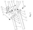
- a skateboard assembly comprises a truck 10 and a frame 11.
- the truck 10 includes a pivot 101 that has a first axial section 1011 and a second axial section 1012 extending oppositely.
- the first axial section 1011 and the second axial section 1012 each have a retaining member 103.
- the retaining member 103 is configured to limit the rotating range of the frame 11 about the truck 10.
- the frame 11 includes a pivot hole 111.
- the pivot hole 111 is preferably located in the middle part of the frame 11, but can be located alternatively on different sites in the frame 11 as required.
- the frame 11 has a first segment 112 and a second segment 113 extending at two sides of the pivot hole 111.
- the first segment 112 and the second segment 113 include an angle.
- the frame 11 forms an included angle that is smaller than 180 degrees, such as an included angle of 170 degrees or 160 degrees, and faces the ground on which the wheel is placed, so that the frame 11 is V-shaped.
- the first segment 112 and the second segment 113 each have their ends far from the pivot hole 111 provided with a first axle 1121 or a second axle 1131.
- Each of the first axle 1121 and the second axle 1131 is configured to receive a wheel rotating thereabout.
- the first axial section 1011 and the second axial section 1012 may have their outer ends threaded.
- the frames 11 are mounted around the first axial section 1011 and the second axial section 1012 of the truck 10 through their pivot holes 111, and pivotally retained on the truck 10 from detachment by means of, for example, a combination of a rubber-made elastic member 201, a wash 202 and a nut 203.
- the truck 10 and the frame 11 may be made of metal, such as aluminum or stainless steel. Alternatively, they can be made of fiberglass or nylon.
- the first segment 112 and/or the second segment 113 of the frame 11 may optionally include a cutout portion 1122 and/or 1132. By hollowing out the first segment 112 and/or the second segment 113, the frame 11 and therefore the whole skateboard are lightened.
- the skateboard typically uses two tandem arranged trucks 10, and each of the trucks 10 has its first and second axial sections 1011, 1012 pivotally connected to two frames 11, respectively. It is to be noted that for the sake of illustrative clarity, the following description is directed to the components and configuration of one of these frame 11 only.
- the frames 11 can adapt the skateboard to the uneven roadway, and reduce vibration, thereby ensuring the skateboard to move smoothly.
- each said truck 10 there may be a baseplate 12, a kingpin 13, a fastening member 14 and a buffering member 15 provided.
- the truck 10 may further include a through hole 102.
- the kingpin 13 passes through the through hole 102 and then gets engaged with the fastening member 14 so as to fix the truck 10 to the baseplate 12.
- the baseplate 12 is formed with a plurality of through holes 121, through which fasteners, such as screws, can pass so as to fix the baseplate 12 together with the truck 10 and the frames 11 to the deck of the skateboard.
- the buffering member 15 is received in the through hole 102 and mounted around the kingpin 13.
- the kingpin 13 has a sectional area smaller than a diameter of the through hole 102, and the buffering member 15 has at least a part received in a gap formed between the kingpin 13 and the through hole 102.
- the buffering member 15 located between the kingpin 13 and the through hole 102 may be made of, for example, rubber and is designed for allowing that when the user applies a relatively large force at either side of the skateboard, the skateboard together with the baseplate 12 and the kingpin 13 affixed thereto can lean toward the force-receiving side, thereby cause the skateboard to veer.
- the disclosed skateboard assembly may optionally include a jointing member 16, a keel 17 and fastening members 181, 182.
- the jointing member 16 comprises a through hole 161 and another through hole 162.
- the through hole 161 is parallel to the through hole 102 of the truck 10, and the through hole 162 is located at the end of the jointing member 16 far from the through hole 161.
- the through hole 162 and the through hole 161 may be such formed that they extends orthogonally.
- through hole 161 is perpendicular to the axis of the truck 10, while the through hole 162 is parallel to the axis of the truck 10.
- the keel 17 has a through hole 171 parallel to the through hole 162. It is to be noted that, in the present embodiment, two said trucks 10, two said jointing members 16 and two said keel 17 are provided for the two tandem trucks 10 and their frames 11.
- the two jointing members 16 are such arranged that their ends having the through holes 162 face each other under the skateboard.
- each skateboard has two keels 17 flanking the two jointing members 16.
- Each of the keels 17 has its two ends formed with through holes 171 aligned with the two through holes 162 of the tandem jointing members 16.
- the keel 171 is preferably in the form of a lengthwise plate.
- the fastening members include a screw 181 and a nut 182, wherein the screw 181 passes through the through holes 171 of the two keels 17 and four through holes 171 formed in four washes 301 that come in pairs to flank the keels 17, and then gets engaged with the nut 182, so as to combine the keels 17 with the jointing member 16 and attach the keels 17 to the truck 10 through the jointing member 16.
- the through hole 162 has a diameter greater than a sectional area of the screw 181, so that the through hole 162 receives and allows the screw 181 to move therein. More preferably, as shown in FIG. 2 , the through hole 162 has its middle part defined by two flat walls that are parallel to each other and separated by a distance equal to or slightly greater than a width of the sectional area of the screw 181, with two ends of the through hole 162 each defined by an arc.
- the jointing members 16 and the keels 17 may be made of nylon.
- the keels 17 are designed to directly contact nosing or convexity when the user skateboards along stairs or on uneven roadways, and support the skateboard, so as to prevent the deck of the skateboard directly contacting the nosing or convexity.
- the contacting area between the keels 17 and stair nosing is far smaller than the contacting area that otherwise would be formed between the deck and the stair nosing, the keels 17 are helpful to ensure smooth slide of the skateboard along stairs.
- the through hole 162 is designed to be larger than the fastening member (i.e. the screw 181) for providing extra space to offset the external force applied to the keels 17 that are contacting stair nosing.
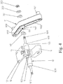
- each of the first and second axial sections 1011, 1012 of pivot 101 on the truck 10 is provided with a retaining member 103.
- the retaining member 103 is deposited between the middle part and the end of the pivot 101.
- at the side of the frame 11 that faces the truck 10 and includes the pivot hole 111 there is a positioning portion 114 provided.
- the disclosed skateboard assembly further comprises retaining members 19 each located between one said the retaining member 103 and one said frame 11.
- the retaining member 19 has a positioning portion 191 and a through hole 192.
- the positioning portion 191 is configured to engage with the positioning portion 114.
- the pivot 101 passing through the through hole 192 and the pivot hole 111 makes the retaining member 19 and the frame 11 move in a mutually connected manner. Furthermore, the contact between the retaining member 103 and the retaining member 19 limits the moving range of the frame 11.
- the retaining member 103 has a ramp 1031 facing the frame 11, while the retaining member 19 has a ramp 193 facing the retaining member 103 and parallel to the ramp 1031 of the retaining member 103.
- the retaining member 19 may be made of nylon. With the combination between the retaining member 19 and the frame 11, and the combination between the parallel ramps 1031, 193 of the retaining member 103 and the retaining member 19, when the skateboard moves on an uneven roadway or along stairs, the nylon-made retaining member 19 can restrict the frame 11 to swing within a certain range, thereby maintaining the steady contact between the skateboard wheels and the ground or stairs.
- a member like the ramp 193 of the retaining member 19 may be integratedly formed at the side of the frame 11 that faces the retaining member 103 of the truck 10 and has the pivot hole 111.
- a buffering member 40 made of nylon or made of rubber is deposited between the retaining member 103 and the ramp 193.
- FIG. 5 a schematic drawing shows structure of the disclosed assembly as described in the mentioned embodiments. As shown, after the skateboard assembly is assembled, wheels 50 can be mounted on the first axles 1121 and the second axles 1131 on the frames 11 attached to the two tandem trucks 10.
- FIG. 6 a schematic drawing shows a skateboard using the disclosed assemblies.
- a deck 60 including a plurality of mounting holes 601.
- the plurality of mounting holes 601 are at least partially correspond to the plurality of through holes 121.
- the assembled structure of the present invention as shown in FIG. 5 can then be fixed to the deck 60 to form the skateboard of the present invention.
Landscapes
- Engineering & Computer Science (AREA)
- Chemical & Material Sciences (AREA)
- Combustion & Propulsion (AREA)
- Transportation (AREA)
- Mechanical Engineering (AREA)
- Motorcycle And Bicycle Frame (AREA)
Claims (17)
- Ensemble de planche à roulettes comprenant :un truck (10) comprenant un pivot (101) qui a deux sections axiales s'étendant de manière opposée (1011, 1012) ; etdeux cadres (11), chacun des cadres (11) comprenant un orifice de pivot (111) et un premier segment (112) et un second segment (113) s'étendant au niveau de deux côtés de l'orifice de pivot (111), le premier segment (112) et le second segment (113) comprenant un angle tel que chaque cadre (11) forme un angle inclus qui est inférieur à 180 degrés et chacun des premier et second segments (112, 113) a une extrémité séparée de l'orifice de pivot (111) pourvue d'un essieu (1121, 1131) ;caractérisé en ce quele pivot (101) du truck (10) a deux premiers éléments de retenue (103) chacun étant déposé entre une partie intermédiaire et une extrémité du pivot (101), et le cadre (11) a une première partie de positionnement (114) disposée sur un côté de celui-ci qui fait face au truck (10) et sur lequel l'orifice de pivot (111) est disposé, et dans lequel l'ensemble de planche à roulettes comprend en outre deux seconds éléments de retenue (19) ayant chacun une seconde partie de positionnement (191) et un cinquième trou traversant (192), la seconde partie de positionnement (191) étant en prise avec la première partie de positionnement (114), et lorsque le pivot (101) passe à travers le cinquième trou traversant (192) et l'orifice de pivot (111), le second élément de retenue (19) se déplace avec le cadre (11), de telle sorte qu'un contact entre le premier élément de retenue (103) et le second élément de retenue (19) définit une plage de déplacement du cadre (11).
- Ensemble de planche à roulettes selon la revendication 1, comprenant en outre des roues (50) montées chacune de manière pivotante autour de l'essieu (1121, 1131) du premier segment (112) et du second segment (113).
- Ensemble de planche à roulettes selon la revendication 1, dans lequel le truck (10) comprend en outre un premier trou traversant (102) et l'ensemble de planche à roulettes comprend en outre :une plaque de base (12) qui comprend un premier orifice de montage (121) ;un pivot central (13) qui s'étend à partir d'un côté de la plaque de base (12) ; etun premier élément de fixation (14),dans lequel le pivot central (13) passe à travers le premier trou traversant (102) et vient en prise avec le truck (10) avec la plaque de base (12) à travers le premier élément de fixation (14).
- Ensemble de planche à roulettes selon la revendication 3, comprenant en outre un premier élément tampon (15), qui est monté autour du pivot central (13), le pivot central (13) ayant une zone transversale inférieure à un diamètre du premier trou traversant (102), et le premier élément tampon (15) est au moins en partie reçu dans un jeu formé entre le pivot central (13) et le premier trou traversant (102).
- Ensemble de planche à roulettes selon la revendication 4, comprenant en outre :un élément de jonction (16) comprenant un deuxième trou traversant (161) et un troisième trou traversant (162), le deuxième trou traversant (161) étant parallèle au premier trou traversant (102) et le troisième trou traversant (162) est séparé d'une extrémité du deuxième trou traversant (161) ;une quille (17) ayant un quatrième trou traversant (171) parallèle au troisième trou traversant (162) ; etun deuxième élément de fixation (181),dans lequel, le pivot central (13) passe à travers le premier trou traversant (102) et le deuxième trou traversant (161), et l'élément de jonction (16) est fixé au truck (10) à travers le premier élément de fixation (14), et dans lequel le deuxième élément de fixation (181) passe à travers le troisième trou traversant (162) et le quatrième trou traversant (171), de façon à apposer la quille (17) au truck (10) à travers l'élément de jonction (16).
- Ensemble de planche à roulettes selon la revendication 5, dans lequel le troisième trou traversant (162) a un diamètre supérieur à une zone transversale du deuxième élément de fixation (181).
- Ensemble de planche à roulettes selon la revendication 6, dans lequel des parois plates d'une partie intermédiaire du troisième trou traversant (162) sont parallèles les unes aux autres et séparées par une distance égale ou légèrement supérieure à une largeur de la zone transversale du deuxième élément de fixation (181), et le troisième trou traversant (162) s'étend vers deux côtés pour former des parois arquées- arrondies.
- Ensemble de planche à roulettes selon la revendication 5, dans lequel la quille (17) comprend au moins deux plaques longitudinales, chacune d'entre elles ayant les quatrièmes trous traversants (171) formés sur deux extrémités de celles-ci, et les quatrièmes trou traversants (171) de chacune des plaques longitudinales sont disposés sur deux côtés du troisième trou traversant correspondant (162), respectivement.
- Ensemble de planche à roulettes selon la revendication 1, dans lequel le premier élément de retenue (103) est formé avec une rampe (1031) disposée sur un côté de celui-ci faisant face au cadre (11), et le second élément de retenue (19) a une rampe (193) disposée sur un côté de celui-ci faisant face au premier élément de retenue (103) et étant parallèle à la rampe (1031) du premier élément de retenue (103).
- Ensemble de planche à roulettes selon la revendication 1, dans lequel le second élément de retenue (19) est réalisé à partir de nylon.
- Ensemble de planche à roulettes selon la revendication 1, dans lequel le premier segment (112) ou le second segment (113) du cadre (11) a une partie en découpe (1122, 1132).
- Planche à roulettes comprenant :un ensemble de planche à roulettes selon la revendication 1 ;le truck (10), comprenant un premier trou traversant (102) ;des roues (50), chacune étant montée de manière pivotante autour de l'essieu (1121, 1131) du premier segment (112) et du second segment (113) ;une plaque de base (12) qui comprend un premier orifice de montage (121) ;un pivot principal (13) qui s'étend à partir d'un côté de la plaque de base (12) ;un premier élément tampon (15), lequel est monté autour du pivot principal (13), le pivot principal (13) ayant une zone transversale inférieure à un diamètre du premier trou traversant (102) et le premier élément tampon (102) est au moins en partie reçu dans un jeu formé entre le pivot principal (13) et le premier trou traversant (102) ;un premier élément de fixation (14) ;un deuxième élément de fixation ;une plateforme (60), comprenant un second trou de montage (601) correspondant au premier trou de montage (121) ;un élément de jonction (16) comprenant un deuxième trou traversant (161) et un troisième trou traversant (162), dans laquelle le deuxième trou traversant (161) est parallèle au premier trou traversant (102), et le troisième trou traversant (162) est espacé d'une extrémité du deuxième trou traversant (161) ;une quille (17) ayant un quatrième trou traversant (171) parallèle au troisième trou traversant (162) ; etun troisième élément de fixation (181),dans laquelle le pivot central (13) passe à travers le premier trou traversant (102) et le deuxième trou traversant (161) et vient en prise avec le premier élément de fixation (14) de façon à combiner fixement le truck (10) à la plaque de base (12), et le troisième élément de fixation passe à travers le premier trou de montage (121) et le deuxième trou de montage correspondant (601), de façon à combiner fixement la plaque de base (12) à la plateforme (60),dans laquelle l'élément de jonction (16) est fixé au truck (10) par l'intermédiaire du premier élément de fixation (14) et dans laquelle le deuxième élément de fixation (181) passe à travers le troisième trou traversant (161) et le quatrième trou traversant (171) de façon à apposer la quille (17) au truck (10) à travers l'élément de jonction (16).
- Planche à roulettes selon la revendication 12, dans laquelle le pivot (101) du truck (10) a deux premiers éléments de retenue (103) chacun déposé entre une partie intermédiaire et une extrémité du pivot (101) et le cadre (11) a une première partie de positionnement (114) disposée sur un côté de celui-ci qui fait face au truck (10) et sur lequel le trou de pivot (111) est disposé, et dans laquelle l'ensemble de planche à roulettes comprend en outre deux seconds éléments de retenue (19) ayant chacun une seconde partie de positionnement (191) et un cinquième trou traversant (192), la seconde partie de positionnement (191) est en prise avec la première partie de positionnement (114) et lorsque le pivot (101) passe à travers le cinquième trou traversant (192) et le trou de pivot (111), le second élément de retenue (19) est relié au cadre (11) de telle sorte qu'un contact entre le premier élément de retenue (103) et le second élément de retenue (19) définit une plage de déplacement du cadre (11).
- Planche à roulettes selon la revendication 13, dans laquelle le premier élément de retenue (103) a une rampe (1031) formée sur un côté de celui-ci faisant face au cadre (11), et le second élément de retenue (19) a une rampe (193) formée sur un côté de celui-ci faisant face au premier élément de retenue (103) et étant parallèle à la rampe (1031) du premier élément de retenue (103).
- Planche à roulettes selon la revendication 12, dans laquelle le pivot (101) du truck (10) a deux premiers éléments de retenue (103) déposé chacun entre une partie intermédiaire et une extrémité du pivot (101), et le cadre (11) a un troisième élément de retenue disposé sur un côté de celui-ci lequel fait face au truck (10) et sur lequel le trou de pivot est disposé, de telle sorte que lorsque le pivot (101) passe à travers le trou de pivot (111), un contact entre le premier élément de retenue (103) et le troisième élément de retenue définit une plage de déplacement du cadre (11).
- Planche à roulettes selon la revendication 15, comprenant en outre un second élément tampon (40), qui est déposé entre le premier élément de retenue (103) et le troisième élément de retenue.
- Planche à roulettes selon la revendication 12, dans laquelle le premier segment (112) ou le second segment (113) du cadre (11) a une partie en découpe (1122, 1032).
Applications Claiming Priority (2)
| Application Number | Priority Date | Filing Date | Title |
|---|---|---|---|
| US13/740,528 US8807577B2 (en) | 2013-01-14 | 2013-01-14 | Skateboard assembly and skateboard having the same |
| PCT/CN2013/089634 WO2014108018A1 (fr) | 2013-01-14 | 2013-12-17 | Élément de planche à roulettes et planche à roulettes comprenant celui-ci |
Publications (3)
| Publication Number | Publication Date |
|---|---|
| EP2933176A1 EP2933176A1 (fr) | 2015-10-21 |
| EP2933176A4 EP2933176A4 (fr) | 2016-08-24 |
| EP2933176B1 true EP2933176B1 (fr) | 2019-10-30 |
Family
ID=51164583
Family Applications (1)
| Application Number | Title | Priority Date | Filing Date |
|---|---|---|---|
| EP13870536.3A Not-in-force EP2933176B1 (fr) | 2013-01-14 | 2013-12-17 | Élément de planche à roulettes et planche à roulettes comprenant celui-ci |
Country Status (7)
| Country | Link |
|---|---|
| US (1) | US8807577B2 (fr) |
| EP (1) | EP2933176B1 (fr) |
| JP (1) | JP6095801B2 (fr) |
| KR (1) | KR101675912B1 (fr) |
| CN (1) | CN104936854B (fr) |
| AU (1) | AU2013372599B2 (fr) |
| WO (1) | WO2014108018A1 (fr) |
Families Citing this family (15)
| Publication number | Priority date | Publication date | Assignee | Title |
|---|---|---|---|---|
| US8801003B1 (en) * | 2010-09-08 | 2014-08-12 | Thomas Patrick Cassidy | Deck wheeled device |
| US9375632B1 (en) * | 2014-05-09 | 2016-06-28 | Michael Kish | Skateboard |
| US9492731B2 (en) * | 2014-09-16 | 2016-11-15 | Karsten Manufacturing Corporation | Dual axle skateboard and truck with outboard secondary wheels and method |
| USD738977S1 (en) * | 2014-10-09 | 2015-09-15 | Po-Chih Lai | Skateboard |
| CN105688401B (zh) * | 2014-11-28 | 2017-12-22 | 赖柏志 | 滑板构件 |
| US9573045B2 (en) * | 2014-11-28 | 2017-02-21 | Po-Chih Lai | Skateboard assembly |
| US10322332B2 (en) | 2016-12-30 | 2019-06-18 | Steen Strand | Laterally-sliding board with bifurcated trucks |
| CA3000376A1 (fr) * | 2017-05-23 | 2018-11-23 | Rolls-Royce Corporation | Assemblage de carenage de turbine comportant des segments de piste en composite a matrice ceramique dotes de fonctionnalites de fixation metallique |
| CN108905178B (zh) * | 2018-06-26 | 2019-09-24 | 陈永梅 | 一种多连杆排轮底座及其应用 |
| JP3223069U (ja) * | 2018-11-15 | 2019-09-12 | 久鼎金屬實業股▲分▼有限公司 | スケートボード |
| CN113874086B (zh) | 2019-03-22 | 2025-01-07 | 卡斯顿制造有限公司 | 带有多轮支架的滑板 |
| US12478857B2 (en) | 2020-06-29 | 2025-11-25 | Karsten Manufacturing Corporation | Multi-material skateboard deck |
| WO2022006171A1 (fr) | 2020-06-29 | 2022-01-06 | Karsten Manufacturing Corporation | Planches à roulettes pourvues d'un truck à roues multiples |
| KR20260003396A (ko) | 2020-08-21 | 2026-01-06 | 카스턴 매뉴팩츄어링 코오포레이숀 | 수하물용 멀티-휠 시스템 |
| WO2024211629A1 (fr) * | 2023-04-04 | 2024-10-10 | Karsten Manufacturing Corporation | Planches à roulettes pourvues d'un truck à roues multiples |
Family Cites Families (18)
| Publication number | Priority date | Publication date | Assignee | Title |
|---|---|---|---|---|
| US4062557A (en) * | 1976-08-19 | 1977-12-13 | Roden Harry F | Eight wheel skateboard |
| US4230330A (en) * | 1978-02-13 | 1980-10-28 | Carter Bros. Iron Works, Inc. | Skateboard |
| US4337961A (en) * | 1979-11-16 | 1982-07-06 | Covert William J | Skateboard |
| US4645223A (en) * | 1985-02-21 | 1987-02-24 | Grossman Richard D | Skateboard assembly |
| US5154436A (en) * | 1990-11-27 | 1992-10-13 | Jez Marek J | Wheeled riding apparatus |
| DE29509197U1 (de) * | 1995-06-02 | 1995-08-24 | Far Great Plastics Ind Co | Radhalterung für Rollbretter |
| US6158753A (en) * | 1996-09-24 | 2000-12-12 | Sturbaum; Kurt H. | Skateboard having independent tandem wheels |
| FR2763002B1 (fr) * | 1997-05-06 | 1999-09-10 | Alain Lalondrelle | Train de roulement pour planches a roulettes et planche a roulettes equipee d'un tel train |
| US6182987B1 (en) * | 1999-09-08 | 2001-02-06 | Dwayne Lester Bryant | Truck assembly with replacable axles and ball joint pivots |
| FR2810894A1 (fr) * | 2000-07-03 | 2002-01-04 | Olivier Fremy | Dispositif pour planche a roulettes |
| AUPQ993700A0 (en) | 2000-09-06 | 2000-09-28 | Quinto Australia Pty Ltd | Improved truck for skateboard |
| US6536788B1 (en) * | 2000-10-30 | 2003-03-25 | Ferenc Kuncz | Skateboard integral interchangeable independent suspension truck-free with aerodynamic board design and rolling devices systems |
| CN2478643Y (zh) * | 2000-12-09 | 2002-02-27 | 光国股份有限公司 | 滑板支撑架 |
| CN2532893Y (zh) * | 2001-09-21 | 2003-01-29 | 吴煜池 | 运动滑板的滑轮结构 |
| US20030141688A1 (en) * | 2002-01-30 | 2003-07-31 | Lynn Ricky L. | Skateboard |
| US7484741B2 (en) * | 2005-12-05 | 2009-02-03 | Kay Iii John F | Axle assembly for skateboard |
| US8186694B2 (en) * | 2009-06-24 | 2012-05-29 | Steven David Nelson | Steering assemblies, vehicles including a steering assemblies, and methods of steering a vehicle |
| WO2011008108A1 (fr) * | 2009-07-16 | 2011-01-20 | Instinct (2008) Limited | Planche à roulettes et bloc-essieu |
-
2013
- 2013-01-14 US US13/740,528 patent/US8807577B2/en active Active
- 2013-12-17 EP EP13870536.3A patent/EP2933176B1/fr not_active Not-in-force
- 2013-12-17 WO PCT/CN2013/089634 patent/WO2014108018A1/fr not_active Ceased
- 2013-12-17 CN CN201380064796.0A patent/CN104936854B/zh not_active Expired - Fee Related
- 2013-12-17 KR KR1020157019998A patent/KR101675912B1/ko not_active Expired - Fee Related
- 2013-12-17 AU AU2013372599A patent/AU2013372599B2/en not_active Ceased
- 2013-12-17 JP JP2015551964A patent/JP6095801B2/ja not_active Expired - Fee Related
Non-Patent Citations (1)
| Title |
|---|
| None * |
Also Published As
| Publication number | Publication date |
|---|---|
| CN104936854A (zh) | 2015-09-23 |
| WO2014108018A1 (fr) | 2014-07-17 |
| AU2013372599B2 (en) | 2016-02-11 |
| EP2933176A1 (fr) | 2015-10-21 |
| EP2933176A4 (fr) | 2016-08-24 |
| CN104936854B (zh) | 2017-06-23 |
| AU2013372599A1 (en) | 2015-07-30 |
| JP2016502894A (ja) | 2016-02-01 |
| JP6095801B2 (ja) | 2017-03-15 |
| KR101675912B1 (ko) | 2016-11-14 |
| US8807577B2 (en) | 2014-08-19 |
| KR20150098674A (ko) | 2015-08-28 |
| US20140197611A1 (en) | 2014-07-17 |
Similar Documents
| Publication | Publication Date | Title |
|---|---|---|
| EP2933176B1 (fr) | Élément de planche à roulettes et planche à roulettes comprenant celui-ci | |
| US9573045B2 (en) | Skateboard assembly | |
| US9145030B2 (en) | Double kingpin skateboard truck incorporating a double hole bushing | |
| US20120286565A1 (en) | Independent Suspension Traction System for a Vehicle | |
| US20250360395A1 (en) | Skateboard truck | |
| US9010777B2 (en) | Skateboard truck assembly | |
| US7150460B2 (en) | Skateboard truck | |
| US7093842B2 (en) | Skateboard truck assembly | |
| CN108260346B (zh) | 用于滑板的可拆卸组件 | |
| CN101267863B (zh) | 具有差异轮的直排滑板 | |
| US20070035102A1 (en) | Apparatus and resilient member for resisting torsional forces | |
| US20080156616A1 (en) | Omniwheel and vehicle using the same | |
| US20110140385A1 (en) | Spring-Based Skateboard Truck with Swingable Kingpin | |
| EP3225289B1 (fr) | Planche à roulettes et élément constitutif de planches à roulettes | |
| CN106515904A (zh) | 移动平台 | |
| US10881944B2 (en) | Skateboard with variable-rate elastomeric steering control spring | |
| CN115624736A (zh) | 一种滑板 | |
| CN207878308U (zh) | 一种拼接式市政道路降噪隔音带 | |
| TW202019527A (zh) | 滑板 | |
| JP2006292087A (ja) | ゴムによる台車・車椅子の衝撃緩衝装置 |
Legal Events
| Date | Code | Title | Description |
|---|---|---|---|
| PUAI | Public reference made under article 153(3) epc to a published international application that has entered the european phase |
Free format text: ORIGINAL CODE: 0009012 |
|
| 17P | Request for examination filed |
Effective date: 20150714 |
|
| AK | Designated contracting states |
Kind code of ref document: A1 Designated state(s): AL AT BE BG CH CY CZ DE DK EE ES FI FR GB GR HR HU IE IS IT LI LT LU LV MC MK MT NL NO PL PT RO RS SE SI SK SM TR |
|
| AX | Request for extension of the european patent |
Extension state: BA ME |
|
| DAX | Request for extension of the european patent (deleted) | ||
| A4 | Supplementary search report drawn up and despatched |
Effective date: 20160721 |
|
| RIC1 | Information provided on ipc code assigned before grant |
Ipc: B62K 17/00 20060101AFI20160715BHEP Ipc: A63C 17/01 20060101ALI20160715BHEP |
|
| GRAP | Despatch of communication of intention to grant a patent |
Free format text: ORIGINAL CODE: EPIDOSNIGR1 |
|
| STAA | Information on the status of an ep patent application or granted ep patent |
Free format text: STATUS: GRANT OF PATENT IS INTENDED |
|
| INTG | Intention to grant announced |
Effective date: 20190508 |
|
| GRAS | Grant fee paid |
Free format text: ORIGINAL CODE: EPIDOSNIGR3 |
|
| GRAA | (expected) grant |
Free format text: ORIGINAL CODE: 0009210 |
|
| STAA | Information on the status of an ep patent application or granted ep patent |
Free format text: STATUS: THE PATENT HAS BEEN GRANTED |
|
| AK | Designated contracting states |
Kind code of ref document: B1 Designated state(s): AL AT BE BG CH CY CZ DE DK EE ES FI FR GB GR HR HU IE IS IT LI LT LU LV MC MK MT NL NO PL PT RO RS SE SI SK SM TR |
|
| REG | Reference to a national code |
Ref country code: GB Ref legal event code: FG4D |
|
| REG | Reference to a national code |
Ref country code: CH Ref legal event code: EP |
|
| REG | Reference to a national code |
Ref country code: AT Ref legal event code: REF Ref document number: 1195853 Country of ref document: AT Kind code of ref document: T Effective date: 20191115 |
|
| REG | Reference to a national code |
Ref country code: DE Ref legal event code: R096 Ref document number: 602013062362 Country of ref document: DE |
|
| REG | Reference to a national code |
Ref country code: IE Ref legal event code: FG4D |
|
| REG | Reference to a national code |
Ref country code: LT Ref legal event code: MG4D |
|
| PG25 | Lapsed in a contracting state [announced via postgrant information from national office to epo] |
Ref country code: SE Free format text: LAPSE BECAUSE OF FAILURE TO SUBMIT A TRANSLATION OF THE DESCRIPTION OR TO PAY THE FEE WITHIN THE PRESCRIBED TIME-LIMIT Effective date: 20191030 Ref country code: LV Free format text: LAPSE BECAUSE OF FAILURE TO SUBMIT A TRANSLATION OF THE DESCRIPTION OR TO PAY THE FEE WITHIN THE PRESCRIBED TIME-LIMIT Effective date: 20191030 Ref country code: PT Free format text: LAPSE BECAUSE OF FAILURE TO SUBMIT A TRANSLATION OF THE DESCRIPTION OR TO PAY THE FEE WITHIN THE PRESCRIBED TIME-LIMIT Effective date: 20200302 Ref country code: BG Free format text: LAPSE BECAUSE OF FAILURE TO SUBMIT A TRANSLATION OF THE DESCRIPTION OR TO PAY THE FEE WITHIN THE PRESCRIBED TIME-LIMIT Effective date: 20200130 Ref country code: FI Free format text: LAPSE BECAUSE OF FAILURE TO SUBMIT A TRANSLATION OF THE DESCRIPTION OR TO PAY THE FEE WITHIN THE PRESCRIBED TIME-LIMIT Effective date: 20191030 Ref country code: GR Free format text: LAPSE BECAUSE OF FAILURE TO SUBMIT A TRANSLATION OF THE DESCRIPTION OR TO PAY THE FEE WITHIN THE PRESCRIBED TIME-LIMIT Effective date: 20200131 Ref country code: NO Free format text: LAPSE BECAUSE OF FAILURE TO SUBMIT A TRANSLATION OF THE DESCRIPTION OR TO PAY THE FEE WITHIN THE PRESCRIBED TIME-LIMIT Effective date: 20200130 Ref country code: NL Free format text: LAPSE BECAUSE OF FAILURE TO SUBMIT A TRANSLATION OF THE DESCRIPTION OR TO PAY THE FEE WITHIN THE PRESCRIBED TIME-LIMIT Effective date: 20191030 Ref country code: PL Free format text: LAPSE BECAUSE OF FAILURE TO SUBMIT A TRANSLATION OF THE DESCRIPTION OR TO PAY THE FEE WITHIN THE PRESCRIBED TIME-LIMIT Effective date: 20191030 Ref country code: LT Free format text: LAPSE BECAUSE OF FAILURE TO SUBMIT A TRANSLATION OF THE DESCRIPTION OR TO PAY THE FEE WITHIN THE PRESCRIBED TIME-LIMIT Effective date: 20191030 Ref country code: ES Free format text: LAPSE BECAUSE OF FAILURE TO SUBMIT A TRANSLATION OF THE DESCRIPTION OR TO PAY THE FEE WITHIN THE PRESCRIBED TIME-LIMIT Effective date: 20191030 |
|
| REG | Reference to a national code |
Ref country code: NL Ref legal event code: MP Effective date: 20191030 |
|
| PG25 | Lapsed in a contracting state [announced via postgrant information from national office to epo] |
Ref country code: HR Free format text: LAPSE BECAUSE OF FAILURE TO SUBMIT A TRANSLATION OF THE DESCRIPTION OR TO PAY THE FEE WITHIN THE PRESCRIBED TIME-LIMIT Effective date: 20191030 Ref country code: IS Free format text: LAPSE BECAUSE OF FAILURE TO SUBMIT A TRANSLATION OF THE DESCRIPTION OR TO PAY THE FEE WITHIN THE PRESCRIBED TIME-LIMIT Effective date: 20200229 Ref country code: RS Free format text: LAPSE BECAUSE OF FAILURE TO SUBMIT A TRANSLATION OF THE DESCRIPTION OR TO PAY THE FEE WITHIN THE PRESCRIBED TIME-LIMIT Effective date: 20191030 |
|
| PG25 | Lapsed in a contracting state [announced via postgrant information from national office to epo] |
Ref country code: AL Free format text: LAPSE BECAUSE OF FAILURE TO SUBMIT A TRANSLATION OF THE DESCRIPTION OR TO PAY THE FEE WITHIN THE PRESCRIBED TIME-LIMIT Effective date: 20191030 |
|
| PG25 | Lapsed in a contracting state [announced via postgrant information from national office to epo] |
Ref country code: EE Free format text: LAPSE BECAUSE OF FAILURE TO SUBMIT A TRANSLATION OF THE DESCRIPTION OR TO PAY THE FEE WITHIN THE PRESCRIBED TIME-LIMIT Effective date: 20191030 Ref country code: RO Free format text: LAPSE BECAUSE OF FAILURE TO SUBMIT A TRANSLATION OF THE DESCRIPTION OR TO PAY THE FEE WITHIN THE PRESCRIBED TIME-LIMIT Effective date: 20191030 Ref country code: CZ Free format text: LAPSE BECAUSE OF FAILURE TO SUBMIT A TRANSLATION OF THE DESCRIPTION OR TO PAY THE FEE WITHIN THE PRESCRIBED TIME-LIMIT Effective date: 20191030 Ref country code: DK Free format text: LAPSE BECAUSE OF FAILURE TO SUBMIT A TRANSLATION OF THE DESCRIPTION OR TO PAY THE FEE WITHIN THE PRESCRIBED TIME-LIMIT Effective date: 20191030 |
|
| REG | Reference to a national code |
Ref country code: CH Ref legal event code: PL Ref country code: DE Ref legal event code: R097 Ref document number: 602013062362 Country of ref document: DE |
|
| REG | Reference to a national code |
Ref country code: AT Ref legal event code: MK05 Ref document number: 1195853 Country of ref document: AT Kind code of ref document: T Effective date: 20191030 |
|
| REG | Reference to a national code |
Ref country code: BE Ref legal event code: MM Effective date: 20191231 |
|
| PG25 | Lapsed in a contracting state [announced via postgrant information from national office to epo] |
Ref country code: SM Free format text: LAPSE BECAUSE OF FAILURE TO SUBMIT A TRANSLATION OF THE DESCRIPTION OR TO PAY THE FEE WITHIN THE PRESCRIBED TIME-LIMIT Effective date: 20191030 Ref country code: MC Free format text: LAPSE BECAUSE OF FAILURE TO SUBMIT A TRANSLATION OF THE DESCRIPTION OR TO PAY THE FEE WITHIN THE PRESCRIBED TIME-LIMIT Effective date: 20191030 Ref country code: IT Free format text: LAPSE BECAUSE OF FAILURE TO SUBMIT A TRANSLATION OF THE DESCRIPTION OR TO PAY THE FEE WITHIN THE PRESCRIBED TIME-LIMIT Effective date: 20191030 Ref country code: SK Free format text: LAPSE BECAUSE OF FAILURE TO SUBMIT A TRANSLATION OF THE DESCRIPTION OR TO PAY THE FEE WITHIN THE PRESCRIBED TIME-LIMIT Effective date: 20191030 |
|
| PLBE | No opposition filed within time limit |
Free format text: ORIGINAL CODE: 0009261 |
|
| STAA | Information on the status of an ep patent application or granted ep patent |
Free format text: STATUS: NO OPPOSITION FILED WITHIN TIME LIMIT |
|
| 26N | No opposition filed |
Effective date: 20200731 |
|
| PG25 | Lapsed in a contracting state [announced via postgrant information from national office to epo] |
Ref country code: IE Free format text: LAPSE BECAUSE OF NON-PAYMENT OF DUE FEES Effective date: 20191217 Ref country code: LU Free format text: LAPSE BECAUSE OF NON-PAYMENT OF DUE FEES Effective date: 20191217 |
|
| PG25 | Lapsed in a contracting state [announced via postgrant information from national office to epo] |
Ref country code: SI Free format text: LAPSE BECAUSE OF FAILURE TO SUBMIT A TRANSLATION OF THE DESCRIPTION OR TO PAY THE FEE WITHIN THE PRESCRIBED TIME-LIMIT Effective date: 20191030 Ref country code: BE Free format text: LAPSE BECAUSE OF NON-PAYMENT OF DUE FEES Effective date: 20191231 Ref country code: AT Free format text: LAPSE BECAUSE OF FAILURE TO SUBMIT A TRANSLATION OF THE DESCRIPTION OR TO PAY THE FEE WITHIN THE PRESCRIBED TIME-LIMIT Effective date: 20191030 Ref country code: LI Free format text: LAPSE BECAUSE OF NON-PAYMENT OF DUE FEES Effective date: 20191231 Ref country code: CH Free format text: LAPSE BECAUSE OF NON-PAYMENT OF DUE FEES Effective date: 20191231 |
|
| PG25 | Lapsed in a contracting state [announced via postgrant information from national office to epo] |
Ref country code: CY Free format text: LAPSE BECAUSE OF FAILURE TO SUBMIT A TRANSLATION OF THE DESCRIPTION OR TO PAY THE FEE WITHIN THE PRESCRIBED TIME-LIMIT Effective date: 20191030 |
|
| PG25 | Lapsed in a contracting state [announced via postgrant information from national office to epo] |
Ref country code: HU Free format text: LAPSE BECAUSE OF FAILURE TO SUBMIT A TRANSLATION OF THE DESCRIPTION OR TO PAY THE FEE WITHIN THE PRESCRIBED TIME-LIMIT; INVALID AB INITIO Effective date: 20131217 Ref country code: MT Free format text: LAPSE BECAUSE OF FAILURE TO SUBMIT A TRANSLATION OF THE DESCRIPTION OR TO PAY THE FEE WITHIN THE PRESCRIBED TIME-LIMIT Effective date: 20191030 |
|
| PGFP | Annual fee paid to national office [announced via postgrant information from national office to epo] |
Ref country code: GB Payment date: 20211230 Year of fee payment: 9 Ref country code: FR Payment date: 20211230 Year of fee payment: 9 |
|
| PGFP | Annual fee paid to national office [announced via postgrant information from national office to epo] |
Ref country code: DE Payment date: 20220224 Year of fee payment: 9 |
|
| PG25 | Lapsed in a contracting state [announced via postgrant information from national office to epo] |
Ref country code: TR Free format text: LAPSE BECAUSE OF FAILURE TO SUBMIT A TRANSLATION OF THE DESCRIPTION OR TO PAY THE FEE WITHIN THE PRESCRIBED TIME-LIMIT Effective date: 20191030 |
|
| PG25 | Lapsed in a contracting state [announced via postgrant information from national office to epo] |
Ref country code: MK Free format text: LAPSE BECAUSE OF FAILURE TO SUBMIT A TRANSLATION OF THE DESCRIPTION OR TO PAY THE FEE WITHIN THE PRESCRIBED TIME-LIMIT Effective date: 20191030 |
|
| REG | Reference to a national code |
Ref country code: DE Ref legal event code: R119 Ref document number: 602013062362 Country of ref document: DE |
|
| GBPC | Gb: european patent ceased through non-payment of renewal fee |
Effective date: 20221217 |
|
| PG25 | Lapsed in a contracting state [announced via postgrant information from national office to epo] |
Ref country code: GB Free format text: LAPSE BECAUSE OF NON-PAYMENT OF DUE FEES Effective date: 20221217 Ref country code: DE Free format text: LAPSE BECAUSE OF NON-PAYMENT OF DUE FEES Effective date: 20230701 |
|
| PG25 | Lapsed in a contracting state [announced via postgrant information from national office to epo] |
Ref country code: FR Free format text: LAPSE BECAUSE OF NON-PAYMENT OF DUE FEES Effective date: 20221231 |