WO2014108018A1 - Élément de planche à roulettes et planche à roulettes comprenant celui-ci - Google Patents
Élément de planche à roulettes et planche à roulettes comprenant celui-ci Download PDFInfo
- Publication number
- WO2014108018A1 WO2014108018A1 PCT/CN2013/089634 CN2013089634W WO2014108018A1 WO 2014108018 A1 WO2014108018 A1 WO 2014108018A1 CN 2013089634 W CN2013089634 W CN 2013089634W WO 2014108018 A1 WO2014108018 A1 WO 2014108018A1
- Authority
- WO
- WIPO (PCT)
- Prior art keywords
- hole
- skateboard
- limiting
- section
- rule
- Prior art date
- Legal status (The legal status is an assumption and is not a legal conclusion. Google has not performed a legal analysis and makes no representation as to the accuracy of the status listed.)
- Ceased
Links
Images

Classifications
-
- A—HUMAN NECESSITIES
- A63—SPORTS; GAMES; AMUSEMENTS
- A63C—SKATES; SKIS; ROLLER SKATES; DESIGN OR LAYOUT OF COURTS, RINKS OR THE LIKE
- A63C17/00—Roller skates; Skate-boards
- A63C17/0046—Roller skates; Skate-boards with shock absorption or suspension system
-
- B—PERFORMING OPERATIONS; TRANSPORTING
- B62—LAND VEHICLES FOR TRAVELLING OTHERWISE THAN ON RAILS
- B62M—RIDER PROPULSION OF WHEELED VEHICLES OR SLEDGES; POWERED PROPULSION OF SLEDGES OR SINGLE-TRACK CYCLES; TRANSMISSIONS SPECIALLY ADAPTED FOR SUCH VEHICLES
- B62M1/00—Rider propulsion of wheeled vehicles
-
- A—HUMAN NECESSITIES
- A63—SPORTS; GAMES; AMUSEMENTS
- A63C—SKATES; SKIS; ROLLER SKATES; DESIGN OR LAYOUT OF COURTS, RINKS OR THE LIKE
- A63C17/00—Roller skates; Skate-boards
- A63C17/0093—Mechanisms transforming leaning into steering through an inclined geometrical axis, e.g. truck
-
- A—HUMAN NECESSITIES
- A63—SPORTS; GAMES; AMUSEMENTS
- A63C—SKATES; SKIS; ROLLER SKATES; DESIGN OR LAYOUT OF COURTS, RINKS OR THE LIKE
- A63C17/00—Roller skates; Skate-boards
- A63C17/01—Skateboards
- A63C17/014—Wheel arrangements
-
- A—HUMAN NECESSITIES
- A63—SPORTS; GAMES; AMUSEMENTS
- A63C—SKATES; SKIS; ROLLER SKATES; DESIGN OR LAYOUT OF COURTS, RINKS OR THE LIKE
- A63C17/00—Roller skates; Skate-boards
- A63C17/01—Skateboards
- A63C17/011—Skateboards with steering mechanisms
- A63C17/012—Skateboards with steering mechanisms with a truck, i.e. with steering mechanism comprising an inclined geometrical axis to convert lateral tilting of the board in steering of the wheel axis
Definitions
- the present invention relates to a skateboard member and a skateboard having the same.
- the conventional skateboard is composed of a pedal, a bottom plate, a wheel frame having a through hole, a lock hole penetrating through the wheel shaft through hole, and the lock bar of the base plate is locked to the bottom plate, and a buffer member disposed between the lock bar and the through hole And a wheel pivotally connected to the two ends of the two axle brackets respectively.
- the conventional skateboard can only slide on a flat road surface.
- the cushioning device can provide the function of the skateboard steering, but it does not help to slide on uneven roads, let alone slide on the stairs.
- the present invention provides a slide member comprising: a wheel axle frame including a pivot shaft having two opposite shaft segments; and a wheel carrier including a pivot hole, respectively a first section and a second section extending from opposite sides of the pivot hole, wherein the first section forms an angle with the second section, and the first section and the second section are away from the pivot hole One end has an axle.
- the sliding plate member further includes a wheel pivotally connected to the axles of the first section and the second section.
- the sliding plate member further includes a first through hole
- the sliding plate member further includes: a bottom plate including a first fixing hole; a locking rod extending from a side of the bottom plate; and a first fixing member, wherein The lock rod is disposed in the first through hole, and is fixed to the base frame and the bottom plate through the first fixing member.
- the sliding plate member further includes a first buffering member covering the locking bar, wherein a cross-sectional area of the locking bar is smaller than an aperture of the first through hole, and the first buffering member is at least partially disposed on the locking bar In the gap with the first through hole.
- the sliding plate member further includes: a jointing member, comprising: a second through hole and a third through hole, wherein the second through hole is disposed in parallel with the first through hole, and the third through hole is away from the second through hole a keel having a fourth through hole disposed in parallel with the third through hole; and a second fixing member, wherein the locking rod is disposed through the first through hole and the second through hole, and the engaging member is transparent
- the first fixing member is fixed to the axle frame, and the second fixing member is disposed in the third through hole and the fourth through hole for connecting the keel to the axle frame through the engaging member .
- the sliding member has a diameter larger than a cross-sectional area of the second fixing member.
- the hole wall of the intermediate portion of the third through hole is linearly parallel and the spacing is equal to or slightly larger than the sectional area width of the second fixing member, and the third through hole extends to both sides to form a circular arc hole wall.
- the keel comprises at least two elongated thin plates, and the fourth through holes are respectively formed at two ends of each of the elongated thin plates, and the fourth through holes of the two elongated thin plates are respectively disposed in the phase Corresponding to the two sides of the third through hole.
- the sliding plate member has two first limiting members on the pivoting shaft of the axle frame, and the two first limiting members are respectively disposed between the intermediate portion and the opposite ends of the pivoting shaft, the wheel carrier
- the first positioning portion is further disposed on a side of the axle frame and the pivoting hole
- the sliding plate member further includes two second limiting members, the second limiting member includes a second positioning portion and a fifth through hole, the second positioning portion is engaged with the first positioning portion, and when the pivoting shaft penetrates the fifth through hole and the pivoting hole, the second limiting member is interlocked with the wheel carrier, and
- the operating range of the wheel frame is limited by the contact of the first limiting member with the second limiting member.
- the sliding plate member has a slope facing the side of the first limiting member, and a side of the second limiting member facing the first limiting member is formed parallel to the inclined surface of the first limiting member. The slope.
- the sliding member is the nylon material.
- the sliding plate member has two first limiting members on the pivoting shaft of the axle frame, and the two first limiting members are respectively disposed between the intermediate portion and the opposite ends of the pivoting shaft, the wheel carrier A third limiting member is further disposed on a side of the pivoting frame and the pivoting hole is disposed through the first limiting member and the third limiting member when the pivoting shaft extends through the pivoting hole The contact limits the range of motion of the wheel frame.
- the sliding member further includes a second buffering member disposed between the first limiting member and the second limiting member.
- the sliding plate member, the first section or the second section of the wheel frame has a hollow portion.
- a skateboard comprising: a wheel axle frame, comprising a pivot shaft and a first through hole, the pivot shaft has two opposite shaft segments; and the wheel carrier includes a pivot hole, respectively a first section and a second section extending from opposite sides of the hole, wherein the first section forms an angle with the second section, and the first section and the second section are away from the pivot hole
- One end is provided with an axle; the wheel is pivotally connected to the axle of the first section and the second section;
- the bottom plate comprises a first fixing hole;
- the locking bar extends from one side of the bottom plate;
- the first buffering member is provided Covering the lock bar, wherein the cross-sectional area of the lock bar is smaller than the aperture of the first through hole, and the first buffer member is at least partially disposed in the gap between the lock bar and the first through hole;
- the first fixing member a second fixing member;
- the pedal includes a second fixing hole corresponding to the first fixing hole;
- the engaging member includes a second through hole
- the sliding plate has two first limiting members on the pivoting shaft of the axle frame, and the two first limiting members are respectively disposed between the intermediate portion and the opposite ends of the pivoting shaft, the wheel frame facing The side of the axle frame and the pivoting hole is further provided with a first positioning portion, and wherein the sliding plate member further comprises two second limiting members, the second limiting member comprises a second positioning portion and a a second positioning portion is engaged with the first positioning portion.
- the pivoting shaft extends through the fifth through hole and the pivoting hole
- the second limiting member is coupled with the wheel carrier and borrows The contact range of the first limiting member and the second limiting member limits the operating range of the wheel carrier.
- a sliding surface of the first limiting member facing the wheel frame, and a side of the second limiting member facing the first limiting member is formed parallel to the inclined surface of the first limiting member Beveled.
- the sliding plate has two first limiting members on the pivoting shaft of the axle frame, and the two first limiting members are respectively disposed between the intermediate portion and the opposite ends of the pivoting shaft, the wheel frame facing The side of the axle frame and the pivoting hole is further provided with a third limiting member.
- the first limiting member and the third limiting member are Contact limits the range of motion of the wheel frame.
- the sliding plate further includes a second buffering member disposed between the first limiting member and the second limiting member.
- the sliding plate, the first section or the second section of the wheel carrier has a hollow portion.
- the wheel frame structure disposed on the front and rear sides of the skateboard can be adapted to the uneven road surface, the beating is reduced, and the skateboard is further increased. Smoothness when taxiing.
- the main purpose of the keel is that when the user wants to step on the skateboard up and down stairs or other uneven road surface, the keel can directly contact the lobes of the stairs, and the keel is used to support the skateboard, so that the pedal portion of the skateboard is not directly connected with the stairs.
- the lobed contact because the area of the keel and the stair lobes is much smaller than the contact area between the pedal and the stair lobes, it helps the skateboard to slide smoothly down the stairs.
- the limiting member can form a slope, and the side of the limiting member facing the limiting member can form a slope parallel to the inclined surface of the limiting member.
- the limit member can be made of nylon. If the limiting member is coupled with the wheel carrier, and the limiting member and the limiting member respectively have opposite parallel inclined surfaces, when the user steps on the sliding plate to slide on the uneven road surface or the stairs, the nylon material can be permeable. The limit member limits the amplitude of the linked wheel frame swing, thereby maintaining the stability of the contact of the skate wheel with the ground or stairs.
- the inclined surface like the aforementioned limiting member can be disposed by means of integral forming.
- the difference from the foregoing embodiment lies in the gap between the stopper and the inclined surface, and has a cushioning member which can be, for example, nylon or rubber.
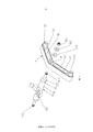
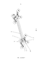
- Figure 1 is a schematic view showing the structure of a slide member of the present invention.
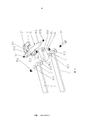
- FIG. 2 is a schematic structural view of a slide member of the present invention.
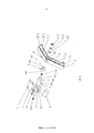
- FIG. 3 is a schematic structural view of a slide member according to the present invention.
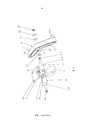
- Figure 4 is a schematic view showing the structure of the sliding member of the present invention.
- Figure 5 is a schematic view showing the structure of the sliding member of the present invention.
- Figure 6 is a schematic view showing the structure of the skateboard of the present invention.
- the skateboard member of the present invention includes a wheel axle frame 10 and a wheel carrier 11.
- the axle frame 10 includes a pivot shaft 101
- the pivot shaft 101 includes two first shaft segments 1011 and a second shaft segment 1012 extending in opposite directions.
- the first shaft segment 1011 and the second shaft segment 1012 respectively include a limiting member 103, the limiting member 103 is used to limit the range of motion when the wheel carrier 11 is pivotally connected to the axle frame 10.
- the wheel carrier 11 includes a pivot hole 111, and the pivot hole 111 is preferably disposed on the wheel frame 11 The middle position, but it can also be set at different positions of the wheel frame 11 according to actual needs.
- the wheel frame 11 has a first section 112 and a second section 113 extending from the pivot hole 111 toward opposite sides.
- First section 112 forms an angle with the second section 113.
- the wheel frame 11 forms an angle of less than 180 degrees toward the ground in contact with the wheel, such as 170 degrees or 160 degrees, and presents V. Type.
- the first section 112 and the second section 113 are respectively disposed at one end away from the pivot hole 111, and are respectively provided with a first axle 1121 and a second axle. 1131.
- the first axle 1121 and the second axle 1131 are respectively used to pivot the wheels.
- the first shaft segment 1011 and the second shaft segment 1012 are threaded near the outer side, and the wheel frame 11 passes through the pivot hole 111.
- the first shaft section 1011 and the second shaft section 1012 pivotally connected to the axle frame 10 are respectively transmitted through the elastic component 201, the washer 202 and the nut 203, such as rubber pads, to limit the wheel carrier. 11 Disengage the axle frame 10 .
- the axle frame 10 and the wheel carrier 11 can be made of metal materials such as aluminum or stainless steel, or it can be made of glass fiber or nylon.
- the first section 112 and/or the second section 113 of the wheel carrier 11 can optionally have a hollow portion 1122, 1132, by hollowing out the first section 112 and/or the second section 113 to reduce the weight of the wheel carrier 11, that is, the overall skateboard.
- the skateboard requires two front and rear axle frames 10, and the first axle segment 1011 and the second axle segment of each axle carrier 10 1012 is used for pivoting the two wheel frames 11 respectively.
- first axle segment 1011 and the second axle segment of each axle carrier 10 1012 is used for pivoting the two wheel frames 11 respectively.
- axle frame 10 and wheel carrier 11 Cooperating with the above-mentioned axle frame 10 and wheel carrier 11
- the structure of the wheel frame 11 provided on the front and rear sides of the skateboard can be adapted to the uneven road surface, the beating is reduced, and the smoothness of the sliding of the sliding plate is increased.
- the skateboard member of the present invention may further include a bottom plate 12, a lock bar 13, a fixing member 14 and a cushioning member 15
- the axle frame 10 can also include a through hole 102.
- the lock lever 13 is disposed in the through hole 102, and is fixed to the axle frame 10 and the bottom plate 12 through the fixing member 14.
- Base plate 12 A plurality of fixing holes 121 are defined, and the fixing holes 121 are used to lock the bottom plate 12, the axle frame 10 and the wheel frame 11 to the pedal of the sliding plate through a fastener such as a screw.
- Buffer member 15 The locking rod 13 is disposed in the through hole 102 and covers a portion thereof.
- the sectional area of the locking rod 13 is smaller than the diameter of the through hole 102, and the cushioning member 15 is at least partially disposed on the locking rod 13 and the through hole.
- the cushioning member 15 between the lock bar 13 and the through hole 102 may be made of rubber, for example, to provide a user with a large force applied to the left and right sides of the slide plate, and the slide plate together with the locked bottom plate. 12 and the lock lever 13 Tilt to the side where the force is applied to achieve the effect of turning the skateboard.
- the skateboard member of the present invention may further include an engaging member 16, a keel 17 and a fixing member 181, 182.
- the engaging member 16 includes a through hole 161 and a through hole 162 which is disposed in parallel with the through hole 102 of the wheel frame 10, and the through hole 162 is away from the through hole 161.
- the one end of the through hole 162 is perpendicular to the direction in which the through hole 161 is opened.
- the through hole 161 is perpendicular to the axial direction of the wheel frame 10, and the through hole 162 is compatible with the wheel frame 10.
- the axial relationship is horizontal.
- the keel 17 has a through hole 171 arranged in parallel with the through hole 162 .
- the through hole 162 In order to match the two axle frames 10 and the wheel frame 11 disposed in front and rear, there are two wheel axle frames 10 and two engaging members 16 and two keels 17, and two engaging members 16
- One end of the through hole 162 is oppositely disposed toward the inside of the slider.
- each of the skateboards uses two keels 17, and two keels 17 are provided on both sides of the engaging member 16, and each keel 17 A through hole 171 is defined at a position corresponding to the two through holes 162 at the front and the rear.
- the keel 171 is preferably an elongated sheet
- a fixing member such as a screw 181 and a nut 182 is used, that is, a screw 181
- the keel 17 and the joint member 16 are respectively inserted into the four through holes 171 of the two keels 17 and the eight washers 301 on the two sides of the four through holes 171, and then fixed to the nut 182. It is connected and connected to the axle frame 10 through the joint member 16.
- the aperture of the through hole 162 can be larger than the sectional area of the screw 181, that is, the through hole 162 provides the screw 181 in the through hole.
- the joint member 16 and the keel 17 may be made of a nylon material.
- the main purpose of setting the keel 17 is to use the keel when the user wants to step on the skateboard up and down stairs or other uneven road surface. It can directly contact the nosing of the stairs and use the keel 17 to support the skateboard so that the pedal portion of the skateboard is directly in contact with the lobes of the stairs, because the keel 17 The area in contact with the lobes of the stairs is much smaller than the contact area between the pedals and the lobes of the stairs, thus helping the skateboard to slide down smoothly from the stairs.
- the through hole 162 has a larger hole diameter than the screw 181
- the main purpose of the cross-sectional area of the fixing member is to provide a space in which the keel 17 is in contact with the lobes of the stairs and is subjected to an external force.
- the first shaft section 1011 and the second shaft section of the pivot shaft 101 of the axle frame 10 Each of the 1012 has two limiting members 103, and the two limiting members 103 are located between the middle portion and the opposite ends of the pivoting shaft 101.
- the wheel frame 11 faces the axle frame 10
- a side portion of the pivot hole 111 is further provided with a positioning portion 114.
- the sliding member of the present invention further includes two limiting members 19, and the limiting member 19 includes a positioning portion 191 and a through hole 192, and the positioning portion The 191 is engaged with the positioning portion 114.
- the limiting member 19 When the pivoting shaft 101 extends through the through hole 192 and the pivot hole 111, the limiting member 19 is interlocked with the wheel frame 11 and is supported by the limiting member 103 and the limiting member. The contact of 19 limits the range of actuation of the wheel carrier 11.
- the side of the limiting member 103 facing the wheel frame can form a slope 1031, and the limiting member 19 faces the limiting member 103.
- a slope 193 parallel to the slope 1031 of the stopper 103 can be formed.
- the stop member 19 can be made of nylon. If the above-mentioned limiting member 19 and the wheel carrier 11 are matched The interlocking member 103 and the limiting member 19 respectively have opposite parallel inclined faces 1031 and 193, and the nylon-shaped limiting member can be penetrated when the user slides on the uneven road surface or the stairs. 19 Limiting the amplitude of the interlocking wheel frame 11 to maintain the stability of the contact between the skateboard wheels and the ground or stairs.
- the limiting member 103 facing the wheel frame 10 directly facing the wheel frame 11 And a side of the pivot hole 111 is provided, for example, by an integral forming manner, and a slope 193 like the stopper 19 is provided.
- the difference from the foregoing embodiment lies in the stopper 103 and the slope 193.
- a cushioning member 40 which can be, for example, nylon or rubber.
- Figure 5 is a schematic structural view of the foregoing sliding plate member embodiments of the present invention, as shown in the figure, except that the sliding plate members are combined with each other, and two axle frames 10 are provided in front and rear.
- Two-sided wheel carrier 11 The first axle 1121 and the second axle 1131 are pivotally connected to the upper wheel 50, respectively.
- FIG. 6 is a structural schematic view of a sliding plate including the sliding member of the present invention.
- the pedal 60 includes a plurality of fixing holes 601.
- the plurality of fixing holes 601 at least partially correspond to the plurality of fixing holes 121.
- the plurality of fixing holes 121 on the bottom plate 12 and the corresponding plurality of fixing holes 601 are pierced by a fastener such as a screw. To lock the slider structure of the present invention shown in FIG. 5 to the pedal 60.
Landscapes
- Engineering & Computer Science (AREA)
- Chemical & Material Sciences (AREA)
- Combustion & Propulsion (AREA)
- Transportation (AREA)
- Mechanical Engineering (AREA)
- Motorcycle And Bicycle Frame (AREA)
Abstract
Priority Applications (5)
| Application Number | Priority Date | Filing Date | Title |
|---|---|---|---|
| JP2015551964A JP6095801B2 (ja) | 2013-01-14 | 2013-12-17 | スケートボード部材及び該スケートボード部材を有するスケートボード |
| EP13870536.3A EP2933176B1 (fr) | 2013-01-14 | 2013-12-17 | Élément de planche à roulettes et planche à roulettes comprenant celui-ci |
| AU2013372599A AU2013372599B2 (en) | 2013-01-14 | 2013-12-17 | Skateboard member and skateboard having same |
| CN201380064796.0A CN104936854B (zh) | 2013-01-14 | 2013-12-17 | 滑板构件及具有该滑板构件的滑板 |
| KR1020157019998A KR101675912B1 (ko) | 2013-01-14 | 2013-12-17 | 스케이트보드 부재 및 이를 포함하는 스케이트보드 |
Applications Claiming Priority (2)
| Application Number | Priority Date | Filing Date | Title |
|---|---|---|---|
| US13/740,528 US8807577B2 (en) | 2013-01-14 | 2013-01-14 | Skateboard assembly and skateboard having the same |
| US13/740,528 | 2013-01-14 |
Publications (1)
| Publication Number | Publication Date |
|---|---|
| WO2014108018A1 true WO2014108018A1 (fr) | 2014-07-17 |
Family
ID=51164583
Family Applications (1)
| Application Number | Title | Priority Date | Filing Date |
|---|---|---|---|
| PCT/CN2013/089634 Ceased WO2014108018A1 (fr) | 2013-01-14 | 2013-12-17 | Élément de planche à roulettes et planche à roulettes comprenant celui-ci |
Country Status (7)
| Country | Link |
|---|---|
| US (1) | US8807577B2 (fr) |
| EP (1) | EP2933176B1 (fr) |
| JP (1) | JP6095801B2 (fr) |
| KR (1) | KR101675912B1 (fr) |
| CN (1) | CN104936854B (fr) |
| AU (1) | AU2013372599B2 (fr) |
| WO (1) | WO2014108018A1 (fr) |
Families Citing this family (15)
| Publication number | Priority date | Publication date | Assignee | Title |
|---|---|---|---|---|
| US8801003B1 (en) * | 2010-09-08 | 2014-08-12 | Thomas Patrick Cassidy | Deck wheeled device |
| US9375632B1 (en) * | 2014-05-09 | 2016-06-28 | Michael Kish | Skateboard |
| US9492731B2 (en) * | 2014-09-16 | 2016-11-15 | Karsten Manufacturing Corporation | Dual axle skateboard and truck with outboard secondary wheels and method |
| USD738977S1 (en) * | 2014-10-09 | 2015-09-15 | Po-Chih Lai | Skateboard |
| CN105688401B (zh) * | 2014-11-28 | 2017-12-22 | 赖柏志 | 滑板构件 |
| US9573045B2 (en) * | 2014-11-28 | 2017-02-21 | Po-Chih Lai | Skateboard assembly |
| US10322332B2 (en) | 2016-12-30 | 2019-06-18 | Steen Strand | Laterally-sliding board with bifurcated trucks |
| CA3000376A1 (fr) * | 2017-05-23 | 2018-11-23 | Rolls-Royce Corporation | Assemblage de carenage de turbine comportant des segments de piste en composite a matrice ceramique dotes de fonctionnalites de fixation metallique |
| CN108905178B (zh) * | 2018-06-26 | 2019-09-24 | 陈永梅 | 一种多连杆排轮底座及其应用 |
| JP3223069U (ja) * | 2018-11-15 | 2019-09-12 | 久鼎金屬實業股▲分▼有限公司 | スケートボード |
| CN113874086B (zh) | 2019-03-22 | 2025-01-07 | 卡斯顿制造有限公司 | 带有多轮支架的滑板 |
| US12478857B2 (en) | 2020-06-29 | 2025-11-25 | Karsten Manufacturing Corporation | Multi-material skateboard deck |
| WO2022006171A1 (fr) | 2020-06-29 | 2022-01-06 | Karsten Manufacturing Corporation | Planches à roulettes pourvues d'un truck à roues multiples |
| KR20260003396A (ko) | 2020-08-21 | 2026-01-06 | 카스턴 매뉴팩츄어링 코오포레이숀 | 수하물용 멀티-휠 시스템 |
| WO2024211629A1 (fr) * | 2023-04-04 | 2024-10-10 | Karsten Manufacturing Corporation | Planches à roulettes pourvues d'un truck à roues multiples |
Citations (6)
| Publication number | Priority date | Publication date | Assignee | Title |
|---|---|---|---|---|
| US4062557A (en) * | 1976-08-19 | 1977-12-13 | Roden Harry F | Eight wheel skateboard |
| US6158753A (en) * | 1996-09-24 | 2000-12-12 | Sturbaum; Kurt H. | Skateboard having independent tandem wheels |
| CN2478643Y (zh) * | 2000-12-09 | 2002-02-27 | 光国股份有限公司 | 滑板支撑架 |
| CN2532893Y (zh) * | 2001-09-21 | 2003-01-29 | 吴煜池 | 运动滑板的滑轮结构 |
| US6536788B1 (en) * | 2000-10-30 | 2003-03-25 | Ferenc Kuncz | Skateboard integral interchangeable independent suspension truck-free with aerodynamic board design and rolling devices systems |
| US7484741B2 (en) * | 2005-12-05 | 2009-02-03 | Kay Iii John F | Axle assembly for skateboard |
Family Cites Families (12)
| Publication number | Priority date | Publication date | Assignee | Title |
|---|---|---|---|---|
| US4230330A (en) * | 1978-02-13 | 1980-10-28 | Carter Bros. Iron Works, Inc. | Skateboard |
| US4337961A (en) * | 1979-11-16 | 1982-07-06 | Covert William J | Skateboard |
| US4645223A (en) * | 1985-02-21 | 1987-02-24 | Grossman Richard D | Skateboard assembly |
| US5154436A (en) * | 1990-11-27 | 1992-10-13 | Jez Marek J | Wheeled riding apparatus |
| DE29509197U1 (de) * | 1995-06-02 | 1995-08-24 | Far Great Plastics Ind Co | Radhalterung für Rollbretter |
| FR2763002B1 (fr) * | 1997-05-06 | 1999-09-10 | Alain Lalondrelle | Train de roulement pour planches a roulettes et planche a roulettes equipee d'un tel train |
| US6182987B1 (en) * | 1999-09-08 | 2001-02-06 | Dwayne Lester Bryant | Truck assembly with replacable axles and ball joint pivots |
| FR2810894A1 (fr) * | 2000-07-03 | 2002-01-04 | Olivier Fremy | Dispositif pour planche a roulettes |
| AUPQ993700A0 (en) | 2000-09-06 | 2000-09-28 | Quinto Australia Pty Ltd | Improved truck for skateboard |
| US20030141688A1 (en) * | 2002-01-30 | 2003-07-31 | Lynn Ricky L. | Skateboard |
| US8186694B2 (en) * | 2009-06-24 | 2012-05-29 | Steven David Nelson | Steering assemblies, vehicles including a steering assemblies, and methods of steering a vehicle |
| WO2011008108A1 (fr) * | 2009-07-16 | 2011-01-20 | Instinct (2008) Limited | Planche à roulettes et bloc-essieu |
-
2013
- 2013-01-14 US US13/740,528 patent/US8807577B2/en active Active
- 2013-12-17 EP EP13870536.3A patent/EP2933176B1/fr not_active Not-in-force
- 2013-12-17 WO PCT/CN2013/089634 patent/WO2014108018A1/fr not_active Ceased
- 2013-12-17 CN CN201380064796.0A patent/CN104936854B/zh not_active Expired - Fee Related
- 2013-12-17 KR KR1020157019998A patent/KR101675912B1/ko not_active Expired - Fee Related
- 2013-12-17 AU AU2013372599A patent/AU2013372599B2/en not_active Ceased
- 2013-12-17 JP JP2015551964A patent/JP6095801B2/ja not_active Expired - Fee Related
Patent Citations (6)
| Publication number | Priority date | Publication date | Assignee | Title |
|---|---|---|---|---|
| US4062557A (en) * | 1976-08-19 | 1977-12-13 | Roden Harry F | Eight wheel skateboard |
| US6158753A (en) * | 1996-09-24 | 2000-12-12 | Sturbaum; Kurt H. | Skateboard having independent tandem wheels |
| US6536788B1 (en) * | 2000-10-30 | 2003-03-25 | Ferenc Kuncz | Skateboard integral interchangeable independent suspension truck-free with aerodynamic board design and rolling devices systems |
| CN2478643Y (zh) * | 2000-12-09 | 2002-02-27 | 光国股份有限公司 | 滑板支撑架 |
| CN2532893Y (zh) * | 2001-09-21 | 2003-01-29 | 吴煜池 | 运动滑板的滑轮结构 |
| US7484741B2 (en) * | 2005-12-05 | 2009-02-03 | Kay Iii John F | Axle assembly for skateboard |
Also Published As
| Publication number | Publication date |
|---|---|
| CN104936854A (zh) | 2015-09-23 |
| AU2013372599B2 (en) | 2016-02-11 |
| EP2933176A1 (fr) | 2015-10-21 |
| EP2933176A4 (fr) | 2016-08-24 |
| CN104936854B (zh) | 2017-06-23 |
| AU2013372599A1 (en) | 2015-07-30 |
| JP2016502894A (ja) | 2016-02-01 |
| JP6095801B2 (ja) | 2017-03-15 |
| KR101675912B1 (ko) | 2016-11-14 |
| EP2933176B1 (fr) | 2019-10-30 |
| US8807577B2 (en) | 2014-08-19 |
| KR20150098674A (ko) | 2015-08-28 |
| US20140197611A1 (en) | 2014-07-17 |
Similar Documents
| Publication | Publication Date | Title |
|---|---|---|
| WO2014108018A1 (fr) | Élément de planche à roulettes et planche à roulettes comprenant celui-ci | |
| US3706437A (en) | Clamp for optical instruments and the like | |
| US9776069B2 (en) | Stroller-attachable skateboard apparatus | |
| JPH052955Y2 (fr) | ||
| WO2014183441A1 (fr) | Ensemble avant de vélo et vélo | |
| WO2017115880A1 (fr) | Balai d'essuie-glace de type ensemble coulissant à simple appui | |
| WO2016082688A1 (fr) | Planche à roulettes et élément constitutif de planches à roulettes | |
| TWI775511B (zh) | 用於高架地板之支撐裝置 | |
| CN114294539B (zh) | 一种通用航空飞机座舱内监控支架结构 | |
| TWM459170U (zh) | 自行車握把之快拆結構 | |
| JP2565715Y2 (ja) | 引出しパネルの調節自在な支持装置 | |
| CN110158827B (zh) | 一种角度可调式副框系统 | |
| CN203344849U (zh) | 车用数码产品固定装置 | |
| TWI583855B (zh) | 外牆結構 | |
| CN223791652U (zh) | 一种折叠器及折叠车架 | |
| CN111396712A (zh) | 一种监控视频活动安装架及其安装方法 | |
| CN222909357U (zh) | 一种用于地砖铺贴的找平装置 | |
| CN216343324U (zh) | 一种自锁式螺丝紧固件 | |
| JP2000272880A (ja) | 伸縮ブームのスライドプレート支持構造 | |
| JP2004109757A (ja) | のぼり籏竿の支持具 | |
| JP2627855B2 (ja) | カメラにおけるレンズの固定装置 | |
| CN108612994B (zh) | 一种信息显示字母板及其安装固定结构 | |
| CN206856890U (zh) | 自行车架的折叠结构 | |
| JP3830763B2 (ja) | 離間した部材への装着装置 | |
| TW202426275A (zh) | 腳輪防鬆脫結構 |
Legal Events
| Date | Code | Title | Description |
|---|---|---|---|
| 121 | Ep: the epo has been informed by wipo that ep was designated in this application |
Ref document number: 13870536 Country of ref document: EP Kind code of ref document: A1 |
|
| ENP | Entry into the national phase |
Ref document number: 2015551964 Country of ref document: JP Kind code of ref document: A |
|
| NENP | Non-entry into the national phase |
Ref country code: DE |
|
| WWE | Wipo information: entry into national phase |
Ref document number: 2013870536 Country of ref document: EP |
|
| ENP | Entry into the national phase |
Ref document number: 20157019998 Country of ref document: KR Kind code of ref document: A |
|
| ENP | Entry into the national phase |
Ref document number: 2013372599 Country of ref document: AU Date of ref document: 20131217 Kind code of ref document: A |