EP2933211B1 - Verfahren und systeme zum bearbeiten von filmen in verpackungsmaschinen - Google Patents
Verfahren und systeme zum bearbeiten von filmen in verpackungsmaschinen Download PDFInfo
- Publication number
- EP2933211B1 EP2933211B1 EP15157842.4A EP15157842A EP2933211B1 EP 2933211 B1 EP2933211 B1 EP 2933211B1 EP 15157842 A EP15157842 A EP 15157842A EP 2933211 B1 EP2933211 B1 EP 2933211B1
- Authority
- EP
- European Patent Office
- Prior art keywords
- film
- roll
- film roll
- robot
- leading end
- Prior art date
- Legal status (The legal status is an assumption and is not a legal conclusion. Google has not performed a legal analysis and makes no representation as to the accuracy of the status listed.)
- Not-in-force
Links
Images


Classifications
-
- B—PERFORMING OPERATIONS; TRANSPORTING
- B65—CONVEYING; PACKING; STORING; HANDLING THIN OR FILAMENTARY MATERIAL
- B65H—HANDLING THIN OR FILAMENTARY MATERIAL, e.g. SHEETS, WEBS, CABLES
- B65H19/00—Changing the web roll
- B65H19/10—Changing the web roll in unwinding mechanisms or in connection with unwinding operations
- B65H19/12—Lifting, transporting, or inserting the web roll; Removing empty core
-
- B—PERFORMING OPERATIONS; TRANSPORTING
- B65—CONVEYING; PACKING; STORING; HANDLING THIN OR FILAMENTARY MATERIAL
- B65H—HANDLING THIN OR FILAMENTARY MATERIAL, e.g. SHEETS, WEBS, CABLES
- B65H19/00—Changing the web roll
- B65H19/10—Changing the web roll in unwinding mechanisms or in connection with unwinding operations
- B65H19/18—Attaching, e.g. pasting, the replacement web to the expiring web
- B65H19/1842—Attaching, e.g. pasting, the replacement web to the expiring web standing splicing, i.e. the expiring web being stationary during splicing contact
- B65H19/1847—Attaching, e.g. pasting, the replacement web to the expiring web standing splicing, i.e. the expiring web being stationary during splicing contact taking place on the replacement roll
-
- B—PERFORMING OPERATIONS; TRANSPORTING
- B65—CONVEYING; PACKING; STORING; HANDLING THIN OR FILAMENTARY MATERIAL
- B65H—HANDLING THIN OR FILAMENTARY MATERIAL, e.g. SHEETS, WEBS, CABLES
- B65H19/00—Changing the web roll
- B65H19/10—Changing the web roll in unwinding mechanisms or in connection with unwinding operations
- B65H19/18—Attaching, e.g. pasting, the replacement web to the expiring web
- B65H19/1857—Support arrangement of web rolls
- B65H19/1878—Support arrangement of web rolls with one stationary support for the rolls
-
- B—PERFORMING OPERATIONS; TRANSPORTING
- B65—CONVEYING; PACKING; STORING; HANDLING THIN OR FILAMENTARY MATERIAL
- B65H—HANDLING THIN OR FILAMENTARY MATERIAL, e.g. SHEETS, WEBS, CABLES
- B65H2301/00—Handling processes for sheets or webs
- B65H2301/40—Type of handling process
- B65H2301/41—Winding, unwinding
- B65H2301/417—Handling or changing web rolls
- B65H2301/4171—Handling web roll
- B65H2301/4173—Handling web roll by central portion, e.g. gripping central portion
-
- B—PERFORMING OPERATIONS; TRANSPORTING
- B65—CONVEYING; PACKING; STORING; HANDLING THIN OR FILAMENTARY MATERIAL
- B65H—HANDLING THIN OR FILAMENTARY MATERIAL, e.g. SHEETS, WEBS, CABLES
- B65H2301/00—Handling processes for sheets or webs
- B65H2301/40—Type of handling process
- B65H2301/41—Winding, unwinding
- B65H2301/417—Handling or changing web rolls
- B65H2301/418—Changing web roll
- B65H2301/4185—Core or mandrel discharge or removal, also organisation of core removal
- B65H2301/4186—Core or mandrel discharge or removal, also organisation of core removal by lifting or lowering device, e.g. crane
-
- B—PERFORMING OPERATIONS; TRANSPORTING
- B65—CONVEYING; PACKING; STORING; HANDLING THIN OR FILAMENTARY MATERIAL
- B65H—HANDLING THIN OR FILAMENTARY MATERIAL, e.g. SHEETS, WEBS, CABLES
- B65H2301/00—Handling processes for sheets or webs
- B65H2301/40—Type of handling process
- B65H2301/46—Splicing
- B65H2301/4606—Preparing leading edge for splicing
-
- B—PERFORMING OPERATIONS; TRANSPORTING
- B65—CONVEYING; PACKING; STORING; HANDLING THIN OR FILAMENTARY MATERIAL
- B65H—HANDLING THIN OR FILAMENTARY MATERIAL, e.g. SHEETS, WEBS, CABLES
- B65H2511/00—Dimensions; Position; Numbers; Identification; Occurrences
- B65H2511/20—Location in space
-
- B—PERFORMING OPERATIONS; TRANSPORTING
- B65—CONVEYING; PACKING; STORING; HANDLING THIN OR FILAMENTARY MATERIAL
- B65H—HANDLING THIN OR FILAMENTARY MATERIAL, e.g. SHEETS, WEBS, CABLES
- B65H2555/00—Actuating means
- B65H2555/30—Multi-axis
-
- B—PERFORMING OPERATIONS; TRANSPORTING
- B65—CONVEYING; PACKING; STORING; HANDLING THIN OR FILAMENTARY MATERIAL
- B65H—HANDLING THIN OR FILAMENTARY MATERIAL, e.g. SHEETS, WEBS, CABLES
- B65H2701/00—Handled material; Storage means
- B65H2701/10—Handled articles or webs
- B65H2701/19—Specific article or web
- B65H2701/1944—Wrapping or packing material
Definitions
- Embodiments of the present disclosure relate to methods and systems for processing films in packaging machines.
- a packaging machine has been known that may used for forming packages from a film continuously unwound from a film roll.
- the film of the film roll being used (hereinafter called "old film roll") has been used up
- the film of the old film roll may be connected to a film of a new film roll by way of a film connecting device, so that the old film roll can be exchange with the new film roll.
- a film connecting device In order to minimize troublesome operations by the operator, it has been desired to automate the operation for exchanging the old film roll with the new film roll.
- Japanese Laid-Open Patent Publication No. 2000-264509 has proposed a connecting device that utilizes a robot.
- Document JP 2005 231789 discloses a robot system for automatically connecting a new film and changing a roll of film.
- This system comprises a storage section, cutting device, film holding device and a connecting device.
- the robot operates only for transferring a film roll between a pallet and the connecting device.
- the robot is not fully used for the connecting operation.
- a film processing method may be provided for automatically connecting a film of a first film roll and a film of a second film roll to be exchanged with the first film roll in a packaging machine.
- a film of the first film roll may be held at a holding position by a holding device, while the first film roll is supported by a robot, and the film is unwound from the first film roll and extends to a former in a tensioned state.
- a cutting device may be operated for automatically cutting the film of the first film roll at a cutting position on an upstream side of the holding position with respect to a feeding direction toward the former while the film is held by the holding device.
- the robot may be operated for moving the first film roll having the film automatically cut to a storage section, so that the first film roll is stored at a storage section.
- the storage section may be located within a movable range of the robot and may store the second film roll.
- the robot may be operated for taking out the second film roll from the storage section, rotatably supporting the second film roll, and moving the second film roll to a connecting position where a film leading end of a film of the second film roll overlaps with a film terminal end of the film of the first film roll remained on a downstream side of the cut position and held by the holding device.
- the film terminal end of the first film roll and the film leading end of the second film roll may be connected by a connecting device at the same time the film leading end overlaps with the film terminal end or after the film leading end has overlapped with the film terminal end. Thereafter, the robot may be operated for moving the second film roll from the connecting position to a set position spaced from the connecting position after connecting the films by the connecting device, so that the film of the second film roll is tensioned for feeding to the former.
- the second film roll taken out from the storage section may be positioned at a connection preparation section by the operation of the robot.
- the connecting preparation section may be located within the movable range of the robot.
- An adhesive may be used as the connecting device and may be applied to the film leading end of the film of the second film roll positioned at the connection preparation section, so that the film leading end of the film of the second film roll and the film terminal end of the film of the first film roll are connected to each other by the adhesive at the same time the film leading end overlaps with the film terminal end as a result of movement of the second film roll to the connecting position from the connection preparation section.
- the robot can adjust the position of the film roll so as to be suitable for applying the adhesive according to the rolled diameter or the width of the film roll to be used. Therefore, it may be possible to further increase a possibility in design.
- the film leading end of the second film roll may be attached to a circumferential surface of the second film roll by an adhesive before the second film roll is stored in the storage section.
- the film leading end of the second film roll may be separated from the circumferential surface of the second film roll against an adhesive force of the adhesive.
- the adhesive force of the adhesive may be smaller than a connecting force between the film leading end of the second film roll and the film terminal end of the first second film roll connected by the connecting device.
- the film leading end attached to the circumferential surface of the second film roll by the adhesive may be separated from the circumferential surface. Therefore, it may be possible to achieve simplification, for example, by omitting a dedicated device for separating the film leading end from the circumferential surface of the second film roll.
- a first adhesive may be applied to one of side edges with respect to a widthwise direction of a part of the film of the first film roll held by the holding device before the film of the first film roll is cut at the cutting position by the cutting device. After the film of the first film roll has been cut, the part of the film may form the film terminal end of the first film roll and may be held by the holding device.
- a second adhesive may be used as the connecting device and may be applied to the film leading end of the film of the second film roll before the movement of the second film roll to the connecting position, so that the film leading end of the film of the second film roll and the film terminal end of the film of the first film roll are connected to each other by the first adhesive and the second adhesive at the same time the film leading end overlaps with the film terminal end as a result of movement of the second film roll to the connecting position after the second adhesive has been applied to the second film roll.
- the second adhesive may extend from a position proximal to a film attaching position in the widthwise direction away from the film attaching position.
- the film attaching position may be set to correspond to a position of the first adhesive applied to the film of the first film roll.
- the second adhesive may be applied to the film leading end of the film of the second film roll such that the second adhesive extends from a position proximal to the film attaching position in the widthwise direction away from the film attaching position.
- the film attaching position may be set to correspond to a position of the first adhesive applied to the film of the first film roll. Therefore, it may be possible to apply the second adhesive at a desired position without causing the film leading end of the film to be tuned upward or downward.
- the film attaching position, where no second adhesive is applied may be adhered to one of side edges of the part of the film forming the film terminal end by the first adhesive. Therefore, it may be possible to prevent the film leading end and the film terminal end from being tuned up or down during the passage of the film along rollers or through the former of the packaging machine.
- the robot may include a first arm and a second arm each having a support portion.
- the first arm may rotatably support the second film roll.
- the second arm may support the cutting device.
- a film processing system may be provided for automatically connecting a film of a first film roll and a film of a second film roll to be exchanged with the first film roll in a packaging machine.
- the film processing system may include a robot configured to operate according to a film roll exchange command; a cutting device configured to automatically cut the film of the first film roll at a cut position when the film of the first film roll is unwound from the first film roll so as to extend to a former in a tensioned state while the first film roll is supported by the robot; a film holding device configured to hold a film terminal end of the film of the first film roll at a holding position on a downstream side of the cut position with respect to a feeding direction toward the former when the films is cut by the cutting device; and a storage section located within a movable range of the robot and configured to store the first film roll and the second film roll.
- the robot may be configured to move the first film roll to the storage section after the film has been cut, so that the first film roll is stored at the storage section.
- the robot may be further configured to take out the second film roll from the storage section, transfer the second film roll to a connecting position, rotatably support the second film roll at the connecting position, and moving a film leading end of the second film roll such that the film leading end overlaps with the film terminal end of the film of the first film roll remained after being cut and held by the film holding device.
- the film processing system may further include a connecting device configured to connect the film leading end of the second film roll to the film terminal end of the film of the first film roll at the same time the film leading end overlaps with the film terminal end or after that film leading end has overlapped with the film terminal end.
- the robot may be further configured to transfer the second film roll from the connecting position to a set position after the films have been connected by the connecting device, so that the film of the second film roll is tensioned for feeding to the former.
- the film processing system may further include a film receiving device disposed at a position on an upstream side with respect to the feeding direction of the film holding device and configured to support the film of the first film roll in a tensioned state.
- a space may be defined between the film receiving device and the film holding device to allow a cutting tool of the cutting device to move into the space.
- the cutting tool in order to cut the film in the tensioned state, the cutting tool may move into the space defined between the film receiving device and the film holding device. Therefore, it is possible to reduce the risk of damage to the cutting tool. In addition, it is possible to neatly cut the film.
- the film holding device may be a film suction device. By holding the film by using the film suction device, it may be possible to hold the film without damaging the film.
- the film processing system may further include a film incident angle adjusting device disposed along a film feeding path between the former and the first film roll or the second film roll and configured to adjust an incident angle of the film with respect to the former.
- the film incident angle adjusting device may include a single guide roller configured to engage the film.
- the incident angle of the film with respect to the former can be adjusted by the film incident angle adjusting device.
- the film incident angle adjustment device may include a single guide roller, it may be possible to simplify the construction of the packaging machine along the feeding path between the film roll and the former.
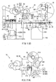
- FIG. 1 there is shown a horizontal form-fill packaging machine 10.
- a web-like film 30F unwound from a film roll 30 may be processed by a former 20 that may fold the film 30F such that opposite side edges in the widthwise direction of the film 30F are lapped with each other.
- the lapped side edges may be sealed in the lengthwise direction by a lengthwise sealing device 24, so that the film 30F is formed into a tubular film 30F.
- a conveyer 22 may transfer the tubular film 30.
- articles may be filled into the tubular film 30F at predetermined intervals while an end sealer 26 may seal the tubular film 30F in a direction transverse to the transferring direction at positions on a front side and a rear side with respect to the transferring direction of each of the articles.
- the tubular film 30F may be cut at the transverse seal portions, so that a plurality of packages each containing the article can be manufactured.
- the horizontal form-fill packaging machine 10 may further include a robot 50.
- the robot 50 may operate upon receipt of an exchange command for exchanging the film roll 30 with a film roll 40.
- the film roll 30 to be exchanged with the film roll 40 will be hereinafter also called “an old film roll 30", and the film roll 40 will be hereinafter also called “a new film roll 40").
- the exchange command may be generated based on information from a detecting device that may detect the residual amount of the film 30F of the film roll 30 that is being used, or based on information regarding change of articles to be filled.
- the robot 50 may operate to transfer the film 30F of the film roll 30 that is being used, transfer a film 40F of a film roll 40 (hereinafter also called “new film roll 40) to be exchanged with the film roll 30, and connect the film 30F of the film roll 30 and the film 40F of the film roll 40F to each other as will be explained later.
- new film roll 40 a film roll 40
- the robot 50 may be a dual-armed 15-axis multijoint robot and may have a first arm 51 and a second arm 52 that respectively have a first support portion 51H and a second support portion 52H connected to their leading ends.
- Each of the first arm 51 and the second arm 52 may have a plurality of arm portions joined in series with each other by a plurality of joints that may be similar to a human shoulder joint or a human elbow joint, so that each of the arms is allowed for a rotational movement and a bending and stretching movement.
- the first support portion 51H may be designed for exchangeably supporting the film roll 30 and the film roll 40, while the second support portion 52H may be designed for exchangeably supporting various working tools used for the connecting operation.
- the film roll 30 or 40 supported by the first support portion 51H and the working tool(s) supported by the second support portion 52H may be moved along suitable linear paths within a three-dimensional space defined by an upward and downward axis, a frontward and rearward axis and a leftward and rightward axis.
- the first arm 51 may include a motor or any other drive device that can rotate the first support portion 51H together with the supported film roll 30 or 40 relative to the arm 51 and can stop the rotation at a desired rotational position.
- the second arm 52 may include a motor or any other drive device that can rotate the second support portion 52H together with the working tool(s) relative to the arm 52 and can stop the rotation at a desired rotational position.
- the robot 50 may be arranged at a position spaced laterally from the conveyer 22.
- the robot 50 may include a controller coupled to a control device that may control the packaging operation of the packaging machine 10.
- the controller of the robot 50 may receive various operation commands including the roller exchange command from the control device of the packaging machine 10. Therefore, according to the operation commands, the robot 50. may operate for cutting the film, transferring the film roll 30 or 40, and supporting the film roll 30 or 40 and the working tool(s).
- the first arm 51 may be located on an article discharge side (front side), while the second arm 52 may be located on an article supply side (rear side).
- Each of the first support portion 51H and the second support portion 52H respectively connected to the first arm 51H and the second arm 52H may include a plurality of engaging members 55 that can move into and out of the outer peripheral surface of the first support portion 51H or the second support portion 52H.
- a first setting section 100 may serve as a storage section capable of supporting and storing the film roll 30 and the film roll 40 (or a plurality of film rolls 40).
- a second setting section 200 and a connection preparation section 90 may be arranged within the movable range of the second arm 52.
- the second setting section 200 may support and store a plurality of connection working tools 210 and 220 that may be detachably mounted to the second support portion 52H and may be used for the film connecting operation that will be described later.
- the engaging members 55 of the first support portion 51H can be engaged with and disengaged from attachment holes 32 formed in the inner circumferential surfaces of the film roll 30, so that the film roll 30 can be prevented from rotating relative to the first support portion 51H and can be permitted to rotate relative to the first support portion 51H.
- the engaging members 55 of the first support portion 51H can be engaged with and disengaged from attachment holes 42 formed in the inner circumferential surface of the film roll 40, so that the film roll 40 can be prevented from rotating relative to the first support portion 51H and can be permitted to rotate relative to the first support portion 51H.
- each of the connection working tools 210 and 220 may have attachment holes 24 formed in the inner circumferential surface thereof.
- the engaging members 55 of the second support portion 52H can be engaged with and disengaged from the attachment holes 24 of the connection working tool 210 or 220, so that the connection working tool 210 or 220 can be prevented from rotating relative to the second support portion 52H and can be permitted to rotate relative to the second support portion 52H.
- the robot 50 may operate to move the first support portion 51H such that the film roll 40 moves from a film connecting position above the conveyor 22 to a set position spaced obliquely rearward and upward of the film connection position and is thereafter held at the set position.
- the robot 50 may serve as a positioning device for positioning the film roll 40 at the set position.
- the first support portion 51H may serve as a film roll support device for rotatably supporting the film roll 40 about an axis extending in a horizontal direction.
- the film roll support device may be a part of a film supply section 80 for supplying the film 40F in a form of a web to the former 20.
- the robot 50 may operate to move the first arm 51 such that (i) the first arm 51 having the film roll 30 supported thereon transfers the film roll 30 to an old film roll storing position of the first setting section 100; (ii) the first arm 51 takes a new film roll 40 from a new film roll storing position of the first setting section 100 and transfers the new film roll 40 to the set position; and (iii) the first arm 51 transfers the film 40F of the new film roll 40 to the film connecting position for connection with the film 30F of the old film roll 30.
- the robot 50 may operate to move the second arm 52 such that (a) at the second set section 200, the second support portion 52H engages and holds each of the connection working tool 210 and 220 used for automatically exchanging the film roll 30 with the film roll 40 and for automatically connecting the film 30F and the film 40F; and (b) the second arm 52 moves to return each of the connection working tools 210 and 220 to its original storing position of the second set section 200 after the operation of each of the connection working tools 210 and 220 has been finished.
- the film supply section 80 may be arranged between the former 20 and the first support portion 51H serving as the film roll support device for supporting the film roll at the set position.
- the film supply section 80 may include a feeding device 81 that may include a drive roller 82 and a driven roller 83.
- the drive roller 82 may be rotatably driven by a servo motor M or any other suitable drive device.
- the film 30F (or 40F) drawn from the film roll 30 (or 40) positioned at the set position may extend along the circumferential surface of the drive roller 82, thereafter extend along the circumferential surface of the driven roller 83 disposed to be opposed to the drive roller 82 at a position obliquely forward and upward thereof, and subsequently extend toward the former 20 that is located on the lower side of the driven roller 83.
- the drive roller 82, the driven roller 83 and the servo motor M constituting the feeding device 80 may be supported as a unit by a body frame W via a slide support mechanism (not shown) that may support the unit such that the unit can slidably move relative to the body frame W both in frontward and rearward directions and in upward and downward directions in order to allow adjustment of the position of the unit.
- a slide support mechanism (not shown) that may support the unit such that the unit can slidably move relative to the body frame W both in frontward and rearward directions and in upward and downward directions in order to allow adjustment of the position of the unit.
- By adjusting the position of the unit it may be possible to adjust an incident angle of the film 30F (or 40F) extending from the driven roller 83 toward the former 20.
- the unit in association with the slide support mechanism may serve as a film incident angle adjusting device.
- the driven roller 83 may serve as a film incident angle adjusting roller.
- the film supply section 80 provided between the first support portion 51H and the former 20 may include the film incident angle adjusting roller that may also serve as a guide roller for the film 30F (or 40F). Therefore, the construction of the film supply section 80 can be simplified.
- connection operation section 70 may act on a part of the film 30F extending from the film roll 30 to the drive roller 82, so that the film 30F is tensioned to extend in a film feeding direction while the film 30F maintaining a web form. Even after the film roll 30 has moved from the set position to the tensioning position, a relatively weak braking force may be applied to the first support portion 51H against its rotation, so that the film 30F can be kept in the tensioned state.
- connection operation section 70 may serve as a film tensioning device for tensioning the film 30F, for example, during a cutting operation of the film 30F as will be explained later.
- the connection operation section 70 may include a film support portion 72, a film suction portion 74 (film holding device) and a film receiving portion 78.
- the film support portion 72 may include a flat surface portion 72A that may be made of elastically deformable member, so that the flat surface portion 72A can elastically support the films 30F and 40F when the robot 50 has operated to press a front surface of a leading end 40FA of the film 40F, to which a double-sided adhesive tape 96 with adhesive serving as a connecting device is attached, against a back surface of a terminal end 30FZ of the film 30F (see FIGS. 6(A) and 6(B) ).
- the film suction portion 74 may be spaced upward from the film support portion 72 and may include a suction surface 74A for sectioning the film 30F.
- the suction surface 74A may extend substantially within the same plane as the flat surface portion 72A or may be positioned to extend rearward therefrom.
- the film receiving portion 78 may be spaced upward from the film suction portion 74 and may include a flat surface portion 78A that can support the film 30F at a position frontward of the film suction portion 74.
- a slot or a space 76 may be defined between the film suction portion 74 and the film receiving portion 78, so that cutting edges of cutters 222A and 222B serving as a part of a cutting device can move into and out of the space 76 for cutting the tensioned film 30F according to command signals regarding the film cutting operation, which may be outputted from the controller.
- the flat portions 72A and 78A and the suction surface 74A may have widths each greater than the width of the film 30F and the film 40F and may extend parallel to each other.
- the positions of the film support portion 72, the film suction portion 74, the film receiving portion 78 and the film feeding section 80 along the feeding direction may be determined such that when the film roll 30 is positioned at the tensioning position, irrespective of possible change of the diameter of the film roll 30, (1) the film 30F may extend toward the flat surface portion 78A from the front side thereof so as to always contact with the flat surface portion 78A so as to ensure that the suction surface 74A contacts the tensioned film 30F; and (2) the outer circumferential surfaces of the film roll 30 and 40 do not contact or interfere with the suction surface 74A of the suction portion 74 when the film 30F is pressed against the flat surface portion 72A of the film support portion 72..
- the connection preparation section 90 may include a mark detection device 92 and a tape attaching device 94.
- the mark detection device 92 may detect a mark MK marked on at least a part of the circumferential surface of the new film roll 40 and indicative of the film leading end 40FA.
- the tape attaching device 94 may attach the double-sided adhesive tape 96 (with the adhesive serving as the connecting device) to the front surface of the film leading end 40FA.
- the tape attaching device 94 may include a block 97 and a claw 97a extending from the block 97.
- the block 97 is biased by a spring and movable along a rod 98 in a horizontal direction.
- the film roll 40 may be moved according to the movement of the first, arm 51 such that (a) the film roll 40 engages the claw 97a positioned to be spaced from an upper end of a carrier of the double-sided adhesive tape 96 by a distance L, and (b) the film roll 40 moves the block 97 via the claw 97a in a horizontal direction along the rod 98 be compressing the spring as shown in FIG. 5(B) .
- the double-sided adhesive tape 96 may contact with the film leading end 40FA of the film roll 40 so as to be attached to extend in a widthwise direction of the film start end 40FA.
- the first set section 100 may include a loading surface 102, where the film rolls 30 and 40 can be set.
- the loading surface 102 may include a plurality of upwardly oriented projections 104 at positions corresponding to the storing positions of the film rolls 30 and 40.
- the projections 104 may have an outer diameter sized for fitting into the attachment hole 32 formed in the film roll 30 to extend along the central axis thereof and for fitting into the attachment hole 42 formed in the film roll 40 to extend along the central axis thereof.
- An upper end portion 104A (see FIG.
- each projection 104 is shaped such that each projection 104 can support the film roll 30 (or 40) in such a manner that the axis of the attachment hole 32 (or 42) of the film roll 30 (or 40) is oriented vertically even in the case that the film 30F (or 40F) of the film roll 30 (or 40) is wound eccentrically relative to the axis of the attachment hole 32 (or 42). Therefore, the first support portion 51H can reliably engage the attachment hole 32 (or 42) by the engaging members 55.
- the first set section 100 may further include a plurality of film roll detection devices 106 that can detect whether or not each of the film rolls 30 and 40 is set at the first set section 100.
- the robot 50 can set the film roll 30 at any of the storing positions where no film roll is stored, and the robot 50 may take out the film roll 40 to be exchanged with the film roll 30, from its storing position according to the exchange command.
- connection operation tools 210 and 220 for attachment to the second support portion 52H may be loaded on the second set section 200.
- the connection operation tool 210 and the connection operation tool 220 will be hereinafter also called a first tool 210 and a second tool 220, respectively.
- the first tool 210 may include a marking device 212 and a container 214 attached to a hollow cylindrical body at positions spaced from each other by a given distance.
- the marking device 212 may be a permanent marker.
- the container 214 may contain glue or any other suitable adhesive.
- An applicator 214a may be attached to a tip end of a container body of the container 214 for applying the glue to the film 30F as will be explained later.
- Covers may be disposed at the second set section 200 and can be fitted with the applicator 214a and a marker tip 212a of the marking device 212, which may be a pen tip of a permanent marker, so that the applicator 214a and the marker tip 212a may be prevented from drying out.
- the second tool 220 may include two different kinds of cutters 222A and 222B and an elastically deformable film holder 224 that are attached to a hollow cylindrical body at positions spaced from each other by given distances.
- the second set section 200 may be provided with positioning guides 230 that can support the first and second tools 210 and 220 in such a manner that the first and second tools 210 and 220 are oriented vertically in an upright manner and are positioned with respect to the circumferential direction about their respective hollow cylindrical bodies for alignment with the second support portion 52H with respect to the rotational direction thereof.
- the film roll 30 may be automatically exchanged with the film roll 40, and the film 30F of the film roll 30 may be automatically connected to the film 40F of the film roll 40 as will be hereinafter described.
- the film roll 30 may be supported by the first support portion 51H and may be positioned to be fixed at the set position by the first arm 51, while the film 30F is guided by the feeding device 81 so as to be fed to the former 20.
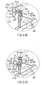
- the robot 50 may automatically perform the connecting operation of the film 30F of the film roll 30 and the film 40F of the film roll 40. To this end, as shown in FIGS. 1(A) and 1(B) and FIG.
- the first arm 51 may move the film roll 30 from the set position to the tensioning position obliquely forward and upward of the set position in a parallel translation manner, while the first support portion 51H may apply a weak braking force to the film roll 30 against its rotation.
- the braking force may be small enough to allow rotation of the film roll 30. Therefore, the film 30 may be drawn or unwound from the film roll 30, while the flat surface portion 78A and the suction surface 74A and the flat surface portion 72A are in contact with the film 30F to keep a part of the film 30F on an upstream side of the drive roller 82 in a tensioned state.
- the film 30F may be suctioned by the suction portion 74 (film holding device) and may be held in position.
- the suctioned state of the film 30F may be maintained until the connecting operation of the films 30F and the film 40F is completed.
- the second arm 52 may be moved for taking out the first tool 210 (including the marking device 212 and the glue container 214) from the second set section 200 and for holding the first tool 210.
- the second arm 52 moves the first tool 210 to a position on the rear side of the connecting operation section 70, where the applicator 214a may apply the glue to the back surface of the film 30F at two positions as shown in FIGS. 2(B) and 2(C) .
- One of the two positions where the glue is applied may be determined at a central portion 30FC with respect to the widthwise direction of a part the film 30F, which forms a film leading end 30FA of the film 30F when the film 30F is cut after being drawn from the film roll 30, and which is supported by the flat surface portion 78A (see FIG. 2(B) ).
- the other of the two positions may be determined at a side edge 30FS on one side with respect to the widthwise direction of a part of the film 30F, which forms a film terminal end 30FZ of the film 30F on the downstream side of the cut position of the film 30F with respect to the feeding direction, and which is supported by the flat surface portion 72A (see FIG 2(C) and FIG. 3(B) ).
- the second support portion 52H may rotate to position the marking device 212 of the first tool 10 so as to face the film 30F as shown in FIG. 2(D) , and after that, the marking device 212 may be operated to put a mark MK on the back surface of a part of the film 30F, which is supported by the flat surface portion 78A.
- the position of the mark MK may be determined at one of the side edges with respect to the widthwise direction of the film 30F and nearer to the film roll 30 than the applying position of the glue to the central portion 30FC.
- the robot 50 may operate the second arm 52 to return the first tool 210 to the original storage position of the second set section 200. Thereafter, the second arm 52 may take out the second tool 220 (including the cutters 222A and 222B and the film holder 224) from the second set section 200 and holds the second tool 220. After that, the second arm 52 may move the second tool 220 to a position on the rear side of the connecting operation section 70 as shown in FIG 3(A) . At this position, the second tool 220 may automatically cut a part of the tensioned film 30F, which is opposed to the space 76 defined between the suction portion 74 and the film receiving portion 78.
- the cutting edge of cutter 222A may move into the space 76 such that (a) the cutting edge first cuts through a substantially central portion with respect to the widthwise direction of the part of the film 30F facing the space 76 and (b) the cutting edge thereafter moves along the length of the space 76 extending in the widthwise direction of the film 30F to cut the film 30F by a length corresponding to a substantially half the width of the film 30F
- the second support portion 52H may rotate to move the cutting edge of the cutter 222B into the space 76.
- the cutting edge of the cutter 222B may be oriented in a different direction from that of the cutter 222A.
- the cutting edge of the second cutter 222B may first move into the substantially central portion of the film 30F and may thereafter move along the length of the space 76 to cut the film 30F by a length corresponding to the remaining half of the width of the film 30F.
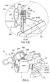
- the first arm 51 may move the film roll 30 rearward from the tensioning position to a position shown in FIG 4 , where the film holder 224 of the second support portion 52H may hold the central portion with respect to the widthwise direction of the outer circumferential surface of the film roll 30.
- the first support portion 51H may be driven to rotate the film roll 30, so that the unwound part of the film 30F can be rewound by the film roll 30.
- the film holder 224 may press the film leading end 30FA, which has the glue applied to the back surface, against the circumferential surface of the film roll 30 from the side of the front surface of the film leading end 30FA, so that the film leading end 30FA can be adhered to the circumferential surface of the film roll 30.
- the film holder 224 may apply a tensioning force to the film 30F during rewinding, so that it may be possible to prevent loosening of the film 30F during transportation of the film roll 30.
- the first arm 51 may move the film roll 30 to any of the storing positions of the first set section 100.
- the first arm 51 may move the first support portion 51H so as to be fitted into the attachment hole 42 of the film roll 40, and the engaging members 55 may engage the attachment hole 42. After that, the first arm 51 may move the film roll 40 to a position within a mark detectable range for detection by the mark detection device 92 of the connection preparation section 90.
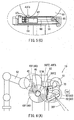
- the first support portion 51H may be driven to rotate the film roll 40 about a horizontal axis, while the mark detection device 92 may detect the position of the mark MK put on the film leading end 40a of the film 40F of the film roll 40. Based on the information regarding the position of the mark MK, the rotation of the film roll 40 may be stopped at a position where the film leading end 40FA is oriented in a predetermined direction (more specifically, a position where the film leading end 40FA is at a lowermost position of the film roll 40). Then, the first arm 51 may transfer the film roll 40 to a position above the tape attaching device 94 while keeping the first support portion 51H to be oriented in the horizontal direction.
- the film roll 40 may be moved to press a film attaching portion 40FS (at one of the side edges with respect to the widthwise direction of the film leading end 40FA) against the block 97 and the claw 97a fixedly attached thereto, so that the block 97 and the claw 97a move along the rod 98 while the double-faced adhesive tape 96 is attached to the front surface of the film leading end 40FA.
- the film attaching portion 40FS may be a portion intended to contact the side edge 30FS of the film terminal end 30FZ of the film 30F and may be positioned less than the distance L from the side edge in the widthwise direction.
- the robot 50 may operate the first arm 51 to move the film roll 40 rearward in a parallel translation manner as shown in FIG 6(A) , while the first support portion 51H is rotated to a position where the double-faced adhesive tape 96 attached to the films leading end 40FA faces the flat surface portion 72A.
- the film leading end 40FA is brought to contact the film terminal end 30FZ of the film 30F held by the film suction portion 74 so as to press the double-faced adhesive tape 96 of the film leading end 40FA against the flat surface portion 72A with the film terminal end 30FZ interposed between the double-fáced adhesive tape 96 and the flat surface portion 72A.
- the film 30F and the film 40F can be connected to each other.
- the double-faced adhesive tape 96 is pressed against the film terminal end 30FZ of the film 30F, a part of the glue applied to the back surface of the film terminal end 30FZ may be pressed against the film leading end 40FA. Therefore, the film 30F and the film 40F are connected with each other through their entire lengths in the widthwise direction by the glue and the double-faced adhesive tape 96.
- the film roll 40 may be moved in a parallel translation manner from the connecting position for connecting the films 30F and the film 40F by the double-faced adhesive tape 96 to the set position spaced obliquely rearward and upward from the connecting position.
- the adhesive force of the double-faced adhesive tape 96 may be larger than that of the glue, the film leading end 40FA adhered to the circumferential surface of the film roll 40 may be separated from the circumferential surface, while the connecting state between the film 30F and the film 40F are kept by the double-faced adhesive tape 96.
- the film 40F of the film roll 40 moved from the connecting position to the set position by the first arm 51 may be permitted to be unwound from the film roll 40.
- the film roll 40 After reaching the set position, the film roll 40 may be fixed at the set position. In this way, the operation for automatically exchanging the film roll 30 with the film roll 40 and the operation for automatically connecting the film 30F and the film 40F may be completed.
- the film processing method and the film processing system usable with the horizontal form-fill packaging machine 10 may have the following advantages:
- the first support portion 51H may serve as a transfer device for transferring the film rolls 30 and 40 and also serve as a film roll support device for supplying the film 30F and 40F to the film feeding section 80. Therefore, it is possible to connect the film 30F and 40F without need of a plurality of film roll support devices in addition to the transfer device as required in the conventional technique. Therefore, it may be possible to achieve a greater possibility in design, such as a spatial layout and to decrease the number of components. In addition, because it is not necessary to use guide rollers that are necessary in the conventional technique for guiding the films 30F and 40F, the construction of the film feeding section 80 can be further simplified.
- the film 30F may be rewound to the film roll 30 while the film 30F is pressed and squeezed against the outer circumferential surface of the film roll 30, and thereafter, the leading end of the rewound film 30F may be adhered to the outer circumferential surface of the film roll 30 by the glue. Therefore, the rewound state of the film 30F can be properly maintained without being loosened even after the film roll 30 has been removed from the first support portion 51. Hence, if the film roll 30 is used again, the film roll 30 can be transferred by the robot 50 without causing the film to be loosened during transferring. For this reason, the robot 50 can automatically connect the film 30F and the film 40F to be exchanged with the film 30F without misregistration between the films.
- the cutting edge of cutter 222A may move into the space 76 between the film suction portion 74 and the film receiving portion 78 so as to cut through the substantially central portion the tensioned film 30F and to thereafter cut the film 30F by a length corresponding to a substantially half the width of the film 30F, and after that, the cutting edge of the cutter 222B may move into the substantially central portion of the film 30F and may thereafter cut the film 30F by a length corresponding to the remaining half of the width of the film 30F. Therefore, the film 30F can be neatly cut along a straight line in the widthwise direction. In addition, it is possible to reduce the risk of damages to the cutting edges of the cutters 222A and 222B.
- the film roll 40 may be moved to press the film attaching portion 40FS against the block 97 and the claw 97a, so that the double-faced adhesive tape 96 is attached to the front surface of the film leading end 40FA so as to extend from a position spaced proximal to the film attaching portion 40FS (i.e., a position spaced from the side edge by the distance L) toward the opposite side edge away from the film attaching portion 40FS in the widthwise direction.
- the double-faced adhesive tape 96 may be neatly attach to the film leading end 40FA at an appropriate position along a straight line in the widthwise direction. This may avoid the film leading end 40FA from turning up and down from the film roll 40, which may occur in the case that the double-faced adhesive tape 96 is attached starting from the side edge of the film 40F.
- the above teachings may be applied to any other packaging machines in which a film is unwound from a film roll.
- the material of the film may not be limited and may be resin, paper, metal or any other material.
- the connecting device may not be limited to the double faced adhesive tape 96 that is a drying and solidifying type adhesive.
- drying and solidifying type adhesive is used to mean an adhesive that contains, an adhesive material dissolved in water or solvent.
- the adhesive material may be solidified after evaporation of water or solvent.
- the drying and solidifying type adhesive may include glue other than the adhesive tape.
- the connection device may maintain a connecting state between the films even after the film leading end adhered to the outer circumferential surface of the film roll has been separated from the outer circumferential surface during the transfer of the film roll to the storing position.
- any other drying and solidifying type adhesive such as a double-faced adhesive tape can be used. It may be also possible to use a chemical reaction type adhesive or any other type of adhesive.
- the double-faced adhesive tape 96 is attached to the film leading end 40FA for connection with the film terminal end 30FZ, it may be possible to attach the adhesive tape 96 to the film terminal end 30FZ held by the film holding device, and thereafter the film leading end 40FA may be pressed against the film terminal end 30FZ for connection by the double-faced adhesive tape 96. Also by this arrangement, the films 30F and 40F can be automatically connected.
- a supply device such as a conveyor for automatically supplying a new film roll to the first set section at each time the robot takes the film roll from the first set section.
- a discharge device such as a conveyor for automatically discharge the film roll to the outside of the first set section at each time the film roll is set at the first set section by the robot.
- the fist set section is configured to store the film rolls such that the axes of the film rolls are oriented in the vertical direction, it may be possible to store the film rolls with their axes oriented in the horizontal direction or any other direction as long as the film rolls are within the movable range of the robot. This may be also applied to the second set section.
- first support portion 51H is configured to support the film rolls and the second support portion 52H is configured to support the cutting tools in the above embodiment, the first support portion 51H may be configured to support the cutting tools and the second support portion 52H may be configured to support the film rolls.
- the robot 50 may include thee or more arms for performing film connection operations for a plurality of packaging machines that are suitably arranged.
- the robot 50 is provided as a separated device from the packaging machine, it may be possible to mount the first and second arms 51 and 52 to a machine body or any of the components of the packaging machine, so that a robot body supporting these arms can be eliminated.
- the fist support portion 51H supports the film roll so as to allow rotation or the film roll during the packaging operation
- the first support portion may be rotatably driven to assist the film to be unwound from the film roll.
- the marking device 212 may be a seal attaching device that can attach a seal serving as the mark MK to the back surface of the film 30F.
- the mark detection device 92 may detect the position of the mark MK, for example based on image information obtained by an imaging device, such as a camera. It may be also possible to position the first support portion relative to the film roll and to position the second support portion relative to the first and second tools based on image information obtained by an imaging device(s).
- the first set section 100 may be separated into a plurality of set sections.
- the old film roll transferred by the first support portion may be stored in a different set section from that storing the new film roll to be used in the future.
- the film holding device may not be limited to the suction portion 74.
- plates or claws movable toward and away from the tensioned film 30F in the widthwise direction may be disposed at the connection section 70.
- the plates or claws may be coupled to an actuator that is operable to move the plates or claws for holding the film from opposite sides according to a command signal from the controller during the film connecting operation.
- the cutters 222A and 222B serving as a cutting device are moved by the second support portion for cutting the film 30F
- the cutters 222A and 222B may be mounted to a different member from the second support portion.
- the cutters 222A and 222B may be disposed at the connection operation section 70 and may be coupled to an actuator(s). According to a command signal transmitted from the control device to the actuator(s), the cutters 222A and 222B may automatically move into and out of the space 76 formed between the film suction portion 74 and the film receiving portion 78 for cutting the film 30F.
- the flat surface portion 78A of the film receiving portion 78 may be replaced with any other surface portion that does not have a flat surface.
- variously shaped surface portions may be used as long as they allow the film to be tensioned in the feeding direction and in the widthwise direction.
- a suitable roller device such as a set of parallel rollers movable relative to each other to change a distance(s) therebetween, may be arranged in the film feeding section 80 at a position between the connecting operation section 70 and the feeding device 81.
- a part of the film wound around the rollers of the roller device may be drawn for continuously supplying the film to the former. This may allow a continuous packaging operation or minimize the time necessary for stopping the supply of the film to the former.
Landscapes
- Replacement Of Web Rolls (AREA)
Claims (9)
- Filmbearbeitungsverfahren zum automatischen Verbinden eines Films (30F) einer ersten Filmrolle (30) mit einem Film (40F) einer zweiten Filmrolle (40), die gegen die erste Filmrolle (30) in einer Verpackungsmaschine (10) ausgewechselt werden soll, umfassend:Halten des Films (30F) der ersten Filmrolle (30) in einer Halteposition durch eine Haltevorrichtung (74), während die ersten Filmrolle (30) von einem Roboter (50) abgestützt wird, und der Film (30F) der Filmrolle (30) von der ersten Filmrolle (30) abgewickelt wird und sich in einem gespannten Zustand zu einer Formvorrichtung (20) erstreckt;Betreiben einer Schneidvorrichtung (222A, 222B) zum automatischen Schneiden des Films (30F) der ersten Filmrolle (30) an einer Schneidposition auf einer stromaufwärtigen Seite der Halteposition in Bezug auf eine Einführungsrichtung zur Formvorrichtung (20), während der Film (30F) von der Haltevorrichtung (74) gehalten wird;Betreiben des Roboters (50) zum Bewegen der ersten Filmrolle (30) die den Film (30F), der automatisch geschnitten wurde, aufweist, zu einem Lagerbereich (100), sodass die erste Filmrolle (30) an dem Lagerbereich (100) gelagert wird, wobei der Lagerbereich (100) innerhalb eines Bewegungsbereichs des Roboters (50) angeordnet ist und die zweite Filmrolle (40) lagert;
Betreiben des Roboters (50) zum Herausnehmen der zweiten Filmrolle (40) aus dem Lagerbereich (100), drehbares Abstützen der zweiten Filmrolle (40), und Bewegen der zweiten Filmrolle (40) zu einer Verbindungsposition, wo sich ein vorderes Filmende (40FA) eines Films (40F) der zweiten Filmrolle (40) mit einem hinteren Filmende (30FZ) des Films (30F) der ersten Filmrolle (30) überlappt, welches an einer stromabwärtigen Seite der Schneidposition geblieben ist und von der Haltevorrichtung (74) gehalten wird;Verbinden des vorderen Filmendes (40FA) des Films (40F) der zweiten Filmrolle (40) mit dem hinteren Filmende (30FZ) des Films (30F) der ersten Filmrolle (30) durch eine Verbindungsvorrichtung (96), wobei sich gleichzeitig das vordere Filmende (40FA) mit dem hinteren Filmende (30FZ) überlappt oder nachdem sich das vordere Filmende (40FA) mit dem hinteren Filmende (30FZ) überlappt hat;gekennzeichnet dadurch, dassder Roboter (50) nach dem Verbinden des Films (30F, 40F) durch die Verbindungsvorrichtung (96)zum Bewegen der zweiten Filmrolle (40) von der Verbindungsposition zu einer eingestellten Position betrieben wird, die von der Verbindungsposition beabstandet ist, sodass der Film (40F) der zweiten Filmrolle (40) zum Zuführen zu der Formvorrichtung (20) gespannt wird. - Filmbearbeitungsverfahren nach Anspruch 1, ferner umfassend:Positionieren der zweiten Filmrolle (40), die aus dem Lagerbereich (100) genommen wurde, an einem Verbindungsherstellungsabschnitt (90) durch den Betrieb eines Roboters (50) vor dem Bewegen zur Verbindungsposition, wobei der Verbindungsherstellungsabschnitt (90) innerhalb eines Bewegungsbereichs des Roboters (50) angeordnet ist;Verwenden eines Klebstoffes (96) als Verbindungsvorrichtung und Aufbringen des Klebstoffs (96) auf das vordere Filmende (40FA) des Films (40F) der zweiten Filmrolle (40), die am Verbindungsherstellungsabschnitt (90) positioniert ist, sodass das vordere Filmende (40FA) des Films (40F) der zweiten Filmrolle (40) und das hintere Filmende (30FZ) des Films (30F) der ersten Filmrolle (30) durch den Klebstoff (96) miteinander verbunden werden und sich gleichzeitig das vordere Filmende (40FA) mit dem hinteren Filmende (30FZ) als Ergebnis der Bewegung der zweiten Filmrolle (40) zu der Verbindungsposition von dem Verbindungsherstellungsabschnitt (90) überlappt.
- Filmbearbeitungsverfahren nach Anspruch 1, ferner umfassend:Befestigen des vorderen Filmendes (40FA) der zweiten Filmrolle (40F) mit einer Umfangsoberfläche der zweiten Filmrolle (40) über einen Klebstoff (214), bevor die zweite Filmrolle (40) in dem Lagerbereich (100) gelagert wird; undBewirken, dass das vordere Filmende (40FA) der zweiten Filmrolle (40FA) von der Umfangsoberfläche der zweiten Filmrolle (40FA) gegen eine Klebekraft des Klebstoffs (214) getrennt wird, während sich die zweite Filmrolle (40FA) von der Verbindungsposition zur eingestellten Position bewegt;wobei die Klebekraft des Klebstoffs (214) kleiner als eine Verbindungskraft zwischen dem vorderen Filmende (40FA) der zweiten Filmrolle (40) und dem hinteren Filmende (30FZ) der ersten Filmrolle (30) ist, die durch die Verbindungsvorrichtung (96) verbunden werden.
- Filmbearbeitungsverfahren nach Anspruch 1, ferner umfassend:Auftragen eines ersten Klebstoffs (214) auf einen der Seitenränder in Bezug auf die Breitenrichtung eines Teils des Films (30F) der ersten Filmrolle (30), die von der Haltevorrichtung (74) gehalten wird, bevor der Film (30F) der ersten Filmrolle (30) an der Schneidposition durch die Schneidvorrichtung (222A, 222B) geschnitten wird, wobei, nachdem der Film (30F) der ersten Filmrolle (30) geschnitten wurde, der Teil des Films (30F) das hintere Filmende (30FZ) der ersten Filmrolle (30) bildet und von der Haltevorrichtung (74) gehalten wird; undVerwenden eines zweiten Klebstoffes (96) als Verbindungsvorrichtung und Aufbringen des zweiten Klebstoffs (96) auf das vordere Filmende (40FA) des Films (40F) der zweiten Filmrolle (40) vor dem Bewegen der zweiten Filmrolle (40) zur Verbindungsposition, sodass das vordere Filmende (40FA) des Films (40F) der zweiten Filmrolle (40) und das hintere Filmende (30FZ) des Films (30F) der ersten Filmrolle (30) durch den ersten Klebstoff (214) und den zweiten Klebstoff (96) miteinander verbunden werden und sich gleichzeitig das vordere Filmende (40FA) mit dem hinteren Filmende (30FZ) als Ergebnis der Bewegung der zweiten Filmrolle (40) zur Verbindungsposition überlappt, nachdem der zweite Klebstoff (96) auf die zweite Filmrolle (40) aufgebracht wurde;wobei sich der zweite Klebstoff (96) von einer Position, die proximal zu einer Filmbefestigungsposition in Breitenrichtung weg von der Filmbefestigungsposition erstreckt; undwobei die Filmbefestigungsposition eingestellt wird, um einer Position des ersten Klebstoffs (214) zu entsprechen , der auf den Film (30F) der ersten Filmrolle (30) aufgebracht wird.
- Filmbearbeitungsverfahren nach Anspruch 1, wobei:der Roboter (50) einen ersten Arm (51) und einen zweiten Arm (52) einschließt, die jeweils einen Tragabschnitt (51H, 52H) aufweisen;der Tragabschnitt (51H) des ersten Arms (51) zum drehbaren Tragen der zweiten Filmrolle (40) konfiguriert ist; undder Tragabschnitt (52H) des zweiten Arms (52) zum Tragen der Schneidvorrichtung (222A, 222B) konfiguriert ist.
- Filmbearbeitungssystem zum automatischen Verbinden eines Films (30F) einer ersten Filmrolle (30) und eines Films (40F) einer zweiten Filmrolle (40), die mit der ersten Filmrolle (30) in einer Verpackungsmaschine (10) ausgewechselt werden soll, umfassend:einen Roboter (50), der zum Betreiben gemäß eines Filmrollen-Austauschbefehls konfiguriert ist; eine Schneidvorrichtung (222A, 222B), die zum automatischen Schneiden des Films (30F) der ersten Filmrolle (30) an einer Schneidposition konfiguriert ist, wenn der Film (30F) der ersten Filmrolle (30) von der ersten Filmrolle (30) abgewickelt ist, um sich zu einer Formvorrichtung (20) in gespannten Zustand zu erstrecken, während die erste Filmrolle (30) von dem Roboter (50) abgestützt wird;eine Filmhaltevorrichtung (74), die zum Halten eines hinteren Filmendes (30FZ) des Films (30F) der ersten Filmrolle (30) an einer Halteposition auf einer stromabwärtigen Seite der Schneidposition in Bezug auf die Einführungsrichtung zu der Formvorrichtung (20) konfiguriert ist, wenn der Film (30F) von der Schneidvorrichtung (222A, 222B) geschnitten wird;einen Lagerbereich (100), der innerhalb eines Bewegungsbereichs des Roboters (50) angeordnet ist und zum Lagern der ersten Filmrolle (30) und der zweiten Filmrolle (40) konfiguriert ist,wobei der Roboter (50) konfiguriert ist, die erste Filmrolle (30) zum Lagerbereich (100) zu bewegen, nachdem der Film (30F) geschnitten wurde, so dass die erste Filmrolle (30) an dem Lagerbereich (100) gelagert wird; undwobei der Roboter (50) ferner zum Herausnehmen der zweiten Filmrolle (40) aus dem Lagerbereich (100), zum Überführen der zweiten Filmrolle (40) zu einer Verbindungsposition, zum drehbaren Abstützen der zweiten Filmrolle (40) an der Verbindungsposition und zum Bewegen eines vorderen Filmendes (40FA) der zweiten Filmrolle (40) konfiguriert ist, sodass das vordere Filmende (40FA) mit dem hinteren Filmende (30FZ) des Films (30F) der ersten Filmrolle (30), die nach dem Schneiden übrig geblieben ist und von der Filmhaltevorrichtung (74) gehalten wird, in Kontakt tritt;eine Verbindungsvorrichtung (96), die zum Verbinden des vorderen Filmendes (40FA) der zweiten Filmrolle (40) mit dem hinteren Filmende (30FZ) des Films (30F) der ersten Filmrolle (30) konfiguriert ist, wobei sich gleichzeitig das vordere Filmende (40FA) mit dem hinteren Filmende (30FZ) überlappt oder nachdem sich das vordere Filmende (40FZ) mit dem hinteren Filmende (30FA) überlappt hat;dadurch gekennzeichnet, dass der Roboter (50) ferner konfiguriert ist, um die zweite Filmrolle (40) von der Verbindungsposition zu einer eingestellten Position zu überführen, nachdem die Filme (30F, 40F) von der Verbindungsvorrichtung (96) verbunden worden sind, sodass der Film (40F) der zweiten Filmrolle (40) zum Zuführen zu der Formvorrichtung (20) gespannt ist.
- Filmbearbeitungssystem nach Anspruch 6, ferner umfassend eine Filmaufnahmevorrichtung (98), die an einer Position auf einer stromaufwärtigen Seite in Bezug auf die Einführungsrichtung der Filmhaltevorrichtung (74) angeordnet ist und zum Abstützen des Films (30F) der ersten Filmrolle (30) in gespanntem Zustand konfiguriert ist, wobei ein Raum (76) zwischen der Filmaufnahmevorrichtung (98) und der Filmhaltevorrichtung (74) definiert wird, um einem Schneidwerkzeug der Schneidvorrichtung (222A, 222B) zu ermöglichen, sich in den Raum zu bewegen.
- Filmbearbeitungssystem nach Anspruch 6 oder 7, wobei die Filmhalteeinrichtung eine Filmansaugvorrichtung (74) ist.
- Filmbearbeitungssystem nach einem der Ansprüche 6 bis 8, ferner umfassend eine Filmeinfallwinkel-Einstellvorrichtung (81), die entlang einer Filmeinführbahn zwischen der Formvorrichtung (20) und der ersten Filmrolle (30) oder der zweiten Filmrolle (40) angeordnet ist und zum Einstellen eines Einfallwinkels des Films (30F, 40F) in Bezug auf die Formvorrichtung (20) konfiguriert ist, wobei die Filmeinfallwinkel-Einstellvorrichtung (81) eine einzige Führungsrolle (83) umfasst, die zum Eingreifen in den Film (30F, 40F) konfiguriert ist.
Applications Claiming Priority (1)
| Application Number | Priority Date | Filing Date | Title |
|---|---|---|---|
| JP2014053540A JP5894623B2 (ja) | 2014-03-17 | 2014-03-17 | 包装機におけるフィルム処理方法及びその装置 |
Publications (2)
| Publication Number | Publication Date |
|---|---|
| EP2933211A1 EP2933211A1 (de) | 2015-10-21 |
| EP2933211B1 true EP2933211B1 (de) | 2016-11-30 |
Family
ID=52823440
Family Applications (1)
| Application Number | Title | Priority Date | Filing Date |
|---|---|---|---|
| EP15157842.4A Not-in-force EP2933211B1 (de) | 2014-03-17 | 2015-03-05 | Verfahren und systeme zum bearbeiten von filmen in verpackungsmaschinen |
Country Status (3)
| Country | Link |
|---|---|
| US (1) | US10059550B2 (de) |
| EP (1) | EP2933211B1 (de) |
| JP (1) | JP5894623B2 (de) |
Families Citing this family (11)
| Publication number | Priority date | Publication date | Assignee | Title |
|---|---|---|---|---|
| JP5894623B2 (ja) * | 2014-03-17 | 2016-03-30 | 株式会社フジキカイ | 包装機におけるフィルム処理方法及びその装置 |
| DE102016103272A1 (de) * | 2016-02-24 | 2017-08-24 | Leonhard Kurz Stiftung & Co. Kg | Verfahren und Vorrichtung zum Verbinden zweier Folienbahnen und derart erhältliche Folienbahn |
| KR101896320B1 (ko) * | 2016-03-04 | 2018-09-07 | 기아자동차 주식회사 | 연료전지의 gdl 커팅시스템 |
| JP6594836B2 (ja) | 2016-09-29 | 2019-10-23 | 株式会社フジキカイ | 横形製袋充填機におけるフィルム供給装置 |
| JP6629702B2 (ja) * | 2016-09-30 | 2020-01-15 | 株式会社フジキカイ | 製函装置 |
| US11352230B2 (en) | 2016-11-02 | 2022-06-07 | Zuiko Corporation | Sheet-feeding system and sheet-feeding method |
| DK3771390T3 (da) * | 2019-08-02 | 2021-12-13 | Cws Int Gmbh | Fremgangsmåde og indretning til detektering af et påfyldningsniveau i en papirdispenser |
| CN114309991B (zh) * | 2022-01-21 | 2024-05-07 | 深圳市易安锐自动化设备有限公司 | 激光自动切割控制系统及其控制方法 |
| EP4321462A4 (de) * | 2022-07-01 | 2025-04-16 | Wuxi Lead Intelligent Equipment Co., Ltd. | Automatische rollenwechselvorrichtung |
| CN116081361A (zh) * | 2022-09-09 | 2023-05-09 | 无锡先导智能装备股份有限公司 | 一种换卷设备 |
| WO2025216604A1 (ko) * | 2024-04-08 | 2025-10-16 | 주식회사 에이아이로보틱스 | 자율주행 방식의 필름 롤 교체 및 연결부착 로봇 |
Family Cites Families (32)
| Publication number | Priority date | Publication date | Assignee | Title |
|---|---|---|---|---|
| DE1250709B (de) * | 1961-07-08 | 1967-09-21 | ||
| US3317153A (en) * | 1966-03-07 | 1967-05-02 | Miehle Goss Dexter Inc | Digital control system for printing presses or the like |
| US3409242A (en) * | 1965-11-11 | 1968-11-05 | Hamada Printing Press | Apparatus for detecting the diameter of a rolled sheet |
| US3771737A (en) * | 1973-03-12 | 1973-11-13 | Arcata Graphics | Paster control target |
| US3891158A (en) * | 1973-07-13 | 1975-06-24 | Du Pont | Method and apparatus for splicing a standby web to a running web |
| JPS5752301B2 (de) * | 1974-06-01 | 1982-11-06 | ||
| JPS5931244A (ja) * | 1982-08-09 | 1984-02-20 | Dainippon Printing Co Ltd | 給紙装置の紙継ぎ方法 |
| US4575017A (en) * | 1984-06-04 | 1986-03-11 | Essex Group, Inc. | Paster tab and method of use |
| US4575016A (en) * | 1984-06-04 | 1986-03-11 | Essex Group, Inc. | Continuous ribbon feed method and system |
| US4934624A (en) * | 1986-01-21 | 1990-06-19 | Philip Morris, Inc. | A robotic hand |
| DE3723600A1 (de) * | 1987-07-17 | 1989-01-26 | Voith Gmbh J M | Abwickelvorrichtung fuer papier- oder kartonbahn |
| DE4000745A1 (de) * | 1990-01-12 | 1991-07-18 | Roland Man Druckmasch | Rollenwechselvorrichtung fuer eine druckmaschine |
| US5337969A (en) * | 1992-08-26 | 1994-08-16 | Martin Automatic, Inc. | Flying paster |
| US5849123A (en) * | 1995-12-20 | 1998-12-15 | Eastman Kodak Company | Apparatus and method for aligning webs |
| US5692698A (en) * | 1996-02-05 | 1997-12-02 | Forbes; Thomas J. | Web feeding and transition assembly |
| US5935361A (en) * | 1996-07-17 | 1999-08-10 | Fuji Photo Film Co., Ltd. | Web splicing preparation method and apparatus |
| JPH10119928A (ja) * | 1996-08-30 | 1998-05-12 | Toyo Jidoki Co Ltd | 原反の連続供給装置 |
| JP2000264509A (ja) * | 1999-03-16 | 2000-09-26 | Nippon Jido Seiki Kk | ウェブの自働接合装置 |
| US6820837B2 (en) * | 2002-12-20 | 2004-11-23 | Kimberly-Clark Worldwide, Inc. | Unwind system with flying-splice roll changing |
| ITFI20030065A1 (it) * | 2003-03-13 | 2004-09-14 | Perini Fabio Spa | Dispositivo svolgitore per bobine di materiale nastriforme con organi di accumulo temporaneo del materiale svolto nella fase di cambio bobina e relativo metodo |
| JP4480383B2 (ja) * | 2003-11-05 | 2010-06-16 | 澁谷工業株式会社 | 帯状物引出装置 |
| JP4089591B2 (ja) * | 2003-11-05 | 2008-05-28 | 澁谷工業株式会社 | ロール装填装置 |
| JP2005231789A (ja) * | 2004-02-18 | 2005-09-02 | Fuji Photo Film Co Ltd | パンケーキ交換用ロボット。 |
| JP2007320733A (ja) * | 2006-06-02 | 2007-12-13 | Komori Corp | 帯状体連続供給方法及び装置 |
| US7980504B2 (en) * | 2009-04-17 | 2011-07-19 | C.G. Bretting Manufacturing Co., Inc. | Automated unwind system with auto-splice |
| US9566193B2 (en) * | 2011-02-25 | 2017-02-14 | Curt G. Joa, Inc. | Methods and apparatus for forming disposable products at high speeds with small machine footprint |
| JP5901477B2 (ja) | 2012-09-10 | 2016-04-13 | 東京エレクトロン株式会社 | 塗布、現像装置 |
| JP5894623B2 (ja) * | 2014-03-17 | 2016-03-30 | 株式会社フジキカイ | 包装機におけるフィルム処理方法及びその装置 |
| US9919887B2 (en) * | 2014-08-28 | 2018-03-20 | The Procter & Gamble Company | Web material unwind stand |
| US9926160B2 (en) * | 2014-08-28 | 2018-03-27 | The Procter & Gamble Company | Robotic unwind stand |
| US9969587B2 (en) * | 2014-08-28 | 2018-05-15 | The Procter & Gamble Company | Web material unwind apparatus |
| DE102015218321A1 (de) * | 2015-09-24 | 2017-03-30 | Bhs Corrugated Maschinen- Und Anlagenbau Gmbh | Splicevorrichtung |
-
2014
- 2014-03-17 JP JP2014053540A patent/JP5894623B2/ja not_active Expired - Fee Related
-
2015
- 2015-03-05 US US14/639,364 patent/US10059550B2/en active Active
- 2015-03-05 EP EP15157842.4A patent/EP2933211B1/de not_active Not-in-force
Non-Patent Citations (1)
| Title |
|---|
| None * |
Also Published As
| Publication number | Publication date |
|---|---|
| JP5894623B2 (ja) | 2016-03-30 |
| US20150259168A1 (en) | 2015-09-17 |
| JP2015174683A (ja) | 2015-10-05 |
| US10059550B2 (en) | 2018-08-28 |
| EP2933211A1 (de) | 2015-10-21 |
Similar Documents
| Publication | Publication Date | Title |
|---|---|---|
| EP2933211B1 (de) | Verfahren und systeme zum bearbeiten von filmen in verpackungsmaschinen | |
| KR101012583B1 (ko) | 필름 공급 장치 및 그것을 갖춘 포장 장치 | |
| US10676303B2 (en) | Method and apparatus for supplying, staging and for replacing rolls with flat material and/or film material wound thereonto | |
| CN111003275B (zh) | 制袋包装机 | |
| US11046468B2 (en) | Bag-making and packaging machine | |
| JP5695466B2 (ja) | シート貼付装置および貼付方法 | |
| US11332336B2 (en) | Feed for plastic-wrapping | |
| JP2019034852A (ja) | 巻き出しアセンブリ、および巻き出しアセンブリにリールを自動的に装填するための方法 | |
| CN111542477A (zh) | 用于将标签施加到香烟包装件上的方法和设备 | |
| JP5658856B2 (ja) | 模様合わせを可能にする紙つなぎ方法及び装置 | |
| JP6146867B2 (ja) | 包装機における原反ロールのフィルム処理方法およびその装置 | |
| CN1288056C (zh) | 条带输送装置及方法 | |
| JP7116974B2 (ja) | 包装機における紙継ぎ方法及び装置 | |
| CA3233530C (en) | Splicing apparatus and method for a paperboard protective corner manufacturing system | |
| JP6114216B2 (ja) | 包装機における原反ロールのフィルム接続方法 | |
| KR20170012004A (ko) | 자동 랜덤 랩핑 시스템 | |
| JP7195899B2 (ja) | フィルム接続装置 | |
| JP7649049B2 (ja) | 包材ロールの自動供給装置 | |
| JP7576339B2 (ja) | 包材ロールの自動供給装置 | |
| JP7401900B2 (ja) | フィルム供給装置及びフィルム供給装置を備えた製袋包装機 | |
| JP3853335B2 (ja) | 繰出しフィルムの端部接合装置 | |
| JPH07101610A (ja) | 両面粘着テープの自動供給取付装置 | |
| JP2002265109A (ja) | シートの供給装置 | |
| JP2016020234A (ja) | 連続帯状体の繋ぎ装置 | |
| US20180334347A1 (en) | Auto film splicing assembly with film roll positioner |
Legal Events
| Date | Code | Title | Description |
|---|---|---|---|
| PUAI | Public reference made under article 153(3) epc to a published international application that has entered the european phase |
Free format text: ORIGINAL CODE: 0009012 |
|
| AK | Designated contracting states |
Kind code of ref document: A1 Designated state(s): AL AT BE BG CH CY CZ DE DK EE ES FI FR GB GR HR HU IE IS IT LI LT LU LV MC MK MT NL NO PL PT RO RS SE SI SK SM TR |
|
| AX | Request for extension of the european patent |
Extension state: BA ME |
|
| 17P | Request for examination filed |
Effective date: 20151110 |
|
| RBV | Designated contracting states (corrected) |
Designated state(s): AL AT BE BG CH CY CZ DE DK EE ES FI FR GB GR HR HU IE IS IT LI LT LU LV MC MK MT NL NO PL PT RO RS SE SI SK SM TR |
|
| GRAP | Despatch of communication of intention to grant a patent |
Free format text: ORIGINAL CODE: EPIDOSNIGR1 |
|
| INTG | Intention to grant announced |
Effective date: 20160420 |
|
| GRAJ | Information related to disapproval of communication of intention to grant by the applicant or resumption of examination proceedings by the epo deleted |
Free format text: ORIGINAL CODE: EPIDOSDIGR1 |
|
| INTC | Intention to grant announced (deleted) | ||
| GRAS | Grant fee paid |
Free format text: ORIGINAL CODE: EPIDOSNIGR3 |
|
| GRAP | Despatch of communication of intention to grant a patent |
Free format text: ORIGINAL CODE: EPIDOSNIGR1 |
|
| INTG | Intention to grant announced |
Effective date: 20160923 |
|
| GRAA | (expected) grant |
Free format text: ORIGINAL CODE: 0009210 |
|
| AK | Designated contracting states |
Kind code of ref document: B1 Designated state(s): AL AT BE BG CH CY CZ DE DK EE ES FI FR GB GR HR HU IE IS IT LI LT LU LV MC MK MT NL NO PL PT RO RS SE SI SK SM TR |
|
| REG | Reference to a national code |
Ref country code: CH Ref legal event code: EP Ref country code: GB Ref legal event code: FG4D |
|
| REG | Reference to a national code |
Ref country code: AT Ref legal event code: REF Ref document number: 849579 Country of ref document: AT Kind code of ref document: T Effective date: 20161215 |
|
| REG | Reference to a national code |
Ref country code: IE Ref legal event code: FG4D |
|
| REG | Reference to a national code |
Ref country code: DE Ref legal event code: R096 Ref document number: 602015000831 Country of ref document: DE |
|
| PG25 | Lapsed in a contracting state [announced via postgrant information from national office to epo] |
Ref country code: LV Free format text: LAPSE BECAUSE OF FAILURE TO SUBMIT A TRANSLATION OF THE DESCRIPTION OR TO PAY THE FEE WITHIN THE PRESCRIBED TIME-LIMIT Effective date: 20161130 |
|
| REG | Reference to a national code |
Ref country code: LT Ref legal event code: MG4D |
|
| REG | Reference to a national code |
Ref country code: NL Ref legal event code: MP Effective date: 20161130 |
|
| REG | Reference to a national code |
Ref country code: AT Ref legal event code: MK05 Ref document number: 849579 Country of ref document: AT Kind code of ref document: T Effective date: 20161130 |
|
| PG25 | Lapsed in a contracting state [announced via postgrant information from national office to epo] |
Ref country code: LT Free format text: LAPSE BECAUSE OF FAILURE TO SUBMIT A TRANSLATION OF THE DESCRIPTION OR TO PAY THE FEE WITHIN THE PRESCRIBED TIME-LIMIT Effective date: 20161130 Ref country code: NO Free format text: LAPSE BECAUSE OF FAILURE TO SUBMIT A TRANSLATION OF THE DESCRIPTION OR TO PAY THE FEE WITHIN THE PRESCRIBED TIME-LIMIT Effective date: 20170228 Ref country code: GR Free format text: LAPSE BECAUSE OF FAILURE TO SUBMIT A TRANSLATION OF THE DESCRIPTION OR TO PAY THE FEE WITHIN THE PRESCRIBED TIME-LIMIT Effective date: 20170301 Ref country code: SE Free format text: LAPSE BECAUSE OF FAILURE TO SUBMIT A TRANSLATION OF THE DESCRIPTION OR TO PAY THE FEE WITHIN THE PRESCRIBED TIME-LIMIT Effective date: 20161130 |
|
| PG25 | Lapsed in a contracting state [announced via postgrant information from national office to epo] |
Ref country code: PT Free format text: LAPSE BECAUSE OF FAILURE TO SUBMIT A TRANSLATION OF THE DESCRIPTION OR TO PAY THE FEE WITHIN THE PRESCRIBED TIME-LIMIT Effective date: 20170330 Ref country code: ES Free format text: LAPSE BECAUSE OF FAILURE TO SUBMIT A TRANSLATION OF THE DESCRIPTION OR TO PAY THE FEE WITHIN THE PRESCRIBED TIME-LIMIT Effective date: 20161130 Ref country code: AT Free format text: LAPSE BECAUSE OF FAILURE TO SUBMIT A TRANSLATION OF THE DESCRIPTION OR TO PAY THE FEE WITHIN THE PRESCRIBED TIME-LIMIT Effective date: 20161130 Ref country code: FI Free format text: LAPSE BECAUSE OF FAILURE TO SUBMIT A TRANSLATION OF THE DESCRIPTION OR TO PAY THE FEE WITHIN THE PRESCRIBED TIME-LIMIT Effective date: 20161130 Ref country code: RS Free format text: LAPSE BECAUSE OF FAILURE TO SUBMIT A TRANSLATION OF THE DESCRIPTION OR TO PAY THE FEE WITHIN THE PRESCRIBED TIME-LIMIT Effective date: 20161130 Ref country code: HR Free format text: LAPSE BECAUSE OF FAILURE TO SUBMIT A TRANSLATION OF THE DESCRIPTION OR TO PAY THE FEE WITHIN THE PRESCRIBED TIME-LIMIT Effective date: 20161130 Ref country code: PL Free format text: LAPSE BECAUSE OF FAILURE TO SUBMIT A TRANSLATION OF THE DESCRIPTION OR TO PAY THE FEE WITHIN THE PRESCRIBED TIME-LIMIT Effective date: 20161130 |
|
| PG25 | Lapsed in a contracting state [announced via postgrant information from national office to epo] |
Ref country code: NL Free format text: LAPSE BECAUSE OF FAILURE TO SUBMIT A TRANSLATION OF THE DESCRIPTION OR TO PAY THE FEE WITHIN THE PRESCRIBED TIME-LIMIT Effective date: 20161130 |
|
| PG25 | Lapsed in a contracting state [announced via postgrant information from national office to epo] |
Ref country code: RO Free format text: LAPSE BECAUSE OF FAILURE TO SUBMIT A TRANSLATION OF THE DESCRIPTION OR TO PAY THE FEE WITHIN THE PRESCRIBED TIME-LIMIT Effective date: 20161130 Ref country code: SK Free format text: LAPSE BECAUSE OF FAILURE TO SUBMIT A TRANSLATION OF THE DESCRIPTION OR TO PAY THE FEE WITHIN THE PRESCRIBED TIME-LIMIT Effective date: 20161130 Ref country code: EE Free format text: LAPSE BECAUSE OF FAILURE TO SUBMIT A TRANSLATION OF THE DESCRIPTION OR TO PAY THE FEE WITHIN THE PRESCRIBED TIME-LIMIT Effective date: 20161130 Ref country code: DK Free format text: LAPSE BECAUSE OF FAILURE TO SUBMIT A TRANSLATION OF THE DESCRIPTION OR TO PAY THE FEE WITHIN THE PRESCRIBED TIME-LIMIT Effective date: 20161130 Ref country code: CZ Free format text: LAPSE BECAUSE OF FAILURE TO SUBMIT A TRANSLATION OF THE DESCRIPTION OR TO PAY THE FEE WITHIN THE PRESCRIBED TIME-LIMIT Effective date: 20161130 |
|
| PG25 | Lapsed in a contracting state [announced via postgrant information from national office to epo] |
Ref country code: BG Free format text: LAPSE BECAUSE OF FAILURE TO SUBMIT A TRANSLATION OF THE DESCRIPTION OR TO PAY THE FEE WITHIN THE PRESCRIBED TIME-LIMIT Effective date: 20170228 Ref country code: SM Free format text: LAPSE BECAUSE OF FAILURE TO SUBMIT A TRANSLATION OF THE DESCRIPTION OR TO PAY THE FEE WITHIN THE PRESCRIBED TIME-LIMIT Effective date: 20161130 Ref country code: BE Free format text: LAPSE BECAUSE OF FAILURE TO SUBMIT A TRANSLATION OF THE DESCRIPTION OR TO PAY THE FEE WITHIN THE PRESCRIBED TIME-LIMIT Effective date: 20161130 |
|
| REG | Reference to a national code |
Ref country code: DE Ref legal event code: R097 Ref document number: 602015000831 Country of ref document: DE |
|
| PLBE | No opposition filed within time limit |
Free format text: ORIGINAL CODE: 0009261 |
|
| STAA | Information on the status of an ep patent application or granted ep patent |
Free format text: STATUS: NO OPPOSITION FILED WITHIN TIME LIMIT |
|
| 26N | No opposition filed |
Effective date: 20170831 |
|
| PG25 | Lapsed in a contracting state [announced via postgrant information from national office to epo] |
Ref country code: SI Free format text: LAPSE BECAUSE OF FAILURE TO SUBMIT A TRANSLATION OF THE DESCRIPTION OR TO PAY THE FEE WITHIN THE PRESCRIBED TIME-LIMIT Effective date: 20161130 Ref country code: MC Free format text: LAPSE BECAUSE OF FAILURE TO SUBMIT A TRANSLATION OF THE DESCRIPTION OR TO PAY THE FEE WITHIN THE PRESCRIBED TIME-LIMIT Effective date: 20161130 |
|
| REG | Reference to a national code |
Ref country code: IE Ref legal event code: MM4A |
|
| REG | Reference to a national code |
Ref country code: FR Ref legal event code: ST Effective date: 20171130 |
|
| PG25 | Lapsed in a contracting state [announced via postgrant information from national office to epo] |
Ref country code: LU Free format text: LAPSE BECAUSE OF NON-PAYMENT OF DUE FEES Effective date: 20170305 Ref country code: FR Free format text: LAPSE BECAUSE OF NON-PAYMENT OF DUE FEES Effective date: 20170331 |
|
| PG25 | Lapsed in a contracting state [announced via postgrant information from national office to epo] |
Ref country code: IE Free format text: LAPSE BECAUSE OF NON-PAYMENT OF DUE FEES Effective date: 20170305 |
|
| PG25 | Lapsed in a contracting state [announced via postgrant information from national office to epo] |
Ref country code: MT Free format text: LAPSE BECAUSE OF NON-PAYMENT OF DUE FEES Effective date: 20170305 |
|
| REG | Reference to a national code |
Ref country code: CH Ref legal event code: PL |
|
| PG25 | Lapsed in a contracting state [announced via postgrant information from national office to epo] |
Ref country code: LI Free format text: LAPSE BECAUSE OF NON-PAYMENT OF DUE FEES Effective date: 20180331 Ref country code: CH Free format text: LAPSE BECAUSE OF NON-PAYMENT OF DUE FEES Effective date: 20180331 |
|
| PG25 | Lapsed in a contracting state [announced via postgrant information from national office to epo] |
Ref country code: HU Free format text: LAPSE BECAUSE OF FAILURE TO SUBMIT A TRANSLATION OF THE DESCRIPTION OR TO PAY THE FEE WITHIN THE PRESCRIBED TIME-LIMIT; INVALID AB INITIO Effective date: 20150305 |
|
| PG25 | Lapsed in a contracting state [announced via postgrant information from national office to epo] |
Ref country code: CY Free format text: LAPSE BECAUSE OF FAILURE TO SUBMIT A TRANSLATION OF THE DESCRIPTION OR TO PAY THE FEE WITHIN THE PRESCRIBED TIME-LIMIT Effective date: 20161130 |
|
| GBPC | Gb: european patent ceased through non-payment of renewal fee |
Effective date: 20190305 |
|
| PG25 | Lapsed in a contracting state [announced via postgrant information from national office to epo] |
Ref country code: MK Free format text: LAPSE BECAUSE OF FAILURE TO SUBMIT A TRANSLATION OF THE DESCRIPTION OR TO PAY THE FEE WITHIN THE PRESCRIBED TIME-LIMIT Effective date: 20161130 |
|
| PG25 | Lapsed in a contracting state [announced via postgrant information from national office to epo] |
Ref country code: GB Free format text: LAPSE BECAUSE OF NON-PAYMENT OF DUE FEES Effective date: 20190305 |
|
| PG25 | Lapsed in a contracting state [announced via postgrant information from national office to epo] |
Ref country code: TR Free format text: LAPSE BECAUSE OF FAILURE TO SUBMIT A TRANSLATION OF THE DESCRIPTION OR TO PAY THE FEE WITHIN THE PRESCRIBED TIME-LIMIT Effective date: 20161130 |
|
| PG25 | Lapsed in a contracting state [announced via postgrant information from national office to epo] |
Ref country code: AL Free format text: LAPSE BECAUSE OF FAILURE TO SUBMIT A TRANSLATION OF THE DESCRIPTION OR TO PAY THE FEE WITHIN THE PRESCRIBED TIME-LIMIT Effective date: 20161130 Ref country code: IS Free format text: LAPSE BECAUSE OF FAILURE TO SUBMIT A TRANSLATION OF THE DESCRIPTION OR TO PAY THE FEE WITHIN THE PRESCRIBED TIME-LIMIT Effective date: 20170330 |
|
| PGFP | Annual fee paid to national office [announced via postgrant information from national office to epo] |
Ref country code: DE Payment date: 20240313 Year of fee payment: 10 |
|
| PGFP | Annual fee paid to national office [announced via postgrant information from national office to epo] |
Ref country code: IT Payment date: 20240329 Year of fee payment: 10 |
|
| REG | Reference to a national code |
Ref country code: DE Ref legal event code: R119 Ref document number: 602015000831 Country of ref document: DE |
|
| PG25 | Lapsed in a contracting state [announced via postgrant information from national office to epo] |
Ref country code: DE Free format text: LAPSE BECAUSE OF NON-PAYMENT OF DUE FEES Effective date: 20251001 |
|
| PG25 | Lapsed in a contracting state [announced via postgrant information from national office to epo] |
Ref country code: IT Free format text: LAPSE BECAUSE OF NON-PAYMENT OF DUE FEES Effective date: 20250305 |