EP4314459B1 - Entraînement destiné à une porte ou à une fenêtre - Google Patents
Entraînement destiné à une porte ou à une fenêtre Download PDFInfo
- Publication number
- EP4314459B1 EP4314459B1 EP23701387.5A EP23701387A EP4314459B1 EP 4314459 B1 EP4314459 B1 EP 4314459B1 EP 23701387 A EP23701387 A EP 23701387A EP 4314459 B1 EP4314459 B1 EP 4314459B1
- Authority
- EP
- European Patent Office
- Prior art keywords
- drive
- abutment
- pivot lever
- roller
- output shaft
- Prior art date
- Legal status (The legal status is an assumption and is not a legal conclusion. Google has not performed a legal analysis and makes no representation as to the accuracy of the status listed.)
- Active
Links
Images





Classifications
-
- E—FIXED CONSTRUCTIONS
- E05—LOCKS; KEYS; WINDOW OR DOOR FITTINGS; SAFES
- E05F—DEVICES FOR MOVING WINGS INTO OPEN OR CLOSED POSITION; CHECKS FOR WINGS; WING FITTINGS NOT OTHERWISE PROVIDED FOR, CONCERNED WITH THE FUNCTIONING OF THE WING
- E05F15/00—Power-operated mechanisms for wings
- E05F15/60—Power-operated mechanisms for wings using electrical actuators
- E05F15/603—Power-operated mechanisms for wings using electrical actuators using rotary electromotors
- E05F15/611—Power-operated mechanisms for wings using electrical actuators using rotary electromotors for swinging wings
- E05F15/63—Power-operated mechanisms for wings using electrical actuators using rotary electromotors for swinging wings operated by swinging arms
-
- E—FIXED CONSTRUCTIONS
- E05—LOCKS; KEYS; WINDOW OR DOOR FITTINGS; SAFES
- E05F—DEVICES FOR MOVING WINGS INTO OPEN OR CLOSED POSITION; CHECKS FOR WINGS; WING FITTINGS NOT OTHERWISE PROVIDED FOR, CONCERNED WITH THE FUNCTIONING OF THE WING
- E05F1/00—Closers or openers for wings, not otherwise provided for in this subclass
- E05F1/08—Closers or openers for wings, not otherwise provided for in this subclass spring-actuated, e.g. for horizontally sliding wings
- E05F1/10—Closers or openers for wings, not otherwise provided for in this subclass spring-actuated, e.g. for horizontally sliding wings for swinging wings, e.g. counterbalance
- E05F1/1041—Closers or openers for wings, not otherwise provided for in this subclass spring-actuated, e.g. for horizontally sliding wings for swinging wings, e.g. counterbalance with a coil spring perpendicular to the pivot axis
- E05F1/105—Closers or openers for wings, not otherwise provided for in this subclass spring-actuated, e.g. for horizontally sliding wings for swinging wings, e.g. counterbalance with a coil spring perpendicular to the pivot axis with a compression spring
-
- E—FIXED CONSTRUCTIONS
- E05—LOCKS; KEYS; WINDOW OR DOOR FITTINGS; SAFES
- E05F—DEVICES FOR MOVING WINGS INTO OPEN OR CLOSED POSITION; CHECKS FOR WINGS; WING FITTINGS NOT OTHERWISE PROVIDED FOR, CONCERNED WITH THE FUNCTIONING OF THE WING
- E05F3/00—Closers or openers with braking devices, e.g. checks; Construction of pneumatic or liquid braking devices
- E05F3/04—Closers or openers with braking devices, e.g. checks; Construction of pneumatic or liquid braking devices with liquid piston brakes
- E05F3/10—Closers or openers with braking devices, e.g. checks; Construction of pneumatic or liquid braking devices with liquid piston brakes with a spring, other than a torsion spring, and a piston, the axes of which are the same or lie in the same direction
- E05F3/104—Closers or openers with braking devices, e.g. checks; Construction of pneumatic or liquid braking devices with liquid piston brakes with a spring, other than a torsion spring, and a piston, the axes of which are the same or lie in the same direction with cam-and-slide transmission between driving shaft and piston within the closer housing
-
- E—FIXED CONSTRUCTIONS
- E05—LOCKS; KEYS; WINDOW OR DOOR FITTINGS; SAFES
- E05F—DEVICES FOR MOVING WINGS INTO OPEN OR CLOSED POSITION; CHECKS FOR WINGS; WING FITTINGS NOT OTHERWISE PROVIDED FOR, CONCERNED WITH THE FUNCTIONING OF THE WING
- E05F3/00—Closers or openers with braking devices, e.g. checks; Construction of pneumatic or liquid braking devices
- E05F3/22—Additional arrangements for closers, e.g. for holding the wing in opened or other position
- E05F3/224—Additional arrangements for closers, e.g. for holding the wing in opened or other position for assisting in opening the wing
-
- E—FIXED CONSTRUCTIONS
- E05—LOCKS; KEYS; WINDOW OR DOOR FITTINGS; SAFES
- E05Y—INDEXING SCHEME ASSOCIATED WITH SUBCLASSES E05D AND E05F, RELATING TO CONSTRUCTION ELEMENTS, ELECTRIC CONTROL, POWER SUPPLY, POWER SIGNAL OR TRANSMISSION, USER INTERFACES, MOUNTING OR COUPLING, DETAILS, ACCESSORIES, AUXILIARY OPERATIONS NOT OTHERWISE PROVIDED FOR, APPLICATION THEREOF
- E05Y2201/00—Constructional elements; Accessories therefor
- E05Y2201/40—Motors; Magnets; Springs; Weights; Accessories therefor
- E05Y2201/499—Spring tensioners; Tension sensors
-
- E—FIXED CONSTRUCTIONS
- E05—LOCKS; KEYS; WINDOW OR DOOR FITTINGS; SAFES
- E05Y—INDEXING SCHEME ASSOCIATED WITH SUBCLASSES E05D AND E05F, RELATING TO CONSTRUCTION ELEMENTS, ELECTRIC CONTROL, POWER SUPPLY, POWER SIGNAL OR TRANSMISSION, USER INTERFACES, MOUNTING OR COUPLING, DETAILS, ACCESSORIES, AUXILIARY OPERATIONS NOT OTHERWISE PROVIDED FOR, APPLICATION THEREOF
- E05Y2201/00—Constructional elements; Accessories therefor
- E05Y2201/60—Suspension or transmission members; Accessories therefor
- E05Y2201/622—Suspension or transmission members elements
- E05Y2201/624—Arms
-
- E—FIXED CONSTRUCTIONS
- E05—LOCKS; KEYS; WINDOW OR DOOR FITTINGS; SAFES
- E05Y—INDEXING SCHEME ASSOCIATED WITH SUBCLASSES E05D AND E05F, RELATING TO CONSTRUCTION ELEMENTS, ELECTRIC CONTROL, POWER SUPPLY, POWER SIGNAL OR TRANSMISSION, USER INTERFACES, MOUNTING OR COUPLING, DETAILS, ACCESSORIES, AUXILIARY OPERATIONS NOT OTHERWISE PROVIDED FOR, APPLICATION THEREOF
- E05Y2201/00—Constructional elements; Accessories therefor
- E05Y2201/60—Suspension or transmission members; Accessories therefor
- E05Y2201/622—Suspension or transmission members elements
- E05Y2201/688—Rollers
-
- E—FIXED CONSTRUCTIONS
- E05—LOCKS; KEYS; WINDOW OR DOOR FITTINGS; SAFES
- E05Y—INDEXING SCHEME ASSOCIATED WITH SUBCLASSES E05D AND E05F, RELATING TO CONSTRUCTION ELEMENTS, ELECTRIC CONTROL, POWER SUPPLY, POWER SIGNAL OR TRANSMISSION, USER INTERFACES, MOUNTING OR COUPLING, DETAILS, ACCESSORIES, AUXILIARY OPERATIONS NOT OTHERWISE PROVIDED FOR, APPLICATION THEREOF
- E05Y2201/00—Constructional elements; Accessories therefor
- E05Y2201/60—Suspension or transmission members; Accessories therefor
- E05Y2201/622—Suspension or transmission members elements
- E05Y2201/71—Toothed gearing
-
- E—FIXED CONSTRUCTIONS
- E05—LOCKS; KEYS; WINDOW OR DOOR FITTINGS; SAFES
- E05Y—INDEXING SCHEME ASSOCIATED WITH SUBCLASSES E05D AND E05F, RELATING TO CONSTRUCTION ELEMENTS, ELECTRIC CONTROL, POWER SUPPLY, POWER SIGNAL OR TRANSMISSION, USER INTERFACES, MOUNTING OR COUPLING, DETAILS, ACCESSORIES, AUXILIARY OPERATIONS NOT OTHERWISE PROVIDED FOR, APPLICATION THEREOF
- E05Y2800/00—Details, accessories and auxiliary operations not otherwise provided for
- E05Y2800/20—Combinations of elements
- E05Y2800/23—Combinations of elements of elements of different categories
- E05Y2800/232—Combinations of elements of elements of different categories of motors and transmissions
-
- E—FIXED CONSTRUCTIONS
- E05—LOCKS; KEYS; WINDOW OR DOOR FITTINGS; SAFES
- E05Y—INDEXING SCHEME ASSOCIATED WITH SUBCLASSES E05D AND E05F, RELATING TO CONSTRUCTION ELEMENTS, ELECTRIC CONTROL, POWER SUPPLY, POWER SIGNAL OR TRANSMISSION, USER INTERFACES, MOUNTING OR COUPLING, DETAILS, ACCESSORIES, AUXILIARY OPERATIONS NOT OTHERWISE PROVIDED FOR, APPLICATION THEREOF
- E05Y2800/00—Details, accessories and auxiliary operations not otherwise provided for
- E05Y2800/20—Combinations of elements
- E05Y2800/23—Combinations of elements of elements of different categories
- E05Y2800/236—Combinations of elements of elements of different categories of motors and springs
-
- E—FIXED CONSTRUCTIONS
- E05—LOCKS; KEYS; WINDOW OR DOOR FITTINGS; SAFES
- E05Y—INDEXING SCHEME ASSOCIATED WITH SUBCLASSES E05D AND E05F, RELATING TO CONSTRUCTION ELEMENTS, ELECTRIC CONTROL, POWER SUPPLY, POWER SIGNAL OR TRANSMISSION, USER INTERFACES, MOUNTING OR COUPLING, DETAILS, ACCESSORIES, AUXILIARY OPERATIONS NOT OTHERWISE PROVIDED FOR, APPLICATION THEREOF
- E05Y2900/00—Application of doors, windows, wings or fittings thereof
- E05Y2900/10—Application of doors, windows, wings or fittings thereof for buildings or parts thereof
- E05Y2900/13—Type of wing
- E05Y2900/132—Doors
Definitions
- the invention relates to a drive for a door or a window and in particular to a motor-operated drive for a door or a window, according to the preamble of patent claim 1.
- a drive for a door or window of the type mentioned above is made of EP 1 505 239 A1 known.
- Such motor-driven drives which can also be referred to as automatic drives, transfer at least part of the drive power of the drive motor, usually via a rod, to a door or window sash in order to pivot it.
- a second part of the drive power can be transferred via a cam disk gear to an energy storage device, which can be designed as a compression spring.
- the cam disk gear comprises a cam disk located in a so-called cage.
- the cage is connected to a roller and the roller is arranged in such a way that the roller rolls on a peripheral surface of the cam disk.
- the cage is in turn connected to a pull rod and the pull rod is connected to the compression spring via a piston.
- the center axis of the output shaft is not aligned with the compression spring, so that bending moments act on the cage and the pull rod, which requires a particularly complex and costly construction to absorb the bending forces.
- the drive for a door, window or the like known from the document mentioned at the beginning has a cam disk which is asymmetrical when viewed axially and comprises two asymmetrical peripheral or run-off surface areas.
- a cam disk which is asymmetrical when viewed axially and comprises two asymmetrical peripheral or run-off surface areas.
- either only one peripheral or run-off surface area or the other peripheral or run-off surface area is effective when adjusting the rotary sash.
- a drive with the features of claim 1 and in particular in that the drive has a pivot lever which is pivotably connected to a housing about a pivot axis, wherein the roller is rotatably arranged on the pivot lever, that an energy storage unit is provided for driving the output shaft from an open position in a closing direction in order to close the door or window, wherein the energy storage unit has an energy storage device having a longitudinal axis and a movable first abutment facing the roller and a second abutment facing away from the roller, on which the energy storage device is supported, that the roller acts to transmit force between the cam disk and the movable first abutment of the energy storage unit, that the cam disk and the energy storage unit are arranged on opposite sides with respect to the pivot lever, and that the movable first abutment of the energy storage unit is rotatably and non-displaceably coupled to the pivot lever at a coupling point and is thereby guided by the pivot lever on a circular path.
- a drive with these features has a simple design with few friction losses, as only a few bearing points are required, as the first abutment can be guided and supported exclusively by the pivot lever.
- the force of the energy storage device can be transferred directly to the cam disk without the first abutment or the energy storage device coming into contact with the housing and causing friction losses.
- the drive can be operated with a high degree of efficiency, which in turn means that the drive can be dimensioned compactly and manufactured cost-effectively.
- the cam disk can be coupled to the output shaft in a rotationally fixed manner or can be formed in one piece with the output shaft.
- the cam disk can also be referred to as a cam disk or heart cam disk.
- the cam disk can have a symmetrical or asymmetrical outer contour, depending on the desired drive torque curve.
- the output shaft can be rotated in both directions from a rest position in order to ensure different types of installation.
- the transmission comprises a worm gear and a spur gear.
- the electric motor and the energy storage unit are arranged on opposite sides with respect to the output shaft.
- the drive can be modular in that the pivot lever and the energy storage unit are part of an energy storage module and are arranged in a first housing section and the output shaft and/or the electric motor are part of a drive module and are arranged in a separate second housing section that can be connected to the first housing.
- Such a modular design has the advantage that the drive can also be used without an energy storage module.
- the transmission and the energy storage unit can be designed particularly simply and inexpensively due to the opposite arrangement, without having to nest/interlock components for reasons of space.
- the roller and the movable first abutment are mounted on the pivot lever so that they can rotate about the same axis. This has the advantage that the drive can be manufactured more cost-effectively and the transmission of the drive power to the energy storage device and vice versa is optimized when closing.
- the pivot lever has a fork-shaped extension, in the free space of which a pin extends, on which the movable first abutment is rotatably mounted.
- This allows the pivot lever to be coupled to the movable first abutment in a simple manner and with little friction.
- the pin can be rotatably mounted on the fork-shaped extension, in particular by means of a ball bearing, cylindrical roller bearing, needle bearing or plain bearing.
- the movable first abutment has a receptacle for the roller, in particular formed by a fork-shaped extension.
- the roller can be arranged rotatably in the receptacle, in particular on the aforementioned pin.
- the roller is preferably rotatably mounted by means of a needle bearing or plain bearing.
- a diameter of the spring is greater than 60% of a housing diameter, preferably greater than 80% of the housing diameter, especially of the housing section surrounding the spring.
- the housing inner diameter or the housing outer diameter can be considered the housing diameter. This achieves great buckling stability using as little installation space as possible.
- the ends of the spring are beveled and/or ground.
- the ends can be arranged offset by 180° from one another, as is the case with a total number of turns of the spring of X.5.
- the spring is held exclusively in its end regions by the two abutments.
- the spring is only held in its end regions and thus does not rest on any part in its middle region.
- the movable first abutment is designed as a spring plate.
- the spring plate preferably has a front-side contact surface, i.e. a force-absorbing surface, for the spring and a holding section extending into the spring, which can also be referred to as a fixing section.
- a force emitted by the energy storage device for closing the door can be adjusted.
- a closing force adjustment device is provided, by means of which a pre-tensioning force of the energy storage device can be adjusted.
- the closing force adjustment device is preferably operated manually, for example by means of a tool or without tools by means of an adjustment element.
- the closing force adjustment device comprises a spindle and a spring plate that can be moved along the spindle by rotating the spindle and that forms the second abutment for the energy storage device.
- the spring plate is preferably mounted in the housing in a rotationally fixed but axially displaceable manner.
- the spindle can be driven either directly or via a worm wheel which is rotated by a worm.
- the spindle is preferably mounted in the housing so that it can pivot over a defined angle range, preferably by means of a ball joint. This prevents the spindle from jamming when it is rotated in the housing if, due to dimensional deviations that occur during the manufacture of the components, the spring plate and the spindle are arranged slightly obliquely to the housing when assembled.
- the cam disk is arranged at least partially in line with the energy storage device.
- the cam disk can be arranged at least partially in line with the energy storage device when the output shaft is in the closed position.
- the cam disk is arranged with more than 60% of its surface in line with the energy storage device when the output shaft is in the closed position. This allows the force from the energy storage device to be transferred directly to the cam disk without generating undesirable moments.
- the center axis of the output shaft in the closed position, is aligned with the longitudinal axis of the energy storage device.
- the center axis of the output shaft is offset from the longitudinal axis of the energy storage device by at most the diameter of the roller or the output shaft.
- the longitudinal axis of the energy storage device can intersect the output shaft, preferably a center axis of the output shaft.
- a center axis, in particular an axis of symmetry, of the cam disk can be positioned parallel to or in the longitudinal axis of the energy storage device.
- the center axis of the cam disk can run obliquely to the longitudinal axis of the energy storage device.
- the pivot lever is mounted on the housing by means of a ball bearing, a cylindrical roller bearing, a needle bearing or a plain bearing.
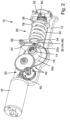
- the door drive 10 comprises an electric motor 18 which is coupled to an output shaft 14 via a gear 20, so that a drive torque generated by the electric motor 18 is transmitted to the output shaft 14 in order to pivot a rod (not shown) coupled to the output shaft 14 in such a way that a door leaf coupled to the rod is transferred from a closed position to an open position.
- the gear 20 is designed as a reduction gear, ie the torque provided by the electric motor 18 is increased by the gear 20, while the speed provided by the electric motor 18 is reduced by the gear 20.
- the gear 20 comprises a worm gear stage 40 and several, here two, spur gear stages 42 with preferably helical spur gears.
- the output shaft 14 is connected in a rotationally fixed manner to a cam disk 16, in the present example a symmetrical cam disk 16.
- An outer circumferential surface 16a (see Fig.2 ) of the cam disk 16 rests on an outer peripheral surface 22a of a roller 22 so that the roller 22 can roll on the outer peripheral surface 16a of the cam disk 16 during operation.
- the roller 22 is rotatably attached to a pivot lever 24.
- the pivot lever 24, which is curved due to the installation space, is in turn attached to a housing 12 of the door drive 10 so that it can pivot about a pivot axis 26.
- a first abutment 34 for an energy storage device 32 in the form of a spiral compression spring is attached to the pivot lever 24, more precisely to a coupling point 38 between the pivot lever 24 and the roller 22.
- the first abutment 34 is mounted on the pivot lever 24 so that it can pivot about an axis 44, which is also the center axis of the roller 22.
- the door drive 10 has a second abutment 36 for the compression spring 32.
- the compression spring 32 is thus arranged between the first abutment 34 and the second abutment 36. While the first abutment 34, guided by the pivot lever 24, can be pivoted about the pivot axis 26, the second abutment 36 is fixedly connected to the housing 12, except for a small compensating movement, which will be explained later, so that the second abutment 36 can support a tension force applied by the first abutment 34 to the compression spring 32 in order to tension the compression spring 32.
- a closing force adjustment device 52 is provided, which in relation to Fig. 7B is described in more detail.
- the motor 18 and the gear 20 are arranged on one side of the output shaft 14 and an energy storage unit 28, which comprises the first abutment 34, the energy storage 32, the second abutment 36 and - if present - the closing force adjustment device 52, is arranged on a side of the output shaft 14 opposite the motor 18 and the gear 20.
- an energy storage unit 28 which comprises the first abutment 34, the energy storage 32, the second abutment 36 and - if present - the closing force adjustment device 52, is arranged on a side of the output shaft 14 opposite the motor 18 and the gear 20.
- FIG. 3A the door drive 10 is shown in its closed position S.
- the roller 22 rests against a concave region 17 of the cam disk 16, which has a relatively short distance to a central axis 64 of the output shaft 14.
- the closing force adjustment device 52 is usually set so that the energy storage device 32 presses on the roller 22 with a relatively small force in the closed position S and thus holds the roller 22 in the concave region 17 of the cam disk 16.
- the cam disk 16 When the electric motor 18 drives the output shaft 14 to open the door leaf, the cam disk 16 is rotated relative to the housing 12 (see arrow in Fig. 3B ). Since the effective distance between the central axis 64 and the circumferential surface 16a of the cam disk 16 increases due to the rotation of the cam disk 16, the roller 22, while it rolls on the circumferential surface 16a, is displaced by the cam disk 16, ie is pressed away from the central axis 64 of the cam disk 16.
- the roller 22 Since the roller 22 is attached to the pivot lever 24 so that it can pivot about the pivot axis 26, the roller 22 moves along a circular path while the roller 22 is displaced by the cam disk 16. Together with the roller 22, the first abutment 34 also moves on the circular path away from the center axis 64 of the output shaft 14 and towards the second abutment 36.
- the energy storage device 32 which is designed as a compression spring, is compressed and thus tensioned. In order to prevent the compression spring 32 from buckling, it has a ratio between the untensioned length of the compression spring and the diameter of the compression spring of less than 2.
- the pivot axis 26 of the pivot lever 24 is arranged offset relative to the position of the coupling point 38 between the pivot lever 24 and the first abutment 34 in the closed position S in the direction of the second abutment 36, i.e. to the right in the figures.
- the pivot axis 26 is arranged as far away as possible from the central axis 30 in the housing 12 in order to obtain as large a pivot radius as possible and thus a small offset in the transverse direction.
- the potential energy stored by the energy storage device 32 can be used to close the door leaf coupled to the door drive 10, for example in the event of a fire.
- the energy storage device 32 presses on the first abutment 36, from which the force is transmitted via the roller 22 directly to the cam disk 16.
- the roller 22 presses on the cam disk 16, causing the cam disk 16 to rotate and thus generating a torque on the output shaft 14 in order to pivot the door leaf.
- the central axis 64 of the output shaft 14 in the closed position S is aligned with the central axis 30 of the energy storage device 32, which results in different torque curves for the door drive 10 depending on the direction of rotation of the output shaft 14, is in the Fig.4
- the central axis 64' of the output shaft 14' in the closed position S is offset from the central axis 30' of the energy storage device 32'.
- the cam disk 16' is aligned so that its axis of symmetry 66' is arranged obliquely to the central axis 30' of the energy storage device 32'. This embodiment has the advantage that almost identical torque curves result in the different directions of rotation.
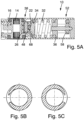
- Fig. 5A is a further sectional view of the door drive 10, wherein the door drive 10 is shown along the central axis 30 of Fig. 3A and perpendicular to the cutting plane according to Fig. 3A It is shown in section.
- Fig. 5A Among other things, it can be seen that a pin 48 is provided for coupling the roller 22 with the first abutment 34 and the pivot lever 26.
- the roller 22 is rotatably mounted on the pin 48 by means of a needle bearing 68.
- the ends of the compression spring 32 are laid and ground and are arranged offset from one another by 180°.
- the total number of turns of the compression spring 32 is not an integer, but ends at approximately X.5 turns, where X is a natural number.
- FIG. 6A and 6B Two different embodiments are shown for the coupling point 38 between the swing lever 24, the roller 22, and the first abutment 34.
- the two embodiments have in common that the pivot lever 24 has a fork-shaped extension 46, in the space between which the roller 22 is arranged.
- the pin 48 for mounting the roller 22 extends parallel to the pivot axis 26 of the pivot lever 24 from one section of the fork-shaped extension 46 to the other section of the fork-shaped extension 46.
- the two different embodiments differ, among other things, in how a receptacle 50 of the first abutment 34 is designed. While in the embodiment according to Fig. 6A the receptacle 50 is formed by a fork-shaped section with two separate holding plates, the receptacle 50 in the embodiment according to Fig. 6B formed by a holder 50 which surrounds the roller 22 on four sides.
- Fig. 7A shows a detailed view of the coupling point 38 and the first abutment 34 from Fig. 5A .
- the pin 48 is rotatably mounted on the pivot lever 26 via a roller bearing 69, for example a needle bearing.
- a plain bearing can be provided.
- the first abutment 34 has, in addition to the receptacle 50 for coupling the abutment 34 with the pin 48, a front-side force-absorbing surface 70 and a radial fixing section 72.
- the radial fixing section 72 engages in the compression spring 32 at the front in order to support the compression spring 32 radially.
- Fig. 7B shows a detailed view of the second abutment 36 and the closing force adjustment device 52 connected to the second abutment 36.
- the second abutment 36 has - mirror image of the first abutment 34 - a frontal force absorption surface 74 and a radial fixing section 76.
- the second abutment 36 has two mutually opposite extensions 78 (cf. Fig.2 ), which engage in corresponding recesses in the housing 12 in such a way that the second abutment 36 is arranged in the housing 12 in a manner secured against rotation.
- the second abutment 36 also has a threaded opening 80, the internal thread of which meshes with a spindle 54.
- the spindle 54 is in turn connected in a rotationally fixed manner to a worm wheel 58, which can be set in rotation from the outside via a worm 60 (cf. Fig.2 ).
- the second abutment 36 can be moved axially by rotating the spindle 54 so that the compression spring 32 can be tensioned or relaxed. So that the second abutment 36 can perform a compensating movement while the first abutment 34 moves along the circular path, i.e. can adapt to the slightly changing axial alignment of the compression spring 32, the spindle 54 is pivotally mounted on the housing 12, here a housing cover 12a, by means of a ball joint 62.
- the ball joint 62 therefore serves to ensure that the spindle 54 automatically aligns itself in the direction of the compression spring center axis 30. and as a result, the compression spring 32 is always held securely between the two abutments 34, 36 without having to provide an additional bearing for the compression spring 32.
- the ball joint 62 can also serve to compensate for manufacturing tolerances. If no closing force adjustment device is provided, the second abutment 36 can nevertheless be arranged in the housing so that it can pivot over an angular range, for example via a ball joint.
- the first abutment 34 is supported solely by the pivot lever 24 and thus does not require a linear bearing. It is also noticeable that the compression spring 32 is only held in position by the two abutments 34, 36 and is thus installed in the door drive 10 in a sort of "floating" manner. This means that very little friction is generated when the door drive 10 is in operation, which makes the door drive 10 efficient and low-maintenance.
Landscapes
- Closing And Opening Devices For Wings, And Checks For Wings (AREA)
- Power-Operated Mechanisms For Wings (AREA)
Claims (15)
- Dispositif d'entraînement (10) pour une porte ou une fenêtre, comprenant un boîtier (12),un arbre de sortie (14) muni d'un disque à cames (16), monté rotatif au niveau du boîtier (12),un moteur électrique (18) avec une transmission (20) pour entraîner l'arbre de sortie (14) d'une position de fermeture (S) dans une direction d'ouverture afin d'ouvrir la porte ou la fenêtre,un galet de roulement (22) roulant en cours de fonctionnement sur le disque à cames (16) en rotation,un levier pivotant (24) qui est articulé au niveau du boîtier (12) en pivotement autour d'un axe de pivotement (26), le galet de roulement (22) étant disposé en rotation au niveau du levier pivotant (24), etune unité d'accumulation d'énergie (28) pour entraîner l'arbre de sortie (14) d'une position d'ouverture (O) dans une direction de fermeture pour fermer la porte ou la fenêtre, dans lequel l'unité d'accumulation d'énergie (28) présente un accumulateur d'énergie (32) présentant un axe longitudinal (30) et une première butée mobile (34) tournée vers le galet de roulement (22), ainsi qu'une deuxième butée (36) détournée du galet de roulement (22), sur lesquelles l'accumulateur d'énergie (32) prend appui,dans lequel le galet de roulement (22) agit en transmission de force entre le disque à cames (16) et la première butée mobile (34) de l'unité d'accumulation d'énergie (28),dans lequel le disque à cames (16) et l'unité d'accumulateur d'énergie (28) sont disposés sur des côtés mutuellement opposés par rapport au levier pivotant (24), etdans lequel la première butée mobile (34) de l'unité d'accumulation d'énergie (28) est accouplée au levier pivotant (24) en un point d'accouplement (38) en rotation et de manière verrouillée en décalage et est ainsi guidée par le levier pivotant (24) sur une trajectoire circulaire,caractérisé en ce que dans la position de fermeture (S), l'axe central (64) de l'arbre de sortie (14) est disposé en alignement avec l'axe longitudinal (30) de l'accumulateur d'énergie (32), ou en ce que dans la position de fermeture (S), l'axe central (64) de l'arbre de sortie (14) est disposé de manière décalée au maximum du diamètre du galet de roulement (22) ou de l'arbre de sortie (14) par rapport à l'axe longitudinal (30) de l'accumulateur d'énergie (32).
- Dispositif d'entraînement (10) selon la revendication 1, caractérisé en ce que la transmission (20) comprend un engrenage à vis sans fin (40) et un réducteur à engrenage droit (42).
- Dispositif d'entraînement (10) selon la revendication 1 ou 2, caractérisé en ce que le moteur électrique (18) et l'unité d'accumulation d'énergie (32) sont disposés sur des côtés opposés par rapport à l'arbre de sortie (14).
- Dispositif d'entraînement (10) selon l'une quelconque des revendications précédentes, caractérisé en ce que le galet de roulement (22) et la première butée mobile (34) sont montés en rotation autour du même axe (44) au niveau du levier pivotant (24).
- Dispositif d'entraînement (10) selon l'une quelconque des revendications précédentes, caractérisé en ce que le levier pivotant (24) présente un prolongement fourchu (46) dans l'espace libre duquel s'étend une tige (48) au niveau de laquelle la première butée mobile (34) est montée en rotation.
- Dispositif d'entraînement (10) selon l'une quelconque des revendications précédentes, caractérisé en ce que la première butée mobile (34) présente un logement (50), en particulier formé par un prolongement fourchu, pour le galet de roulement (22), et dans lequel le galet de roulement (22) est disposé en rotation dans le logement (50).
- Dispositif d'entraînement (10) selon l'une quelconque des revendications précédentes, caractérisé en ce que dans la position de fermeture (S), vu dans la direction d'une extension longitudinale de l'accumulateur d'énergie (28), l'axe de pivotement (26) du levier pivotant (24) est disposé plus loin de l'arbre de sortie (14) que le point d'accouplement (38) entre le levier pivotant (24) et la première butée mobile (34).
- Dispositif d'entraînement (10) selon l'une quelconque des revendications précédentes, caractérisé en ce que lors d'un mouvement de l'arbre de sortie (14) de la position de fermeture (S) à la position d'ouverture (O) et inversement, une excursion du point d'accouplement (38) entre le levier pivotant (24) et la première butée mobile (34) passe perpendiculairement à l'axe longitudinal (30) de l'accumulateur d'énergie (32) par un point d'inversion.
- Dispositif d'entraînement (10) selon l'une quelconque des revendications précédentes, caractérisé en ce que le levier pivotant (24) est courbe.
- Dispositif d'entraînement (10) selon l'une quelconque des revendications précédentes, caractérisé en ce que l'accumulateur d'énergie (32) est réalisé sous forme de ressort, en particulier de ressort de compression, en particulier de ressort de compression en spirale, en particulier dans lequel un diamètre du ressort (32) est supérieur à 60 % d'un diamètre de boîtier, de préférence supérieur à 80 % du diamètre de boîtier, en particulier dans lequel un rapport entre la longueur non tendue du ressort et le diamètre du ressort est inférieur à 3, en particulier inférieur à 2, en particulier dans lequel un nombre de spires total du ressort est compris entre X,3 à X,7, étant en particulier égal à X,5, où X est un nombre naturel, en particulier dans lequel les extrémités du ressort (32) sont rapprochées et/ou meulées et/ou décalées de 180° l'une par rapport à l'autre, en particulier dans lequel le ressort (32) est maintenu exclusivement au niveau de ses zones d'extrémité par les deux butées (34, 36).
- Dispositif d'entraînement (10) selon la revendication 10, caractérisé en ce que la première butée mobile (34) est réalisée sous forme de coupelle de ressort.
- Dispositif d'entraînement (10) selon l'une quelconque des revendications précédentes, caractérisé en ce qu'un dispositif de réglage de force de fermeture (52) est prévu qui permet de régler une force de précontrainte de l'accumulateur d'énergie (32).
- Dispositif d'entraînement (10) selon la revendication 12, caractérisé en ce que le dispositif de réglage de force de fermeture (52) comprend une broche (54) et une coupelle de ressort pouvant être déplacée le long de la broche (54) par une rotation de la broche (54) et qui forme la deuxième butée (36) pour l'accumulateur d'énergie (32), en particulier dans lequel la broche (54) peut être entraînée soit directement, soit par une roue hélicoïdale (58) qui est tournée par une vis sans fin (60), en particulier dans lequel la broche (54) est montée en pivotement dans le boîtier (12) sur une plage angulaire définie, en particulier au moyen d'une rotule (60).
- Dispositif d'entraînement (10) selon l'une quelconque des revendications précédentes, caractérisé en ce que le disque à cames (16) est disposé au moins en partie dans l'alignement avec l'accumulateur d'énergie (32).
- Dispositif d'entraînement (10) selon l'une quelconque des revendications précédentes, caractérisé en ce que le levier pivotant (24) est monté au niveau du boîtier (12) au moyen d'un roulement à aiguilles ou d'un palier lisse.
Applications Claiming Priority (2)
| Application Number | Priority Date | Filing Date | Title |
|---|---|---|---|
| DE102022200954.1A DE102022200954B4 (de) | 2022-01-28 | 2022-01-28 | Antrieb für eine Tür oder ein Fenster |
| PCT/EP2023/051207 WO2023143999A1 (fr) | 2022-01-28 | 2023-01-19 | Entraînement destiné à une porte ou à une fenêtre |
Publications (2)
| Publication Number | Publication Date |
|---|---|
| EP4314459A1 EP4314459A1 (fr) | 2024-02-07 |
| EP4314459B1 true EP4314459B1 (fr) | 2024-08-28 |
Family
ID=85036242
Family Applications (1)
| Application Number | Title | Priority Date | Filing Date |
|---|---|---|---|
| EP23701387.5A Active EP4314459B1 (fr) | 2022-01-28 | 2023-01-19 | Entraînement destiné à une porte ou à une fenêtre |
Country Status (4)
| Country | Link |
|---|---|
| EP (1) | EP4314459B1 (fr) |
| DE (1) | DE102022200954B4 (fr) |
| FI (1) | FI4314459T3 (fr) |
| WO (1) | WO2023143999A1 (fr) |
Families Citing this family (2)
| Publication number | Priority date | Publication date | Assignee | Title |
|---|---|---|---|---|
| DE102023208573B3 (de) | 2023-09-06 | 2024-12-19 | Geze Gmbh | Automatischer Antrieb für eine Drehtür und Drehtür |
| DE102024107399B3 (de) * | 2024-03-15 | 2025-08-21 | Geze Gmbh | Antrieb für eine Tür oder ein Fenster mit verbessertem Wirkungsgrad |
Family Cites Families (5)
| Publication number | Priority date | Publication date | Assignee | Title |
|---|---|---|---|---|
| US2752627A (en) * | 1953-02-26 | 1956-07-03 | George W Houlsby Jr | Pivotal door check device |
| DE10336075B4 (de) * | 2003-08-06 | 2007-06-14 | Agtatec Ag | Antrieb für einen Flügel, insbesondere Drehantrieb für eine Tür, ein Fenster oder dergleichen |
| DE102007002650B4 (de) * | 2007-01-12 | 2020-06-04 | Dormakaba Deutschland Gmbh | Drehflügelantrieb |
| DE102011018738A1 (de) * | 2011-01-14 | 2012-07-19 | Dorma Gmbh + Co. Kg | Drehflügeltürbetätigeraufsatz |
| CH706425A1 (de) | 2012-04-23 | 2013-10-31 | Gilgen Door Systems Ag | Drehantrieb für mindestens einen Flügel, insbesondere eine Türe oder ein Fenster. |
-
2022
- 2022-01-28 DE DE102022200954.1A patent/DE102022200954B4/de active Active
-
2023
- 2023-01-19 EP EP23701387.5A patent/EP4314459B1/fr active Active
- 2023-01-19 FI FIEP23701387.5T patent/FI4314459T3/fi active
- 2023-01-19 WO PCT/EP2023/051207 patent/WO2023143999A1/fr not_active Ceased
Also Published As
| Publication number | Publication date |
|---|---|
| DE102022200954A1 (de) | 2023-08-03 |
| WO2023143999A1 (fr) | 2023-08-03 |
| DE102022200954B4 (de) | 2023-08-31 |
| EP4314459A1 (fr) | 2024-02-07 |
| FI4314459T3 (fi) | 2024-09-23 |
Similar Documents
| Publication | Publication Date | Title |
|---|---|---|
| EP2933415B1 (fr) | Entraînement de porte | |
| EP2841667B1 (fr) | Entrainement pour porte pivotante | |
| EP0207251B2 (fr) | Ferme-porte | |
| EP2693079B1 (fr) | Train épicycloïdal et appareil de manipulation équipé d'un tel train épicycloïdal | |
| EP1298274B1 (fr) | Mécanisme d'entraínement de portes à battants avec dipositif de fermeture à ressort | |
| EP0243786B1 (fr) | Ferme-porte | |
| EP2047050A1 (fr) | Entraînement de porte avec précontrainte de ressort modifiable pendant le mouvement de la porte | |
| EP3634834A1 (fr) | Palier libre, mécanisme de direction et système de direction | |
| DE102022200954B4 (de) | Antrieb für eine Tür oder ein Fenster | |
| WO2023227157A1 (fr) | Agencements de direction pour un véhicule et véhicule ayant une colonne de direction et un agencement de direction | |
| EP2933414A1 (fr) | Entraînement de porte | |
| EP1398442A1 (fr) | Actionneur pour un élément mobile | |
| DE102017130073B3 (de) | Niveauverstellvorrichtung für ein Kraftfahrzeug | |
| WO2012095094A1 (fr) | Garniture d'actionneur de porte battante | |
| DE102011018739A1 (de) | Drehflügeltürbetätigeraufsatz | |
| DE102024107399B3 (de) | Antrieb für eine Tür oder ein Fenster mit verbessertem Wirkungsgrad | |
| DE102023102906B4 (de) | Aktorikeinheit aufweisend Getriebeeinrichtung mit selbstregulierender Übersetzung | |
| DE102015202832B3 (de) | Türantrieb | |
| DE102015202852B3 (de) | Türantrieb | |
| DE102010001742B3 (de) | Verdrehantrieb für eine Tragarmspindel eines Rollenwechslers | |
| EP2640623A1 (fr) | Guide de crémaillère monté sur galets | |
| DE102008054049B4 (de) | Getriebe | |
| DE102005062999A1 (de) | Elektromotorischer Möbelantrieb | |
| EP0841452A2 (fr) | Ferme-porte avec un dispositif de stockage d'énergie pour fermer le battant de porte | |
| DE20200657U1 (de) | Scharniertürhalter für Kraftfahrzeuge |
Legal Events
| Date | Code | Title | Description |
|---|---|---|---|
| STAA | Information on the status of an ep patent application or granted ep patent |
Free format text: STATUS: UNKNOWN |
|
| STAA | Information on the status of an ep patent application or granted ep patent |
Free format text: STATUS: THE INTERNATIONAL PUBLICATION HAS BEEN MADE |
|
| PUAI | Public reference made under article 153(3) epc to a published international application that has entered the european phase |
Free format text: ORIGINAL CODE: 0009012 |
|
| STAA | Information on the status of an ep patent application or granted ep patent |
Free format text: STATUS: REQUEST FOR EXAMINATION WAS MADE |
|
| 17P | Request for examination filed |
Effective date: 20231030 |
|
| AK | Designated contracting states |
Kind code of ref document: A1 Designated state(s): AL AT BE BG CH CY CZ DE DK EE ES FI FR GB GR HR HU IE IS IT LI LT LU LV MC ME MK MT NL NO PL PT RO RS SE SI SK SM TR |
|
| GRAP | Despatch of communication of intention to grant a patent |
Free format text: ORIGINAL CODE: EPIDOSNIGR1 |
|
| STAA | Information on the status of an ep patent application or granted ep patent |
Free format text: STATUS: GRANT OF PATENT IS INTENDED |
|
| DAV | Request for validation of the european patent (deleted) | ||
| DAX | Request for extension of the european patent (deleted) | ||
| INTG | Intention to grant announced |
Effective date: 20240423 |
|
| GRAS | Grant fee paid |
Free format text: ORIGINAL CODE: EPIDOSNIGR3 |
|
| GRAA | (expected) grant |
Free format text: ORIGINAL CODE: 0009210 |
|
| STAA | Information on the status of an ep patent application or granted ep patent |
Free format text: STATUS: THE PATENT HAS BEEN GRANTED |
|
| AK | Designated contracting states |
Kind code of ref document: B1 Designated state(s): AL AT BE BG CH CY CZ DE DK EE ES FI FR GB GR HR HU IE IS IT LI LT LU LV MC ME MK MT NL NO PL PT RO RS SE SI SK SM TR |
|
| REG | Reference to a national code |
Ref country code: CH Ref legal event code: EP |
|
| REG | Reference to a national code |
Ref country code: DE Ref legal event code: R096 Ref document number: 502023000130 Country of ref document: DE |
|
| REG | Reference to a national code |
Ref country code: FI Ref legal event code: FGE |
|
| REG | Reference to a national code |
Ref country code: IE Ref legal event code: FG4D Free format text: LANGUAGE OF EP DOCUMENT: GERMAN |
|
| REG | Reference to a national code |
Ref country code: SE Ref legal event code: TRGR |
|
| P01 | Opt-out of the competence of the unified patent court (upc) registered |
Free format text: CASE NUMBER: APP_54444/2024 Effective date: 20241002 |
|
| REG | Reference to a national code |
Ref country code: LT Ref legal event code: MG9D |
|
| PG25 | Lapsed in a contracting state [announced via postgrant information from national office to epo] |
Ref country code: GR Free format text: LAPSE BECAUSE OF FAILURE TO SUBMIT A TRANSLATION OF THE DESCRIPTION OR TO PAY THE FEE WITHIN THE PRESCRIBED TIME-LIMIT Effective date: 20241129 Ref country code: NL Free format text: LAPSE BECAUSE OF FAILURE TO SUBMIT A TRANSLATION OF THE DESCRIPTION OR TO PAY THE FEE WITHIN THE PRESCRIBED TIME-LIMIT Effective date: 20240828 Ref country code: PT Free format text: LAPSE BECAUSE OF FAILURE TO SUBMIT A TRANSLATION OF THE DESCRIPTION OR TO PAY THE FEE WITHIN THE PRESCRIBED TIME-LIMIT Effective date: 20241230 Ref country code: PL Free format text: LAPSE BECAUSE OF FAILURE TO SUBMIT A TRANSLATION OF THE DESCRIPTION OR TO PAY THE FEE WITHIN THE PRESCRIBED TIME-LIMIT Effective date: 20240828 |
|
| PG25 | Lapsed in a contracting state [announced via postgrant information from national office to epo] |
Ref country code: BG Free format text: LAPSE BECAUSE OF FAILURE TO SUBMIT A TRANSLATION OF THE DESCRIPTION OR TO PAY THE FEE WITHIN THE PRESCRIBED TIME-LIMIT Effective date: 20240828 |
|
| PG25 | Lapsed in a contracting state [announced via postgrant information from national office to epo] |
Ref country code: LV Free format text: LAPSE BECAUSE OF FAILURE TO SUBMIT A TRANSLATION OF THE DESCRIPTION OR TO PAY THE FEE WITHIN THE PRESCRIBED TIME-LIMIT Effective date: 20240828 |
|
| REG | Reference to a national code |
Ref country code: NL Ref legal event code: MP Effective date: 20240828 |
|
| PG25 | Lapsed in a contracting state [announced via postgrant information from national office to epo] |
Ref country code: IS Free format text: LAPSE BECAUSE OF FAILURE TO SUBMIT A TRANSLATION OF THE DESCRIPTION OR TO PAY THE FEE WITHIN THE PRESCRIBED TIME-LIMIT Effective date: 20241228 |
|
| PG25 | Lapsed in a contracting state [announced via postgrant information from national office to epo] |
Ref country code: HR Free format text: LAPSE BECAUSE OF FAILURE TO SUBMIT A TRANSLATION OF THE DESCRIPTION OR TO PAY THE FEE WITHIN THE PRESCRIBED TIME-LIMIT Effective date: 20240828 |
|
| PG25 | Lapsed in a contracting state [announced via postgrant information from national office to epo] |
Ref country code: ES Free format text: LAPSE BECAUSE OF FAILURE TO SUBMIT A TRANSLATION OF THE DESCRIPTION OR TO PAY THE FEE WITHIN THE PRESCRIBED TIME-LIMIT Effective date: 20240828 Ref country code: RS Free format text: LAPSE BECAUSE OF FAILURE TO SUBMIT A TRANSLATION OF THE DESCRIPTION OR TO PAY THE FEE WITHIN THE PRESCRIBED TIME-LIMIT Effective date: 20241128 |
|
| PG25 | Lapsed in a contracting state [announced via postgrant information from national office to epo] |
Ref country code: RS Free format text: LAPSE BECAUSE OF FAILURE TO SUBMIT A TRANSLATION OF THE DESCRIPTION OR TO PAY THE FEE WITHIN THE PRESCRIBED TIME-LIMIT Effective date: 20241128 Ref country code: PT Free format text: LAPSE BECAUSE OF FAILURE TO SUBMIT A TRANSLATION OF THE DESCRIPTION OR TO PAY THE FEE WITHIN THE PRESCRIBED TIME-LIMIT Effective date: 20241230 Ref country code: PL Free format text: LAPSE BECAUSE OF FAILURE TO SUBMIT A TRANSLATION OF THE DESCRIPTION OR TO PAY THE FEE WITHIN THE PRESCRIBED TIME-LIMIT Effective date: 20240828 Ref country code: NL Free format text: LAPSE BECAUSE OF FAILURE TO SUBMIT A TRANSLATION OF THE DESCRIPTION OR TO PAY THE FEE WITHIN THE PRESCRIBED TIME-LIMIT Effective date: 20240828 Ref country code: LV Free format text: LAPSE BECAUSE OF FAILURE TO SUBMIT A TRANSLATION OF THE DESCRIPTION OR TO PAY THE FEE WITHIN THE PRESCRIBED TIME-LIMIT Effective date: 20240828 Ref country code: IS Free format text: LAPSE BECAUSE OF FAILURE TO SUBMIT A TRANSLATION OF THE DESCRIPTION OR TO PAY THE FEE WITHIN THE PRESCRIBED TIME-LIMIT Effective date: 20241228 Ref country code: HR Free format text: LAPSE BECAUSE OF FAILURE TO SUBMIT A TRANSLATION OF THE DESCRIPTION OR TO PAY THE FEE WITHIN THE PRESCRIBED TIME-LIMIT Effective date: 20240828 Ref country code: GR Free format text: LAPSE BECAUSE OF FAILURE TO SUBMIT A TRANSLATION OF THE DESCRIPTION OR TO PAY THE FEE WITHIN THE PRESCRIBED TIME-LIMIT Effective date: 20241129 Ref country code: ES Free format text: LAPSE BECAUSE OF FAILURE TO SUBMIT A TRANSLATION OF THE DESCRIPTION OR TO PAY THE FEE WITHIN THE PRESCRIBED TIME-LIMIT Effective date: 20240828 Ref country code: BG Free format text: LAPSE BECAUSE OF FAILURE TO SUBMIT A TRANSLATION OF THE DESCRIPTION OR TO PAY THE FEE WITHIN THE PRESCRIBED TIME-LIMIT Effective date: 20240828 |
|
| PG25 | Lapsed in a contracting state [announced via postgrant information from national office to epo] |
Ref country code: SM Free format text: LAPSE BECAUSE OF FAILURE TO SUBMIT A TRANSLATION OF THE DESCRIPTION OR TO PAY THE FEE WITHIN THE PRESCRIBED TIME-LIMIT Effective date: 20240828 Ref country code: DK Free format text: LAPSE BECAUSE OF FAILURE TO SUBMIT A TRANSLATION OF THE DESCRIPTION OR TO PAY THE FEE WITHIN THE PRESCRIBED TIME-LIMIT Effective date: 20240828 Ref country code: RO Free format text: LAPSE BECAUSE OF FAILURE TO SUBMIT A TRANSLATION OF THE DESCRIPTION OR TO PAY THE FEE WITHIN THE PRESCRIBED TIME-LIMIT Effective date: 20240828 |
|
| PG25 | Lapsed in a contracting state [announced via postgrant information from national office to epo] |
Ref country code: EE Free format text: LAPSE BECAUSE OF FAILURE TO SUBMIT A TRANSLATION OF THE DESCRIPTION OR TO PAY THE FEE WITHIN THE PRESCRIBED TIME-LIMIT Effective date: 20240828 |
|
| PG25 | Lapsed in a contracting state [announced via postgrant information from national office to epo] |
Ref country code: CZ Free format text: LAPSE BECAUSE OF FAILURE TO SUBMIT A TRANSLATION OF THE DESCRIPTION OR TO PAY THE FEE WITHIN THE PRESCRIBED TIME-LIMIT Effective date: 20240828 |
|
| PG25 | Lapsed in a contracting state [announced via postgrant information from national office to epo] |
Ref country code: SK Free format text: LAPSE BECAUSE OF FAILURE TO SUBMIT A TRANSLATION OF THE DESCRIPTION OR TO PAY THE FEE WITHIN THE PRESCRIBED TIME-LIMIT Effective date: 20240828 Ref country code: IT Free format text: LAPSE BECAUSE OF FAILURE TO SUBMIT A TRANSLATION OF THE DESCRIPTION OR TO PAY THE FEE WITHIN THE PRESCRIBED TIME-LIMIT Effective date: 20240828 |
|
| REG | Reference to a national code |
Ref country code: DE Ref legal event code: R097 Ref document number: 502023000130 Country of ref document: DE |
|
| PLBE | No opposition filed within time limit |
Free format text: ORIGINAL CODE: 0009261 |
|
| STAA | Information on the status of an ep patent application or granted ep patent |
Free format text: STATUS: NO OPPOSITION FILED WITHIN TIME LIMIT |
|
| 26N | No opposition filed |
Effective date: 20250530 |
|
| PG25 | Lapsed in a contracting state [announced via postgrant information from national office to epo] |
Ref country code: MC Free format text: LAPSE BECAUSE OF FAILURE TO SUBMIT A TRANSLATION OF THE DESCRIPTION OR TO PAY THE FEE WITHIN THE PRESCRIBED TIME-LIMIT Effective date: 20240828 Ref country code: LU Free format text: LAPSE BECAUSE OF NON-PAYMENT OF DUE FEES Effective date: 20250119 |
|
| PG25 | Lapsed in a contracting state [announced via postgrant information from national office to epo] |
Ref country code: BE Free format text: LAPSE BECAUSE OF NON-PAYMENT OF DUE FEES Effective date: 20250131 |
|
| PG25 | Lapsed in a contracting state [announced via postgrant information from national office to epo] |
Ref country code: FR Free format text: LAPSE BECAUSE OF NON-PAYMENT OF DUE FEES Effective date: 20250131 |
|
| REG | Reference to a national code |
Ref country code: BE Ref legal event code: MM Effective date: 20250131 |
|
| PG25 | Lapsed in a contracting state [announced via postgrant information from national office to epo] |
Ref country code: IE Free format text: LAPSE BECAUSE OF NON-PAYMENT OF DUE FEES Effective date: 20250119 |
|
| PGFP | Annual fee paid to national office [announced via postgrant information from national office to epo] |
Ref country code: SE Payment date: 20260121 Year of fee payment: 4 |
|
| PGFP | Annual fee paid to national office [announced via postgrant information from national office to epo] |
Ref country code: NO Payment date: 20260123 Year of fee payment: 4 Ref country code: DE Payment date: 20260131 Year of fee payment: 4 |
|
| PGFP | Annual fee paid to national office [announced via postgrant information from national office to epo] |
Ref country code: AT Payment date: 20260301 Year of fee payment: 4 |
|
| PGFP | Annual fee paid to national office [announced via postgrant information from national office to epo] |
Ref country code: FI Payment date: 20260129 Year of fee payment: 4 |
|
| PG25 | Lapsed in a contracting state [announced via postgrant information from national office to epo] |
Ref country code: CY Free format text: LAPSE BECAUSE OF FAILURE TO SUBMIT A TRANSLATION OF THE DESCRIPTION OR TO PAY THE FEE WITHIN THE PRESCRIBED TIME-LIMIT Effective date: 20240828 |
|
| PG25 | Lapsed in a contracting state [announced via postgrant information from national office to epo] |
Ref country code: TR Free format text: LAPSE BECAUSE OF FAILURE TO SUBMIT A TRANSLATION OF THE DESCRIPTION OR TO PAY THE FEE WITHIN THE PRESCRIBED TIME-LIMIT Effective date: 20240828 |
|
| PG25 | Lapsed in a contracting state [announced via postgrant information from national office to epo] |
Ref country code: LT Free format text: LAPSE BECAUSE OF FAILURE TO SUBMIT A TRANSLATION OF THE DESCRIPTION OR TO PAY THE FEE WITHIN THE PRESCRIBED TIME-LIMIT Effective date: 20240828 |