EP2933507B1 - Stossverbindungsanordnung, fenster-/türrahmen oder fenster-/türflügelrahmen sowie rahmenprofilelement - Google Patents
Stossverbindungsanordnung, fenster-/türrahmen oder fenster-/türflügelrahmen sowie rahmenprofilelement Download PDFInfo
- Publication number
- EP2933507B1 EP2933507B1 EP15163854.1A EP15163854A EP2933507B1 EP 2933507 B1 EP2933507 B1 EP 2933507B1 EP 15163854 A EP15163854 A EP 15163854A EP 2933507 B1 EP2933507 B1 EP 2933507B1
- Authority
- EP
- European Patent Office
- Prior art keywords
- butt joint
- frame
- window
- plug connecting
- joint arrangement
- Prior art date
- Legal status (The legal status is an assumption and is not a legal conclusion. Google has not performed a legal analysis and makes no representation as to the accuracy of the status listed.)
- Active
Links
- 210000001503 joint Anatomy 0.000 title claims description 57
- 238000003780 insertion Methods 0.000 claims description 53
- 230000037431 insertion Effects 0.000 claims description 53
- 238000005304 joining Methods 0.000 claims description 49
- 239000002023 wood Substances 0.000 claims description 10
- 239000007787 solid Substances 0.000 claims description 4
- 235000008331 Pinus X rigitaeda Nutrition 0.000 claims 1
- 235000011613 Pinus brutia Nutrition 0.000 claims 1
- 241000018646 Pinus brutia Species 0.000 claims 1
- 239000003292 glue Substances 0.000 description 21
- 239000011324 bead Substances 0.000 description 10
- 238000004519 manufacturing process Methods 0.000 description 7
- 239000003973 paint Substances 0.000 description 7
- 238000012549 training Methods 0.000 description 7
- 238000013461 design Methods 0.000 description 5
- 239000000463 material Substances 0.000 description 5
- 241000191291 Abies alba Species 0.000 description 4
- 238000000576 coating method Methods 0.000 description 4
- 238000011161 development Methods 0.000 description 4
- 230000018109 developmental process Effects 0.000 description 4
- 238000009434 installation Methods 0.000 description 4
- 239000004922 lacquer Substances 0.000 description 4
- 230000008961 swelling Effects 0.000 description 4
- 238000004026 adhesive bonding Methods 0.000 description 3
- 230000013011 mating Effects 0.000 description 3
- 208000027418 Wounds and injury Diseases 0.000 description 2
- 230000006378 damage Effects 0.000 description 2
- 230000012447 hatching Effects 0.000 description 2
- 208000014674 injury Diseases 0.000 description 2
- 238000010422 painting Methods 0.000 description 2
- 238000004321 preservation Methods 0.000 description 2
- 238000007792 addition Methods 0.000 description 1
- 238000004873 anchoring Methods 0.000 description 1
- 239000011248 coating agent Substances 0.000 description 1
- 150000001875 compounds Chemical class 0.000 description 1
- 230000001419 dependent effect Effects 0.000 description 1
- 230000001066 destructive effect Effects 0.000 description 1
- 238000001035 drying Methods 0.000 description 1
- 230000007613 environmental effect Effects 0.000 description 1
- 230000002093 peripheral effect Effects 0.000 description 1
- 239000002994 raw material Substances 0.000 description 1
- 238000000926 separation method Methods 0.000 description 1
Images


Classifications
-
- E—FIXED CONSTRUCTIONS
- E06—DOORS, WINDOWS, SHUTTERS, OR ROLLER BLINDS IN GENERAL; LADDERS
- E06B—FIXED OR MOVABLE CLOSURES FOR OPENINGS IN BUILDINGS, VEHICLES, FENCES OR LIKE ENCLOSURES IN GENERAL, e.g. DOORS, WINDOWS, BLINDS, GATES
- E06B3/00—Window sashes, door leaves, or like elements for closing wall or like openings; Layout of fixed or moving closures, e.g. windows in wall or like openings; Features of rigidly-mounted outer frames relating to the mounting of wing frames
- E06B3/96—Corner joints or edge joints for windows, doors, or the like frames or wings
- E06B3/984—Corner joints or edge joints for windows, doors, or the like frames or wings specially adapted for frame members of wood or other material worked in a similar way
-
- F—MECHANICAL ENGINEERING; LIGHTING; HEATING; WEAPONS; BLASTING
- F16—ENGINEERING ELEMENTS AND UNITS; GENERAL MEASURES FOR PRODUCING AND MAINTAINING EFFECTIVE FUNCTIONING OF MACHINES OR INSTALLATIONS; THERMAL INSULATION IN GENERAL
- F16B—DEVICES FOR FASTENING OR SECURING CONSTRUCTIONAL ELEMENTS OR MACHINE PARTS TOGETHER, e.g. NAILS, BOLTS, CIRCLIPS, CLAMPS, CLIPS OR WEDGES; JOINTS OR JOINTING
- F16B12/00—Jointing of furniture or the like, e.g. hidden from exterior
- F16B12/10—Jointing of furniture or the like, e.g. hidden from exterior using pegs, bolts, tenons, clamps, clips, or the like
- F16B12/12—Jointing of furniture or the like, e.g. hidden from exterior using pegs, bolts, tenons, clamps, clips, or the like for non-metal furniture parts, e.g. made of wood, of plastics
- F16B12/26—Jointing of furniture or the like, e.g. hidden from exterior using pegs, bolts, tenons, clamps, clips, or the like for non-metal furniture parts, e.g. made of wood, of plastics using snap-action elements
-
- F—MECHANICAL ENGINEERING; LIGHTING; HEATING; WEAPONS; BLASTING
- F16—ENGINEERING ELEMENTS AND UNITS; GENERAL MEASURES FOR PRODUCING AND MAINTAINING EFFECTIVE FUNCTIONING OF MACHINES OR INSTALLATIONS; THERMAL INSULATION IN GENERAL
- F16B—DEVICES FOR FASTENING OR SECURING CONSTRUCTIONAL ELEMENTS OR MACHINE PARTS TOGETHER, e.g. NAILS, BOLTS, CIRCLIPS, CLAMPS, CLIPS OR WEDGES; JOINTS OR JOINTING
- F16B12/00—Jointing of furniture or the like, e.g. hidden from exterior
- F16B12/44—Leg joints; Corner joints
- F16B12/46—Non-metal corner connections
-
- E—FIXED CONSTRUCTIONS
- E06—DOORS, WINDOWS, SHUTTERS, OR ROLLER BLINDS IN GENERAL; LADDERS
- E06B—FIXED OR MOVABLE CLOSURES FOR OPENINGS IN BUILDINGS, VEHICLES, FENCES OR LIKE ENCLOSURES IN GENERAL, e.g. DOORS, WINDOWS, BLINDS, GATES
- E06B3/00—Window sashes, door leaves, or like elements for closing wall or like openings; Layout of fixed or moving closures, e.g. windows in wall or like openings; Features of rigidly-mounted outer frames relating to the mounting of wing frames
- E06B3/96—Corner joints or edge joints for windows, doors, or the like frames or wings
- E06B3/964—Corner joints or edge joints for windows, doors, or the like frames or wings using separate connection pieces, e.g. T-connection pieces
- E06B3/9642—Butt type joints with at least one frame member cut off square; T-shape joints
-
- F—MECHANICAL ENGINEERING; LIGHTING; HEATING; WEAPONS; BLASTING
- F16—ENGINEERING ELEMENTS AND UNITS; GENERAL MEASURES FOR PRODUCING AND MAINTAINING EFFECTIVE FUNCTIONING OF MACHINES OR INSTALLATIONS; THERMAL INSULATION IN GENERAL
- F16B—DEVICES FOR FASTENING OR SECURING CONSTRUCTIONAL ELEMENTS OR MACHINE PARTS TOGETHER, e.g. NAILS, BOLTS, CIRCLIPS, CLAMPS, CLIPS OR WEDGES; JOINTS OR JOINTING
- F16B5/00—Joining sheets or plates, e.g. panels, to one another or to strips or bars parallel to them
- F16B5/0004—Joining sheets, plates or panels in abutting relationship
- F16B5/0008—Joining sheets, plates or panels in abutting relationship by moving the sheets, plates or panels substantially in their own plane, perpendicular to the abutting edge
- F16B5/0012—Joining sheets, plates or panels in abutting relationship by moving the sheets, plates or panels substantially in their own plane, perpendicular to the abutting edge a tongue on the edge of one sheet, plate or panel co-operating with a groove in the edge of another sheet, plate or panel
- F16B5/0016—Joining sheets, plates or panels in abutting relationship by moving the sheets, plates or panels substantially in their own plane, perpendicular to the abutting edge a tongue on the edge of one sheet, plate or panel co-operating with a groove in the edge of another sheet, plate or panel with snap action
Definitions
- the present invention relates to a butt joint arrangement as well as a window / door frame or window / door frame with such a butt joint arrangement and a frame profile element for such a window / door frame or window / door frame.
- window frames or door frames or sash frames or door sash frames exist in various embodiments.
- these are sometimes mostly so-called spigot connections, in which an extension or a separate connecting piece is pressed into recesses of the frame parts and glued or otherwise secured therein.
- a pin connection is for example in the DD 210 324 A1 described.
- the spigot connection accordingly has a circular-cylindrical connecting pin which is introduced into holes provided on the connecting surfaces of the elementary parts of the frame to be joined.
- the connecting pin is clamped by means of clamping bolts, which are inserted in transverse bores through the elementary parts of the frame and the connecting pin, in the bore.
- pre-painted items are used for assembly. These are individually easier to paint than the entire frame and also each have for themselves a complete paint seal, especially at the joint areas on.
- pre-painted parts there is the problem that the existing paint layer is violated in the joint area.
- the injury comes about, for example, by the force application for joining the parts and / or by friction of the pins on the recesses or on walls of the holes during insertion.
- the pins are usually pressed into the recesses.
- the corresponding fits through the paint are also subject to inaccuracies. Ultimately, therefore, occur during joining strong friction, so that the paint layer often broken up locally and / or sheared off or otherwise injured.
- the present invention seeks to provide an improved joint connection arrangement for window / door frames or window / door frame, in particular of wooden windows.
- this object is achieved by a butt joint arrangement with the features of claim 1 and / or by a window / door frame or window / door frame with the features of claim 12 and / or by a frame profile element with the features of claim 13.
- the knowledge / idea on which the present invention is based is to minimize the necessary application of force and frictional forces when producing a butt joint by providing a plug-in connection element or a plug-in recess with a configuration tapering in the insertion direction.
- no forces are required to insert the connector element in the EinsteckausNeillung until shortly before reaching the final position.
- Frictional forces only arise when the final frictional connection is established, when the plug connection element is already almost in its final position.
- a violation of the lacquer layer of pre-painted frame profile elements during the joining of the same can thus be at least largely or completely avoided.
- a positive and / or non-positive connection can be created without the need for undercuts on the joining sections. Due to the undercut-free design of the joining sections, these can advantageous simply be plugged into each other head-on, in particular without that they have to slide off each other. Advantageously, such a simple installation, in particular without the need for a press, allows.
- the present invention thus enables the production of more durable window or casement frames, as well as the lacquer layer on and in the joint sections, especially in pre-painted parts, remains intact, which advantageously means optimal wood protection.
- the plug-in connection element can be integrated in the first joining section and tapered from the joining section.
- the plug connection element can also be provided as a separate part.
- an additional insertion recess may be provided on the first joint section.
- the separate plug connection element can then have a center with maximum thickness and taper from there into both plug-in directions of the first and second joint sections.
- the plug connection element and the insertion recess can be hidden in the joint or within the joint connection arrangement or not visible from the outside.
- an attractive appearance of the butt joint is thus created.
- the plug connection element is provided as a plug connection pin provided on the first joining section educated.
- the plug connection pin is formed integrally with the first frame profile element.
- the frame profile elements can be inserted into each other for joining in particular without additional connecting elements.
- the plug-in pin is preferably in front of the joint section and tapers forward in the insertion direction.
- the plug connection element and the Einsteckaus Principleung are formed oblong transversely to the direction of insertion. Due to the elongated design, the contact surface is increased, and thus advantageously created a more stable connector. Furthermore, by the elongated training in addition also provides a rotation. As an alternative to an elongated design, a plurality of individual plug connection elements and insertion recesses could also be provided in a row.
- the second joint section has a further insertion recess.
- the joining sections are then formed by means of two plug-in connection elements form-fitting together. In this way, a particularly intimate bond between the frame profile elements is provided. Furthermore, the dimensional accuracy of the connection is increased by the provision of additional contact surfaces.
- the joining sections are preferably joined together by simultaneously inserting the plug connection elements into the insertion recesses of the second joining section.
- the first joint section could also have a insertion recess. Then, the joining would be accomplished by simultaneously inserting the Plug connection elements in the Einsteckauslangruc of the first and second joining section.
- the insertion recesses have a common insertion direction.
- the insertion recesses are aligned at an angle to each other.
- the Einsteckaus traditions traditions are perpendicular to each other.
- the common plug-in direction ensures that the frame profile elements can be joined with a single joining operation or a single relative movement.
- the angle thereby causes the plug connection elements can slide on differently oriented side walls of the Einsteckaus traditions.
- the plug connection elements automatically slide into the predetermined position within the insertion recesses so that the frame profile elements are positioned relative to one another.
- the EinsteckauslangauerInstitut are aligned perpendicular to each other, this positioning is carried out both in the transverse and in the longitudinal direction.
- the plug connection element tapers steadily in the plugging direction.
- the training may also be truncated, in particular conical or cone truncated, that is formed with a capped end.
- different base surfaces of the conical or conical or conical or Konusstumpfierin training are conceivable.
- the base is provided round or as a rectangle with rounded edges.
- an elongated connector element has the cone or konfumpfieri training a correspondingly elongated base.
- a wide variety of inlet angles of continuous tapering come into question.
- inlet angles as small as 0.01 ° come into question.
- a stable anchoring of the connector element in the Einsteckaus Principleung can be realized at angles of up to 45 °.
- in practice can be easily implemented inlet angles in the range of 0.5 to 30 °.
- Preferred inlet angles are in the range between 1 and 20 °.
- the Einsteckaus brieflyung is designed as a connector element corresponding to tapering in the insertion direction pocket.
- This has a bottom and circumferential side walls.
- a so-called glue pocket can thus be provided at the bottom of the bag, if gluing of the joining sections is intended.
- a passage opening in the second frame profile element which tapers correspondingly to the plug connection element in the insertion direction would also be conceivable.
- the direct contact surface between the connector element and EinsteckausNeill supraung is increased.
- an enlarged support surface for receiving power can be provided.
- this can provide an increased frictional or force fit between the plug connection element and the insertion recess.
- the necessary amount of glue can also be reduced because fewer voids are present between the joining sections, which are usually filled with glue.
- the insertion recess has a depth that is greater than the insertable length of the connector element is provided. To this way, on the one hand a double fit is prevented and, on the other hand, advantageously a glue pocket is provided which provides a compensation volume for excess glue. Advantageously, leakage or swelling of the glue from the butt joints is thus reduced or prevented.
- the frame profile elements are designed as painted solid wood parts.
- Particularly preferred are completely varnished solid wood parts, which are prepainted in particular in the region of the joint sections.
- varnished solid wood parts have a high level of environmental compatibility, especially since the material is a renewable raw material.
- they also have optimum weather resistance due to the complete coating.
- the assembly is simplified by the use of pre-painted parts, because after the joining no painting steps are necessary.
- weatherproof or durable butt joint arrangements can be created, which are particularly easy and efficient to assemble.
- the plug connection element has circumferentially circumferential grooves.
- the Einsteckauslangung may have circumferentially circumferential grooves. This is particularly advantageous when the butt joint assembly is to be made glued.
- the circumferential grooves then form so-called glue locks, which form a compensation volume for excess glue in the joint area and thus prevent swelling of the glue from the joints of the joint.
- the plug connection element and the EinsteckausEnglishung on each other corresponding locking means can thus advantageously the Frame profile elements are fixed together without glue.
- the locking means may also be advantageous in glued versions, because the locking means provide a certain biasing force or holding force.
- this also makes any on-site installation at the installation site possible or easier.
- the latching means are formed as circumferentially encircling bead and corresponding circumferentially circumferential groove.
- a snap connection is created. It can be provided either the bead on the connector element and the groove in the side wall of the Einsteckaus brieflyung, or vice versa. If the butt joint arrangement is not glued, then the locking connection between the bead and the groove can also be reversibly reopened and closed, if a force overcoming the detent force is applied against the mating direction.
- a Christmas tree gearing can also be provided as latching means.
- a fir tree toothing is provided tapering on the plug connection element in the insertion direction and has a plurality of latching teeth, which are formed in particular at a certain height circumferentially around the plug connection element.
- the ratchet teeth can form barbs, which can be guided into the insertion and in forming a frictional connection locally in the side wall or in engage specially provided grooves of EinsteckausEnglishung.
- counter teeth or corresponding counter-locking grooves can be provided in the side wall of the insertion.
- the first joint section has a protruding plug connection pin, which tapers in the insertion direction.
- a plurality of frame profile elements can be plugged together to form a window / door frame or window / door frame.
- the plug-in direction may correspond to the plug-in direction of the EinsteckausEnglishung on the second joint section, but not necessarily.
- the plugging direction of the EinsteckausANSANS is oriented perpendicular to the longitudinal direction of the frame profile element for forming a corner joint of a rectangular frame
- the plugging direction of the plug-in pin corresponds to the longitudinal direction of the frame profile element.
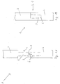
- FIGS. 1A and 1B show a butt joint arrangement according to a first embodiment.
- the representation is to be understood as a schematic sectional representation through the butt joint arrangement, with hatching being dispensed with for clarity.
- the butt joint arrangement 1 has a first frame profile element 2 and a second frame profile element 4.
- the first frame profile element 2 has a first joining section 3, on which a plug connection pin 7 is provided.
- the second frame profile element 4 has a second joint section 5, on which a Einsteckaus supraung 6 is provided.
- the plug-in pin 7 has a tapering in the insertion direction 8 training.
- the plug connection pin 7 is provided here as a truncated cone formed integrally with the first frame profile element 2.
- a plug connection element is conceivable, for example, as a likewise insertable into the first frame profile element item with two frustoconical ends.
- other tapered shapes such as a cone shape with a curved outer surface, conceivable.
- the insertion recess 6 is formed as a pocket with a bottom and circumferential side walls with a shape corresponding to the shape of the plug-in pin shape.
- FIG. 1A shows an exploded state of the frame profile elements 2, 4 before joining or mating in the insertion direction.
- FIG. 1B shows a mated or positively and / or non-positively assembled state of the frame profile elements 2, 4th
- FIGS. 2A and 2B show a schematic representation of a butt joint assembly 1 according to another embodiment. Analogous to the representation in FIGS. 1A and 1B it is a schematic sectional view, with hatching was omitted for clarity.
- the butt joint arrangement 1 here has two plug connection pins 7 and 7 'on the first joint section.
- the first joining section has a step 17, the first plug connection pin 7 being provided on a front step end face of the joining section 3 in the insertion direction 8 and the second plug connection pin 7 'being provided on a second stepped end face set back by the step 17.
- the plug connection pins 7, 7 ' are each formed transversely to the insertion direction 8 oblong. They are also arranged perpendicular to each other, with respect to FIG. 3 will be discussed in more detail. In the illustrated sectional plane of the first plug-in pin 7 is thus in the longitudinal profile, while the second plug-in pin 7 is shown in the transverse profile.
- the second joint section 5 is formed corresponding to the first joint section 3. That is, here a first Einsteckausnaturalung 6 and a second Einsteckausnaturalung 7 is present, wherein the Einsteckausnaturalept 6, 6 'are provided in each case at a front and a recessed stepped end face of the second joint section 5.
- the Einsteckausnaturalept 6, 6 'of the second joining portion are each formed as pockets and have a bottom 15 and peripheral side walls 16.
- the bottom 15 is provided at a depth 9 of the Einsteckausnaturalung 6, which is greater than the insertable length 10 of the corresponding plug-in pin 7 is formed.
- a glue pocket is provided at the bottom thereof. This acts as a compensation volume for excess glue to prevent the glue from swelling out of the joints when joining. Furthermore, the greater depth also serves to avoid a stop of the plug-in pin on the bottom 15 of the bag in order to prevent a double fit.
- an inlet angle 15 of approximately two to four degrees is drawn on the second insertion recess 6 ', which is transferable to the first insertion opening 6 and the plug connection pins 7, 7'.
- FIG. 3 shows in perspective view a window / door frame or window / door frame with a butt joint arrangement according to FIG. 2B ,
- the illustration is merely a section of such a frame, the section showing an example of a corner joint.
- Hidden lines show hidden contours. This serves in particular to illustrate the design and positioning of the first and second plug connection pins 7, 7 'or the first and second plug-in recesses 6, 6'.
- the first insertion recess 6 has a longitudinal extension direction, which is aligned transversely to the longitudinal direction 19 of the second frame profile element 4.
- the second insertion recess 6 ' is formed in its longitudinal extension direction parallel to the longitudinal direction 19 of the second frame profile element 4.
- the Einsteckaus traditions 6, 6 ' are thus perpendicular to each other.
- the level 17 can either serve for inserting a window glazing in a window / door frame or as a stop window or door frame.
- a rectangular frame a total of four of the illustrated vertical corner joints are provided with corresponding butt joints 1, which are formed with a total of four frame profile elements.
- Each of the frame profile elements 2, 4 accordingly has a corresponding first joint section 3 with plug connection pins 7, 7 'and a second joint section 5 with insertion recesses 6, 6'.
- the plug-in direction of the Einsteckaus traditions 6, 6 ' is perpendicular to the longitudinal direction 18 and 19 of the respective frame profile element 2 and 4, wherein the plug-in direction 8 of the plug connection pin 7, 7' of the longitudinal direction 18 and 19 of the frame profile element 2 and 4 corresponds.
- FIGS. 4A, 4B to 6A, 6B provide alternatives to the in FIGS. 2A and 2B They are similar to the second embodiment as well as a window / door frame or window / door frame 20 according to FIG. 3 transferable.
- FIGS. 4A and 4B show a schematic representation of a butt joint assembly according to a third embodiment.
- the plug connection pin 7, 7 'circumferential grooves 11 are provided. These serve as so-called glue locks which, when joining the butt joint arrangement, provide a compensation volume for excess glue present in the joining sections. As a result, swelling of the glue from the joining sections during joining is prevented.
- FIGS. 5A and 5B show a schematic representation of a butt joint assembly according to a fourth embodiment.
- the joining sections here with Locking means are formed, which in the form of provided on the plug connection pin 7, 7 'circumferential beads 12 and on the inner walls of the Einsteckaus traditions 6, 6' provided corresponding circumferential grooves 13 are formed.
- the plug connection pins 7, 7 ' are inserted into the insertion recesses 6, 6'.
- Shortly before reaching the final position of the plug connection pin 7, 7 'in the Einsteckaus Principleungen 6, 6' are the beads 12 in an area which is just before the corresponding grooves 13, on the side walls 16 of the Einsteckausnaturalept 6, 6 '.
- a locking force in the insertion direction 8 must be applied, which elastically deforms the beads 12 and the regions of the side walls 16 in the grooves 13, so that the beads 12 in the grooves 13th slide in and a locked state according to FIG. 5B is reached. In this locked state, the beads 12 and grooves 13 are then, as in FIG. 5b shown, locked together.
- this latching connection is again reversibly separable by the latching force is overcome by a corresponding tensile force in the opposite direction of insertion.
- FIGS. 6A, 6B schematically show a butt joint arrangement according to a fifth embodiment.
- the locking means are designed here as Tannenbaumvertechnikung 14.
- the Christmas tree toothing 14 is provided on the tapered plug connection pins 7, 7 'and formed with circumferential toothings.
- the revolving gears are also arranged in a tapered manner on the plug-in connection pin 7, 7 '.
- the butt joint arrangement can in principle be combined with an additional gluing, so that an additional material bond is created.
- the butt joint arrangement need not necessarily be a corner joint. In question, but rather T-joints or butt joints. Furthermore, butt joints in other angular positions are conceivable, which are in the range between 0 and 90 °, for example at a 45 ° angle. In addition, it may also be a corner joint, in which the joining sections are aligned at a 45 ° angle to the longitudinal direction of the frame profile elements.
- the plug-in direction can either be aligned 45 ° to the longitudinal direction of the frame profile element either. Alternatively, the plugging direction can also be oriented at a 45 ° angle to the joining section, that is to say then again in the longitudinal direction of the frame profile element or perpendicularly thereto.
Landscapes
- Engineering & Computer Science (AREA)
- General Engineering & Computer Science (AREA)
- Mechanical Engineering (AREA)
- Civil Engineering (AREA)
- Structural Engineering (AREA)
- Joining Of Corner Units Of Frames Or Wings (AREA)
Priority Applications (1)
| Application Number | Priority Date | Filing Date | Title |
|---|---|---|---|
| PL15163854T PL2933507T3 (pl) | 2014-04-16 | 2015-04-16 | Zespół złącza na styk, ościeżnica okienna / drzwiowa lub rama skrzydła okiennego / drzwiowego oraz element profilu drzwiowego |
Applications Claiming Priority (1)
| Application Number | Priority Date | Filing Date | Title |
|---|---|---|---|
| DE102014207322.7A DE102014207322A1 (de) | 2014-04-16 | 2014-04-16 | Stoßverbindungsanordnung, Fenster-/Türrahmen oder Fenster-/Türflügelrahmen sowie Rahmenprofilelement |
Publications (2)
| Publication Number | Publication Date |
|---|---|
| EP2933507A1 EP2933507A1 (de) | 2015-10-21 |
| EP2933507B1 true EP2933507B1 (de) | 2019-06-12 |
Family
ID=53002512
Family Applications (1)
| Application Number | Title | Priority Date | Filing Date |
|---|---|---|---|
| EP15163854.1A Active EP2933507B1 (de) | 2014-04-16 | 2015-04-16 | Stossverbindungsanordnung, fenster-/türrahmen oder fenster-/türflügelrahmen sowie rahmenprofilelement |
Country Status (4)
| Country | Link |
|---|---|
| EP (1) | EP2933507B1 (da) |
| DE (1) | DE102014207322A1 (da) |
| DK (1) | DK2933507T3 (da) |
| PL (1) | PL2933507T3 (da) |
Families Citing this family (4)
| Publication number | Priority date | Publication date | Assignee | Title |
|---|---|---|---|---|
| JP2017210789A (ja) * | 2016-05-25 | 2017-11-30 | 大建工業株式会社 | 建具枠 |
| DE102017211420A1 (de) * | 2017-07-05 | 2019-01-10 | Bayerische Motoren Werke Aktiengesellschaft | Fahrzeugbauteil und Verfahren zur Herstellung desselben |
| CA3095346A1 (en) | 2018-03-29 | 2019-10-03 | Masonite Corporation | Panel doors and related method |
| CN109578405B (zh) * | 2018-12-24 | 2023-09-08 | 美克国际家私(天津)制造有限公司 | 一种三边实木框等边榫拼装结构 |
Family Cites Families (9)
| Publication number | Priority date | Publication date | Assignee | Title |
|---|---|---|---|---|
| CH545904A (da) * | 1972-04-27 | 1974-02-15 | ||
| HU181385B (en) | 1981-09-28 | 1983-07-28 | Faipari Kutato Intezet | Frame from rodlike details particularly sash frame |
| GB2240744A (en) * | 1990-02-12 | 1991-08-14 | Raymond Charles Jeffer Cooksey | Scribe & counter scribe joint |
| JP2565272B2 (ja) * | 1992-04-09 | 1996-12-18 | 秀雄 宮澤 | ドア枠内隅等のコーナー内隅の連結方法 |
| DE102006040901B4 (de) | 2006-08-31 | 2008-06-26 | Leitz Gmbh & Co. Kg | Fensterelement und Werkzeug zur Bearbeitung der Fensterkanteln |
| IT1397160B1 (it) * | 2009-01-27 | 2013-01-04 | Radaelli Angelo S A S Di Renata Vagni Radaelli & C | Struttura di semilavorato per la realizzazione di serramenti e suo metodo di fabbricazione |
| DE202011001627U1 (de) * | 2011-01-17 | 2012-04-18 | Hans Hundegger | Schwalbenschwanzverbindung |
| DE102012012213A1 (de) * | 2012-03-20 | 2013-09-26 | Leitz Gmbh & Co. Kg | Einrichtung zum Verbinden zweier Kanteln |
| DE102012009035B9 (de) * | 2012-03-20 | 2016-03-03 | Leitz Gmbh & Co. Kg | Einrichtung zum Verbinden zweier Kanteln |
-
2014
- 2014-04-16 DE DE102014207322.7A patent/DE102014207322A1/de not_active Withdrawn
-
2015
- 2015-04-16 EP EP15163854.1A patent/EP2933507B1/de active Active
- 2015-04-16 PL PL15163854T patent/PL2933507T3/pl unknown
- 2015-04-16 DK DK15163854.1T patent/DK2933507T3/da active
Non-Patent Citations (1)
| Title |
|---|
| None * |
Also Published As
| Publication number | Publication date |
|---|---|
| PL2933507T3 (pl) | 2019-12-31 |
| DK2933507T3 (da) | 2019-09-16 |
| DE102014207322A1 (de) | 2015-10-22 |
| EP2933507A1 (de) | 2015-10-21 |
Similar Documents
| Publication | Publication Date | Title |
|---|---|---|
| EP2901888B1 (de) | Möbel | |
| DE102011057018B4 (de) | Leimloser Korpus | |
| DE102013100352A1 (de) | Leimloser Plattenverbund sowie Verfahren zum leimlosen Verbinden zweier Plattenelemente | |
| EP2933507B1 (de) | Stossverbindungsanordnung, fenster-/türrahmen oder fenster-/türflügelrahmen sowie rahmenprofilelement | |
| DE102017117093A1 (de) | Batteriekasten | |
| EP2597398A2 (de) | Modulrahmen für ein Fotovoltaik- oder Solarmodul | |
| EP3135849A1 (de) | Stossverbinder für kleber-injekzion sowie stassverbinder - kombinazion und rahmen | |
| DE102008061709A1 (de) | Dichtungsprofil, Verbindungsvorrichtung und Dichtung | |
| DE102012009035B4 (de) | Einrichtung zum Verbinden zweier Kanteln | |
| DE102011120374A1 (de) | Eckverbinderprofil mit schlitzförmiger Nut | |
| EP3557084B1 (de) | Verbindungselement zum verbinden von profilelementen | |
| DE10237802B4 (de) | Verbindungsbeschlag für Pfosten-Riegel-Holzkonstruktionen,insbesondere vor Ort endzumontierende Ganzfassaden-Holzkonstruktionen | |
| AT519258B1 (de) | Verbinder für Hohlprofile | |
| DE2300281A1 (de) | Verstaerkungs-winkel fuer eckverbindungen von fenstern, tueren und aehnlichen bauteilen aus kunststoffprofilen zur erhoehung der stabilitaet und gestaltfestigkeit | |
| DE1914446A1 (de) | Ausfuehrung einer Kraefte uebertragenden Steckverbindung der Enden profilierter Metallrohre zur Bildung eines gestellartigen Gebrauchsmoebels | |
| AT510908B1 (de) | Blendrahmen | |
| EP3916188B1 (de) | Verbindungsvorrichtung zur verbindung von zwei bauelementen im stossbereich des türen- oder fensterbaues, sowie verfahren zur herstellung einer solchen gehrungsverbindung an zwei bauelementen | |
| AT519395B1 (de) | Schachtmodul | |
| EP3354837A1 (de) | Verfahren zur herstellung einer isolierglasscheibe und isolierglasscheibe | |
| DE4041161C2 (de) | Verbindungsvorrichtung für eine Sprossenkonstruktion und Verfahren zur Herstellung einer Sprossenkonstruktion mit dieser Verbindungsvorrichtung | |
| DE202004004696U1 (de) | Verbindungszapfen | |
| DE202019103487U1 (de) | Spreizbarer Eckwinkel | |
| DE202009010271U1 (de) | Verbindung von aus Pappe, Karton oder Hartpapier bestehenden Hohlprofilen miteinander | |
| AT412412B (de) | Adapterprofil | |
| DE202015101420U1 (de) | Eckmontagesatz |
Legal Events
| Date | Code | Title | Description |
|---|---|---|---|
| PUAI | Public reference made under article 153(3) epc to a published international application that has entered the european phase |
Free format text: ORIGINAL CODE: 0009012 |
|
| AK | Designated contracting states |
Kind code of ref document: A1 Designated state(s): AL AT BE BG CH CY CZ DE DK EE ES FI FR GB GR HR HU IE IS IT LI LT LU LV MC MK MT NL NO PL PT RO RS SE SI SK SM TR |
|
| AX | Request for extension of the european patent |
Extension state: BA ME |
|
| 17P | Request for examination filed |
Effective date: 20160421 |
|
| RBV | Designated contracting states (corrected) |
Designated state(s): AL AT BE BG CH CY CZ DE DK EE ES FI FR GB GR HR HU IE IS IT LI LT LU LV MC MK MT NL NO PL PT RO RS SE SI SK SM TR |
|
| GRAP | Despatch of communication of intention to grant a patent |
Free format text: ORIGINAL CODE: EPIDOSNIGR1 |
|
| STAA | Information on the status of an ep patent application or granted ep patent |
Free format text: STATUS: GRANT OF PATENT IS INTENDED |
|
| INTG | Intention to grant announced |
Effective date: 20190102 |
|
| GRAS | Grant fee paid |
Free format text: ORIGINAL CODE: EPIDOSNIGR3 |
|
| GRAA | (expected) grant |
Free format text: ORIGINAL CODE: 0009210 |
|
| STAA | Information on the status of an ep patent application or granted ep patent |
Free format text: STATUS: THE PATENT HAS BEEN GRANTED |
|
| AK | Designated contracting states |
Kind code of ref document: B1 Designated state(s): AL AT BE BG CH CY CZ DE DK EE ES FI FR GB GR HR HU IE IS IT LI LT LU LV MC MK MT NL NO PL PT RO RS SE SI SK SM TR |
|
| REG | Reference to a national code |
Ref country code: GB Ref legal event code: FG4D Free format text: NOT ENGLISH |
|
| REG | Reference to a national code |
Ref country code: CH Ref legal event code: EP |
|
| REG | Reference to a national code |
Ref country code: AT Ref legal event code: REF Ref document number: 1142929 Country of ref document: AT Kind code of ref document: T Effective date: 20190615 |
|
| REG | Reference to a national code |
Ref country code: IE Ref legal event code: FG4D Free format text: LANGUAGE OF EP DOCUMENT: GERMAN |
|
| REG | Reference to a national code |
Ref country code: DE Ref legal event code: R096 Ref document number: 502015009279 Country of ref document: DE |
|
| REG | Reference to a national code |
Ref country code: CH Ref legal event code: NV Representative=s name: NOVAGRAAF INTERNATIONAL SA, CH |
|
| REG | Reference to a national code |
Ref country code: DK Ref legal event code: T3 Effective date: 20190912 |
|
| REG | Reference to a national code |
Ref country code: NL Ref legal event code: MP Effective date: 20190612 |
|
| REG | Reference to a national code |
Ref country code: LT Ref legal event code: MG4D |
|
| REG | Reference to a national code |
Ref country code: NO Ref legal event code: T2 Effective date: 20190612 |
|
| PG25 | Lapsed in a contracting state [announced via postgrant information from national office to epo] |
Ref country code: HR Free format text: LAPSE BECAUSE OF FAILURE TO SUBMIT A TRANSLATION OF THE DESCRIPTION OR TO PAY THE FEE WITHIN THE PRESCRIBED TIME-LIMIT Effective date: 20190612 Ref country code: LT Free format text: LAPSE BECAUSE OF FAILURE TO SUBMIT A TRANSLATION OF THE DESCRIPTION OR TO PAY THE FEE WITHIN THE PRESCRIBED TIME-LIMIT Effective date: 20190612 Ref country code: FI Free format text: LAPSE BECAUSE OF FAILURE TO SUBMIT A TRANSLATION OF THE DESCRIPTION OR TO PAY THE FEE WITHIN THE PRESCRIBED TIME-LIMIT Effective date: 20190612 Ref country code: SE Free format text: LAPSE BECAUSE OF FAILURE TO SUBMIT A TRANSLATION OF THE DESCRIPTION OR TO PAY THE FEE WITHIN THE PRESCRIBED TIME-LIMIT Effective date: 20190612 Ref country code: AL Free format text: LAPSE BECAUSE OF FAILURE TO SUBMIT A TRANSLATION OF THE DESCRIPTION OR TO PAY THE FEE WITHIN THE PRESCRIBED TIME-LIMIT Effective date: 20190612 |
|
| PG25 | Lapsed in a contracting state [announced via postgrant information from national office to epo] |
Ref country code: RS Free format text: LAPSE BECAUSE OF FAILURE TO SUBMIT A TRANSLATION OF THE DESCRIPTION OR TO PAY THE FEE WITHIN THE PRESCRIBED TIME-LIMIT Effective date: 20190612 Ref country code: LV Free format text: LAPSE BECAUSE OF FAILURE TO SUBMIT A TRANSLATION OF THE DESCRIPTION OR TO PAY THE FEE WITHIN THE PRESCRIBED TIME-LIMIT Effective date: 20190612 Ref country code: GR Free format text: LAPSE BECAUSE OF FAILURE TO SUBMIT A TRANSLATION OF THE DESCRIPTION OR TO PAY THE FEE WITHIN THE PRESCRIBED TIME-LIMIT Effective date: 20190913 Ref country code: BG Free format text: LAPSE BECAUSE OF FAILURE TO SUBMIT A TRANSLATION OF THE DESCRIPTION OR TO PAY THE FEE WITHIN THE PRESCRIBED TIME-LIMIT Effective date: 20190912 |
|
| PG25 | Lapsed in a contracting state [announced via postgrant information from national office to epo] |
Ref country code: NL Free format text: LAPSE BECAUSE OF FAILURE TO SUBMIT A TRANSLATION OF THE DESCRIPTION OR TO PAY THE FEE WITHIN THE PRESCRIBED TIME-LIMIT Effective date: 20190612 Ref country code: PT Free format text: LAPSE BECAUSE OF FAILURE TO SUBMIT A TRANSLATION OF THE DESCRIPTION OR TO PAY THE FEE WITHIN THE PRESCRIBED TIME-LIMIT Effective date: 20191014 Ref country code: SK Free format text: LAPSE BECAUSE OF FAILURE TO SUBMIT A TRANSLATION OF THE DESCRIPTION OR TO PAY THE FEE WITHIN THE PRESCRIBED TIME-LIMIT Effective date: 20190612 Ref country code: CZ Free format text: LAPSE BECAUSE OF FAILURE TO SUBMIT A TRANSLATION OF THE DESCRIPTION OR TO PAY THE FEE WITHIN THE PRESCRIBED TIME-LIMIT Effective date: 20190612 Ref country code: RO Free format text: LAPSE BECAUSE OF FAILURE TO SUBMIT A TRANSLATION OF THE DESCRIPTION OR TO PAY THE FEE WITHIN THE PRESCRIBED TIME-LIMIT Effective date: 20190612 Ref country code: EE Free format text: LAPSE BECAUSE OF FAILURE TO SUBMIT A TRANSLATION OF THE DESCRIPTION OR TO PAY THE FEE WITHIN THE PRESCRIBED TIME-LIMIT Effective date: 20190612 |
|
| PG25 | Lapsed in a contracting state [announced via postgrant information from national office to epo] |
Ref country code: IS Free format text: LAPSE BECAUSE OF FAILURE TO SUBMIT A TRANSLATION OF THE DESCRIPTION OR TO PAY THE FEE WITHIN THE PRESCRIBED TIME-LIMIT Effective date: 20191012 Ref country code: ES Free format text: LAPSE BECAUSE OF FAILURE TO SUBMIT A TRANSLATION OF THE DESCRIPTION OR TO PAY THE FEE WITHIN THE PRESCRIBED TIME-LIMIT Effective date: 20190612 Ref country code: SM Free format text: LAPSE BECAUSE OF FAILURE TO SUBMIT A TRANSLATION OF THE DESCRIPTION OR TO PAY THE FEE WITHIN THE PRESCRIBED TIME-LIMIT Effective date: 20190612 Ref country code: IT Free format text: LAPSE BECAUSE OF FAILURE TO SUBMIT A TRANSLATION OF THE DESCRIPTION OR TO PAY THE FEE WITHIN THE PRESCRIBED TIME-LIMIT Effective date: 20190612 |
|
| REG | Reference to a national code |
Ref country code: DE Ref legal event code: R097 Ref document number: 502015009279 Country of ref document: DE |
|
| PG25 | Lapsed in a contracting state [announced via postgrant information from national office to epo] |
Ref country code: TR Free format text: LAPSE BECAUSE OF FAILURE TO SUBMIT A TRANSLATION OF THE DESCRIPTION OR TO PAY THE FEE WITHIN THE PRESCRIBED TIME-LIMIT Effective date: 20190612 |
|
| PLBE | No opposition filed within time limit |
Free format text: ORIGINAL CODE: 0009261 |
|
| STAA | Information on the status of an ep patent application or granted ep patent |
Free format text: STATUS: NO OPPOSITION FILED WITHIN TIME LIMIT |
|
| 26N | No opposition filed |
Effective date: 20200313 |
|
| PG25 | Lapsed in a contracting state [announced via postgrant information from national office to epo] |
Ref country code: IS Free format text: LAPSE BECAUSE OF FAILURE TO SUBMIT A TRANSLATION OF THE DESCRIPTION OR TO PAY THE FEE WITHIN THE PRESCRIBED TIME-LIMIT Effective date: 20200224 Ref country code: SI Free format text: LAPSE BECAUSE OF FAILURE TO SUBMIT A TRANSLATION OF THE DESCRIPTION OR TO PAY THE FEE WITHIN THE PRESCRIBED TIME-LIMIT Effective date: 20190612 |
|
| PG2D | Information on lapse in contracting state deleted |
Ref country code: IS |
|
| PGFP | Annual fee paid to national office [announced via postgrant information from national office to epo] |
Ref country code: DE Payment date: 20200430 Year of fee payment: 6 |
|
| REG | Reference to a national code |
Ref country code: DK Ref legal event code: EBP Effective date: 20200430 Ref country code: NO Ref legal event code: MMEP |
|
| PG25 | Lapsed in a contracting state [announced via postgrant information from national office to epo] |
Ref country code: MC Free format text: LAPSE BECAUSE OF FAILURE TO SUBMIT A TRANSLATION OF THE DESCRIPTION OR TO PAY THE FEE WITHIN THE PRESCRIBED TIME-LIMIT Effective date: 20190612 |
|
| REG | Reference to a national code |
Ref country code: CH Ref legal event code: PL |
|
| PG25 | Lapsed in a contracting state [announced via postgrant information from national office to epo] |
Ref country code: FR Free format text: LAPSE BECAUSE OF NON-PAYMENT OF DUE FEES Effective date: 20200430 Ref country code: LI Free format text: LAPSE BECAUSE OF NON-PAYMENT OF DUE FEES Effective date: 20200430 Ref country code: CH Free format text: LAPSE BECAUSE OF NON-PAYMENT OF DUE FEES Effective date: 20200430 Ref country code: LU Free format text: LAPSE BECAUSE OF NON-PAYMENT OF DUE FEES Effective date: 20200416 Ref country code: NO Free format text: LAPSE BECAUSE OF NON-PAYMENT OF DUE FEES Effective date: 20200430 |
|
| REG | Reference to a national code |
Ref country code: BE Ref legal event code: MM Effective date: 20200430 |
|
| PG25 | Lapsed in a contracting state [announced via postgrant information from national office to epo] |
Ref country code: BE Free format text: LAPSE BECAUSE OF NON-PAYMENT OF DUE FEES Effective date: 20200430 |
|
| GBPC | Gb: european patent ceased through non-payment of renewal fee |
Effective date: 20200416 |
|
| PG25 | Lapsed in a contracting state [announced via postgrant information from national office to epo] |
Ref country code: IE Free format text: LAPSE BECAUSE OF NON-PAYMENT OF DUE FEES Effective date: 20200416 Ref country code: GB Free format text: LAPSE BECAUSE OF NON-PAYMENT OF DUE FEES Effective date: 20200416 Ref country code: DK Free format text: LAPSE BECAUSE OF NON-PAYMENT OF DUE FEES Effective date: 20200430 |
|
| REG | Reference to a national code |
Ref country code: AT Ref legal event code: MM01 Ref document number: 1142929 Country of ref document: AT Kind code of ref document: T Effective date: 20200416 |
|
| PG25 | Lapsed in a contracting state [announced via postgrant information from national office to epo] |
Ref country code: AT Free format text: LAPSE BECAUSE OF NON-PAYMENT OF DUE FEES Effective date: 20200416 |
|
| REG | Reference to a national code |
Ref country code: DE Ref legal event code: R119 Ref document number: 502015009279 Country of ref document: DE |
|
| PG25 | Lapsed in a contracting state [announced via postgrant information from national office to epo] |
Ref country code: DE Free format text: LAPSE BECAUSE OF NON-PAYMENT OF DUE FEES Effective date: 20211103 |
|
| PG25 | Lapsed in a contracting state [announced via postgrant information from national office to epo] |
Ref country code: MT Free format text: LAPSE BECAUSE OF FAILURE TO SUBMIT A TRANSLATION OF THE DESCRIPTION OR TO PAY THE FEE WITHIN THE PRESCRIBED TIME-LIMIT Effective date: 20190612 Ref country code: CY Free format text: LAPSE BECAUSE OF FAILURE TO SUBMIT A TRANSLATION OF THE DESCRIPTION OR TO PAY THE FEE WITHIN THE PRESCRIBED TIME-LIMIT Effective date: 20190612 |
|
| PG25 | Lapsed in a contracting state [announced via postgrant information from national office to epo] |
Ref country code: MK Free format text: LAPSE BECAUSE OF FAILURE TO SUBMIT A TRANSLATION OF THE DESCRIPTION OR TO PAY THE FEE WITHIN THE PRESCRIBED TIME-LIMIT Effective date: 20190612 |
|
| PG25 | Lapsed in a contracting state [announced via postgrant information from national office to epo] |
Ref country code: PL Free format text: LAPSE BECAUSE OF NON-PAYMENT OF DUE FEES Effective date: 20200416 |