EP2933532A2 - Exzentrisches reduzierstück - Google Patents
Exzentrisches reduzierstück Download PDFInfo
- Publication number
- EP2933532A2 EP2933532A2 EP15163340.1A EP15163340A EP2933532A2 EP 2933532 A2 EP2933532 A2 EP 2933532A2 EP 15163340 A EP15163340 A EP 15163340A EP 2933532 A2 EP2933532 A2 EP 2933532A2
- Authority
- EP
- European Patent Office
- Prior art keywords
- pin
- carrier
- hole
- holes
- carrier member
- Prior art date
- Legal status (The legal status is an assumption and is not a legal conclusion. Google has not performed a legal analysis and makes no representation as to the accuracy of the status listed.)
- Granted
Links
Images


Classifications
-
- F—MECHANICAL ENGINEERING; LIGHTING; HEATING; WEAPONS; BLASTING
- F16—ENGINEERING ELEMENTS AND UNITS; GENERAL MEASURES FOR PRODUCING AND MAINTAINING EFFECTIVE FUNCTIONING OF MACHINES OR INSTALLATIONS; THERMAL INSULATION IN GENERAL
- F16H—GEARING
- F16H1/00—Toothed gearings for conveying rotary motion
- F16H1/28—Toothed gearings for conveying rotary motion with gears having orbital motion
- F16H1/32—Toothed gearings for conveying rotary motion with gears having orbital motion in which the central axis of the gearing lies inside the periphery of an orbital gear
-
- F—MECHANICAL ENGINEERING; LIGHTING; HEATING; WEAPONS; BLASTING
- F16—ENGINEERING ELEMENTS AND UNITS; GENERAL MEASURES FOR PRODUCING AND MAINTAINING EFFECTIVE FUNCTIONING OF MACHINES OR INSTALLATIONS; THERMAL INSULATION IN GENERAL
- F16H—GEARING
- F16H1/00—Toothed gearings for conveying rotary motion
- F16H1/28—Toothed gearings for conveying rotary motion with gears having orbital motion
- F16H1/32—Toothed gearings for conveying rotary motion with gears having orbital motion in which the central axis of the gearing lies inside the periphery of an orbital gear
- F16H2001/323—Toothed gearings for conveying rotary motion with gears having orbital motion in which the central axis of the gearing lies inside the periphery of an orbital gear comprising eccentric crankshafts driving or driven by a gearing
Definitions
- the present invention relates to an eccentric reducer having a carrier composed at least two members fastened to each other.
- a reducer which is configured to output a large torque from a power source, such as an electric motor, is known in the prior art, as disclosed e.g. in patent document 1.
- a driving motor as a power source rotates in such a reducer
- a crank shaft rotates via an input shaft, a driven external gear, etc.
- the load of an eccentric portion secured to the crank shaft acts on a pinion (external-tooth gear), whereby the external-tooth gear rotates eccentrically and the crank shaft, rotatably held by the external-tooth gear, revolves while rotating.
- the revolving movement of the crank shaft rotates a carrier that rotatably holds the crank shaft.
- a large torque can thus be obtained from a transmission gear secured to the carrier.
- the carrier of the reducer disclosed in patent document 1 comprises a base portion (first carrier member) and an end plate portion (second carrier member) which are fixed to each other by pin members and bolts (fastening section).
- Each pin member is pressed into pin holes, formed in both the base carrier and the end carrier, such that it straddles the two pin holes.
- Each bolt is threaded into screw holes, formed in the base carrier and in the end carrier, such that it straddles the two holes. In this manner, the two carriers are firmly fixed to each other.
- Patent document 1 Japanese Patent Laid-Open Publication No. 2006-283983
- the present invention has been made to solve the above problem, and it is an object of the present invention to provide an eccentric reducer which can securely prevent pin members, which have been pressed into pin holes to fix a first carrier member and a second carrier member to each other, from escaping from the pin holes.
- the first carrier member and the second carrier member can be firmly fixed to each other by means of the pin member and the fastening section.
- This can provide the carrier composed of the first carrier member and the second carrier member firmly fixed to each other.
- at least part of the opening of the through-hole, into which the pin member has been inserted, is covered by a portion of the fastening member. If, for some reason, the pin member is moved in a direction exiting the through-hole, the pin member is stopped by the portion of the fastening section.
- the portion of the fastening section functions as a cover portion which prevents the pin member, which has been pressed into the through-hole, from escaping from the through-hole.
- the eccentric reducer of the present invention can therefore securely prevent the pin member, which has been pressed into the pin holes to fix the first carrier member and the second carrier member to each other, from escaping (coming off)from the pin holes.
- a part of the fastening section for fixing the two carrier members to each other is provide as a cover portion. This can prevent escape of the pin member from the pin holes without the need for provision of a separate member as a cover to prevent escape of the pin member.
- the eccentric reducer of this embodiment can prevent escape of the pin member from the pin holes by means of the washer provided as a part of the fastening section. Because washers can be produced e.g. by punching with a press, there is a relatively small variation in the size between washers. This enables the washer to more securely cover part of the pin through-hole into which the pin member has been inserted, thereby more securely preventing escape of the pin member from the pin through-hole.
- the eccentric reducer of this embodiment can prevent escape of the pin member from the pin holes by means of the screw head provided as a part of the fastening section. Because of a relatively small variation in the size, a screw head can more securely prevent escape of the pin member from the holes.
- the eccentric reducer of the present invention can securely prevent the pin member(s), which has been pressed into the pin holes to fix the first carrier member and the second carrier member to each other, from escaping from the pin holes.
- An eccentric reducer 1 is suitable for use in, for example, a yaw-drive device for yaw-driving a nacelle to rotate it with respect to a tower of a wind turbine, or a pitch-drive device for pitch-driving the shaft of a blade with respect to a nacelle-side hub.
- the eccentric reducer 1 of this embodiment is usable not only in a wind turbine, but in a variety of industrial machines or construction machines as well.
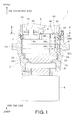
- FIG. 1 is a partial cross-sectional view of the eccentric reducer 1 of this embodiment.
- the eccentric reducer 1 is configured to reduce the speed of rotation inputted from a motor (not shown), and transmit and output the reduced rotation.
- the eccentric reducer 1 includes a case 2, in input gear 4 (driving gear), a reducing section 10, an output shaft 5, etc.
- a pinion 6 is formed integrally with the output shaft 5 which projects from the case 2, and a motor (not shown) is mounted to the case 2 at the upper other end of the eccentric reducer 1.
- the rotation inputted from the motor is reduced by the reducing section 10, and the torque is transmitted and outputted to the pinion 6 of the output shaft 5.
- the lower side or the output side of the eccentric reducer 1 shown in FIG. 1 where the output shaft 5 is disposed, may be referred to as one-end side
- the upper side or the input side of the eccentric reducer 1, where the motor is mounted may be referred to as the other-end side.
- the other-end side may sometimes be referred to as the upper side or upper, while the one-end side may sometimes be referred to as the lower side or lower.
- the case 2 consists of a plurality of case members which are fastened to each other, and has a vertically-extending generally-cylindrical shape.
- the reducing section 10, etc. are housed in the case 2.
- Vertically-extending pin internal teeth (not shown) are arranged on the inner peripheral surface of the case 2 at regular intervals along the circumferential direction of the case 2. The pin internal teeth are configured to engage the below-described external-tooth gears 25.
- the input gear 4 is comprised of a short shaft-shaped gear member and formed integrally with the rotating shaft 3 of the motor.
- the rotating shaft 3 of the motor is provided as an input shaft to which the rotary driving force of the motor is inputted.
- a gear portion that engages the teeth portions of spur gears 11 of the reducing section 10 is formed in the peripheral surface of the input gear 4.
- the input gear 4 is configured to input the rotary driving force from the motor to the spur gears 11.
- the reducing section 10 comprises the spur gears 11, crank shafts 20, external-tooth gears 25 (gear section), a carrier 30, etc.
- the spur gear 11 are provided as driven gears which are driven by the input gear 4.
- a plurality of (four in this embodiment) spur gears 11 that engage the teeth portion of the input gear 4 are disposed around the input gear 4.
- the spur gears 11 are arranged at regular intervals (90-degree intervals in this embodiment) along the circumferential direction of the input gear 4.
- the spur gears 11 are in spline engagement with the crank shafts 20.
- crank shafts 20 are arranged at regular intervals along the circumferential direction of the inner periphery of the case 2.
- Each crank shaft 20 is disposed such that it penetrates through a crank hole (not shown) formed in each of the external-tooth gears 25, and is configured as a shaft member which, when rotated, eccentrically rotates the external-tooth gears 25.
- Each crank shaft 20 makes a revolving movement in conjunction with the rotation of the external-tooth gears 25 caused by the rotation of the crank shaft 20.
- the spur gears 11 are each mounted to an upper portion of each crank shaft 20.
- the external-tooth gears 25 are vertically arranged parallel to each other and housed in the case 2.
- the crank shafts 20 are inserted into the external-tooth gears 25 at regular intervals in the circumferential direction.
- each external-tooth gear 25 constitutes a gear having the external teeth that engage the pin internal teeth.
- the number of the external teeth of each external-tooth gear 25 is smaller by at least one than the number of the pin internal teeth. Accordingly, the position of engagement between the external teeth and the pin internal teeth is displaced every time each crank shaft 20 rotates 360 degrees, whereby the external-tooth gears 25 oscillate and rotate eccentrically.
- the external-tooth gears 25 rotatably hold the crank shafts 20 by means of external-tooth bearings (not shown).
- the carrier 30 rotatably holds the external-tooth gears 25 by means of crank bearings 33, 34, and is rotatably held by carrier bearings 7, 8.
- the carrier 30 comprises an assembly of a base carrier 31 (first carrier member), an end carrier 32 (second carrier member), a plurality of pin members 41, a plurality of fastening sections 40, etc.
- the base carrier 31 includes a disk portion 35 and a plurality of (four in this embodiment) support post portions 36, which are formed integrally.
- the disk portion 35 is a generally disk-shaped portion having a somewhat large vertical thickness.
- the support post portions 36 extend upward from the disk portion 35.
- Each support post portion 36 has one bolt hole 36a and two bottomed pin holes 36b.
- the bolt hole 36a extends downward from the upper surface of the support post portion 36.
- a female screw is formed in the inner peripheral surface of the bolt hole 36a.
- each bottomed pin hole 36b extends downward from the upper surface of the support post portion 36.
- the inner periphery of each bottomed pin hole 36b has a circular shape in a cross-section perpendicular to a direction in which the bottomed pin hole 36b extends.
- the end carrier 32 includes a disk portion 37 and a plurality of (four in this embodiment) support post portions 38, which are formed integrally.
- the disk portion 37 is a generally disk-shaped portion having a somewhat large vertical thickness.
- the support post portions 38 extend downward from the disk portion 37.
- Each support post portion 38 has one bolt hole 38a and two pin through-holes 38b.
- the bolt hole 38a and each pin through-hole 38b of each support post portion 38 overlap with the corresponding bolt hole 36a and bottomed pin hole 36b.
- the bolt hole 38a vertically penetrates through the support post portion 38.
- a female screw is formed in the inner peripheral surface of the bolt hole 38a.
- the diameter of the bolt hole 38a is equal to the diameter of the bolt hole 36a formed in the base carrier 31.
- each pin through-hole 38b vertically penetrates through the support post portion 38.
- the inner periphery of each pin through-hole 38b has a circular shape in a cross-section perpendicular to a direction in which the pin through-hole 38b extends.
- the diameter of each pin through-hole 38b is equal to the diameter of each bottomed pin hole 36b.
- the pin members 41 each have a round rod-like shape.
- the diameter of each pin member 41 is somewhat larger than the diameter of each bottomed pin hole 36b and the diameter of each pin through-hole 38b.
- FIG. 2 is a diagram showing a positional relationship between a fastening section 40 and pin members 41 as they are viewed in the direction of arrow II shown in FIG. 1 , with only the outlines of components, such as the case 2 and the end carrier 32, being depicted.
- FIG. 3 is an enlarged view of the fastening section 40 and the pin members 41, shown in FIG. 2 .
- FIG. 4 is a cross-sectional view taken along the line IV-IV of FIG. 3 .
- Each fastening section 40 includes a bolt 42 and a washer 45.
- the bolt 42 consists of a screw body 43 and a screw head 44 which are formed integrally.
- the screw body 43 has a round rod-like shape.
- On the peripheral surface of the screw body 43 is formed a male screw that engages the female screws formed in the inner peripheral surfaces of the bolt holes 36a, 38a.
- the screw head 44 is formed integrally with one end of the screw body 43, and has a diameter which is larger than the diameter of the screw body 43.
- the washer 45 is an annular member having a relatively small thickness. When the screw body 43 is in screw engagement with the bolt holes 36a, 38a, the washer 45 is held between the screw head 44 and the end carrier 32. The outer diameter of the washer 45 is larger than the diameter of the screw head 44.
- the washer 45 when the washer 45 is held between the screw head 44 and the end carrier 32, the washer 45 covers part of the opening 38c of an adjacent pin through-hole 38b into which a pin member 41 has been inserted.
- the washer 45 is provided as a cover portion that covers at least part of the opening 38c of the pin through-hole 38b.
- each washer 45 covers part of the opening 38c of each of adjacent two pin through-holes 38b, as shown in FIG. 3 .
- the output shaft 5 is provided integrally with the end carrier 31 and extends downward from a central portion of the end carrier 31. As shown in FIG. 1 , the output shaft 5, at its end with which the pinion 6 is formed integrally, projects from the case 2.
- the eccentric reducer 1 operates by the operation of a not-shown motor.
- the input gear 4 starts to rotate when the operation of the motor is started.
- the spur gears 11 in engagement with the input gear 4 rotate and the crank shafts 20, to which the spur gears 11 are secured, rotate.
- the external-tooth gears 25 oscillate and rotate eccentrically while displacing the position of engagement with the pin internal teeth.
- the crank shafts 20, rotatably held by the external-tooth gears 25, each make a revolving movement while rotating.
- each crank shaft 20 rotates the carrier 30 which rotatably holds the one-end side and the other-end side of each crank shaft 20 in the base carrier 31 and in the end carrier 32, respectively.
- the rotation of the carrier 30 rotates the output shaft 5 provided integrally with the base carrier 31, whereby a large torque is outputted from the pinion 6.
- each of pin members 41 is pressed into holes, which are formed in both the carrier members 31, 32, such that the pin member 41 straddles the two holes.
- This method has the drawback that it is very difficult to control the amount of deformation of each hole; the deformation can sometimes be insufficient. There is, therefore, a fear of failing to prevent escape of a pin member 41 from the holes.
- the cover portion (washer 45) provided as a part of the fastening section 40, covers part of the through-hole 38b into which a pin member 41 has been inserted. If, for some reason, the pin member 41 is moved in a direction exiting the through-hole 38b, the pin member 41 is stopped by the washer 45. This can securely prevent escape (coming off) of the pin member 41 from the holes.
- the eccentric reducer 1 of this embodiment can securely prevent the pin members 41, which have been pressed into the holes to fix the base carrier 31 and the end carrier 32 to each other, from escaping from the holes.
- a part (the washer 45 in this embodiment) of each fastening section 40 for fixing the two carrier members 31, 32 to each other is provide as a cover portion. This can prevent escape of a pin member 41 from the holes without the need for provision of a separate member as a cover to prevent escape of the pin member 41.
- the eccentric reducer 1 can prevent escape of a pin members 41 from the holes by means of the washer 45 provided as a part of the fastening section 40. Because washers 45 can be produced e.g. by punching with a press, there is a relatively small variation in the size between the washers 45. This enables a washer 45 to more securely cover part of the pin through-hole 38b into which a pin member 41 has been inserted, thereby more securely preventing escape of the pin member 41 from the pin through-hole 38b.
- one washer 45 can prevent escape of a plurality of pin members 41 from the holes.
- the washer 45 is provided as a cover portion to prevent escape of a pin member 41 from the holes
- the present invention is not limited to this feature.
- a screw head of a fastening section having no washer i.e. fastening section consisting of a bolt
- a screw head can more securely prevent escape of a pin member 41 from the holes.
- one washer 45 covers part of each of two pin through-holes 38b, the present invention is not limited to this feature: one washer 45 may cover one pin through-hole 38b or three or more pin through-holes 38b.
- the present invention can find wide application as an eccentric reducer having a carrier composed of at least two members fastened to each other.
Landscapes
- Engineering & Computer Science (AREA)
- General Engineering & Computer Science (AREA)
- Mechanical Engineering (AREA)
- Retarders (AREA)
- General Details Of Gearings (AREA)
Applications Claiming Priority (1)
| Application Number | Priority Date | Filing Date | Title |
|---|---|---|---|
| JP2014086533A JP6342206B2 (ja) | 2014-04-18 | 2014-04-18 | 偏心型減速機 |
Publications (3)
| Publication Number | Publication Date |
|---|---|
| EP2933532A2 true EP2933532A2 (de) | 2015-10-21 |
| EP2933532A3 EP2933532A3 (de) | 2016-06-01 |
| EP2933532B1 EP2933532B1 (de) | 2023-07-05 |
Family
ID=52875585
Family Applications (1)
| Application Number | Title | Priority Date | Filing Date |
|---|---|---|---|
| EP15163340.1A Active EP2933532B1 (de) | 2014-04-18 | 2015-04-13 | Exzentrisches reduzierstück |
Country Status (2)
| Country | Link |
|---|---|
| EP (1) | EP2933532B1 (de) |
| JP (1) | JP6342206B2 (de) |
Families Citing this family (1)
| Publication number | Priority date | Publication date | Assignee | Title |
|---|---|---|---|---|
| JP6752070B2 (ja) * | 2016-07-12 | 2020-09-09 | ナブテスコ株式会社 | 歯車装置 |
Citations (1)
| Publication number | Priority date | Publication date | Assignee | Title |
|---|---|---|---|---|
| JP2006283983A (ja) | 2006-07-14 | 2006-10-19 | Nabtesco Corp | 偏心揺動型減速機 |
Family Cites Families (8)
| Publication number | Priority date | Publication date | Assignee | Title |
|---|---|---|---|---|
| CN1068664C (zh) * | 1997-02-17 | 2001-07-18 | 陈勃 | 复式滚动活齿传动 |
| JP4004256B2 (ja) * | 2001-09-13 | 2007-11-07 | ナブテスコ株式会社 | 偏心揺動型減速機 |
| EP1988307B1 (de) * | 2005-09-26 | 2011-11-09 | Nabtesco Corporation | Drehzahlminderer |
| JP5198168B2 (ja) * | 2008-07-04 | 2013-05-15 | ナブテスコ株式会社 | 偏心型減速機 |
| JP2010014241A (ja) * | 2008-07-04 | 2010-01-21 | Nabtesco Corp | 偏心型減速機 |
| JP5336311B2 (ja) * | 2009-09-15 | 2013-11-06 | ナブテスコ株式会社 | 部材の結合構造、偏心揺動型歯車装置、部材の結合構造の形成方法及び偏心揺動型歯車装置の製造方法 |
| JP5426474B2 (ja) * | 2010-05-20 | 2014-02-26 | ナブテスコ株式会社 | 揺動型減速機 |
| JP2013245800A (ja) * | 2012-05-29 | 2013-12-09 | Nabtesco Corp | 部材結合構造及び偏心揺動型歯車装置 |
-
2014
- 2014-04-18 JP JP2014086533A patent/JP6342206B2/ja active Active
-
2015
- 2015-04-13 EP EP15163340.1A patent/EP2933532B1/de active Active
Patent Citations (1)
| Publication number | Priority date | Publication date | Assignee | Title |
|---|---|---|---|---|
| JP2006283983A (ja) | 2006-07-14 | 2006-10-19 | Nabtesco Corp | 偏心揺動型減速機 |
Also Published As
| Publication number | Publication date |
|---|---|
| JP2015206396A (ja) | 2015-11-19 |
| EP2933532B1 (de) | 2023-07-05 |
| JP6342206B2 (ja) | 2018-06-13 |
| EP2933532A3 (de) | 2016-06-01 |
Similar Documents
| Publication | Publication Date | Title |
|---|---|---|
| EP2988020B1 (de) | Untersetzungsgetriebe | |
| JPWO2010038380A1 (ja) | 風車用ピッチ駆動装置 | |
| WO2010047064A1 (ja) | ナセル旋回機構 | |
| EP2933532B1 (de) | Exzentrisches reduzierstück | |
| EP2249061B1 (de) | Exzentrisches untersetzungsgetriebe | |
| EP2746144A1 (de) | Getriebe für ein Fahrrad | |
| JP5123055B2 (ja) | 偏心型減速機 | |
| EP3135904A1 (de) | Windturbinenantriebsvorrichtung, windmühlenantriebssystem und untersetzungsgetriebe | |
| JP2010065542A (ja) | 風車用駆動装置 | |
| JP4909578B2 (ja) | 風車用駆動装置 | |
| JP6645789B2 (ja) | ターンテーブル用減速機 | |
| CN104333171B (zh) | 一种微型行星齿轮减速电机的连接结构 | |
| JP2010014239A (ja) | 偏心型減速機 | |
| JP2009008095A (ja) | 風車ブレードのピッチ角制御装置 | |
| JP4812136B2 (ja) | 偏心揺動型減速機 | |
| JP4754610B2 (ja) | 偏心揺動型減速機 | |
| JP2007198611A5 (de) | ||
| JP2009299766A (ja) | 偏心型減速機 | |
| EP2933530B1 (de) | Reduktionsgetriebe | |
| JP4901242B2 (ja) | 差動揺動型減速機 | |
| KR20130132016A (ko) | 상용차용 프론트 차축 구동감속장치 | |
| JP6599152B2 (ja) | 減速機 | |
| JP4937217B2 (ja) | 偏心揺動型減速機 | |
| JP6602582B2 (ja) | ナット回り止め機構 | |
| JP2011047307A (ja) | 風車用減速装置 |
Legal Events
| Date | Code | Title | Description |
|---|---|---|---|
| PUAI | Public reference made under article 153(3) epc to a published international application that has entered the european phase |
Free format text: ORIGINAL CODE: 0009012 |
|
| 17P | Request for examination filed |
Effective date: 20150413 |
|
| AK | Designated contracting states |
Kind code of ref document: A2 Designated state(s): AL AT BE BG CH CY CZ DE DK EE ES FI FR GB GR HR HU IE IS IT LI LT LU LV MC MK MT NL NO PL PT RO RS SE SI SK SM TR |
|
| AX | Request for extension of the european patent |
Extension state: BA ME |
|
| PUAL | Search report despatched |
Free format text: ORIGINAL CODE: 0009013 |
|
| AK | Designated contracting states |
Kind code of ref document: A3 Designated state(s): AL AT BE BG CH CY CZ DE DK EE ES FI FR GB GR HR HU IE IS IT LI LT LU LV MC MK MT NL NO PL PT RO RS SE SI SK SM TR |
|
| AX | Request for extension of the european patent |
Extension state: BA ME |
|
| RIC1 | Information provided on ipc code assigned before grant |
Ipc: F16H 1/32 20060101AFI20160428BHEP |
|
| RBV | Designated contracting states (corrected) |
Designated state(s): AL AT BE BG CH CY CZ DE DK EE ES FI FR GB GR HR HU IE IS IT LI LT LU LV MC MK MT NL NO PL PT RO RS SE SI SK SM TR |
|
| STAA | Information on the status of an ep patent application or granted ep patent |
Free format text: STATUS: EXAMINATION IS IN PROGRESS |
|
| 17Q | First examination report despatched |
Effective date: 20201204 |
|
| GRAP | Despatch of communication of intention to grant a patent |
Free format text: ORIGINAL CODE: EPIDOSNIGR1 |
|
| STAA | Information on the status of an ep patent application or granted ep patent |
Free format text: STATUS: GRANT OF PATENT IS INTENDED |
|
| INTG | Intention to grant announced |
Effective date: 20220831 |
|
| GRAJ | Information related to disapproval of communication of intention to grant by the applicant or resumption of examination proceedings by the epo deleted |
Free format text: ORIGINAL CODE: EPIDOSDIGR1 |
|
| STAA | Information on the status of an ep patent application or granted ep patent |
Free format text: STATUS: EXAMINATION IS IN PROGRESS |
|
| INTC | Intention to grant announced (deleted) | ||
| GRAP | Despatch of communication of intention to grant a patent |
Free format text: ORIGINAL CODE: EPIDOSNIGR1 |
|
| STAA | Information on the status of an ep patent application or granted ep patent |
Free format text: STATUS: GRANT OF PATENT IS INTENDED |
|
| INTG | Intention to grant announced |
Effective date: 20230125 |
|
| GRAS | Grant fee paid |
Free format text: ORIGINAL CODE: EPIDOSNIGR3 |
|
| GRAA | (expected) grant |
Free format text: ORIGINAL CODE: 0009210 |
|
| STAA | Information on the status of an ep patent application or granted ep patent |
Free format text: STATUS: THE PATENT HAS BEEN GRANTED |
|
| P01 | Opt-out of the competence of the unified patent court (upc) registered |
Effective date: 20230523 |
|
| AK | Designated contracting states |
Kind code of ref document: B1 Designated state(s): AL AT BE BG CH CY CZ DE DK EE ES FI FR GB GR HR HU IE IS IT LI LT LU LV MC MK MT NL NO PL PT RO RS SE SI SK SM TR |
|
| REG | Reference to a national code |
Ref country code: CH Ref legal event code: EP |
|
| REG | Reference to a national code |
Ref country code: AT Ref legal event code: REF Ref document number: 1585114 Country of ref document: AT Kind code of ref document: T Effective date: 20230715 |
|
| REG | Reference to a national code |
Ref country code: DE Ref legal event code: R096 Ref document number: 602015084410 Country of ref document: DE |
|
| REG | Reference to a national code |
Ref country code: IE Ref legal event code: FG4D |
|
| REG | Reference to a national code |
Ref country code: LT Ref legal event code: MG9D |
|
| REG | Reference to a national code |
Ref country code: NL Ref legal event code: MP Effective date: 20230705 |
|
| REG | Reference to a national code |
Ref country code: AT Ref legal event code: MK05 Ref document number: 1585114 Country of ref document: AT Kind code of ref document: T Effective date: 20230705 |
|
| PG25 | Lapsed in a contracting state [announced via postgrant information from national office to epo] |
Ref country code: NL Free format text: LAPSE BECAUSE OF FAILURE TO SUBMIT A TRANSLATION OF THE DESCRIPTION OR TO PAY THE FEE WITHIN THE PRESCRIBED TIME-LIMIT Effective date: 20230705 |
|
| PG25 | Lapsed in a contracting state [announced via postgrant information from national office to epo] |
Ref country code: GR Free format text: LAPSE BECAUSE OF FAILURE TO SUBMIT A TRANSLATION OF THE DESCRIPTION OR TO PAY THE FEE WITHIN THE PRESCRIBED TIME-LIMIT Effective date: 20231006 |
|
| PG25 | Lapsed in a contracting state [announced via postgrant information from national office to epo] |
Ref country code: ES Free format text: LAPSE BECAUSE OF FAILURE TO SUBMIT A TRANSLATION OF THE DESCRIPTION OR TO PAY THE FEE WITHIN THE PRESCRIBED TIME-LIMIT Effective date: 20230705 |
|
| PG25 | Lapsed in a contracting state [announced via postgrant information from national office to epo] |
Ref country code: IS Free format text: LAPSE BECAUSE OF FAILURE TO SUBMIT A TRANSLATION OF THE DESCRIPTION OR TO PAY THE FEE WITHIN THE PRESCRIBED TIME-LIMIT Effective date: 20231105 |
|
| PG25 | Lapsed in a contracting state [announced via postgrant information from national office to epo] |
Ref country code: SE Free format text: LAPSE BECAUSE OF FAILURE TO SUBMIT A TRANSLATION OF THE DESCRIPTION OR TO PAY THE FEE WITHIN THE PRESCRIBED TIME-LIMIT Effective date: 20230705 Ref country code: RS Free format text: LAPSE BECAUSE OF FAILURE TO SUBMIT A TRANSLATION OF THE DESCRIPTION OR TO PAY THE FEE WITHIN THE PRESCRIBED TIME-LIMIT Effective date: 20230705 Ref country code: PT Free format text: LAPSE BECAUSE OF FAILURE TO SUBMIT A TRANSLATION OF THE DESCRIPTION OR TO PAY THE FEE WITHIN THE PRESCRIBED TIME-LIMIT Effective date: 20231106 Ref country code: NO Free format text: LAPSE BECAUSE OF FAILURE TO SUBMIT A TRANSLATION OF THE DESCRIPTION OR TO PAY THE FEE WITHIN THE PRESCRIBED TIME-LIMIT Effective date: 20231005 Ref country code: LV Free format text: LAPSE BECAUSE OF FAILURE TO SUBMIT A TRANSLATION OF THE DESCRIPTION OR TO PAY THE FEE WITHIN THE PRESCRIBED TIME-LIMIT Effective date: 20230705 Ref country code: LT Free format text: LAPSE BECAUSE OF FAILURE TO SUBMIT A TRANSLATION OF THE DESCRIPTION OR TO PAY THE FEE WITHIN THE PRESCRIBED TIME-LIMIT Effective date: 20230705 Ref country code: IS Free format text: LAPSE BECAUSE OF FAILURE TO SUBMIT A TRANSLATION OF THE DESCRIPTION OR TO PAY THE FEE WITHIN THE PRESCRIBED TIME-LIMIT Effective date: 20231105 Ref country code: HR Free format text: LAPSE BECAUSE OF FAILURE TO SUBMIT A TRANSLATION OF THE DESCRIPTION OR TO PAY THE FEE WITHIN THE PRESCRIBED TIME-LIMIT Effective date: 20230705 Ref country code: GR Free format text: LAPSE BECAUSE OF FAILURE TO SUBMIT A TRANSLATION OF THE DESCRIPTION OR TO PAY THE FEE WITHIN THE PRESCRIBED TIME-LIMIT Effective date: 20231006 Ref country code: FI Free format text: LAPSE BECAUSE OF FAILURE TO SUBMIT A TRANSLATION OF THE DESCRIPTION OR TO PAY THE FEE WITHIN THE PRESCRIBED TIME-LIMIT Effective date: 20230705 Ref country code: ES Free format text: LAPSE BECAUSE OF FAILURE TO SUBMIT A TRANSLATION OF THE DESCRIPTION OR TO PAY THE FEE WITHIN THE PRESCRIBED TIME-LIMIT Effective date: 20230705 Ref country code: AT Free format text: LAPSE BECAUSE OF FAILURE TO SUBMIT A TRANSLATION OF THE DESCRIPTION OR TO PAY THE FEE WITHIN THE PRESCRIBED TIME-LIMIT Effective date: 20230705 |
|
| PG25 | Lapsed in a contracting state [announced via postgrant information from national office to epo] |
Ref country code: PL Free format text: LAPSE BECAUSE OF FAILURE TO SUBMIT A TRANSLATION OF THE DESCRIPTION OR TO PAY THE FEE WITHIN THE PRESCRIBED TIME-LIMIT Effective date: 20230705 |
|
| REG | Reference to a national code |
Ref country code: DE Ref legal event code: R097 Ref document number: 602015084410 Country of ref document: DE |
|
| PG25 | Lapsed in a contracting state [announced via postgrant information from national office to epo] |
Ref country code: SM Free format text: LAPSE BECAUSE OF FAILURE TO SUBMIT A TRANSLATION OF THE DESCRIPTION OR TO PAY THE FEE WITHIN THE PRESCRIBED TIME-LIMIT Effective date: 20230705 Ref country code: RO Free format text: LAPSE BECAUSE OF FAILURE TO SUBMIT A TRANSLATION OF THE DESCRIPTION OR TO PAY THE FEE WITHIN THE PRESCRIBED TIME-LIMIT Effective date: 20230705 Ref country code: EE Free format text: LAPSE BECAUSE OF FAILURE TO SUBMIT A TRANSLATION OF THE DESCRIPTION OR TO PAY THE FEE WITHIN THE PRESCRIBED TIME-LIMIT Effective date: 20230705 Ref country code: DK Free format text: LAPSE BECAUSE OF FAILURE TO SUBMIT A TRANSLATION OF THE DESCRIPTION OR TO PAY THE FEE WITHIN THE PRESCRIBED TIME-LIMIT Effective date: 20230705 Ref country code: CZ Free format text: LAPSE BECAUSE OF FAILURE TO SUBMIT A TRANSLATION OF THE DESCRIPTION OR TO PAY THE FEE WITHIN THE PRESCRIBED TIME-LIMIT Effective date: 20230705 Ref country code: SK Free format text: LAPSE BECAUSE OF FAILURE TO SUBMIT A TRANSLATION OF THE DESCRIPTION OR TO PAY THE FEE WITHIN THE PRESCRIBED TIME-LIMIT Effective date: 20230705 |
|
| PLBE | No opposition filed within time limit |
Free format text: ORIGINAL CODE: 0009261 |
|
| STAA | Information on the status of an ep patent application or granted ep patent |
Free format text: STATUS: NO OPPOSITION FILED WITHIN TIME LIMIT |
|
| 26N | No opposition filed |
Effective date: 20240408 |
|
| PG25 | Lapsed in a contracting state [announced via postgrant information from national office to epo] |
Ref country code: SI Free format text: LAPSE BECAUSE OF FAILURE TO SUBMIT A TRANSLATION OF THE DESCRIPTION OR TO PAY THE FEE WITHIN THE PRESCRIBED TIME-LIMIT Effective date: 20230705 |
|
| PG25 | Lapsed in a contracting state [announced via postgrant information from national office to epo] |
Ref country code: BG Free format text: LAPSE BECAUSE OF FAILURE TO SUBMIT A TRANSLATION OF THE DESCRIPTION OR TO PAY THE FEE WITHIN THE PRESCRIBED TIME-LIMIT Effective date: 20230705 |
|
| PG25 | Lapsed in a contracting state [announced via postgrant information from national office to epo] |
Ref country code: MC Free format text: LAPSE BECAUSE OF FAILURE TO SUBMIT A TRANSLATION OF THE DESCRIPTION OR TO PAY THE FEE WITHIN THE PRESCRIBED TIME-LIMIT Effective date: 20230705 |
|
| PG25 | Lapsed in a contracting state [announced via postgrant information from national office to epo] |
Ref country code: MC Free format text: LAPSE BECAUSE OF FAILURE TO SUBMIT A TRANSLATION OF THE DESCRIPTION OR TO PAY THE FEE WITHIN THE PRESCRIBED TIME-LIMIT Effective date: 20230705 Ref country code: BG Free format text: LAPSE BECAUSE OF FAILURE TO SUBMIT A TRANSLATION OF THE DESCRIPTION OR TO PAY THE FEE WITHIN THE PRESCRIBED TIME-LIMIT Effective date: 20230705 |
|
| REG | Reference to a national code |
Ref country code: CH Ref legal event code: PL |
|
| PG25 | Lapsed in a contracting state [announced via postgrant information from national office to epo] |
Ref country code: LU Free format text: LAPSE BECAUSE OF NON-PAYMENT OF DUE FEES Effective date: 20240413 |
|
| GBPC | Gb: european patent ceased through non-payment of renewal fee |
Effective date: 20240413 |
|
| REG | Reference to a national code |
Ref country code: BE Ref legal event code: MM Effective date: 20240430 |
|
| PG25 | Lapsed in a contracting state [announced via postgrant information from national office to epo] |
Ref country code: LU Free format text: LAPSE BECAUSE OF NON-PAYMENT OF DUE FEES Effective date: 20240413 |
|
| PG25 | Lapsed in a contracting state [announced via postgrant information from national office to epo] |
Ref country code: BE Free format text: LAPSE BECAUSE OF NON-PAYMENT OF DUE FEES Effective date: 20240430 |
|
| PG25 | Lapsed in a contracting state [announced via postgrant information from national office to epo] |
Ref country code: GB Free format text: LAPSE BECAUSE OF NON-PAYMENT OF DUE FEES Effective date: 20240413 |
|
| PG25 | Lapsed in a contracting state [announced via postgrant information from national office to epo] |
Ref country code: FR Free format text: LAPSE BECAUSE OF NON-PAYMENT OF DUE FEES Effective date: 20240430 |
|
| PG25 | Lapsed in a contracting state [announced via postgrant information from national office to epo] |
Ref country code: GB Free format text: LAPSE BECAUSE OF NON-PAYMENT OF DUE FEES Effective date: 20240413 Ref country code: FR Free format text: LAPSE BECAUSE OF NON-PAYMENT OF DUE FEES Effective date: 20240430 Ref country code: BE Free format text: LAPSE BECAUSE OF NON-PAYMENT OF DUE FEES Effective date: 20240430 Ref country code: CH Free format text: LAPSE BECAUSE OF NON-PAYMENT OF DUE FEES Effective date: 20240430 |
|
| PG25 | Lapsed in a contracting state [announced via postgrant information from national office to epo] |
Ref country code: IE Free format text: LAPSE BECAUSE OF NON-PAYMENT OF DUE FEES Effective date: 20240413 |
|
| PGFP | Annual fee paid to national office [announced via postgrant information from national office to epo] |
Ref country code: DE Payment date: 20250422 Year of fee payment: 11 |
|
| PGFP | Annual fee paid to national office [announced via postgrant information from national office to epo] |
Ref country code: IT Payment date: 20250424 Year of fee payment: 11 |
|
| PG25 | Lapsed in a contracting state [announced via postgrant information from national office to epo] |
Ref country code: CY Free format text: LAPSE BECAUSE OF FAILURE TO SUBMIT A TRANSLATION OF THE DESCRIPTION OR TO PAY THE FEE WITHIN THE PRESCRIBED TIME-LIMIT; INVALID AB INITIO Effective date: 20150413 |
|
| PG25 | Lapsed in a contracting state [announced via postgrant information from national office to epo] |
Ref country code: HU Free format text: LAPSE BECAUSE OF FAILURE TO SUBMIT A TRANSLATION OF THE DESCRIPTION OR TO PAY THE FEE WITHIN THE PRESCRIBED TIME-LIMIT; INVALID AB INITIO Effective date: 20150413 |
|
| REG | Reference to a national code |
Ref country code: DE Ref legal event code: R081 Ref document number: 602015084410 Country of ref document: DE Owner name: COMTESCO CORPORATION, FUWA-GUN, JP Free format text: FORMER OWNER: NABTESCO CORPORATION, TOKYO, JP |