EP2933814A1 - Dispositif de commutation - Google Patents
Dispositif de commutation Download PDFInfo
- Publication number
- EP2933814A1 EP2933814A1 EP13863084.3A EP13863084A EP2933814A1 EP 2933814 A1 EP2933814 A1 EP 2933814A1 EP 13863084 A EP13863084 A EP 13863084A EP 2933814 A1 EP2933814 A1 EP 2933814A1
- Authority
- EP
- European Patent Office
- Prior art keywords
- front surface
- push
- piano handle
- state
- button switch
- Prior art date
- Legal status (The legal status is an assumption and is not a legal conclusion. Google has not performed a legal analysis and makes no representation as to the accuracy of the status listed.)
- Withdrawn
Links
Images

Classifications
-
- H—ELECTRICITY
- H01—ELECTRIC ELEMENTS
- H01H—ELECTRIC SWITCHES; RELAYS; SELECTORS; EMERGENCY PROTECTIVE DEVICES
- H01H21/00—Switches operated by an operating part in the form of a pivotable member acted upon directly by a solid body, e.g. by a hand
- H01H21/02—Details
- H01H21/18—Movable parts; Contacts mounted thereon
- H01H21/22—Operating parts, e.g. handle
-
- H—ELECTRICITY
- H01—ELECTRIC ELEMENTS
- H01H—ELECTRIC SWITCHES; RELAYS; SELECTORS; EMERGENCY PROTECTIVE DEVICES
- H01H21/00—Switches operated by an operating part in the form of a pivotable member acted upon directly by a solid body, e.g. by a hand
- H01H21/02—Details
- H01H21/025—Light-emitting indicators
-
- H—ELECTRICITY
- H01—ELECTRIC ELEMENTS
- H01H—ELECTRIC SWITCHES; RELAYS; SELECTORS; EMERGENCY PROTECTIVE DEVICES
- H01H23/00—Tumbler or rocker switches, i.e. switches characterised by being operated by rocking an operating member in the form of a rocker button
- H01H23/02—Details
- H01H23/025—Light-emitting indicators
-
- H—ELECTRICITY
- H01—ELECTRIC ELEMENTS
- H01H—ELECTRIC SWITCHES; RELAYS; SELECTORS; EMERGENCY PROTECTIVE DEVICES
- H01H9/00—Details of switching devices, not covered by groups H01H1/00 - H01H7/00
- H01H9/16—Indicators for switching condition, e.g. "on" or "off"
- H01H9/161—Indicators for switching condition, e.g. "on" or "off" comprising light emitting elements
Definitions
- the present invention relates to a switch device.
- Document 1 JP Pub No. 2001-176354 , for example, discloses a switch device that is mounted on a building material such as a wall.
- This switch device includes a push-button switch that switches the contact of a contact portion by a pressing operation of a push-button handle, and a piano handle of which one end is rotatably supported on the front surface of the push-button switch, and which presses the push-button handle down when the other end thereof is pressed down.
- the switch device also includes a decorative plate that has a window hole for exposing the piano handle to the front surface side, and is disposed in front of the push-button switch.
- the operating position can be easily recognized since the other end side of the piano handle protrudes forward from the one end side in the state of the piano handle not being operated.
- the appearance is not good because the amount of protrusion of the piano handle from the decorative plate is different depending on the location.
- a switch device includes: a push-button switch of which contact is switched to ON/OFF by a pressing operation of a push-button disposed on a front surface thereof; a piano handle of which one end is rotatably supported by the push-button switch, and which presses the push-button down when another end thereof is pressed down; and a decorative plate that has a window hole for exposing the piano handle to a front surface side thereof, and is disposed in front of the push-button switch in a state of the piano handle being exposed to the front surface side through the window hole.
- a height of a front surface of the piano handle from a front surface of the decorative plate in a state of the piano handle not being operated is approximately the same throughout an entire surface thereof.
- An indicator that indicates an ON/OFF state of the push-button switch is disposed in a pressing region of the piano handle.
- the indicator is constituted by an indication window that emits light, having different colors corresponding to the ON/OFF state of the push-button switch, toward the front surface side using a plurality of light emitting diodes which emits light of different colors, and displays the ON/OFF state of the push-button switch corresponding to a color of the light that is emitted toward the front surface side through the indication window.
- the front surface of the piano handle and the front surface of the decorative plate are on a same plane in a state of the piano handle not being operated.
- the front surface of the piano handle protrudes forward from the front surface of the decorative plate in a state of the piano handle not being operated.
- the switch device A of this embodiment is mounted on a wall W1 in a state of the rear surface side thereof being embedded through an embedded hole 100 disposed on the wall W1.
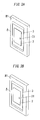
- the vertical and horizontal directions are those of Fig. 1A unless otherwise specified, and a front-back direction is a direction perpendicular to the paper surface of Fig. 1A .
- a first direction is a direction perpendicular to the front-back direction (horizontal direction in Fig. 1A )
- a second direction is a direction perpendicular to the front-back direction and the first direction (vertical direction in Fig. 1A ) .
- the switch device A of this embodiment includes a push-button switch 1 (piano switch), a piano handle 2 (operation handle), a decorative plate 3 and a mounting frame 4.
- the push-button switch 1 has a plurality of light emitting diodes (not illustrated) that emits different colors of light.
- the push-button switch 1 has a box 11 combining a body 11a which has a rectangular box shape of which front surface is open, and a cover 11b which has a rectangular box shape of which rear surface is open.
- a push-button 12, for switching ON/OFF of a contact (not illustrated) enclosed inside, is disposed to the right on the front surface side of the box 11.
- a red light emitting diode and a green light emitting diode (both not illustrated) that turn ON or OFF corresponding to the ON/OFF state of the contact are disposed to the left on the front surface side of the box 11 as well.
- the light emitting diodes of the push-button switch 1 are the red light emitting diode and the green light emitting diode which emit different colors of light in this embodiment, and the light is emitted from the red light emitting diode or the green light emitting diode corresponding to the ON/OFF state push-button switch 1.
- the combination of the light emitting diodes is not limited to the combination of the red light emitting diode and the green light emitting diode, but may be a combination of a red light emitting diode or a green light emitting diode and a light emitting diode that emits a color of light other than red and green.
- a combination of light emitting diodes that emit a color of light different from red and green may be used.
- This push-button switch 1 has a configuration that is similar to the push-button switch of the above mentioned switch device according to Document 1, hence detailed description thereof is omitted.
- the contacts are connected in series between a power supply (not illustrated) and a load (not illustrated), so that power is supplied from the power supply to the load when the contact is turned ON, and the power from the power supply to the load is shut OFF when the contact is turned OFF.
- the piano handle 2 is formed into a rectangular plate shape which is long in the vertical direction, as illustrated in Fig. 1A , and one end of the piano handle 2 (left side in Fig. 2A ) in the horizontal direction is rotatably supported by the push-button switch 1.
- the push-button 12 of the push-button switch 1 is pressed down (see Fig. 2B ).
- the mounting structure of the piano handle 2 is also similar to the switch device disclosed in the above mentioned Document 1, hence detailed description is omitted.
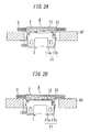
- the decorative plate 3 is formed in a rectangular plate shape which is long in the vertical direction, as illustrated in Fig. 1A , and a window hole 31, which exposes the piano handle 2 to the front surface side, is disposed approximately at the center of the decorative plate 3 (see Fig. 2A and Fig. 2B ).
- the decorative plate 3 is mounted on the later mentioned mounting frame 4 from the front surface side, using an appropriate mounting means, such as mounting screws.
- the mounting frame 4 is a mounting frame for embedded wiring devices standardized by JIS, for example, and has a configuration similar to the mounting frame used for the switch device disclosed in the above mentioned Document 1, hence detailed description thereof is omitted.
- an indication window 21 (indicator) is disposed approximately at the center in the vertical direction and at the right end in the horizontal direction of the piano handle 2 (see Fig. 1A ), and the light from the above mentioned red light emitting diode or the green light emitting diode is guided to the indication window 21 via a light guide (not illustrated).
- the contact (not illustrated) of the push-button switch 1 when the contact (not illustrated) of the push-button switch 1 is turned ON, the power is supplied from the power supply to the load and the red light emitting diode is turned ON, and when the contact is turned OFF, the power from the power supply to the load is shut OFF and the green light emitting diode is turned ON.
- the red light or the green light is emitted from the indication window 21 of the piano handle 2 corresponding to the ON/OFF state of the contact.
- the indication window 21 is disposed in the pressing region of the piano handle 2, and the operating position can be easily recognized by the red light or the green light emitted from this indication window 21.
- Fig. 2A and Fig. 3A show a state of the piano handle 2 not being operated, and in this case, the height of the front surface of the piano handle 2 from the front surface of the decorative plate 3 is approximately the same throughout the entire surface in the front-back direction (vertical direction in Fig. 2A ).
- appearance is better compared with the case of one side of the switch device protruding, as in the case of the switch device disclosed in the above mentioned Document 1.
- the push-button 12 is pressed to the rear by pressing the piano handle 2 to the rear, as illustrated in Fig. 2B and Fig. 3B , whereby the contact is switched to ON or OFF.
- the red light emitting diode or the green light emitting diode is turned ON corresponding to the state of the contact, that is, corresponding to the operating state of the load, and the red light or the green light is emitted toward the front surface side through the indication window 21.
- the front surface of the piano handle 2 protrudes from the front surface of the decorative plate 3, but the front surface of the piano handle 2 and the front surface of the decorative plate 3 may be on a same plane.
- the configuration of the indicator is not limited to this embodiment, but may be another configuration only if the operating position of the piano handle 2 can be recognized thereby.
- the switch device of this embodiment includes the push-button switch 1, the piano handle 2 and the decorative plate 3.
- the ON/OFF of the contact of the push-button switch 1 is switched by the pressing operation of the push-button 12 disposed on the front surface thereof.
- One end of the piano handle 2 is rotatably supported by the push-button switch 1, and the piano handle 2 presses the push-button 12 down when the other end thereof is pressed down.
- the decorative plate 3 has a window hole 31 for exposing the piano handle 2 to the front surface side thereof, and is disposed in front of the push-button switch 1 in a state of the piano handle 2 being exposed to the front surface side through the window hole 31.
- the height of the front surface of the piano handle 2 from the front surface of the decorative plate 3 in the state of the piano handle 2 not being operated is approximately the same throughout the entire surface.
- the indication window 21 (indicator) that indicates the ON/OFF state of the push-down switch 1 is disposed in the pressing region of the piano handle 2.
- the indicator is constituted by the indication window 21 that emits light having different colors corresponding to the ON/OFF state of the push-button switch 1 toward the front surface side using a plurality of light emitting diodes which emit light of different colors.
- the ON/OFF state of the push-button switch 1 is displayed corresponding to the color of the light that is emitted toward the front surface side through the indication window 21.
- the front surface of the piano handle 2 and the front surface of the decorative plate 3 are on a same plane in the state of the piano handle 2 not being operated.
- the front surface of the piano handle 2 protrudes forward from the front surface of the decorative plate 3 in the state of the piano handle 2 not being operated.
Landscapes
- Rotary Switch, Piano Key Switch, And Lever Switch (AREA)
- Switch Cases, Indication, And Locking (AREA)
Applications Claiming Priority (2)
| Application Number | Priority Date | Filing Date | Title |
|---|---|---|---|
| JP2012271896A JP2014120206A (ja) | 2012-12-13 | 2012-12-13 | スイッチ装置 |
| PCT/JP2013/005798 WO2014091651A1 (fr) | 2012-12-13 | 2013-09-28 | Dispositif de commutation |
Publications (2)
| Publication Number | Publication Date |
|---|---|
| EP2933814A1 true EP2933814A1 (fr) | 2015-10-21 |
| EP2933814A4 EP2933814A4 (fr) | 2015-12-30 |
Family
ID=50933965
Family Applications (1)
| Application Number | Title | Priority Date | Filing Date |
|---|---|---|---|
| EP13863084.3A Withdrawn EP2933814A4 (fr) | 2012-12-13 | 2013-09-28 | Dispositif de commutation |
Country Status (7)
| Country | Link |
|---|---|
| EP (1) | EP2933814A4 (fr) |
| JP (1) | JP2014120206A (fr) |
| KR (1) | KR20150041102A (fr) |
| CN (1) | CN104620346A (fr) |
| PH (1) | PH12015500343A1 (fr) |
| TW (1) | TWI549149B (fr) |
| WO (1) | WO2014091651A1 (fr) |
Family Cites Families (17)
| Publication number | Priority date | Publication date | Assignee | Title |
|---|---|---|---|---|
| JPS61173428A (ja) * | 1985-01-25 | 1986-08-05 | 松下電工株式会社 | スイツチ装置 |
| JPS61201224U (fr) * | 1985-06-05 | 1986-12-17 | ||
| JP2513852Y2 (ja) * | 1990-01-26 | 1996-10-09 | 松下電工株式会社 | ピアノハンドル式スイッチ |
| JP3020252B2 (ja) * | 1990-05-02 | 2000-03-15 | 松下電工株式会社 | ピアノハンドル式スイッチ |
| JPH0613030U (ja) * | 1991-04-26 | 1994-02-18 | アルパイン株式会社 | 押釦装置 |
| JPH05325724A (ja) * | 1992-05-26 | 1993-12-10 | Matsushita Electric Works Ltd | 接点切換表示機能付ピアノスイッチ |
| DE19737907B4 (de) * | 1997-09-01 | 2007-10-18 | Abb Patent Gmbh | Tastschalteranordnung |
| JP2001176354A (ja) | 1999-12-22 | 2001-06-29 | Matsushita Electric Works Ltd | ピアノハンドル式片切スイッチ装置 |
| JP3685101B2 (ja) * | 2001-07-26 | 2005-08-17 | 松下電工株式会社 | 配線器具システム |
| JP4228743B2 (ja) * | 2003-03-26 | 2009-02-25 | パナソニック電工株式会社 | スイッチ |
| JP2006331999A (ja) * | 2005-05-30 | 2006-12-07 | Toyoda Gosei Co Ltd | 揺動スイッチ |
| JP4626567B2 (ja) * | 2006-05-12 | 2011-02-09 | パナソニック電工株式会社 | 操作スイッチ器具 |
| US8641250B2 (en) * | 2007-06-07 | 2014-02-04 | Johnson Controls Technology Company | Illuminated component for a vehicle |
| JP4627550B2 (ja) * | 2008-01-11 | 2011-02-09 | レノボ・シンガポール・プライベート・リミテッド | 押ボタン装置及び電子機器 |
| CN201259857Y (zh) * | 2008-09-12 | 2009-06-17 | 浙江正泰建筑电器有限公司 | 大范围快速接线的摆动式墙壁开关 |
| CN201570417U (zh) * | 2009-11-23 | 2010-09-01 | 中山品上照明有限公司 | 一种纯平按钮开关 |
| FR2966971B1 (fr) * | 2010-11-02 | 2012-10-26 | Legrand France | Appareillage electrique a fonction lumineuse. |
-
2012
- 2012-12-13 JP JP2012271896A patent/JP2014120206A/ja active Pending
-
2013
- 2013-09-28 CN CN201380046642.9A patent/CN104620346A/zh active Pending
- 2013-09-28 KR KR1020157006003A patent/KR20150041102A/ko not_active Ceased
- 2013-09-28 WO PCT/JP2013/005798 patent/WO2014091651A1/fr not_active Ceased
- 2013-09-28 EP EP13863084.3A patent/EP2933814A4/fr not_active Withdrawn
- 2013-12-04 TW TW102144448A patent/TWI549149B/zh active
-
2015
- 2015-02-17 PH PH12015500343A patent/PH12015500343A1/en unknown
Also Published As
| Publication number | Publication date |
|---|---|
| TW201435943A (zh) | 2014-09-16 |
| WO2014091651A1 (fr) | 2014-06-19 |
| KR20150041102A (ko) | 2015-04-15 |
| CN104620346A (zh) | 2015-05-13 |
| EP2933814A4 (fr) | 2015-12-30 |
| PH12015500343A1 (en) | 2015-04-20 |
| JP2014120206A (ja) | 2014-06-30 |
| TWI549149B (zh) | 2016-09-11 |
Similar Documents
| Publication | Publication Date | Title |
|---|---|---|
| US9355794B2 (en) | Push-type switch with display | |
| GB2487928A (en) | Display device for displaying two overlapping graphics independently, in particular on a push button type switch. | |
| US20120061227A1 (en) | Structure of press switch | |
| WO2015145957A1 (fr) | Dispositif de commutation | |
| JP5580728B2 (ja) | 小型電気機器 | |
| US20140190804A1 (en) | Luminous press key module | |
| JP2009199896A (ja) | タッチスイッチ装置 | |
| EP2933814A1 (fr) | Dispositif de commutation | |
| JP2014194848A (ja) | スイッチ構造 | |
| WO2015145960A1 (fr) | Dispositif de commutateur | |
| JP2012099374A (ja) | 操作パネル | |
| JP6355051B2 (ja) | 配線器具用取付枠、操作ハンドル、及びスイッチ装置 | |
| KR100543752B1 (ko) | 차량용 스위치 구조 | |
| JP2009220929A (ja) | エレベータの防滴型押しボタンスイッチ | |
| KR101313678B1 (ko) | 로고 발광을 위한 광원 조립체 및 발광 로고를 구비하는 전자제품 | |
| TWI864375B (zh) | 配線器具 | |
| WO2015145958A1 (fr) | Dispositif de commutation et système de commande de charge | |
| JP2006302555A (ja) | 押しボタン装置およびこれを用いた電話装置 | |
| KR102668830B1 (ko) | 디바이스 | |
| JP2020140132A (ja) | 表示装置 | |
| JP6174324B2 (ja) | 携帯電子機器用入力装置および携帯電子機器 | |
| KR20100005792U (ko) | 엘이디 조명이 내장된 버튼 | |
| JP5473142B2 (ja) | 狭額縁表示装置付き押ボタンスイッチ | |
| CN107644768B (zh) | 开关 | |
| US20100172139A1 (en) | Plate for Inscription |
Legal Events
| Date | Code | Title | Description |
|---|---|---|---|
| PUAI | Public reference made under article 153(3) epc to a published international application that has entered the european phase |
Free format text: ORIGINAL CODE: 0009012 |
|
| 17P | Request for examination filed |
Effective date: 20150220 |
|
| AK | Designated contracting states |
Kind code of ref document: A1 Designated state(s): AL AT BE BG CH CY CZ DE DK EE ES FI FR GB GR HR HU IE IS IT LI LT LU LV MC MK MT NL NO PL PT RO RS SE SI SK SM TR |
|
| AX | Request for extension of the european patent |
Extension state: BA ME |
|
| A4 | Supplementary search report drawn up and despatched |
Effective date: 20151126 |
|
| RIC1 | Information provided on ipc code assigned before grant |
Ipc: H01H 9/02 20060101ALI20151120BHEP Ipc: H01H 21/00 20060101AFI20151120BHEP Ipc: H01H 23/02 20060101ALI20151120BHEP Ipc: H01H 21/02 20060101ALI20151120BHEP Ipc: H01H 9/16 20060101ALI20151120BHEP |
|
| DAX | Request for extension of the european patent (deleted) | ||
| 17Q | First examination report despatched |
Effective date: 20170510 |
|
| STAA | Information on the status of an ep patent application or granted ep patent |
Free format text: STATUS: THE APPLICATION HAS BEEN WITHDRAWN |
|
| 18W | Application withdrawn |
Effective date: 20170907 |