EP2934268B1 - Brosse de nettoyage pour un appareil de nettoyage de sol et appareil de nettoyage de sol avec une brosse de nettoyage - Google Patents
Brosse de nettoyage pour un appareil de nettoyage de sol et appareil de nettoyage de sol avec une brosse de nettoyage Download PDFInfo
- Publication number
- EP2934268B1 EP2934268B1 EP12809790.4A EP12809790A EP2934268B1 EP 2934268 B1 EP2934268 B1 EP 2934268B1 EP 12809790 A EP12809790 A EP 12809790A EP 2934268 B1 EP2934268 B1 EP 2934268B1
- Authority
- EP
- European Patent Office
- Prior art keywords
- brush
- cleaning
- floor cleaner
- bearing
- accordance
- Prior art date
- Legal status (The legal status is an assumption and is not a legal conclusion. Google has not performed a legal analysis and makes no representation as to the accuracy of the status listed.)
- Active
Links
Images




Classifications
-
- A—HUMAN NECESSITIES
- A47—FURNITURE; DOMESTIC ARTICLES OR APPLIANCES; COFFEE MILLS; SPICE MILLS; SUCTION CLEANERS IN GENERAL
- A47L—DOMESTIC WASHING OR CLEANING; SUCTION CLEANERS IN GENERAL
- A47L11/00—Machines for cleaning floors, carpets, furniture, walls, or wall coverings
- A47L11/40—Parts or details of machines not provided for in groups A47L11/02 - A47L11/38, or not restricted to one of these groups, e.g. handles, arrangements of switches, skirts, buffers, levers
- A47L11/4036—Parts or details of the surface treating tools
- A47L11/4041—Roll shaped surface treating tools
-
- A—HUMAN NECESSITIES
- A47—FURNITURE; DOMESTIC ARTICLES OR APPLIANCES; COFFEE MILLS; SPICE MILLS; SUCTION CLEANERS IN GENERAL
- A47L—DOMESTIC WASHING OR CLEANING; SUCTION CLEANERS IN GENERAL
- A47L11/00—Machines for cleaning floors, carpets, furniture, walls, or wall coverings
- A47L11/40—Parts or details of machines not provided for in groups A47L11/02 - A47L11/38, or not restricted to one of these groups, e.g. handles, arrangements of switches, skirts, buffers, levers
- A47L11/4063—Driving means; Transmission means therefor
- A47L11/4069—Driving or transmission means for the cleaning tools
-
- A—HUMAN NECESSITIES
- A47—FURNITURE; DOMESTIC ARTICLES OR APPLIANCES; COFFEE MILLS; SPICE MILLS; SUCTION CLEANERS IN GENERAL
- A47L—DOMESTIC WASHING OR CLEANING; SUCTION CLEANERS IN GENERAL
- A47L9/00—Details or accessories of suction cleaners, e.g. mechanical means for controlling the suction or for effecting pulsating action; Storing devices specially adapted to suction cleaners or parts thereof; Carrying-vehicles specially adapted for suction cleaners
- A47L9/02—Nozzles
- A47L9/04—Nozzles with driven brushes or agitators
- A47L9/0427—Gearing or transmission means therefor
- A47L9/0444—Gearing or transmission means therefor for conveying motion by endless flexible members, e.g. belts
-
- A—HUMAN NECESSITIES
- A47—FURNITURE; DOMESTIC ARTICLES OR APPLIANCES; COFFEE MILLS; SPICE MILLS; SUCTION CLEANERS IN GENERAL
- A47L—DOMESTIC WASHING OR CLEANING; SUCTION CLEANERS IN GENERAL
- A47L9/00—Details or accessories of suction cleaners, e.g. mechanical means for controlling the suction or for effecting pulsating action; Storing devices specially adapted to suction cleaners or parts thereof; Carrying-vehicles specially adapted for suction cleaners
- A47L9/02—Nozzles
- A47L9/04—Nozzles with driven brushes or agitators
- A47L9/0455—Bearing means therefor
-
- A—HUMAN NECESSITIES
- A47—FURNITURE; DOMESTIC ARTICLES OR APPLIANCES; COFFEE MILLS; SPICE MILLS; SUCTION CLEANERS IN GENERAL
- A47L—DOMESTIC WASHING OR CLEANING; SUCTION CLEANERS IN GENERAL
- A47L9/00—Details or accessories of suction cleaners, e.g. mechanical means for controlling the suction or for effecting pulsating action; Storing devices specially adapted to suction cleaners or parts thereof; Carrying-vehicles specially adapted for suction cleaners
- A47L9/02—Nozzles
- A47L9/04—Nozzles with driven brushes or agitators
- A47L9/0461—Dust-loosening tools, e.g. agitators, brushes
- A47L9/0466—Rotating tools
- A47L9/0477—Rolls
-
- A—HUMAN NECESSITIES
- A47—FURNITURE; DOMESTIC ARTICLES OR APPLIANCES; COFFEE MILLS; SPICE MILLS; SUCTION CLEANERS IN GENERAL
- A47L—DOMESTIC WASHING OR CLEANING; SUCTION CLEANERS IN GENERAL
- A47L2201/00—Robotic cleaning machines, i.e. with automatic control of the travelling movement or the cleaning operation
Definitions
- the disclosure relates to a cleaning brush for a floor cleaning appliance, in particular a self-propelled and self-steering floor cleaning appliance comprising at least one brush unit having a brush body defining a brush axis and provided with cleaning bristles brush body having a first end and a second end, wherein the at least one brush unit at the first end or in the region of the first end has a torque receiving device for coupling with a drive device of the floor cleaning device.
- the invention relates to a floor cleaning device with a cleaning brush, in particular a self-propelled and self-steering floor cleaning device.
- the DE 10 2007 006 654 A1 describes a cleaning head for a floor cleaning device and a cleaning brush included therein.
- a drive means for driving two brush units of the cleaning brush is arranged, which has a longitudinally extending axial and rotatable shaft.
- the brush units are attached to the drive shaft, which engages over almost the entire length in the brush body.
- a torque receiving device arranged at the first end of the respective brush unit couples with a driver of the shaft as part of the drive device.
- a cleaning brush described whose construction similar to that in the DE 10 2007 006 654 A1 cleaning brush is described.
- two brush units are used, which are arranged on different sides of a centrally arranged drive device of a floor cleaning device.
- the brush units have respective positive engagement formations which couple with each other and with the drive means.
- the form-fitting of a first brush unit is screwed via an external thread with an internal thread of a drive shaft and is provided blind hole-like provided with an internal thread.
- the form-fitting formation of the second brush unit carries an external thread and is screwed to the internal thread.
- the US 4,222,146 describes a suction device with a cleaning brush, which is centrally driven by a belt and stored off-center.
- Object of the present invention is to provide a generic cleaning brush and a floor cleaning device, the reliable support on the floor cleaning device is possible in a structurally simple manner.
- This object is achieved in a generic cleaning brush, characterized in that the at least one brush unit has a bearing means for storing the floor cleaning device, which is arranged between the first end and the second end, and that the brush units are separated from each other connected to the floor cleaning device and released from this can.
- a bearing device is used which, with respect to the brush axis, is arranged axially between the first end and the second end and thus at a distance from the second end on the brush body.
- the bearing device makes it possible to rotatably support the at least one brush unit and to support it via a section arranged radially outside the brush body on the floor cleaning device.
- a torque exerted by the drive means is applied to the brush body via the torque receiving means at the first end transfer.
- a support of the at least one brush unit spatially limited to the floor cleaning device, namely on the one or in the region of the first end of the drive device and on the other via the bearing device at a distance from the second end.
- the at least one brush unit at the second end is free of a bearing device for storage on the floor cleaning device, which is made possible for example by the arrangement of the bearing device at a distance from the second end. This makes it possible, for example, to achieve an improved cleaning result by standing over the second end cleaning bristles, which will be discussed below.
- the bearing device has a distance from the first end, which corresponds to about 50% to about 70% of the length of the brush body, preferably about 60%.
- the brush body is provided with cleaning bristles on both sides of the bearing device and if arranged on opposite sides of the bearing device and this adjacent cleaning bristles have an axial inclination with respect to the brush axis in the direction of the other side of the bearing device.
- Cleaning bristles disposed on opposite sides of the storage facility are inclined, wherein they are aligned in the direction of the other side of the bearing device. This makes it possible to remove dirt from the floor surface to be cleaned even in the area of the bearing device by means of the inclined cleaning bristles.
- sweeping mirrors are adjacent to one another or overlapping one another on a floor surface to be cleaned of the cleaning bristles of mutually opposite sides of the bearing device.
- the inclined cleaning bristles on opposite sides of the bearing device intersect or cross each other assuming that they occupy the same angular position in the circumferential direction of the brush axis.
- the sweeping mirror defines the area covered by the cleaning brush and thus cleaned.
- the sweeping mirrors of the inclined cleaning bristles on opposite sides of the bearing device adjoin one another or overlap one another, so that streak-free cleaning of the bottom surface using the cleaning brush is also possible in the region of the bearing device.
- the sweeping mirrors adjoin one another or overlap one another in the direction of the floor surface to be cleaned.
- the cleaning bristles have an axial inclination with respect to the brush axis at or near the first end and / or the second end and protrude beyond the first end or over the second end of the brush body. This makes it possible to clean with the cleaning brush and portions of the bottom surface, which are arranged laterally adjacent to the first end and / or the second end. As a result of the cleaning bristles having the inclination, the sweeping mirror of the cleaning brush projects beyond the first end or beyond the second end. At the second end this proves to be particularly advantageous if the at least one brush unit, as mentioned above, at the second end is free of a bearing device. At the first end, the bottom surface can also be cleaned below the drive device, which is arranged laterally next to the first end, when the inclined cleaning bristles protrude below the drive device.
- the torque receiving device comprises a recess arranged in the brush body at the first end for a corresponding drive element of the drive device.
- the drive element can in particular engage in a form-fitting manner in the recess in order to transmit a torque to the brush body.
- the brush body is divided axially into a first brush body segment forming the first end and a second brush body segment forming the second end, which is connected to the first brush body segment.
- the connection is preferably rotationally fixed to one another in order to transmit torque from the first brush body segment to the second brush body segment.
- the brush body segments are connected to one another on the bearing device and if the bearing device is arranged axially between the brush body segments. It turns out in practice that thereby a compact design of the at least one brush unit can be achieved.
- the brush body for connecting the brush body segments on each rotatably engaging in this torque transmission member, which passes through the bearing means.
- a torque can be transmitted from the first to the second brush body segment.
- the bearing of the brush body can be done on the traversed by the torque transmitting member bearing device.
- the torque transmitting member is configured, for example, as engaging in the brush body segments shaft.
- the bearing device comprises a bearing body and, based on the brush axis, comprises or forms a radial bearing, and if the bearing body has a bearing portion which is mounted on the radial bearing on the brush body, and a fixing portion connected to the fixing portion on which at least one fixing member is arranged for fixing to the floor cleaning device.
- a radial bearing of the brush body for example of the torque transmitting member - preferably the shaft mentioned above - can be done on the bearing portion of the bearing body via the radial bearing.
- the fixing section it is possible to fix the bearing body and thus the at least one brush unit on the floor cleaning device.
- the at least one fixing member is arranged radially outside of the brush body, wherein it may be connected, for example, with a wall of a brush receiving space of the floor cleaning device, in which the cleaning brush is arranged.
- the radial bearing is designed as a ball bearing.
- the ball bearing is arranged, for example, radially between the bearing portion and the brush body or its torque transmitting member.
- the radial bearing is designed as a sliding bearing. It is conceivable that the bearing portion is slidably mounted on the brush body or its torque transmitting member.
- the bearing body comprises at least one spring member, via which the bearing portion axially and / or radially spring-mounted on the fixing.
- the at least one spring member allows axial suspension. This makes it possible to apply the brush body in the direction of the drive device. As a result, their reliable rotationally fixed connection can be ensured with the torque receiving device, wherein axial play and tolerances are compensated.
- a radial suspension of the at least one brush unit allows, for example, to compensate for uneven floors. Conversely, radial movements of the at least one brush unit are not transmitted or only attenuated to the fixing section. The support of the at least one brush unit on the floor cleaning device is thereby exposed to lower forces.
- bearing portion and the fixing portion interconnecting spring bars are provided as spring members.
- connect the spring bars a bearing portion annularly surrounding fixing.
- the at least one fixing member comprises a latching element or forms for latching with a corresponding latching element of the floor cleaning device.
- the fixing member is, for example, a locking projection which cooperates with a corresponding locking receptacle on the floor cleaning device.
- the locking projection is designed, for example hook-shaped, to fix the bearing body hanging on a wall of the brush receiving space of the floor cleaning device.
- the at least one fixing member for forming a rotary closure with the floor cleaning device is configured, for example in the manner of a bayonet connection, wherein the fixing member can be inserted into a receptacle on the floor cleaning device and fixed by turning the receptacle.
- the bearing body is in one piece to allow a structurally simple embodiment of the cleaning brush.
- the bearing body is at least partially configured plate-shaped.
- the fixing portion of the bearing body is designed plate-shaped.
- the cleaning brush comprises two brush units.
- the brush units are in particular configured as described above using the example of the at least one brush unit of the cleaning brush and advantageous embodiments thereof.
- Both cleaning brushes can preferably be connected separately to the drive device and fixed and stored on the respective storage device on the floor cleaning device.
- the brush units are particularly preferred, based on coincident brush axes of the same, symmetrically or substantially symmetrically relative to each other configured with respect to a plane of symmetry which is aligned perpendicular to the brush axes of the brush units.
- the plane of symmetry is arranged between the respective first ends of the brush units, on which the drive device can be arranged when the cleaning brush is used on the floor cleaning device.
- the brush units can deviate from a symmetry, for example with regard to their cleaning bristles.
- An inventive floor cleaning device is in particular a self-propelled and self-steering floor cleaning device. It comprises a housing which forms a brush receiving space, a cleaning brush of the type described above, which has two brush units, arranged in the brush receiving space, and a cleaning brush drive device which is provided at the first end of the brush body of the respective brush unit with its torque receiving device coupled and the respective brush unit rotatably drives, wherein the brush units can be separated from each other connected to the floor cleaning device and released from it.
- the brush axis is, for example, a transverse axis aligned transversely to the main direction of movement of the floor cleaning appliance.
- the drive device comprises a drive element which can be driven in rotation about the brush axis and which engages in a corresponding recess of the brush body.
- a drive element which can be driven in rotation about the brush axis and which engages in a corresponding recess of the brush body.
- the drive device comprises a drive motor outside the brush receiving space and a cooperating with this torque transfer device, which is arranged in the brush receiving space and coupled to the torque receiving device of the respective brush unit.
- the preferably device-fixed drive device comprises the drive motor, in particular an electric motor. To protect against dirt, this is arranged outside of the brush receiving space.
- the drive device may have a transmission device for driving the torque transmission device, which couples in the brush receiving space with the torque receiving device.
- the floor cleaning device comprises or forms at least one fixing element on or in the brush receiving space, which has a fixing element the bearing device of the respective brush unit for fixing the cleaning brush on the floor cleaning device cooperates.
- the cooperating fixing members make it possible to fix the respective brush unit via the bearing device on the floor cleaning device.
- the at least one fixing member of the floor cleaning appliance is preferably encompassed or formed by a wall of the brush receiving space.
- the at least one fixing member of the floor cleaning appliance comprises or forms a latching element for latching with a corresponding latching element of the cleaning brush.
- the fixing member is a latching receptacle on which a latching projection of the bearing device is locked.
- the latching receptacle is designed, for example, slit-shaped, so that the bearing device and thus the respective brush unit can be fixed in a hanging manner on a wall of the brush accommodating space via a hook-shaped latching projection.
- the at least one fixing member of the floor cleaning device is designed to form a rotary closure with the fixing member of the cleaning brush, for example in the manner of a bayonet connection.
- the cleaning brush is releasably connectable with the floor cleaning device incidentally.
- the first end of the respective brush unit can be placed on the drive device, for example in the axial or substantially axial direction.
- a drive element of the drive device engage in a corresponding recess at the first end.
- the bearing device can be locked with a wall of the brush receiving space.
- the respective brush unit is then held on the floor cleaning device via the bearing device and the coupling with the drive device.
- the locking of the bearing device with the wall of the brush receiving space can be solved and then the respective brush unit are removed in a direction away from the drive device direction.
- the cleaning brush can be fixed manually and / or without tools to the floor cleaning appliance or can be detached therefrom.
- the cleaning brush comprises two brush units. Their brush axes can coincide, wherein the drive means is arranged at least partially axially between the brush units.
- the two brush units can couple sides facing away from one another with the drive device, wherein their torque receiving devices can interact with a torque transmission device of the drive device.
- the two brush units are preferably configured symmetrically with respect to a plane of symmetry aligned perpendicular to the brush axes.
- the cleaning bristles of the brush units which are arranged at or near the respective first ends, have an axial inclination and protrude beyond the respective first ends in the direction of the respective other brush unit, and if sweeping on a floor surface to be cleaned of the cleaning bristles both brush units adjacent to each other or overlap each other.
- Cleaning bristles of the brush units protrude from their respective first end toward the other brush unit. This makes it possible to clean a floor surface in the area of the drive device with the cleaning bristles.
- the sweeping levels of the respectively inclined cleaning bristles adjoin one another or preferably overlap. This makes it possible to achieve a streak-free cleaning of the bottom surface also in the area of the drive device with the cleaning brush.
- the sweeping mirrors adjoin one another in an unloaded state of the cleaning brush in the direction of the floor surface to be cleaned or overlap.
- the housing comprises or forms brush covers which at least partially overlap the respective second ends of the brush bodies, the brush covers preferably completely or substantially completely covering the cleaning bristles on the front side.
- the brush covers serve to protect existing obstacles in the room to be cleaned from contact with the rotating cleaning brush, for example curtains or curtains, which could be caught, wound up and damaged by the cleaning brush.
- At least one brush cover is designed to be movable relative to the housing and from a bristle cover position in which the brush cover laterally projects beyond the brush axis cleaning bristles, which are arranged at or near the second end of the brush unit facing it, along the brush axis Bristle release parting in which the cleaning bristles protrude laterally beyond the brush cover along the brush axis, and vice versa.
- This allows in particular the improvement of a cleaning of edge areas of a room to be cleaned, as described in detail in the non-prepublished patent application DE 10 2012 104 326.4 the same applicant is described.
- This patent application is incorporated herein by reference, and its contents fully incorporated in the present application.
- the cleaning bristles at the second end can project laterally beyond the brush cover. Part of the cleaning bristles can in this way with the free bristle ends outside of the floor cleaning device protrude, especially on its base. As a result, hard-to-clean edges and corners can be effectively cleaned.
- the brush cover In the bristle cover position, the brush cover overhangs the cleaning bristles to protect obstacles from contact with the cleaning brush as discussed above.
- the brush cover is transferred from the bristle cover position into the bristle release position, for example, under the application of force in the direction of the second end of the adjacent brush unit.
- the cleaning brush at the second end is free from a bearing device, so that the brush cover can be moved as close as possible to the second end.
- Both brush covers are preferably each movable from a bristle cover position into a bristle release position and vice versa.
- the at least one movable brush cover is displaceable relative to the cleaning brush on the housing in order to transfer it from the bristle cover position into the bristle release position and vice versa.
- the at least one movable brush cover is arranged on the outside of the housing and in the bristle cover position, preferably also in the bristle release part, forms the outer contour of the housing in sections.
- the brush cover can contact an obstacle such as in particular an edge or wall and can be transferred as a result of the contact of the bristle cover position in the direction of its bristle release position.
- the brush cover also forms a portion of the outer contour in the bristle release parting so that permanent contact with an obstruction can be maintained while cleaning bristles protrude beyond the brush cover to allow cleaning along the edge or wall.
- the floor cleaning device can be self-propelled and self-steering designed to allow autonomous cleaning of a floor surface.
- the floor cleaning appliance has no further abrasive cleaning tools beyond the at least one cleaning brush, especially no additional turning units with cleaning bristles projecting beyond a base area of the floor cleaning appliance.
- FIG. 1 shows in perspective view a total occupied by the reference numeral 10 advantageous embodiment of a floor cleaning device according to the invention.
- the floor cleaning device 10 is a self-propelled and self-steering floor cleaning device and designed as a so-called "cleaning robot" with which a bottom surface 12 can be cleaned autonomously.
- the floor cleaning apparatus 10 has a front side 14, a left side 15 and a right side 16.
- Positioning and orientation indications such as “front”, “top”, “bottom”, “horizontal” and “vertical” are presently considered to be based on a proper use of the floor cleaning appliance 10, in which this is positioned on the assumed as horizontal bottom surface 12 , as well as with respect to a longitudinal or main direction of movement 18 of the floor cleaning device 10.
- a housing 20 forms near the front side 14 a brush receiving space 22 for a cleaning brush 24, which in the present case is a preferred embodiment of a cleaning brush.
- the brush receiving space 22 extends in the transverse direction over the entire width of the floor cleaning device 10.
- brush covers 26 and 27 on the left side 15 and right side 16 limit the brush receiving space 22 laterally and thereby cover end sides of the cleaning brush 24, which will be discussed below.
- the brush covers 26 and 27 are arranged on the outer contour of the floor cleaning device 10 and form an outer lateral boundary thereof.
- the brush receiving space 22 is bounded by a wall 28 in the direction of the front 14, on the top and in sections to the rear.
- the wall 28 is formed by a supporting chassis 29 of the housing 20.
- an opening 30 is formed in the wall 28. Through the opening 30 can with the cleaning brush 24 swept away from the bottom surface 12 dirt swept into a dirt collector 32 of the floor cleaning device 10 and deposited therein. This is done under the complementary effect of a suction unit, not shown in the drawing of the floor cleaning device 10th
- the floor cleaning appliance 10 Located slightly upstream of the opening 30 in the longitudinal direction 18, the floor cleaning appliance 10 comprises a guide element 34 rising obliquely from the front to the rear for dirt facing away from the floor surface 12.
- the dirt can be transported via the guide element 34 in the direction of the opening 30, so that the guide element 34 forms a sweeping edge for sweeping up dirt. It extends over almost the entire width of the floor cleaning device 10 in the brush receiving space 22.
- the cleaning brush 24 extends substantially the entire width of the floor cleaning device 10 between the brush covers 26 and 27 and is oriented transversely to the longitudinal direction 18, wherein it defines a brush axis 36.
- the brush axis 36 is parallel to the bottom surface 12 and horizontal.
- the cleaning brush 24 is rotatably driven about the brush axis 36 as explained below, wherein the cleaning brush 24 returns dirt after the "dustpan" principle to the rear over the guide member 34.
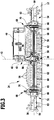
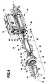
- To drive the cleaning brush 24 includes the floor cleaning device 10 in the Figures 3 and 4 shown drive device 38.
- the drive device 38 has a arranged in a motor housing 40 drive motor 41, which is designed here as an electric motor.
- the drive motor 41 is supplied by not shown in the drawing batteries of the floor cleaning device 10 with electrical energy.
- the motor housing 40 is connected at a central longitudinal plane 42 of the floor cleaning device 10 to a transmission housing 43 of the drive device 38, in which a transmission device 44 is arranged.
- the view of the transmission device 44 is in FIG. 4 released, in which a half-shell-shaped cover 45 of the gear housing 43 ( FIG. 3 ) is not shown.
- the gear mechanism 44 comprises a toothed wheel 46 which is connected in a rotationally fixed manner to a shaft of the drive motor 41 and which drives a toothed belt 47 which rotatably drives a further toothed wheel 48 in the brush receiving space 22.
- a torque transmitting device 49 is coupled, comprising a rotatably connected to the gear 48 and the transmission housing 43 by cross drive shaft 50 and two rotatably connected to these drive elements 51.
- the drive elements 51 are arranged on opposite sides outside of the transmission housing 43 (only one is in FIG. 4 shown). An axis of the drive shaft 50 is aligned with the brush axis 36th
- the drive device 38 is fixed to the device. It is fixed to the chassis 29, via the motor housing 40, which is arranged as well as an upper portion of the gear housing 43 outside of the brush receiving space 22.
- the motor housing 40 is positioned to the right side of the central longitudinal plane 42. A lower portion of the transmission case 43 and the torque transmitting device 49 are disposed in the brush accommodating space 22.
- the cleaning brush 24 comprises two brush units 52 and 54, wherein the brush unit 52 is arranged on the left and the brush unit 54 on the right side of the central longitudinal plane 42. Both brush units 52, 54 define the common brush axis 36.
- the brush units 52 and 54 are formed substantially symmetrical to each other with respect to a plane of symmetry, which coincides with the central longitudinal plane 42 and is accordingly aligned perpendicular to the brush axis 36. Excluded from the symmetry are the bristles of the brush units 52, 54, wherein the cleaning bristles 56 need not necessarily be arranged symmetrically to each other, although this is of course also possible.
- the brush unit 52 has a first end 58 facing the gear housing 43 and a second end 59 facing the brush cover 26.
- the brush unit 52 further comprises a brush body 60 defining the brush axis 36 and comprising two substantially cylindrical brush body segments 62 and 63. Of these, the brush body segment 62 forms the first end 58 and the brush body segment 63 forms the second end 59. Both brush body segments 62 and 63 are provided with cleaning bristles 56.
- the brush body segments 62, 63 are rotatably connected to each other, via a torque transmitting member of the brush body 60, which is preferably configured as a shaft 64 as in the present case.
- the shaft 64 engages in the other of the brush body segment 62, 63 facing end portions 65, 66 of the brush body segments 62 and 63 and is held against rotation thereon.
- the rotationally fixed connection takes place for example by positive engagement or fixation by means of an additional connecting element.
- the brush unit 52 has for storage and fixation on the floor cleaning device 10 to a bearing means 68 which is disposed axially between the brush body segments 62 and 63 and thus between the ends 58 and 59 of the brush body 60.
- the distance of the bearing means 68 from the first end 58 is approximately 60% of the length of the brush body 60.
- the bearing device 68 is penetrated axially by the shaft 64 and is thereby radially externally placed on this.
- the bearing device 68 comprises a radial bearing, which surrounds the shaft 64 and is configured here as a ball bearing 69, and a bearing body 70, which is mounted on the ball bearing 69 about the brush axis 36 on the shaft 64 and thus on the brush body 60.
- the bearing body 70 comprises a ball bearing 69 surrounding and present ring-shaped bearing portion 71 between the brush body segments 62, 63. Further, the bearing body 70 comprises a fixing portion 72 which surrounds the bearing portion 71 radially and radially outward with respect to the brush body 60 is arranged.
- the fixing portion 72 and the bearing portion 71 are interconnected via axially effective spring members which are configured here as spring webs 73. Overall, three elastically resilient spring webs 73 are provided. These can act on the brush body 60 with a spring force in the direction of the drive means 38 to prevent play with the drive member 51 and ensure a reliable rotationally fixed connection.
- the fixing portion 72 is designed substantially plate-shaped and has at an upper edge, based on a proper use of the cleaning brush 24 with the floor cleaning device 10, a fixing member 74 for fixing the brush unit 52 on the floor cleaning device 10.
- the fixing member 74 is presently a locking element and in particular forms a hook-shaped in the direction of the front side 14 facing locking projection 75th
- the fixing member 74 is associated with a corresponding fixing member 76 of the floor cleaning device 10, which is arranged on the wall 28 of the brush receiving space 22.
- the fixing member 76 includes a locking receptacle 77, in which the latching projection 75 can engage detent.
- the latching receptacle 77 comprises a slot-shaped opening 78 formed in the wall 28.
- the latching projection 75 can be inserted into the opening 78 and latched by a rotational movement at its front edge (FIG. 5).
- the cooperating fixing members 74 and 76 allow in this way, the bearing body 70 and thus the brush unit 52 via a kind of bayonet lock horizontally aligned on the floor cleaning device 10 to fix.
- a manual and tool-free fixation is possible.
- the fixation can be solved manually and without tools by canceling the locking of the fixing members 74 and 76 and thus the bearing body 70 are separated from the floor cleaning device 10.
- projections 79 and 80 are arranged, which protrude from the wall 28 in the brush receiving space 22.
- the projections 79 and 80 take the bearing body 70 at its upper edge substantially free of play between them when it is locked to the wall 28.
- the projections 79 and 80 allow an axial alignment of the bearing body 70 and thus an axial fixation of the brush unit 52.
- the fixing portion 72 comprises a further fixing member 82, which is formed by a kind of wing-shaped projection.
- the fixing member 82 forms a strip-shaped latching projection 83 and can cooperate with fixing members 84 on the guide element 34.
- the fixing members 84 are strip-shaped in the brush receiving space 22 projecting locking projections 85 ( Figures 2 and 5 ).
- the latching projections 85 take the latching projection 83 substantially free of play between them and thereby also allow an axial fixation of the bearing body 70, via a holder and against rotation around the brush axis 36 also.
- the fixing members 82 and 84 can be connected to each other manually and without tools and separated from each other.
- the brush unit 52 has a torque receiving device 86, which comprises a recess 87 formed in the brush body 60 ( FIG. 6 ).
- the recess 87 is formed so that the drive element 51 can engage in a form-fitting manner in order to transmit a torque to the brush unit 52 and to drive it rotationally about the brush axis 36.
- the drive element 51 only engages in the brush body 60 at the end section forming the first end 58, so that the brush unit 52 can be placed on the drive device 38 essentially axially in a simple manner.
- cleaning bristles 56 are further arranged, which have in the direction of the other brush unit 54 an axial inclination.
- the inclination of the cleaning bristles 56 is such that they protrude beyond the first end 58 and thereby engage under the drive device 38 on the gear housing 43.
- the cleaning bristles 56 of both brush units 52, 54 are so long that the sweeping mirrors on the bottom surface 12 overlap each other ( Figures 2 and 3 ).
- the cleaning bristles 56 of the brush units 52, 54 cross each other below the gear housing 43, based on the same rotational angle with respect to the brush axis 36. This allows the bottom surface 12 also below the gear housing 43 with cleaning bristles 56 to detect and clean streak-free.
- the sweeping mirrors of cleaning bristles 56 overlay the end portions 65 and 66 of the brush body segments 62 and 63, respectively.
- the cleaning bristles 56 adjacent to the bearing device 68 each have an inclined position in the direction of the other brush body segment 62, 63 and thus protrude below the bearing device 68 (FIG. FIG. 3 ). Also in the area of the storage device 68, the bottom surface 12 are thereby cleaned free of streaks, because the inclined cleaning bristles 56 contact them.
- cleaning bristles 56 are arranged, which have an inclined position with respect to the brush axis 36, in such a way that the cleaning bristles 56 protrude laterally beyond the second end 59. Thereby, a portion of the bottom surface 12 can be contacted and cleaned by the brush unit 52, which lies axially outside of the brush body 60.
- the area of the bottom surface 12 which is detected by the cleaning brush 24 overall thus extends essentially over the entire width of the brush receiving space 22 (FIG. FIG. 2 ).
- the cleaning bristles 56 protruding beyond the second end 59 also allow a particularly good near-surface cleaning of floor surfaces using the floor cleaning appliance 10.
- the brush covers 26 and 27 are axially displaceable relative to the housing 20 for this purpose.
- the brush covers 26 and 27 may each be transferred from a bristle cover position in which they laterally project the cleaning bristles 56 at the second end 59 along the brush axis 36 into a bristle release position and vice versa, in which the cleaning bristles 56 extend laterally across the brush covers 26 along the brush axis 36 , 27 protrude.
- the brush cover 26 is shown in the bristle cover position in that it is laterally disposed outside the cleaning bristles 56 at the second end 59 of the brush unit 52. Obstacles such as curtains or curtains can be protected from contact with the rotating cleaning brush 24.
- the brush cover 27 assumes a bristle release pitch by being displaced on the housing 20 toward the brush unit 54.
- the displacement of the brush cover 27 is a few millimeters, for example, about 3 mm to 5 mm.
- a particularly good near-edge cleaning can be achieved, as in the non-prepublished patent application DE 10 2012 104 326.4 the same applicant is described. The disclosure of this application is fully incorporated into the present application.
- the displaceable brush covers 26, 27 make it possible, in particular, to carry out a so-called “wall-tracking drive” with simultaneous wall-near cleaning of the floor surface 12, as likewise disclosed in the patent application DE 10 2012 104 326.4 is described.
- the cleaning brush 24 is free at the second ends 59 of a storage device for storing and holding the floor cleaning device 10. This allows the cleaning bristles 56 on the second end 59 not to be excessively long so that they still protrude below the brush covers 26, 27.
- the use of the bearing device 68 which is arranged at a distance from the second ends 59, allows a reliable storage and support on the floor cleaning device 10.
- the drive device and in particular its drive element 51 can be designed so small that a relatively small spatial extent is supported on the drive device 38 and yet reliable transmission of the torque to the brush units 52 and 54 is possible.
- the brush units 52 and 54 may be separately connected to and detached from the floor cleaning apparatus 10 as described above. If necessary, it is therefore possible to replace only one of the brush units 52, 54.
Landscapes
- Engineering & Computer Science (AREA)
- Mechanical Engineering (AREA)
- Nozzles For Electric Vacuum Cleaners (AREA)
Claims (17)
- Appareil de nettoyage du sol, comprenant un carter (20), qui forme un espace de logement de brosse (22), une brosse de nettoyage (24) agencée dans l'espace de logement de brosse (22) et pourvue de deux unités de brosse (52, 54) ainsi qu'un dispositif d'entraînement (38) pour la brosse de nettoyage (24), dans lequel l'unité de brosse (52, 54) respective présente un corps de brosse (60) définissant un axe de brosse (36) et pourvu de poils de nettoyage (56) et doté d'une première extrémité (58) et d'une deuxième extrémité (59) et l'unité de brosse (52, 54) respective présente à la première extrémité (58) ou dans la zone de la première extrémité (58) un dispositif d'absorption de couple (86), dans lequel le dispositif d'entraînement (38) s'accouple à la première extrémité (58) du corps de brosse (60) de l'unité de brosse (52, 54) respective au dispositif d'absorption de couple (86) et entraîne l'unité de brosse (52, 54) respective en rotation, caractérisé en ce que l'unité de brosse (52, 54) respective présente un dispositif de palier (68) pour le montage sur l'appareil de nettoyage du sol (10), lequel dispositif est agencé entre la première extrémité (58) et la deuxième extrémité (59), et en ce que les unités de brosse (52, 54) peuvent séparément l'une de l'autre être reliées à l'appareil de nettoyage du sol (10) et être détachées de celui-ci.
- Appareil de nettoyage du sol selon la revendication 1, caractérisé en ce que l'unité de brosse (52, 54) respective à la deuxième extrémité (59) est exempte d'un dispositif de palier pour le montage sur l'appareil de nettoyage du sol (10) .
- Appareil de nettoyage du sol selon l'une quelconque des revendications précédentes, caractérisé en ce que le corps de brosse (60) est pourvu sur les deux faces du dispositif de palier (68) de poils de nettoyage (56) et en ce que les poils de nettoyage (56) agencés sur les faces opposées l'une à l'autre du dispositif de palier (68) et voisins de celui-ci présentent une position inclinée axiale par rapport à l'axe de brosse (36) en direction de l'autre face respective du dispositif de palier (68).
- Appareil de nettoyage du sol selon la revendication 3, caractérisé en ce que des empreintes de balayage sur une surface de sol (12) à nettoyer des poils de nettoyage (56) présentant la position inclinée sur des faces opposées les unes aux autres du dispositif de palier (68) sont adjacentes les unes aux autres ou se chevauchent mutuellement.
- Appareil de nettoyage du sol selon l'une quelconque des revendications précédentes, caractérisé en ce que les poils de nettoyage (56) présentent à la première extrémité (58) ou à proximité de celle-ci et/ou à la deuxième extrémité (59) ou à proximité de celle-ci une position inclinée axiale par rapport à l'axe de brosse (36) et font saillie de la première extrémité (58) ou, respectivement, de la deuxième extrémité (59) du corps de brosse (60).
- Appareil de nettoyage du sol selon l'une quelconque des revendications précédentes, caractérisé en ce que le dispositif d'absorption de couple (86) comporte un évidement (87) situé à la première extrémité (58) dans le corps de brosse (60) pour un élément d'entraînement (51) correspondant du dispositif d'entraînement (38).
- Appareil de nettoyage du sol selon l'une quelconque des revendications précédentes, caractérisé en ce que le corps de brosse (60) est divisé axialement en un premier segment de corps de brosse (62) formant la première extrémité (58) et en un deuxième segment de corps de brosse (63) qui forme la deuxième extrémité (59) et qui est relié au premier segment de corps de brosse (62), de préférence en ce que les segments de corps de brosse (62, 63) sont reliés les uns aux autres sur le dispositif de palier (68) et en ce que le dispositif de palier (68) est agencé axialement entre les segments de corps de brosse (62, 63).
- Appareil de nettoyage du sol selon l'une quelconque des revendications précédentes, caractérisé en ce que le dispositif de palier (68) comporte un corps de palier (70) et, par rapport à l'axe de brosse (36), comporte ou constitue un palier radial (69), et en ce que le corps de palier (70) présente une partie de palier (71) qui est montée sur le corps de brosse (60) par l'intermédiaire du palier radial (69), ainsi qu'une partie de fixation (72) qui est reliée à la partie de palier (71) et sur laquelle est agencé au moins un organe de fixation (74) pour la fixation à l'appareil de nettoyage du sol (10).
- Appareil de nettoyage du sol selon la revendication 8, caractérisé en ce que le corps de palier (70) comporte au moins un organe ressort (73), par l'intermédiaire duquel la partie de palier (71) s'appuie axialement et/ou radialement de manière élastique sur la partie de fixation (72), de préférence en ce que des éléments jointifs à ressort (73) reliant la partie de palier (71) et la partie de fixation (72) l'une à l'autre sont prévus en tant qu'organes ressort (73).
- Appareil de nettoyage du sol selon la revendication 8 ou 9, caractérisé en ce que le au moins un organe de fixation (74) comporte ou constitue un élément d'encliquetage (75) pour l'encliquetage avec un élément d'encliquetage (77) correspondant de l'appareil de nettoyage du sol (10) et/ou en ce que le au moins un organe de fixation (74) est conçu pour former une fermeture rotative avec l'appareil de nettoyage du sol (10).
- Appareil de nettoyage du sol selon l'une quelconque des revendications précédentes, caractérisé en ce que les deux unités de brosse (52, 54), par rapport aux axes de brosse (36) coïncidants de celles-ci, sont symétriques ou sensiblement symétriques l'une vis-à-vis de l'autre par rapport à un plan de symétrie (42), qui est orienté perpendiculairement aux axes de brosse (36) des unités de brosse (52, 54).
- Appareil de nettoyage du sol selon l'une quelconque des revendications précédentes, caractérisé en ce que le dispositif d'entraînement (38) comporte un moteur d'entraînement (41) à l'extérieur de l'espace de logement de brosse (22) ainsi qu'un dispositif de transmission de couple (49), qui coopère avec celui-ci et qui est agencé dans l'espace de logement de brosse (22) et s'accouple au dispositif d'absorption de couple (86) de l'unité de brosse (52, 54) respective.
- Appareil de nettoyage du sol selon l'une quelconque des revendications précédentes, caractérisé en ce que les axes de brosse (36) des unités de brosse (52, 54) coïncident et en ce que le dispositif d'entraînement (38) est agencé au moins en partie axialement entre les unités de brosse (52, 54).
- Appareil de nettoyage du sol selon la revendication 13, caractérisé en ce que les poils de nettoyage (56) des unités de brosse (52, 54), qui sont agencés à la première extrémité (58) respective ou à proximité de celle-ci, présentent une position inclinée axiale et font saillie des premières extrémités (58) respectives en direction de l'autre unité de brosse (52, 54) respective, et en ce que les empreintes de balayage sur une surface (12) à nettoyer des poils de nettoyage (56) des deux unités de brosse (52, 54) sont adjacentes les unes aux autres ou se chevauchent mutuellement.
- Appareil de nettoyage du sol selon la revendication 13 ou 14, caractérisé en ce que le carter (20) comporte ou constitue des caches de brosse (26, 27), qui recouvrent frontalement au moins en partie les deuxièmes extrémités (59) respectives des corps de brosse (60).
- Appareil de nettoyage du sol selon la revendication 15, caractérisé en ce qu'au moins un cache de brosse (26, 27) est mobile par rapport au reste du carter (20) et peut être transféré d'une position de recouvrement de poils, dans laquelle le cache de brosse fait saillie latéralement le long de l'axe de brosse (36) des poils de nettoyage (56), lesquels sont agencés à la deuxième extrémité (59) ou à proximité de celle-ci de l'unité de brosse (52, 54) qui lui est associée, dans une position de libération de poils, dans laquelle les poils de nettoyage (56) font saillie latéralement du cache de poils (26, 27) le long de l'axe de brosse (36), et inversement.
- Appareil de nettoyage du sol selon l'une quelconque des revendications précédentes, caractérisé en ce que l'appareil de nettoyage du sol (10) est automoteur et autodirecteur.
Applications Claiming Priority (1)
| Application Number | Priority Date | Filing Date | Title |
|---|---|---|---|
| PCT/EP2012/076040 WO2014094833A1 (fr) | 2012-12-18 | 2012-12-18 | Brosse de nettoyage pour un appareil de nettoyage de sol et appareil de nettoyage de sol équipé d'une brosse de nettoyage |
Publications (3)
| Publication Number | Publication Date |
|---|---|
| EP2934268A1 EP2934268A1 (fr) | 2015-10-28 |
| EP2934268B1 true EP2934268B1 (fr) | 2018-11-07 |
| EP2934268B8 EP2934268B8 (fr) | 2019-03-27 |
Family
ID=47501239
Family Applications (1)
| Application Number | Title | Priority Date | Filing Date |
|---|---|---|---|
| EP12809790.4A Active EP2934268B8 (fr) | 2012-12-18 | 2012-12-18 | Brosse de nettoyage pour un appareil de nettoyage de sol et appareil de nettoyage de sol avec une brosse de nettoyage |
Country Status (5)
| Country | Link |
|---|---|
| US (1) | US9750383B2 (fr) |
| EP (1) | EP2934268B8 (fr) |
| CN (1) | CN104755002B (fr) |
| ES (1) | ES2703800T3 (fr) |
| WO (1) | WO2014094833A1 (fr) |
Families Citing this family (32)
| Publication number | Priority date | Publication date | Assignee | Title |
|---|---|---|---|---|
| PL4186406T3 (pl) | 2013-12-12 | 2024-08-26 | Alfred Kärcher SE & Co. KG | Maszyna do czyszczenia podłóg z urządzeniem drążkowym |
| KR101622716B1 (ko) * | 2014-09-24 | 2016-05-19 | 엘지전자 주식회사 | 로봇 청소기 |
| DE102015100556A1 (de) * | 2015-01-15 | 2016-07-21 | Vorwerk & Co. Interholding Gmbh | Saugdüse |
| CN118452738A (zh) * | 2015-10-26 | 2024-08-09 | 范颂尼控股有限公司 | 真空吸尘器头 |
| AU2016101847B4 (en) | 2015-10-28 | 2022-02-17 | Bissell Inc. | Surface cleaning apparatus |
| USD799767S1 (en) * | 2016-03-28 | 2017-10-10 | Sharkninja Operating Llc | Vacuum cleaner |
| USD849345S1 (en) * | 2016-10-21 | 2019-05-21 | Sharkninja Operating Llc | Roller cleaning unit |
| ES2862698T3 (es) * | 2016-12-22 | 2021-10-07 | Kaercher Alfred Se & Co Kg | Cepillo para el tratamiento de vehículos e instalación de tratamiento de vehículos |
| US11284702B2 (en) * | 2017-05-15 | 2022-03-29 | Sharkninja Operating Llc | Side brush with bristles at different lengths and/or angles for use in a robot cleaner and side brush deflectors |
| EP3668362B1 (fr) | 2017-08-16 | 2023-07-19 | SharkNinja Operating LLC | Aspirateur robot |
| US10820772B2 (en) | 2017-09-15 | 2020-11-03 | Omachron Intellectual Property Inc. | Surface cleaning apparatus |
| CN107440622A (zh) * | 2017-09-20 | 2017-12-08 | 深圳市富辉鸿电子科技有限公司 | 一种用于清洁机器人的清洁中刷 |
| EP3709852B1 (fr) * | 2017-11-13 | 2024-10-16 | Techtronic Floor Care Technology Limited | Appareil de nettoyage de surface |
| USD878692S1 (en) | 2017-11-13 | 2020-03-17 | Tti (Macao Commercial Offshore) Limited | Brush for a cleaning device |
| PT3501363T (pt) * | 2017-12-21 | 2020-11-06 | Bissell Homecare Inc | Aparelho de limpeza de superfície |
| GB2571552B (en) * | 2018-03-01 | 2020-09-16 | Dyson Technology Ltd | A cleaner head for a vacuum cleaner |
| CN110338706A (zh) * | 2018-04-08 | 2019-10-18 | 吴晓栋 | 扫地装置 |
| EP3816652A4 (fr) * | 2018-06-26 | 2022-03-16 | Positec Power Tools (Suzhou) Co., Ltd | Dispositif électrique appliquant un radar |
| CN108742322A (zh) * | 2018-07-27 | 2018-11-06 | 四川大学 | 一种角落清洁机构 |
| CN114343473B (zh) * | 2020-12-29 | 2023-08-18 | 追觅创新科技(苏州)有限公司 | 一种地刷及具有其的清洁设备 |
| EP4285801A4 (fr) * | 2021-02-05 | 2024-08-07 | Suzhou Ruijiu Intelligent Technology Co., Ltd. | Tête de nettoyage de surface et dispositif de nettoyage de surface |
| CN115530691A (zh) * | 2021-06-30 | 2022-12-30 | 苏州瑞久智能科技有限公司 | 表面清洁机 |
| CN115530689B (zh) * | 2021-06-30 | 2026-03-24 | 苏州瑞久智能科技有限公司 | 地面清洁装置 |
| CN113509111B (zh) * | 2021-08-13 | 2024-05-28 | 苏州市春菊电器有限公司 | 一种地板清洗机贴边结构 |
| CN116236115A (zh) * | 2021-12-08 | 2023-06-09 | 广东安久智能科技有限公司 | 一种距边零距离的洗地机滚刷结构 |
| CN114027752A (zh) * | 2021-12-09 | 2022-02-11 | 东莞奥比电器有限公司 | 一种地刷头 |
| CN217411582U (zh) * | 2022-01-10 | 2022-09-13 | 北京石头世纪科技股份有限公司 | 清洁刷及智能清洁设备 |
| US11950748B2 (en) | 2022-02-03 | 2024-04-09 | Black & Decker, Inc. | Vacuum cleaner and cleaning accessory for a vacuum cleaner |
| US11937760B2 (en) | 2022-02-03 | 2024-03-26 | Black & Decker, Inc. | Vacuum cleaner and cleaning accessory for a vacuum cleaner |
| EP4716491A1 (fr) | 2023-05-23 | 2026-04-01 | SharkNinja Operating LLC | Appareil de nettoyage |
| USD1105672S1 (en) | 2023-08-30 | 2025-12-09 | Sharkninja Operating Llc | Vacuum cleaner and vacuum nozzle |
| USD1113019S1 (en) | 2024-05-31 | 2026-02-10 | Sharkninja Operating Llc | Steam cleaner |
Family Cites Families (15)
| Publication number | Priority date | Publication date | Assignee | Title |
|---|---|---|---|---|
| GB1358176A (en) * | 1970-07-08 | 1974-06-26 | Brush Co Ltd | Carpet sweepers |
| US4222146A (en) * | 1978-12-29 | 1980-09-16 | Samuel Hertzberg | Vacuum cleaners |
| EP0042370A1 (fr) * | 1980-06-18 | 1981-12-23 | Franz Lex | Couvercle pour brosses de nettoyage cylindriques à propulsion rotative |
| SE453046B (sv) | 1981-06-26 | 1988-01-11 | Henry Edvin Carol Sandstrom | Anordning vid borstforsedda sopaggregat der borsten innefattar fjedrande bojliga borststran som har olika bojmotstand |
| US5213421A (en) * | 1991-02-15 | 1993-05-25 | Ide Russell D | Vacuum belt drive train and bearing therefor |
| GB9725777D0 (en) | 1997-12-04 | 1998-02-04 | Notetry Ltd | A cleaner head and brush bar therefor |
| US7145478B2 (en) * | 2002-12-17 | 2006-12-05 | Evolution Robotics, Inc. | Systems and methods for controlling a density of visual landmarks in a visual simultaneous localization and mapping system |
| DE10357635B4 (de) * | 2003-12-10 | 2013-10-31 | Vorwerk & Co. Interholding Gmbh | Bodenreinigungsgerät |
| DE102007006654A1 (de) | 2007-02-10 | 2008-08-14 | Vorwerk & Co. Interholding Gmbh | Bürste, insbesondere Bürste zur Anordnung in einem Vorsatzgerät |
| DE102007060750B4 (de) * | 2007-12-17 | 2020-07-30 | Vorwerk & Co. Interholding Gmbh | Bodenbearbeitungsgerät |
| KR20110125942A (ko) * | 2010-05-14 | 2011-11-22 | 주식회사 한경희생활과학 | 바닥 청소기용 회전브러시 및 이를 이용한 바닥 청소기용 베이스 어셈블리 |
| EP2387932A1 (fr) * | 2010-05-20 | 2011-11-23 | Koninklijke Philips Electronics N.V. | Dispositif pour nettoyer une surface comprenant au moins une brosse rotative |
| KR101573742B1 (ko) * | 2010-10-25 | 2015-12-07 | 삼성전자주식회사 | 로봇청소기 |
| DE102010060373A1 (de) * | 2010-11-05 | 2012-05-10 | Vorwerk & Co. Interholding Gmbh | Auswechselbarer Bürstenkörper, Paar von auswechselbaren Bürstenkörpern sowie motorangetriebenes Bürstengerät |
| CN202223164U (zh) * | 2011-08-12 | 2012-05-23 | 深圳市银星智能科技股份有限公司 | 清洁刷 |
-
2012
- 2012-12-18 EP EP12809790.4A patent/EP2934268B8/fr active Active
- 2012-12-18 ES ES12809790T patent/ES2703800T3/es active Active
- 2012-12-18 WO PCT/EP2012/076040 patent/WO2014094833A1/fr not_active Ceased
- 2012-12-18 CN CN201280076640.XA patent/CN104755002B/zh active Active
-
2015
- 2015-06-16 US US14/740,624 patent/US9750383B2/en active Active
Non-Patent Citations (1)
| Title |
|---|
| None * |
Also Published As
| Publication number | Publication date |
|---|---|
| ES2703800T3 (es) | 2019-03-12 |
| US20150272414A1 (en) | 2015-10-01 |
| EP2934268B8 (fr) | 2019-03-27 |
| EP2934268A1 (fr) | 2015-10-28 |
| CN104755002B (zh) | 2017-09-08 |
| CN104755002A (zh) | 2015-07-01 |
| WO2014094833A1 (fr) | 2014-06-26 |
| US9750383B2 (en) | 2017-09-05 |
Similar Documents
| Publication | Publication Date | Title |
|---|---|---|
| EP2934268B1 (fr) | Brosse de nettoyage pour un appareil de nettoyage de sol et appareil de nettoyage de sol avec une brosse de nettoyage | |
| EP1367929B1 (fr) | Appareil de balayage | |
| EP2872697B1 (fr) | Balayeuse | |
| EP1899116B1 (fr) | Appareil mobile pour nettoyer le sol | |
| DE102016110997B4 (de) | Zusammensetzbare Reinigungstuch-Baueinheit für eine automatische Reinigungsmaschine | |
| EP2891443B1 (fr) | Robot aspirateur | |
| EP2849620B1 (fr) | Appareil de nettoyage du sol se déplaçant et se dirigeant de manière autonome ainsi que procédé destiné à commander son déplacement | |
| DE2457414A1 (de) | Bodenkehrmaschine mit wenigstens einer rotierenden zusatzbuerste | |
| DE3415637A1 (de) | Fussbodenkehrmaschine mit verbesserter treibradkonstruktion | |
| DE202022101312U1 (de) | Bodenreinigungsgerät mit Kassette | |
| DE102023136194A1 (de) | Flächenbehandlungssystem | |
| WO2007144067A1 (fr) | Balai mécanique | |
| EP3449794B1 (fr) | Dispositif de nettoyage doté d'une plaque oscillante à entraînement par moteur | |
| DE3100496C2 (fr) | ||
| WO2007144066A1 (fr) | Brosse et balai mécanique avec brosse | |
| DE102021116683A1 (de) | Bodenreinigungsmaschine | |
| DE102020113656A1 (de) | Reinigungsgerät | |
| EP3274513B1 (fr) | Machine de nettoyage du sol | |
| EP3011884B1 (fr) | Balayeuse manuelle et utilisation d'une bague d'accouplement dans une balayeuse manuelle | |
| DE2349395B2 (de) | Antriebsvorrichtung für eine tellerartige rotierende Randkehrbürste einer Bodenkehrmaschine | |
| DE102007037052A1 (de) | Reinigungsvorrichtung für eine Bodenreinigungsmaschine sowie Bodenreinigungsmaschine mit einer derartigen Reinigungsvorrichtung | |
| DE20020013U1 (de) | Motorsense | |
| DE102009008158A1 (de) | Vorrichtung zum Reinigen von Werkstücken | |
| EP3208383A1 (fr) | Balayeuse manuelle | |
| DE202004019180U1 (de) | Bodenreinigungsgerät |
Legal Events
| Date | Code | Title | Description |
|---|---|---|---|
| PUAI | Public reference made under article 153(3) epc to a published international application that has entered the european phase |
Free format text: ORIGINAL CODE: 0009012 |
|
| 17P | Request for examination filed |
Effective date: 20150518 |
|
| AK | Designated contracting states |
Kind code of ref document: A1 Designated state(s): AL AT BE BG CH CY CZ DE DK EE ES FI FR GB GR HR HU IE IS IT LI LT LU LV MC MK MT NL NO PL PT RO RS SE SI SK SM TR |
|
| AX | Request for extension of the european patent |
Extension state: BA ME |
|
| DAX | Request for extension of the european patent (deleted) | ||
| RIN1 | Information on inventor provided before grant (corrected) |
Inventor name: JANZEN, JACOB Inventor name: ERBEL, GUENTHER Inventor name: SCHMIDGALL, MARTIN Inventor name: HOLZER, ANNETTE |
|
| 17Q | First examination report despatched |
Effective date: 20161108 |
|
| GRAP | Despatch of communication of intention to grant a patent |
Free format text: ORIGINAL CODE: EPIDOSNIGR1 |
|
| INTG | Intention to grant announced |
Effective date: 20180618 |
|
| RAP1 | Party data changed (applicant data changed or rights of an application transferred) |
Owner name: ALFRED KAERCHER SE & CO. KG |
|
| GRAS | Grant fee paid |
Free format text: ORIGINAL CODE: EPIDOSNIGR3 |
|
| GRAA | (expected) grant |
Free format text: ORIGINAL CODE: 0009210 |
|
| AK | Designated contracting states |
Kind code of ref document: B1 Designated state(s): AL AT BE BG CH CY CZ DE DK EE ES FI FR GB GR HR HU IE IS IT LI LT LU LV MC MK MT NL NO PL PT RO RS SE SI SK SM TR |
|
| REG | Reference to a national code |
Ref country code: GB Ref legal event code: FG4D Free format text: NOT ENGLISH |
|
| REG | Reference to a national code |
Ref country code: CH Ref legal event code: EP Ref country code: AT Ref legal event code: REF Ref document number: 1061096 Country of ref document: AT Kind code of ref document: T Effective date: 20181115 |
|
| REG | Reference to a national code |
Ref country code: IE Ref legal event code: FG4D Free format text: LANGUAGE OF EP DOCUMENT: GERMAN |
|
| REG | Reference to a national code |
Ref country code: DE Ref legal event code: R096 Ref document number: 502012013792 Country of ref document: DE |
|
| REG | Reference to a national code |
Ref country code: CH Ref legal event code: PK Free format text: BERICHTIGUNG B8 |
|
| REG | Reference to a national code |
Ref country code: ES Ref legal event code: FG2A Ref document number: 2703800 Country of ref document: ES Kind code of ref document: T3 Effective date: 20190312 |
|
| REG | Reference to a national code |
Ref country code: NL Ref legal event code: MP Effective date: 20181107 |
|
| REG | Reference to a national code |
Ref country code: LT Ref legal event code: MG4D |
|
| PG25 | Lapsed in a contracting state [announced via postgrant information from national office to epo] |
Ref country code: IS Free format text: LAPSE BECAUSE OF FAILURE TO SUBMIT A TRANSLATION OF THE DESCRIPTION OR TO PAY THE FEE WITHIN THE PRESCRIBED TIME-LIMIT Effective date: 20190307 Ref country code: BG Free format text: LAPSE BECAUSE OF FAILURE TO SUBMIT A TRANSLATION OF THE DESCRIPTION OR TO PAY THE FEE WITHIN THE PRESCRIBED TIME-LIMIT Effective date: 20190207 Ref country code: NO Free format text: LAPSE BECAUSE OF FAILURE TO SUBMIT A TRANSLATION OF THE DESCRIPTION OR TO PAY THE FEE WITHIN THE PRESCRIBED TIME-LIMIT Effective date: 20190207 Ref country code: LT Free format text: LAPSE BECAUSE OF FAILURE TO SUBMIT A TRANSLATION OF THE DESCRIPTION OR TO PAY THE FEE WITHIN THE PRESCRIBED TIME-LIMIT Effective date: 20181107 Ref country code: HR Free format text: LAPSE BECAUSE OF FAILURE TO SUBMIT A TRANSLATION OF THE DESCRIPTION OR TO PAY THE FEE WITHIN THE PRESCRIBED TIME-LIMIT Effective date: 20181107 Ref country code: LV Free format text: LAPSE BECAUSE OF FAILURE TO SUBMIT A TRANSLATION OF THE DESCRIPTION OR TO PAY THE FEE WITHIN THE PRESCRIBED TIME-LIMIT Effective date: 20181107 Ref country code: FI Free format text: LAPSE BECAUSE OF FAILURE TO SUBMIT A TRANSLATION OF THE DESCRIPTION OR TO PAY THE FEE WITHIN THE PRESCRIBED TIME-LIMIT Effective date: 20181107 |
|
| PG25 | Lapsed in a contracting state [announced via postgrant information from national office to epo] |
Ref country code: RS Free format text: LAPSE BECAUSE OF FAILURE TO SUBMIT A TRANSLATION OF THE DESCRIPTION OR TO PAY THE FEE WITHIN THE PRESCRIBED TIME-LIMIT Effective date: 20181107 Ref country code: SE Free format text: LAPSE BECAUSE OF FAILURE TO SUBMIT A TRANSLATION OF THE DESCRIPTION OR TO PAY THE FEE WITHIN THE PRESCRIBED TIME-LIMIT Effective date: 20181107 Ref country code: AL Free format text: LAPSE BECAUSE OF FAILURE TO SUBMIT A TRANSLATION OF THE DESCRIPTION OR TO PAY THE FEE WITHIN THE PRESCRIBED TIME-LIMIT Effective date: 20181107 Ref country code: PT Free format text: LAPSE BECAUSE OF FAILURE TO SUBMIT A TRANSLATION OF THE DESCRIPTION OR TO PAY THE FEE WITHIN THE PRESCRIBED TIME-LIMIT Effective date: 20190307 Ref country code: GR Free format text: LAPSE BECAUSE OF FAILURE TO SUBMIT A TRANSLATION OF THE DESCRIPTION OR TO PAY THE FEE WITHIN THE PRESCRIBED TIME-LIMIT Effective date: 20190208 Ref country code: NL Free format text: LAPSE BECAUSE OF FAILURE TO SUBMIT A TRANSLATION OF THE DESCRIPTION OR TO PAY THE FEE WITHIN THE PRESCRIBED TIME-LIMIT Effective date: 20181107 |
|
| PG25 | Lapsed in a contracting state [announced via postgrant information from national office to epo] |
Ref country code: DK Free format text: LAPSE BECAUSE OF FAILURE TO SUBMIT A TRANSLATION OF THE DESCRIPTION OR TO PAY THE FEE WITHIN THE PRESCRIBED TIME-LIMIT Effective date: 20181107 Ref country code: IT Free format text: LAPSE BECAUSE OF FAILURE TO SUBMIT A TRANSLATION OF THE DESCRIPTION OR TO PAY THE FEE WITHIN THE PRESCRIBED TIME-LIMIT Effective date: 20181107 Ref country code: PL Free format text: LAPSE BECAUSE OF FAILURE TO SUBMIT A TRANSLATION OF THE DESCRIPTION OR TO PAY THE FEE WITHIN THE PRESCRIBED TIME-LIMIT Effective date: 20181107 Ref country code: CZ Free format text: LAPSE BECAUSE OF FAILURE TO SUBMIT A TRANSLATION OF THE DESCRIPTION OR TO PAY THE FEE WITHIN THE PRESCRIBED TIME-LIMIT Effective date: 20181107 |
|
| REG | Reference to a national code |
Ref country code: CH Ref legal event code: PL |
|
| REG | Reference to a national code |
Ref country code: DE Ref legal event code: R097 Ref document number: 502012013792 Country of ref document: DE |
|
| PG25 | Lapsed in a contracting state [announced via postgrant information from national office to epo] |
Ref country code: SK Free format text: LAPSE BECAUSE OF FAILURE TO SUBMIT A TRANSLATION OF THE DESCRIPTION OR TO PAY THE FEE WITHIN THE PRESCRIBED TIME-LIMIT Effective date: 20181107 Ref country code: SM Free format text: LAPSE BECAUSE OF FAILURE TO SUBMIT A TRANSLATION OF THE DESCRIPTION OR TO PAY THE FEE WITHIN THE PRESCRIBED TIME-LIMIT Effective date: 20181107 Ref country code: EE Free format text: LAPSE BECAUSE OF FAILURE TO SUBMIT A TRANSLATION OF THE DESCRIPTION OR TO PAY THE FEE WITHIN THE PRESCRIBED TIME-LIMIT Effective date: 20181107 Ref country code: RO Free format text: LAPSE BECAUSE OF FAILURE TO SUBMIT A TRANSLATION OF THE DESCRIPTION OR TO PAY THE FEE WITHIN THE PRESCRIBED TIME-LIMIT Effective date: 20181107 Ref country code: MC Free format text: LAPSE BECAUSE OF FAILURE TO SUBMIT A TRANSLATION OF THE DESCRIPTION OR TO PAY THE FEE WITHIN THE PRESCRIBED TIME-LIMIT Effective date: 20181107 Ref country code: LU Free format text: LAPSE BECAUSE OF NON-PAYMENT OF DUE FEES Effective date: 20181218 |
|
| PLBE | No opposition filed within time limit |
Free format text: ORIGINAL CODE: 0009261 |
|
| STAA | Information on the status of an ep patent application or granted ep patent |
Free format text: STATUS: NO OPPOSITION FILED WITHIN TIME LIMIT |
|
| REG | Reference to a national code |
Ref country code: IE Ref legal event code: MM4A |
|
| REG | Reference to a national code |
Ref country code: BE Ref legal event code: MM Effective date: 20181231 |
|
| 26N | No opposition filed |
Effective date: 20190808 |
|
| PG25 | Lapsed in a contracting state [announced via postgrant information from national office to epo] |
Ref country code: IE Free format text: LAPSE BECAUSE OF NON-PAYMENT OF DUE FEES Effective date: 20181218 Ref country code: SI Free format text: LAPSE BECAUSE OF FAILURE TO SUBMIT A TRANSLATION OF THE DESCRIPTION OR TO PAY THE FEE WITHIN THE PRESCRIBED TIME-LIMIT Effective date: 20181107 |
|
| PG25 | Lapsed in a contracting state [announced via postgrant information from national office to epo] |
Ref country code: BE Free format text: LAPSE BECAUSE OF NON-PAYMENT OF DUE FEES Effective date: 20181231 |
|
| PG25 | Lapsed in a contracting state [announced via postgrant information from national office to epo] |
Ref country code: LI Free format text: LAPSE BECAUSE OF NON-PAYMENT OF DUE FEES Effective date: 20181231 Ref country code: CH Free format text: LAPSE BECAUSE OF NON-PAYMENT OF DUE FEES Effective date: 20181231 |
|
| PG25 | Lapsed in a contracting state [announced via postgrant information from national office to epo] |
Ref country code: MT Free format text: LAPSE BECAUSE OF FAILURE TO SUBMIT A TRANSLATION OF THE DESCRIPTION OR TO PAY THE FEE WITHIN THE PRESCRIBED TIME-LIMIT Effective date: 20181107 |
|
| REG | Reference to a national code |
Ref country code: AT Ref legal event code: MM01 Ref document number: 1061096 Country of ref document: AT Kind code of ref document: T Effective date: 20181218 |
|
| PG25 | Lapsed in a contracting state [announced via postgrant information from national office to epo] |
Ref country code: TR Free format text: LAPSE BECAUSE OF FAILURE TO SUBMIT A TRANSLATION OF THE DESCRIPTION OR TO PAY THE FEE WITHIN THE PRESCRIBED TIME-LIMIT Effective date: 20181107 |
|
| PG25 | Lapsed in a contracting state [announced via postgrant information from national office to epo] |
Ref country code: AT Free format text: LAPSE BECAUSE OF NON-PAYMENT OF DUE FEES Effective date: 20181218 |
|
| PG25 | Lapsed in a contracting state [announced via postgrant information from national office to epo] |
Ref country code: CY Free format text: LAPSE BECAUSE OF FAILURE TO SUBMIT A TRANSLATION OF THE DESCRIPTION OR TO PAY THE FEE WITHIN THE PRESCRIBED TIME-LIMIT Effective date: 20181107 Ref country code: MK Free format text: LAPSE BECAUSE OF NON-PAYMENT OF DUE FEES Effective date: 20181107 Ref country code: HU Free format text: LAPSE BECAUSE OF FAILURE TO SUBMIT A TRANSLATION OF THE DESCRIPTION OR TO PAY THE FEE WITHIN THE PRESCRIBED TIME-LIMIT; INVALID AB INITIO Effective date: 20121218 |
|
| P01 | Opt-out of the competence of the unified patent court (upc) registered |
Effective date: 20230521 |
|
| PGFP | Annual fee paid to national office [announced via postgrant information from national office to epo] |
Ref country code: DE Payment date: 20251120 Year of fee payment: 14 |
|
| PGFP | Annual fee paid to national office [announced via postgrant information from national office to epo] |
Ref country code: GB Payment date: 20251001 Year of fee payment: 14 |
|
| PGFP | Annual fee paid to national office [announced via postgrant information from national office to epo] |
Ref country code: FR Payment date: 20251008 Year of fee payment: 14 |
|
| PGFP | Annual fee paid to national office [announced via postgrant information from national office to epo] |
Ref country code: ES Payment date: 20260112 Year of fee payment: 14 |