EP2934645B1 - Circuit anesthésique ayant une membrane à fibres creuses - Google Patents
Circuit anesthésique ayant une membrane à fibres creuses Download PDFInfo
- Publication number
- EP2934645B1 EP2934645B1 EP13864313.5A EP13864313A EP2934645B1 EP 2934645 B1 EP2934645 B1 EP 2934645B1 EP 13864313 A EP13864313 A EP 13864313A EP 2934645 B1 EP2934645 B1 EP 2934645B1
- Authority
- EP
- European Patent Office
- Prior art keywords
- exhaled
- membrane
- fluid
- fluid mixture
- hollow fibers
- Prior art date
- Legal status (The legal status is an assumption and is not a legal conclusion. Google has not performed a legal analysis and makes no representation as to the accuracy of the status listed.)
- Active
Links
Images















Classifications
-
- A—HUMAN NECESSITIES
- A61—MEDICAL OR VETERINARY SCIENCE; HYGIENE
- A61M—DEVICES FOR INTRODUCING MEDIA INTO, OR ONTO, THE BODY; DEVICES FOR TRANSDUCING BODY MEDIA OR FOR TAKING MEDIA FROM THE BODY; DEVICES FOR PRODUCING OR ENDING SLEEP OR STUPOR
- A61M16/00—Devices for influencing the respiratory system of patients by gas treatment, e.g. ventilators; Tracheal tubes
- A61M16/0087—Environmental safety or protection means, e.g. preventing explosion
- A61M16/009—Removing used or expired gases or anaesthetic vapours
- A61M16/0093—Removing used or expired gases or anaesthetic vapours by adsorption, absorption or filtration
-
- A—HUMAN NECESSITIES
- A61—MEDICAL OR VETERINARY SCIENCE; HYGIENE
- A61M—DEVICES FOR INTRODUCING MEDIA INTO, OR ONTO, THE BODY; DEVICES FOR TRANSDUCING BODY MEDIA OR FOR TAKING MEDIA FROM THE BODY; DEVICES FOR PRODUCING OR ENDING SLEEP OR STUPOR
- A61M16/00—Devices for influencing the respiratory system of patients by gas treatment, e.g. ventilators; Tracheal tubes
- A61M16/01—Devices for influencing the respiratory system of patients by gas treatment, e.g. ventilators; Tracheal tubes specially adapted for anaesthetising
-
- A—HUMAN NECESSITIES
- A61—MEDICAL OR VETERINARY SCIENCE; HYGIENE
- A61M—DEVICES FOR INTRODUCING MEDIA INTO, OR ONTO, THE BODY; DEVICES FOR TRANSDUCING BODY MEDIA OR FOR TAKING MEDIA FROM THE BODY; DEVICES FOR PRODUCING OR ENDING SLEEP OR STUPOR
- A61M16/00—Devices for influencing the respiratory system of patients by gas treatment, e.g. ventilators; Tracheal tubes
- A61M16/10—Preparation of respiratory gases or vapours
- A61M16/104—Preparation of respiratory gases or vapours specially adapted for anaesthetics
-
- A—HUMAN NECESSITIES
- A61—MEDICAL OR VETERINARY SCIENCE; HYGIENE
- A61M—DEVICES FOR INTRODUCING MEDIA INTO, OR ONTO, THE BODY; DEVICES FOR TRANSDUCING BODY MEDIA OR FOR TAKING MEDIA FROM THE BODY; DEVICES FOR PRODUCING OR ENDING SLEEP OR STUPOR
- A61M16/00—Devices for influencing the respiratory system of patients by gas treatment, e.g. ventilators; Tracheal tubes
- A61M16/10—Preparation of respiratory gases or vapours
- A61M16/105—Filters
- A61M16/106—Filters in a path
- A61M16/1065—Filters in a path in the expiratory path
-
- B—PERFORMING OPERATIONS; TRANSPORTING
- B01—PHYSICAL OR CHEMICAL PROCESSES OR APPARATUS IN GENERAL
- B01D—SEPARATION
- B01D53/00—Separation of gases or vapours; Recovering vapours of volatile solvents from gases; Chemical or biological purification of waste gases, e.g. engine exhaust gases, smoke, fumes, flue gases, aerosols
- B01D53/22—Separation of gases or vapours; Recovering vapours of volatile solvents from gases; Chemical or biological purification of waste gases, e.g. engine exhaust gases, smoke, fumes, flue gases, aerosols by diffusion
- B01D53/229—Integrated processes (Diffusion and at least one other process, e.g. adsorption, absorption)
-
- B—PERFORMING OPERATIONS; TRANSPORTING
- B01—PHYSICAL OR CHEMICAL PROCESSES OR APPARATUS IN GENERAL
- B01D—SEPARATION
- B01D53/00—Separation of gases or vapours; Recovering vapours of volatile solvents from gases; Chemical or biological purification of waste gases, e.g. engine exhaust gases, smoke, fumes, flue gases, aerosols
- B01D53/34—Chemical or biological purification of waste gases
- B01D53/46—Removing components of defined structure
- B01D53/62—Carbon oxides
-
- B—PERFORMING OPERATIONS; TRANSPORTING
- B01—PHYSICAL OR CHEMICAL PROCESSES OR APPARATUS IN GENERAL
- B01D—SEPARATION
- B01D53/00—Separation of gases or vapours; Recovering vapours of volatile solvents from gases; Chemical or biological purification of waste gases, e.g. engine exhaust gases, smoke, fumes, flue gases, aerosols
- B01D53/34—Chemical or biological purification of waste gases
- B01D53/74—General processes for purification of waste gases; Apparatus or devices specially adapted therefor
- B01D53/81—Solid phase processes
-
- A—HUMAN NECESSITIES
- A61—MEDICAL OR VETERINARY SCIENCE; HYGIENE
- A61M—DEVICES FOR INTRODUCING MEDIA INTO, OR ONTO, THE BODY; DEVICES FOR TRANSDUCING BODY MEDIA OR FOR TAKING MEDIA FROM THE BODY; DEVICES FOR PRODUCING OR ENDING SLEEP OR STUPOR
- A61M16/00—Devices for influencing the respiratory system of patients by gas treatment, e.g. ventilators; Tracheal tubes
- A61M16/0045—Means for re-breathing exhaled gases, e.g. for hyperventilation treatment
-
- A—HUMAN NECESSITIES
- A61—MEDICAL OR VETERINARY SCIENCE; HYGIENE
- A61M—DEVICES FOR INTRODUCING MEDIA INTO, OR ONTO, THE BODY; DEVICES FOR TRANSDUCING BODY MEDIA OR FOR TAKING MEDIA FROM THE BODY; DEVICES FOR PRODUCING OR ENDING SLEEP OR STUPOR
- A61M16/00—Devices for influencing the respiratory system of patients by gas treatment, e.g. ventilators; Tracheal tubes
- A61M16/08—Bellows; Connecting tubes ; Water traps; Patient circuits
- A61M16/0883—Circuit type
- A61M16/0891—Closed circuit, e.g. for anaesthesia
-
- A—HUMAN NECESSITIES
- A61—MEDICAL OR VETERINARY SCIENCE; HYGIENE
- A61M—DEVICES FOR INTRODUCING MEDIA INTO, OR ONTO, THE BODY; DEVICES FOR TRANSDUCING BODY MEDIA OR FOR TAKING MEDIA FROM THE BODY; DEVICES FOR PRODUCING OR ENDING SLEEP OR STUPOR
- A61M16/00—Devices for influencing the respiratory system of patients by gas treatment, e.g. ventilators; Tracheal tubes
- A61M16/10—Preparation of respiratory gases or vapours
- A61M16/12—Preparation of respiratory gases or vapours by mixing different gases
-
- A—HUMAN NECESSITIES
- A61—MEDICAL OR VETERINARY SCIENCE; HYGIENE
- A61M—DEVICES FOR INTRODUCING MEDIA INTO, OR ONTO, THE BODY; DEVICES FOR TRANSDUCING BODY MEDIA OR FOR TAKING MEDIA FROM THE BODY; DEVICES FOR PRODUCING OR ENDING SLEEP OR STUPOR
- A61M16/00—Devices for influencing the respiratory system of patients by gas treatment, e.g. ventilators; Tracheal tubes
- A61M16/22—Carbon dioxide-absorbing devices ; Other means for removing carbon dioxide
-
- A—HUMAN NECESSITIES
- A61—MEDICAL OR VETERINARY SCIENCE; HYGIENE
- A61M—DEVICES FOR INTRODUCING MEDIA INTO, OR ONTO, THE BODY; DEVICES FOR TRANSDUCING BODY MEDIA OR FOR TAKING MEDIA FROM THE BODY; DEVICES FOR PRODUCING OR ENDING SLEEP OR STUPOR
- A61M2207/00—Methods of manufacture, assembly or production
-
- B—PERFORMING OPERATIONS; TRANSPORTING
- B01—PHYSICAL OR CHEMICAL PROCESSES OR APPARATUS IN GENERAL
- B01D—SEPARATION
- B01D53/00—Separation of gases or vapours; Recovering vapours of volatile solvents from gases; Chemical or biological purification of waste gases, e.g. engine exhaust gases, smoke, fumes, flue gases, aerosols
- B01D53/22—Separation of gases or vapours; Recovering vapours of volatile solvents from gases; Chemical or biological purification of waste gases, e.g. engine exhaust gases, smoke, fumes, flue gases, aerosols by diffusion
- B01D2053/221—Devices
- B01D2053/223—Devices with hollow tubes
- B01D2053/224—Devices with hollow tubes with hollow fibres
-
- B—PERFORMING OPERATIONS; TRANSPORTING
- B01—PHYSICAL OR CHEMICAL PROCESSES OR APPARATUS IN GENERAL
- B01D—SEPARATION
- B01D2251/00—Reactants
- B01D2251/30—Alkali metal compounds
-
- B—PERFORMING OPERATIONS; TRANSPORTING
- B01—PHYSICAL OR CHEMICAL PROCESSES OR APPARATUS IN GENERAL
- B01D—SEPARATION
- B01D2251/00—Reactants
- B01D2251/60—Inorganic bases or salts
-
- B—PERFORMING OPERATIONS; TRANSPORTING
- B01—PHYSICAL OR CHEMICAL PROCESSES OR APPARATUS IN GENERAL
- B01D—SEPARATION
- B01D2251/00—Reactants
- B01D2251/80—Organic bases or salts
-
- B—PERFORMING OPERATIONS; TRANSPORTING
- B01—PHYSICAL OR CHEMICAL PROCESSES OR APPARATUS IN GENERAL
- B01D—SEPARATION
- B01D2252/00—Absorbents, i.e. solvents and liquid materials for gas absorption
- B01D2252/20—Organic absorbents
- B01D2252/204—Amines
- B01D2252/20478—Alkanolamines
-
- B—PERFORMING OPERATIONS; TRANSPORTING
- B01—PHYSICAL OR CHEMICAL PROCESSES OR APPARATUS IN GENERAL
- B01D—SEPARATION
- B01D2252/00—Absorbents, i.e. solvents and liquid materials for gas absorption
- B01D2252/20—Organic absorbents
- B01D2252/204—Amines
- B01D2252/20494—Amino acids, their salts or derivatives
-
- B—PERFORMING OPERATIONS; TRANSPORTING
- B01—PHYSICAL OR CHEMICAL PROCESSES OR APPARATUS IN GENERAL
- B01D—SEPARATION
- B01D2257/00—Components to be removed
- B01D2257/50—Carbon oxides
- B01D2257/504—Carbon dioxide
-
- B—PERFORMING OPERATIONS; TRANSPORTING
- B01—PHYSICAL OR CHEMICAL PROCESSES OR APPARATUS IN GENERAL
- B01D—SEPARATION
- B01D2259/00—Type of treatment
- B01D2259/45—Gas separation or purification devices adapted for specific applications
- B01D2259/4533—Gas separation or purification devices adapted for specific applications for medical purposes
-
- Y—GENERAL TAGGING OF NEW TECHNOLOGICAL DEVELOPMENTS; GENERAL TAGGING OF CROSS-SECTIONAL TECHNOLOGIES SPANNING OVER SEVERAL SECTIONS OF THE IPC; TECHNICAL SUBJECTS COVERED BY FORMER USPC CROSS-REFERENCE ART COLLECTIONS [XRACs] AND DIGESTS
- Y02—TECHNOLOGIES OR APPLICATIONS FOR MITIGATION OR ADAPTATION AGAINST CLIMATE CHANGE
- Y02C—CAPTURE, STORAGE, SEQUESTRATION OR DISPOSAL OF GREENHOUSE GASES [GHG]
- Y02C20/00—Capture or disposal of greenhouse gases
- Y02C20/40—Capture or disposal of greenhouse gases of CO2
Definitions
- a membrane impregnated with a substance that is chemically reactive with carbon dioxide is used to reduce the amount of exhaled carbon dioxide from an anesthetic circuit.
- a substance that is chemically reactive with carbon dioxide and, in some cases, anesthetic agent
- membranes comprising amino acids or amine groups that are chemically reactive with carbon dioxide are known in the art. The reactive sites may degrade or become contaminated over time, which requires the membrane to be disposed of and replaced.
- selective membranes known in the art that separate an anesthetic from at least one other fluid include: United States Patent No. 2007/0017516 to Schmidt , United States Patent Application No. 2010/0031961 to Schmidt , United States Patent No. 2009/0126733 to Kulkarni et al. and The Journal of Membrane Science Article " Xenon recycling in an anaesthetic closed-system using carbon molecular sieve membranes" (S. Lagorsse, F.D. Magalh ⁇ es, A. Mendes; Journal of Membrane Science 301 (2007) 29-38 ).
- the exhaled anesthetic agent is an exhaled molecular anesthetic agent.
- the membrane comprises at least one polymeric material. In some cases, the membrane is pervious to the exhaled oxygen such that the membrane has an exhaled oxygen-to-exhaled molecular anesthetic agent selectivity of greater than 1.
- the membrane is pervious to the exhaled oxygen such that the membrane has an exhaled oxygen-to-exhaled anesthetic agent selectivity of at least 2.
- the membrane has an exhaled carbon dioxide-to-exhaled anesthetic agent selectivity of at least 2.
- the exhaled anesthetic agent has a molecular weight of greater than 168 g/mol.
- the membrane is completely inert with respect to the exhaled carbon dioxide and is free of any amino acids.
- the rolled first planar mat defines a hollow inner core having a first open end to receive the exhaled fluid mixture and a closed second end.
- the elongate channel has a cross-section in a plane perpendicular to the longitudinal centerline having a cross-sectional area of approximately 300 mm 2 to 20,000 mm 2 .
- the exhaled fluid mixture enters the housing via a housing inlet
- the membrane housing directs the exhaled fluid mixture into contact with the membrane to provide the modified fluid mixture
- the membrane directs the modified fluid mixture out of the membrane housing via a housing outlet.
- a fluid separation apparatus fluidly connectable to an anesthetic circuit, the anesthetic circuit having a flow passage for transporting an exhaled fluid mixture containing at least exhaled anesthetic agent and exhaled carbon dioxide through the flow passage.
- the fluid separation apparatus comprises:
- the sweep fluid comprises at least nitrogen gas
- the membrane is at least partially impervious to the nitrogen gas and pervious to the exhaled carbon dioxide such that the membrane has an exhaled carbon dioxide-to-nitrogen gas selectivity of greater than 1.
- the membrane comprises the plurality of hollow fibers wound into a cylindrical roll defining a hollow inner core having an open end to receive the exhaled fluid mixture.
- the membrane housing comprises an inner shaft inserted into the hollow inner core of the membrane, and the inner shaft has a plurality of apertures therein to direct the exhaled fluid mixture through the apertures and into the membrane.
- the apertures located further away from the membrane housing inlet are generally smaller than the apertures located closer to the membrane housing inlet.
- a method for anesthetic treatment of a patient the method is not part of the claimed invention.
- the method comprises:
- the method for anesthetic treatment of a patient further comprises:
- the membrane comprises the plurality of hollow fibers wound into a cylindrical roll defining a hollow inner core having an open end to receive the exhaled fluid mixture therein.
- the membrane comprises the plurality of hollow fibers formed in planar discs stacked upon one another.
- the hollow fibers in each planar disc are spaced from one another and oriented substantially parallel to one another in a corresponding disc direction.
- a membrane as described herein, is provided to selectively separate fluids from an exhaled fluid mixture in an anesthetic circuit, the exhaled fluid mixture containing at least exhaled anesthetic agent and exhaled carbon dioxide.
- a fluid separation apparatus as described herein, is provided to selectively separate fluids from an exhaled fluid mixture in an anesthetic circuit, the exhaled fluid mixture containing at least exhaled anesthetic agent and exhaled carbon dioxide.
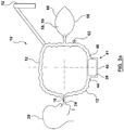
- FIG 1 illustrates an exemplary anesthetic circuit 10 for treating a patient.
- anesthetic circuit 10 comprises a flow passage 12.
- Flow passage 12 provides a passageway for transferring fluid to and from patient 20.
- fluid includes a gas or combination of gases, or a liquid or combination of liquids. Liquids may be present in vapor form, for example. The term fluid may also encompass a mixture of fluids and liquids (which, in some cases, may be in vapor form).
- flow passage 12 provides a hollow conduit.
- Flow passage 12 may be flexible tubing, for example.
- Flow passage 12 may be made of a polymeric material, such as plastic.
- anesthetic circuit 10 may be a ventilation system or, in some cases, operable in conjunction with a ventilation system.
- Anesthetic circuit 10 comprises at least one fluid port 24.
- the at least one fluid port 24 is in fluid communication with flow passage 12 for providing at least external anesthetic agent 16 to patient 20.
- External anesthetic agent 16 will initially anesthetize patient 20, when the anesthetic process commences by delivery of external anesthetic agent 16 to the airway of patient 20, via the at least one fluid port 24.
- the at least one fluid port 24 comprises exit outlet 22 and entry inlet 36. Exit outlet 22 may be configured to be directly received by the airway of patient 20, for delivery of fluid from flow passage 12 to patient 20.
- the at least one fluid port 24 comprises a Y-piece and exit outlet 22 may engage the Y-piece that is received by the airway of patient 20.
- Patient 20 breathes in the external anesthetic agent 16 through his/her airway, thereby delivering the anesthetic agent to the patient's lungs.
- Exhaled fluid mixture 26 comprises exhaled oxygen 28, exhaled carbon dioxide 30 and exhaled anesthetic agent 34.
- Exhaled anesthetic agent 34 may be a molecular anesthetic agent, which may or may not be mixed with other fluids in addition to exhaled oxygen 28 and exhaled carbon dioxide 30.
- molecular anesthetic agents have more than one different atomic element bonded together to form a molecule.
- sevoflurane is a molecular anesthetic agent that has the chemical form (1,1,1,3,3,3-hexafluoro-2-(fluoromethoxy)propane).
- sevoflurane comprises different elements fluorine, carbon and oxygen bonded together.
- noble gases consist of only one atomic element that is not bonded to other atomic elements.
- Exhaled anesthetic agent 34 may originate from external anesthetic agent 16 and may comprise a molecular anesthetic agent.
- exhaled anesthetic agent 34 is a molecular anesthetic agent that was solved in the patient's body (i.e. after cardiac surgery).
- exhaled anesthetic agent 34 comprises a molecular anesthetic agent that was partially solved in the patient's body, and partially contained in external anesthetic agent 16 that was introduced to the patient's airway.
- exhaled molecular anesthetic agent 34 is the only exhaled anesthetic agent. In some embodiments, exhaled anesthetic agent 34 comprises molecular anesthetic agent mixed with other non-molecular anesthetic agents.
- exhaled anesthetic agent 34 comprises a polyhalogenated ether.
- Exhaled anesthetic agent 34 may be hydrophobic (i.e. in gaseous form it dissolves in oil better than water, and in liquid form it is freely miscible with water).
- Non-limiting examples of exhaled anesthetic agent 34 include: sevoflurane, desflurane or isoflurane.
- Exhaled anesthetic agent 34 may be entirely comprised of one of sevoflurane, desflurane or isoflurane, or a mixture thereof.
- Exhaled anesthetic agent 34 may be a volatile anesthetic. Volatile anesthetics are liquid at room temperature (optionally 20°C at 1 atm), but readily evaporate under reduced pressure. Optionally, exhaled anesthetic agent 34 has a vapor pressure at 20°C of between approximately 155 mmHg and 670 mmHg. Optionally, exhaled anesthetic agent 34 has a vapor pressure at 20°C of between approximately 250 mmHg and 500mmHg.
- exhaled anesthetic agent 34 has a boiling point at 760mm in the range of approximately 20°C to 60°C.
- exhaled anesthetic agent 34 is a molecular anesthetic agent that has a molecular weight of at least 150 g/mol.
- exhaled anesthetic agent is a molecular anesthetic agent that has a molecular weight of at least 168 g/mol.
- Xenon which is an atomic anesthetic
- the at least one fluid port 24 may comprise an entry inlet 36 for receiving exhaled fluid mixture 26 from patient 20.
- Flow passage 12 may be in fluid communication with entry inlet 36 for receiving exhaled fluid mixture 26 from entry inlet 36.
- Entry inlet 36 may be configured to be directly received by the airway of patient 20, for delivery of fluid from patient 20 to flow passage 12.
- Entry inlet 36 may be a one-way valve.
- the at least one fluid port 24 may comprise a Y-piece and entry inlet 36 may engage that Y-piece that is received by the airway of patient 20.
- Entry inlet 36 may be separate and distinct from exit outlet 22, as exemplified in Figure 1 . In these cases, exit outlet 22 is configured to receive modified fluid mixture 42 from membrane 38 and provide modified fluid mixture 42 to patient 20.
- anesthetic inlet 14 is separate and distinct from entry inlet 36 and exit outlet 22.
- Exit outlet 22 may be a one-way valve.
- at least one of entry inlet 36 and exit outlet 22 may function as anesthetic inlet 14.
- Anesthetic inlet 14 may be an injector for liquid anesthetic agents.
- anesthetic circuit 10 comprises a membrane 38 that may comprise at least one polymeric material and is in fluid communication with flow passage 12.
- membrane 38 may be contained within a membrane housing 40.
- membrane 38 may fit into an aperture in a wall of flow passage 12, in the absence of membrane housing 40.
- membrane 38 may be fixedly attached to the remainder of a wall of flow passage 12, or formed integrally therewith. In some cases, membrane 38 spans internally between the walls of flow passage 12.
- membrane 38 is configured to receive exhaled fluid mixture 26 from the at least one fluid port 24.
- the at least one fluid port 24 comprises an entry inlet 36 that is separate from exit outlet 22.
- membrane 38 is located downstream from entry inlet 36. In this embodiment, when the exhaled fluid mixture 26 travels through flow passage 12 and after it contacts the membrane 38, a portion of exhaled fluid mixture 26 passes through membrane 38 and out of flow passage 12, to leave a modified fluid mixture 42 in flow passage 12.
- anesthetic circuit 10 comprises a fluid separation apparatus 41, comprising membrane 38 and membrane housing 40.
- Fluid separation apparatus 41 may be releasably connectable to flow path 12.
- fluid separation apparatus 41 is in the form of a cartridge that is releasably connectable to flow path 12.
- fluid separation apparatus 41 may be removed from the anesthetic circuit and replaced with another fluid separation apparatus 41, if the fluid separation becomes damaged, for example.
- Housing inlet 44 may engage flow passage 12 by way for a fluidly sealed friction fit or a clamp coupling, for example.
- a modified fluid mixture 42 is created within membrane housing 40.
- Modified fluid mixture 42 may exit the membrane housing 40 via housing outlet 46.
- Housing outlet 46 may engage flow passage 12 by way for a fluidly sealed friction fit or a clamp coupling, for example. Once the modified fluid mixture 42 exits the membrane housing 40, it may carry on through flow passage 12.
- Membrane 38 may comprise at least one polymeric material. In some embodiments, membrane 38 is entirely made up of polymeric material. In some embodiments, membrane 38 is entirely made up of only one polymeric material. In some embodiments, membrane 38 comprises a polysiloxane and is thereby a polysiloxane membrane. More specifically, membrane 38 may comprise polydimethyl siloxane and thereby be a polydimethyl membrane. In some embodiments, membrane 38 comprises a halocarbon polymer and is thereby a polyhalocarbon membrane. More specifically, membrane 38 may comprise polymethylpentene and thereby be a polymethylpentene membrane.
- the at least one fluid port 24 is configured to receive the modified fluid mixture from membrane 38 and provide at least modified fluid mixture 42 to patient 20.
- exit outlet 22 is configured to receive modified fluid mixture 42 from membrane 38. In some cases, exit outlet 22 is located downstream from membrane 38. Exit outlet 22 provides at least the modified fluid mixture 42 to patient 20. Entry inlet 36 may be located upstream from membrane 38.
- anesthetic circuit 10 comprises a fluid inlet 50 for introducing external fluid from external fluid source 52 to be added to modified fluid mixture 42 in flow passage 12.
- Fluid inlet 50 may be an independent inlet in fluid communication with flow passage 12.
- anesthetic inlet 14 may also serve as fluid inlet 50, as illustrated in Figure 1 .
- Fluid inlet 50 may allow additional fresh fluid (ex. oxygen or air) to be added to flow passage 12 and provided to patient 20 if needed, if the oxygen level within flow passage 12 falls below an acceptable level to support patient 20.
- Oxygen replenishment may be required if, for example, patient 20 increases his/her metabolic rate. Oxygen replenishment may also be required if significant amounts of oxygen exit the flow passage 12 via membrane 38. It should be noted that it is generally cheaper (per unit volume) to add air or oxygen to flow passage 12 than to add external anesthetic agent 16 to flow passage 12.
- External air source 52 may be a tank containing compressed, pressurized fluid (for example, air) therein.
- fluids may at least partially recirculate through flow passage 12.
- An example fluid flow direction 48 is illustrated in Figure 1 .
- membrane 38 may be located in a portion of flow passage 12 that is external to the portion of flow passage 12 that moves fluid in a circular loop corresponding to fluid flow direction 48. In some cases, membrane 38 may be located in a branch passage of flow passage 12 located between fluid source 52 and the portion of flow passage 12 that moves fluid in a circular loop corresponding to fluid flow direction 48. In some embodiments, membrane 38 may be located in anesthetic machine 18.
- Figure 1a illustrates membrane 38 at an alternative location to the location of membrane 38 in Figure 1 .
- anesthetic circuit 10 comprises an external oxygen source 56 for enriching the external fluid with external oxygen.
- External oxygen source 56 may be a tank containing compressed, pressurized oxygen fluid therein.
- the external oxygen may be delivered through fluid inlet 50.
- anesthetic circuit 10 may comprise at least one flow generator 58 for facilitating flow of exhaled fluid mixture 26 and modified fluid mixture 42 through flow passage 12.
- anesthetic machine 18 may serve as flow generator 58, as is commonly known in the art.
- a plurality of flow generators 58 may be provided.
- a first flow generator may drive the flow of the exhaled fluid mixture 26 and a second flow generator may drive the flow of modified fluid mixture 42.
- Examples of flow generator 58 include a motor, fan, pump or vacuum capable of advancing fluids through flow passage 12.
- flow generator 58 comprises compressible member 59.
- compressible member 59 comprises opposing walls 60. When opposing walls 60 are moved towards one another, a positive driving pressure is created in flow passage 12.
- Opposing walls 60 may be flexible.
- Opposing walls 60 may be manually compressible by a human hand.
- the at least one fluid port 24 includes only one fluid port.
- the one fluid port 24 is in fluid communication with flow passage 12 for providing at least external anesthetic agent 16 to patient 20.
- the one fluid port 24 receives the exhaled fluid mixture from patient 20, and flow passage 12 is in fluid communication with the one fluid port 24 to receive exhaled fluid mixture 26 from the one fluid port 24.
- the one fluid port 24 is configured to receive modified fluid mixture 42 from membrane 38 and provide modified fluid mixture 42 to patient 20.
- membrane housing 40 having a membrane therein 38 may also be located between the remainder of flow passage 12 and flow generator 58.
- flow generator 58 may comprise a compressible chamber 59 having opposing walls 60.
- membrane 38 is located in membrane housing 40.
- Exhaled fluid mixture 26 enters membrane housing 40 via housing inlet 44.
- Membrane housing 40 may direct exhaled fluid mixture 26 into contact with membrane 38, to provide modified fluid mixture 42.
- Modified fluid mixture 42 may pass out of membrane housing 40 for a first time via membrane outlet 46.
- Flow generator 58 may direct modified fluid mixture 42 back into membrane housing 40 into contact with membrane 38 for a second time, then membrane housing 40 may direct modified fluid mixture 42 out of membrane housing 40 via housing inlet 44.
- flow generator 58 comprises a bellow comprising a plunger 61 for generating fluid flow.
- anesthetic circuit 10 comprises a membrane housing 40.
- Membrane housing 40 has a membrane housing inlet 44.
- exhaled fluid mixture 26 enters housing 40 at inlet 44 and contacts membrane 38.
- control valve 63 is in an open position. Once the fluid passes membrane 38 when exhalation is completed, control valve 63 closes and fluid is delivered into injection port 67 to force the modified fluid mixture 42 to change direction and flow back towards membrane housing inlet 44 (which now allows modified fluid mixture 42 to exit membrane housing 40).
- modified fluid mixture 42 moves towards membrane housing inlet 44, it passes by membrane 38 for a second time, thereby further reducing the exhaled carbon dioxide 30 concentration in modified fluid mixture 42.
- the forward and reverse fluid flow increases the contact time between the fluid mixture and membrane 38, thereby increasing the efficiency of the exhaled carbon dioxide extraction (per inhalation/exhalation cycle).
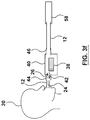
- membrane 38 and membrane housing 40 are located in the vicinity of patient 20's mouth.
- the at least one fluid port 24 includes only one fluid port 24.
- the fluid port provides at least external anesthetic agent 16 to patient 20.
- the fluid port also receives exhaled fluid mixture 26 from patient 20 and directs it toward membrane 38.
- Bellow 60 (or a similar pressure generation device) causes exhaled fluid mixture 26 to pass through membrane 38 twice (in opposite directions), then return to fluid port 24 as modified fluid mixture 42, at which point fluid port 24 receives modified fluid mixture 42 and provides at least modified fluid mixture 42 to patient 20.
- the at least one fluid port 24 comprises only one fluid port 24 and facilitates double fluid flow through membrane 38.
- flow passage 12 is illustrated as a discrete passage that is separate from membrane housing 40 in the figures (see Figures 3f and 3g , for example), it will be appreciated that, in some embodiments, flow passage 12 is not a discrete element and is not separate from membrane housing 40.
- the inside of membrane housing 40 may define the entirety of flow passage 12 and membrane housing 40 (or a small port extending therefrom) may directly engage patient 20's mouth, in the absence of separate flow passage tubing.
- exhaled fluid mixture 26 passes through membrane 38 a first time to become modified fluid mixture 42.
- Modified fluid mixture 42 passes by membrane 38 for a second time, thereby further reducing the exhaled carbon dioxide 30 concentration in modified fluid mixture 42.
- the forward and reverse fluid flow increases the contact time between the fluid mixture and membrane 38, thereby increasing the efficiency of the exhaled carbon dioxide extraction (per inhalation/exhalation cycle).
- anesthetic circuit 10 may also comprise a turbulence-inducing component 64.
- the turbulence-inducing component 64 creates a turbulent flow of exhaled fluid mixture 26 at membrane 38 to increase contact between exhaled fluid mixture 26 and membrane 38.
- Turbulence-inducing component 64 may be any object placed within flow passage 12, as illustrated in Figure 4 , such that the fluids travelling therethrough are forced to flow around the object.
- turbulence-inducing component 64 may comprise a change in geometry within at least one wall of flow passage 12.
- the change in geometry is abrupt, so as to generate fluid flow eddies within flow passage 12.
- the turbulence-inducing component 64 is optionally located upstream and adjacent to the membrane 38. When membrane 38 is contained in membrane housing 40, turbulence-inducing component 64 may be located upstream and adjacent to the housing inlet 44, as illustrated in Figure 4 . Turbulence-inducing component 64 may also be located within membrane housing 40.
- flow passage 12 may have a non-uniform cross-section throughout its length so as to promote turbulent fluid flow through flow passage 12.
- anesthetic circuit 10 may comprise a plurality of membranes 38. Each membrane 38 may be contained within its own membrane housing 40, as exemplified in Figure 5 .
- membrane 38 is at least partially impervious to the exhaled anesthetic agent 34 to at least partially retain exhaled anesthetic agent 34 in flow passage 12 after the exhaled fluid mixture 26 contacts the membrane 38.
- membrane 38 is substantially impervious to the exhaled anesthetic agent 34 to substantially retain exhaled anesthetic agent 34 in flow passage 12 after the exhaled fluid mixture 26 contacts the membrane 38.
- membrane 38 is substantially impervious to exhaled anesthetic agent 34.
- membrane 38 is configured to permeate less than 5% of the anesthetic agent.
- exhaled anesthetic agent 34 may be an exhaled molecular anesthetic agent.
- membrane 38 is substantially impervious to atomic anesthetic agents (i.e. noble gases, including xenon, for example).
- the separation factor of a membrane is defined as the ratio of the permeability of matter A and permeability of matter B.
- the permeability is equal to Flux divided by Partial Pressure Difference.
- the permeability of a membrane to a specific fluid is therefore a property of the membrane, and not directly linked to the operating conditions.
- a membrane's selectivity of fluid A to fluid B is therefore defined as Permeability A divided by Permeability B.
- Membrane 38 may be pervious to exhaled oxygen 28 such that membrane 38 has an exhaled oxygen-to-exhaled anesthetic agent selectivity of greater than 1. In other words, more exhaled oxygen 28 may leave flow passage 12 through membrane 38 than exhaled anesthetic agent 34. Membrane 38 may be pervious to exhaled oxygen 28 such that membrane 38 has an exhaled oxygen-to-exhaled anesthetic agent selectivity of at least two 2. In other words, at least twice as much exhaled oxygen 28 may leave flow passage 12 through membrane 38 than exhaled anesthetic agent 34.
- membrane 38 may be pervious to exhaled oxygen 28 such that is has an exhaled oxygen-to-exhaled anesthetic agent selectivity of at least 3, 4, 5, 10, 50, 100 or 250.
- exhaled anesthetic agent 34 may be an exhaled molecular anesthetic agent.
- membrane 38 is substantially pervious to exhaled oxygen.
- Membrane 38 is pervious to exhaled carbon dioxide such that membrane 38 has an exhaled carbon dioxide-to-exhaled anesthetic agent selectivity of greater than 1. In other words, more exhaled carbon dioxide 30 leaves flow passage 12 through membrane 38 than exhaled anesthetic agent 34. The membrane is more pervious to exhaled carbon dioxide 30 than exhaled anesthetic agent 34 such that the membrane has an exhaled carbon dioxide-to-exhaled anesthetic agent selectivity of greater than 1. Membrane 38 may be substantially pervious to exhaled carbon dioxide such that membrane 38 has an exhaled carbon dioxide-to-exhaled anesthetic agent selectivity of at least 2.
- exhaled carbon dioxide 30 may leave flow passage 12 through membrane 38 than exhaled anesthetic agent 34.
- membrane 38 may be pervious to exhaled carbon dioxide 30 such that is has an exhaled carbon dioxide-to-exhaled anesthetic agent selectivity of at least 3, 4, 5, 10, 50, 100 or 250.
- exhaled anesthetic agent 34 may be an exhaled molecular anesthetic agent.
- membrane 38 is substantially pervious to exhaled carbon dioxide.
- exhaled anesthetic agent 34 which may be an exhaled molecular anesthetic agent
- exhaled oxygen 28 it is advantageous to at least partially (optionally, substantially) retain exhaled anesthetic agent 34, which may be an exhaled molecular anesthetic agent, while allowing some (optionally, a substantial amount of) exhaled oxygen 28 to pass through membrane 38 and out of anesthetic circuit 10.
- Membranes that have these properties provide some advantages over conventional membranes that have a relatively high (carbon dioxide)/(oxygen) selectivity.
- membranes that allow more exhaled oxygen 28 than anesthetic agent 34 (which may be a molecular anesthetic agent) to pass therethrough are advantageous for use in anesthetic circuit 10.
- exhaled anesthetic agent 34 which may be an exhaled molecular anesthetic agent
- exhaled carbon dioxide 30 is permitted to pass through membrane 38 and out of flow passage 12, this prevents the patient from re-inhaling excessive amounts of exhaled carbon dioxide 30, which could have detrimental health effects.
- anesthetic agent 16 (see Figure 1 ) and exhaled anesthetic agent 34, for the purposes of the present application, pertain to substances that are present in sufficient quantities to have (or at least appreciably contribute to) the anesthetic or desired protective effect on patient 20. Therefore, reference to an anesthetic agent refers to chemicals that are added to the naturally occurring constituents of air.
- external anesthetic agent 16 comprises a mixture of different anesthetic agents and exhaled anesthetic agent 34 comprises a mixture of different anesthetic agents.
- exhaled fluid mixture 26 comprises a metabolic product including acetaldehyde, acetone, ethane, ethylene, hydrogen, isoprene, methane, methylamine or pentane.
- Membrane 38 may be pervious to the metabolic product to permeate the metabolic product through membrane 38, and out of flow passage 12.
- membrane 38 has a metabolic product-to-exhaled anesthetic agent 34 (which may be a molecular anesthetic agent) selectivity of greater than 1.
- exhaled fluid mixture 26 contacts membrane 38 to leave modified fluid mixture 42 in the flow passage having a lower amount of the metabolic product than exhaled fluid mixture 26.
- a membrane comprises at least one hollow fiber.
- a membrane comprises a plurality of hollow fibers.
- the membrane may consist entirely of a plurality of hollow fibers.
- the hollow fibers may comprise polymeric material.
- the hollow fibers may consist entirely of polymeric material.
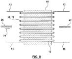
- a membrane comprises a plurality of hollow fibers spaced from one another and adaptable to be substantially parallel to an entry direction of an exhaled fluid mixture when the exhaled fluid mixture initially contacts the plurality of hollow fibers.
- a membrane comprises a plurality of hollow fibers spaced from one another and adaptable to be substantially perpendicular to an entry direction of exhaled fluid mixture when the exhaled fluid mixture initially contacts the plurality of hollow fibers.
- Membrane 38 may be used in an anesthetic circuit, such as anesthetic circuit 10 shown in Figure 1 , for example.
- Figure 9 exemplifies membrane 38 comprising hollow fibers 72 spaced from one another and substantially perpendicular to the entry direction 70 of exhaled fluid mixture 26.
- membrane 38 may be at least partially contained within membrane housing 40.
- hollow fibers 72 are oriented at an angle other than perpendicular or parallel to entry direction 70 of the exhaled fluid mixture.
- Carbon dioxide absorbing material 66 absorbs exhaled carbon dioxide 30 from flow passage 12 and decreases the amount of exhaled carbon dioxide 30 that is re-introduced to patient 20. As exemplified in Figures 10 and 11 , carbon dioxide absorbing material 66 is located on a side of membrane 38 that is external to flow passage 12. Membrane 38 separates carbon dioxide absorbing material 66 from exhaled anesthetic agent 34 (which may be exhaled molecular anesthetic agent) retained in flow passage 12 to impede the exhaled anesthetic agent 34 from contacting the carbon dioxide absorbing material 66.
- exhaled anesthetic agent 34 which may be exhaled molecular anesthetic agent
- membrane 38 selectively allows more exhaled carbon dioxide 30 to pass therethrough than exhaled anesthetic agent 34 (which may be an exhaled molecular anesthetic agent), these harmful reactions are minimized, while still effectively absorbing and extracting the exhaled carbon dioxide 30 out of flow passage 12.
- Figure 12 exemplifies an oxygenator similar in its basic operation to a QUADROX-DTM oxygenator comprising a membrane housing 40 having a blood inlet 76 and a blood outlet 78.
- blood enters membrane housing 40 via blood inlet 76, passes through the membrane in the housing, and exits the membrane housing 40 via blood outlet 78 in a modified form.
- the modified blood exits with a higher oxygen concentration and a lower carbon dioxide concentration.
- blood inlet 76 functions as housing inlet 44.
- exhaled fluid mixture 26 enters membrane housing 40 via housing inlet 44.
- blood outlet 78 functions as housing outlet 46.
- modified fluid mixture 42 exits the membrane housing 40 via housing outlet 46.
- the blood inlet 76 and the blood outlet 78 function as the inlet and outlet for the sweep fluid 84.
- sweep inlet 80 and sweep outlet 82 function as housing inlet 44 and housing outlet 46, respectively.
- the oxygenator similar in its basic operation to QUADROX-DTM has been rotated by 90° relative to the oxygenator exemplified in Figure 12 .
- sweep inlet 80 and sweep outlet 82 engage flow passage 12.
- Exhaled fluid mixture 26 contacts the membrane in Figure 13 ) within the membrane housing 40 such that exhaled fluid mixture 26 is converted to modified fluid mixture 42.
- Tests #5-8 were also conducted in which a QUADROX-DTM oxygenator was used in an anesthetic circuit 10 having one ( Figure 2 ), two, three and four membrane(s) 38 ( Figure 5 ).
- membrane 38 (within the QUADROX-DTM oxygenator) was the OXYPLUSTM membrane.
- an OXYPLUSTM 90/200 membrane having hollow fibers 72 with an outer diameter of 380 micrometers and a dense layer 83 having a thickness of less than 1 micrometer was used.
- membrane housing 40 resembled the configuration described above for Figure 9 .
- the exhaled fluid mixture 26 contacted the outer surface of a hollow fiber 72
- the exhaled oxygen 28 and exhaled carbon dioxide 30 selectively entered the hollow interior of at least one hollow fiber 72.
- the components (or portion thereof) that entered the interior of a hollow fiber 72 then passed through membrane 38 out of the flow passage 12 via at least one end of the hollow fibers 72.
- the portion of the exhaled fluid mixture 26 that remained exterior to the hollow fibers 72 passed around the membrane 38 as modified fluid mixture 42.
- sweep fluid 84 passed through the interior hollow fibers 72 to measure the amount of exhaled oxygen 28, exhaled carbon dioxide 30 and exhaled molecular anesthetic agent 34 in modified fluid mixture 42 that passed into hollow fibers 72.
- concentrations in the exhaled fluid mixture 26 were: 2% exhaled anesthetic agent 34 in oxygen and 4.8% exhaled carbon dioxide 30 in 94% exhaled oxygen 28.
- the flows were 0.8 L/min for sweep fluid 84 (see Figure 13 ) and 2.0 L/min for the exhaled fluid mixture 26.
- the concentrations in the exiting sweep fluid stream were measured using a patient monitor and a quadruple mass spectrometer.
- Figure 19 exemplifies a single hollow fiber 72 of the plurality of hollow fibers 72 shown in Figure 9 , for example.
- Exterior area 116 is separated from the inner lumen 114 of hollow fiber 72 by an outer wall 118.
- Outer wall 118 has a first side 120 that contacts exhaled fluid mixture 26 and permits at least a portion of exhaled carbon dioxide 30 to flow into hollow fiber 72.
- Exterior area 116 may be contained in membrane housing 40 (see membrane housing 40 in Figure 1 , for example).
- Outer wall 118 has a second side 122 that opposes first side 120.
- Modified fluid mixture 42 (with a reduced concetration of exhaled carbon dixoide 30) is provided after at least a portion of exhaled carbon dioxide 30 flows into hollow fiber 72.
- Hollow fiber 72 may permit a sweep fluid 84 to pass therethrough, to facilitate the transport of at least a portion of exhaled carbon dioxide 30 to travel though outer wall 118 into hollow fiber 72. Hollow fibers 72 may direct the exhaled carbon dioxide 30 out of the flow passage 12.
- a sweep fluid 84 may enter the hollow fiber 72 at the sweep inlet 80 and may carry any permeates, like exhaled carbon dioxide 30, out of the hollow fiber 72 via sweep outlet 82.
- membrane 38 is configured such that secondary oxygen in sweep fluid 84 passes through membrane 38 and into flow passage 12.
- Sweep fluid 84 may be substantially pure oxygen or air, for example.
- parameters of the membrane that may be altered include a lower thickness of the membrane, lower density of the membrane, changes in diameter of the hollow fiber, different polymerization of the membrane material resulting in less or more free volume, and/or a more rubbery or more glassy state of the membrane material.
- a shorter length of hollow fibers may limit the accumulation of exhaled carbon dioxide in the sweep fluid inside the hollow fiber and therefore maintain a higher partial pressure gradient for exhaled carbon dioxide and therefore better transport of exhaled carbon dioxide through the membrane.
- planar mat 124 comprises parallel hollow fibers 72 with a spacing 126 between each hollow fiber. In some embodiments, spacing 126 is equal throughout planar mat 124.
- the planar mat shown in Figure 20 comprises warp thread 128 used to space hollow fibers 72 from each other. Warp thread 128 may be woven perpendicular to each hollow fiber 72. Warp thread 128, like hollow fibers 72, may be made of a polymeric material.
- Altering the spacing of the membrane mat layers may introduce a more even flow pattern and evenly distributed carbon dioxide concentration and may, therefore, increase the average exhaled carbon dioxide transport from the exhaled fluid mixture through the membrane.
- membrane 38 may comprise planar mat 124, or a series of planar mats 124, stacked with each other.
- the hollow fibers 72 of each stacked planar mat 124 may be aligned to provide a plurality of parallal or perpendicular hollow fibers 72, as shown in Figures 8 and 9 , respectively.
- planar mats 124 may be stacked such that the orientations of the hollow fibers vary from one planar mat relative to another.
- hollow fibers 72 may be formed in a planar mat 124 wherein the hollow fibers in the same planar mat 124 are arranged at different angles to one another. In some embodiments, at least some of hollow fibers 72 in a planar mat 124 are arranged so that they are not parallel or perpendicular to entry direction 70 of exhaled fluid mixture 26 (see Figures 8 and 9 for entry direction 70). In some embodiments, all of hollow fibers 72 are arranged at an angle other than 0° or 90° relative to entry direction 70.
- a membrane 38 in another embodiment of this disclosure, comprises a plurality of hollow fibers 72 wound into a cylindrical roll 130 defining a hollow inner core 134 having an open end 150 to receive exhaled fluid mixture 26 therein.
- Cylindrical roll 130 may have a closed end 152, comprising a snap-fit cap or plug, for example.
- membrane 38 is configured to direct exhaled fluid mixture 26 radially outwardly from hollow inner core 134. As exhaled fluid mixture 26 travels radially outwardly, it contacts the plurality of hollow fibers 72 of membrane 38, to thereby convert exhaled fluid mixture 26 to modified fluid mixture 42.
- Figure 21b illustrates a cut-away view along line A-A in Figure 21a .
- Figures 21a and 21b illustrate cylindrical roll 130 as a solid body for ease of illustration, it will be appreciated that the cylindrical roll 130 exemplified in Figures 21a and 21b is made up of a plurality of hollow fibers 72.
- relatively long hollow fibers are wrapped or spun around a spool (in a "yarn-like" manner, for example), and cross-wound with one another.
- a plurality of hollow fibers may be randomly arranged into a cylindrical roll 130.
- a membrane in another embodiment of this disclosure, comprises a first planar mat rolled together in a cylindrical roll forming concentric layers of substantially parallel hollow fibers. Conversely, if the hollow fibers in the planar mat are angularly oriented to one another, the concentric layers of the hollow fibers are randomly arranged relative to one another.
- rolled first planar mat defines a hollow inner core having a first open end to receive exhaled fluid and a closed second end.
- Membrane 38 may comprise a rolled planar mat 124.
- Figures 21 and 22 exemplify single hollow fibers 72 or hollow fiber mats 124 (see Figure 20 ) arranged as a cylindrical roll 130 with the hollow fibers 72 having a spacing between the fibers 126 and a layer spacing 132.
- the plurality of hollow fibers 72 in planar mat 124 may be spaced from and substantially parallel with one another.
- the planar mat 124 may be rolled together in a cylindrical roll 130 forming concentric layers of substantially parallel hollow fibers 72.
- hollow fibers 72 may be angled relative to one another.
- planar mat 124 defines a hollow inner core 134 along the longitudinal axis of cylindrical roll 130.
- exhaled fluid mixture 26 flows radially outwardly through wall thickness 136 to provide modified fluid mixture 42.
- a membrane has a portion of the plurality of hollow fibers formed in a second planar mat.
- the plurality of hollow fibers in the second planar mat are spaced from and substantially parallel with one another.
- the first planar mat is overlapped with the second planar mat.
- the plurality of hollow fibers are formed in a first planar mat and a second planar mat.
- the overlapped first and second planar mats are rolled together in a cylindrical roll forming concentric layers of the hollow fibers.
- the first planar mat is overlapped with the second planar mat so that the hollow fibers of the first planar mat are oriented at an angle to the hollow fibers of the second planar mat to provide concentric layers of cross wound hollow fibers.
- the rolled first planar mat and second planar mat may define a hollow inner core having a first open end configured to receive the exhaled fluid mixture and a closed second end.
- Membrane 38 may comprise a plurality of planar mats which overlap one another to form cross wound hollow fibers 72.
- the plurality of hollow fibers 72 may be formed in first planar mat 124 and second planar mat 140.
- a first planar mat 124 (as shown in Figure 19 )
- a second planar mat 140 which is similar to planar mat 124, is rolled onto temporary bobbin 142.
- the plurality of hollow fibers 72 in the first planar mat 124 are spaced from and substantially parallel with each other.
- the plurality of hollow fibers 72 is second planar mat 140 are spaced from and substantially parallel with each other.
- the spacing 126 between all hollow fibers 72 in the same planar mat is substantially the same.
- Each of the first planar mat 124 and second planar mat 140 are unwound from their respective temporary bobbins 138 and 142 and each pulled into trapezoidal shapes defined between hollow fibers 72 and warp thread 128 to overlap the first planar mat 124 and the second planar mat 140 with one another as they are unwound (see Figure 24 ).
- the first planar mat 124 may be overlapped with the second planar mat 140 so that the hollow fibers 72 of first planar mat 124 are oriented at an angle 144 to hollow fibers 72 of second planar mat 140.
- a cross wound roll 146 is formed, and may be rolled onto temporary bobbin 148 for transport or storage. Once temporarily bobbin 148 is removed, a hollow inner core 134 (in the form of a void) is provided in cross wound roll 146. In turn, cross wound roll 146 is provided which may be used as membrane 38.
- angle 144 in Figure 24 may be zero, in which case all of the hollow fibers 72 of first planar mat 124 and second planar mat 140 are substantially parallel to one another.
- membrane 38 comprises multiple rolled planar mats, but otherwise appears similar to cylindrical roll 130 shown in Figures 21 and 22 .
- Figure 26 exemplifies flow separation apparatus 41 comprising membrane 38 in the form of cylindrical roll 130 of Figures 21 and 22 or cross wound roll 146 of Figure 25 within exemplary membrane housing 40.
- flow separation apparatus 41 is releasably connectable to an anesthetic circuit.
- fluid separation apparatus 41 is in the form of a cartridge that is releasably connectable to flow path 12.
- membrane housing 40 has housing inlet 44 and housing outlet 46 located concentrically relative to one another. The exhaled fluid mixture 26 enters housing 40 through housing inlet 44.
- hollow inner core 134 of roll 130 or 146 has a first open end 150 configured to receive exhaled fluid mixture 26, and a closed second end 152.
- exhaled fluid mixture 26 contacts outer wall 118 of at least some of hollow fibers 72 (see Figure 19 for an example hollow fiber 72).
- exhaled carbon dioxide 30 is extracted from exhaled fluid mixture 26 into hollow fibers 72.
- Sweep fluid 84 enters membrane housing 40 through sweep inlet 80. At the same time that exhaled fluid mixture 26 passes along the outer surfaces of hollow fibers 72, sweep fluid 84 passes through the inner lumen 114 (see Figure 19 ) of hollow fibers 72, thereby extracting exhaled carbon dioxide 30 from exhaled fluid mixture 26. Sweep fluid 84, enriched with exhaled carbon dioxide 30, then exits membrane housing 40 via sweep outlet 82.
- exhaled fluid enters membrane housing 40 as exhaled fluid mixture 26 during patient inhalation, and exits membrane housing 40 as modified fluid mixture 42 via the same membrane housing inlet 44.
- membrane housing inlet 44 and membrane housing outlet 46 are separate and concentric with one another.
- Exhaled fluid mixture 26 entered the housing as a fluid comprising 93% oxygen, 4.8% carbon dioxide and 2.2% other partitions that leaked in from the air.
- Sweep fluid 84 entered the housing as 100% oxygen.
- Exhaled fluid mixture 26 contacted hollow fibers 72 to extract exhaled carbon dioxide 30 from exhaled fluid mixture 26 to form modified fluid mixture 42.
- the data shows that modified fluid mixture 42 had a lower percentage of carbon dioxide than exhaled fluid mixture 26.
- Exhaled fluid mixture 26 passed around the exterior of the hollow fibers from hollow inner core 134 to an opposing, exterior side of hollow fibers 72 (i.e. membrane 38) to form modified fluid mixture 42.
- the extraction process was dependent on the flow rate (measured in liters per minute) of exhaled fluid mixture 26 when it contacted hollow fibers 72 and of sweep fluid 84 flowing though the inside of hollow fibers 72.
- Table 6 shows the relative concentration percentages (by volume) of carbon dioxide and oxygen in sweep fluid 84 after exhaled fluid mixture 26 was treated by membrane 38. As shown in Table 6, when exhaled fluid mixture 26 flowed around the exterior of hollow fibers 72, at least some of exhaled carbon dioxide 30 in exhaled fluid mixture 26 flowed into hollow fibers 72 and out of flow passage 12 (i.e. out of the modified fluid mixture 42 that flowed around hollow fibers 72).
- Tables 5 and 6 show that hollow fibers 72 extracted exhaled carbon dioxide 30 from exhaled fluid mixture 26, to form modified fluid mixture 42.
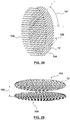
- a membrane comprises a plurality of hollow fibers formed in planar discs vertically stacked upon one another.
- the hollow fibers in each planar disc may be spaced from one another and oriented substantially parallel to one another in a corresponding disc direction.
- the corresponding disc direction for a first disc is different than the corresponding disc direction for any other disc stacked directly adjacent to the first disc.
- the corresponding disc direction for all of the stacked discs may be substantially the same.
- membrane 38 comprises a plurality of hollow fibers 72 formed in planar discs 154 stacked upon one another.
- the planar discs may be cut from planar mats similar to the planar mat discussed with reference to Figure 20 . As illustrated in Figures 28 and 29 , each planar mat may be cut to define a mat having a rounded perimeter.
- planar discs 154 have a circular shape. In other embodiments, planar discs 154 have an elliptical shape.
- Planar discs 154 may be stacked with a defined vertical disc spacing distance 156 between each disk. In some embodiments, vertical spacing distance 156 is zero, and the stacked planar discs 154 are in direct contact with one another. In some cases, the spacing 126 between all hollow fibers 72 in the same planar disc 154 is equal.
- hollow fibers 72 in each planar disc are spaced from one another and oriented substantially parallel to one another in a corresponding disc direction.
- the corresponding direction of a first of planar discs 154 is different than the corresponding disc direction for any other planar disc directly adjacent to the first of planar discs 154.
- the corresponding disc directions for all of the stacked planar discs 154 may be substantially the same, in which case all of the hollow fibers 72 are substantially in parallel.
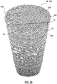
- Hollow fiber discs 154 may be stacked to result in a membrane 38 in the form of stacked cylinder 158, as shown in Figure 30 .
- stacked cylinder 158 contains approximately 175 to 225 planar disks 154.
- Each planar disk 154 may be glued to any planar disc directly above or below it.
- the glue may be placed on each planar disc 154 in a radial manner, so as to define a gas impermeable glue line 160 that defines a cylindrical channel 162 located radially inwardly of glue line 160. Cylindrical channel 162 may be configured to receive exhaled fluid mixture 26.
- FIG 31 illustrates an example membrane housing 40 for housing stacked cylinder 158, as discussed above with reference to Figure 30 .
- Stacked cylinder 158 may be glued to either end cap of the housing 40 via glue line 160 to form a fluid separation apparatus 41.
- membrane housing 40 has sweep inlet 80, sweep outlet 82, membrane housing inlet 44 and a membrane housing outlet 46.
- the space between the outer wall of membrane housing 40 and stacked cylinder 158 may be divided into two symmetrical compartments by two baffles 164. Sweep inlet 80 and sweep inlet 82 may be each located in a respective one of the two symmetrical volumes created by baffles 164.
- membrane outlet 46 is at the same end of membrane housing 40 as sweep inlet 80 and sweep outlet 82, between the sweep inlet and sweep outlet.
- Figure 32 shows a cut-away view through fluid separation apparatus 41 comprising a membrane housing 40.
- fluid separation apparatus 41 is releasably connectable to an anesthetic circuit.
- fluid separation apparatus 41 is in the form of a cartridge that is releasably connectable to flow path 12.
- Exhaled fluid mixture 26 enters membrane housing 40 via membrane housing inlet 44.
- the resulting modified fluid mixture 42 that flows past at least some of hollow fibers 72 has a reduced concentration of exhaled carbon dioxide 30.
- Figure 32 exemplifies housing outlet 46 at the same end of membrane housing 40 as membrane housing inlet 44.
- Sweep fluid 84 enters membrane housing 40 through sweep inlet 80.
- exhaled fluid mixture 26 passes though cylindrical channel 162 of stacked cylinder 158 and around at least some of hollow fibers 72 of stacked cylinder 158, exhaled carbon dioxide 30 is transported through outer wall 118 (see Figure 19 ) of hollow fibers 72, and out of flow passage 12 via hollow fibers 72.
- Sweep fluid 84, enriched with exhaled carbon dioxide 30, then exits membrane housing 40 via sweep outlet 82.
- a membrane exemplified in Figure 33 , is located in an elongate channel having a longitudinal centerline.
- the elongate channel is elongated about the longitudinal centerline.
- the plurality of hollow fibers are arranged substantially perpendicular to the longitudinal centerline of the channel.
- the elongate channel has a rounded cross-section in a plane perpendicular to the longitudinal centerline.
- the elongate channel has a cross-section in a plane perpendicular to the longitudinal centerline and having a cross-sectional area of approximately 300 mm 2 to 20,000 mm 2 .
- the longitudinal centerline may be curved.
- FIG. 33 exemplifies a membrane that may be used as membrane 38.
- the plurality of hollow fibers 72 of membrane 38 is located in membrane housing 40 to form a fluid separation apparatus 41.
- Membrane housing 40 is an elongate channel 166 having a longitudinal centerline 168.
- Elongate channel 166 is elongated about longitudinal centerline 168.
- the plurality of hollow fibers 72 may be arranged substantially perpendicular to longitudinal centerline 168.
- hollow fibers 72 may be oriented at an angle other than 90° or 0° relative to longitudinal centerline 168. In these cases, exhaled fluid mixture 26 flows around hollow fibers 72, to remove exhaled carbon dioxide 30 from exhaled fluid mixture 26.
- elongate channel 166 may have a substantially rectangular cross-section in a plane perpendicular to the longitudinal centerline 168.
- elongate channel 166 may have a rounded cross-section in a plane perpendicular to longitudinal centerline 168.
- elongate channel 166 may have a circular, oval, or elliptical cross-section. In other cases, elongate channel 166 may have curved edges.
- Elongate channel 166 may have a cross-sectional area (in a plane perpendicular to longitudinal centerline 168) of approximately 300 mm 2 to 20,000 mm 2 .
- Figures 33 , 34 and 35 show housing inlet 44 and housing outlet 46 at opposite ends of elongate channel 166.
- exhaled fluid mixture 26/modified fluid mixture 42 flow once past membrane 38.
- housing inlet 44 and housing outlet 46 are located at the same end of elongated channel 166, to facilitate bi-directional (double) fluid flow across hollow fibers 72 of membrane 38.
- elongate channel 166 has a curved longitudinal centerline 168.
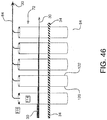
- Figure 36 exemplifies a fluid separation apparatus 41 comprising a continuous elongate channel 166 disposed in membrane housing 40 and arranged in a spiral pattern.
- membrane housing 40 has a membrane housing inlet 44.
- exhaled fluid mixture 26 enters housing 40 at membrane housing inlet 44 and travels in a direction parallel to longitudinal centerline 168 of channel 166.
- exhaled fluid mixture 26 passes over hollow fibers 72 (shown in Figures 34 and 35 )
- exhaled carbon dioxide 30 is extracted to provide modified fluid mixture 42.
- valve 170 is in an open position.
- valve 170 closes and external fluid enters elongate channel 166 via injection port 172 (which may be near valve 170) to force the modified fluid mixture 42 to change direction and flow back towards membrane housing inlet 44 (which now functions to allow modified fluid mixture 42 to exit membrane housing 40).
- injection port 172 which may be near valve 170
- modified fluid mixture 42 moves towards membrane housing inlet 44 after it passes by hollow fibers 72 for a second time, it further reduces the exhaled carbon dioxide concentration in modified fluid mixture 42.
- the forward and reverse fluid flow increases the contact time between the fluid mixture and the hollow fiber membranes, thereby increasing the efficiency of the exhaled carbon dioxide extraction (per inhalation/exhalation cycle).
- the elongate channel 116 in conjunction with injection port 172, may act as the flow generator to promote fluid movement through elongate channel 116 and, in some cases through other portions of flow passage 12 (see flow passage 12 in Figure 1 , for example).
- a membrane exemplified in Figure 37 , is located in a housing and at least one hollow fiber of the membrane has a corresponding shape and orientation that is different than the corresponding shape and orientation of another hollow fiber.
- each hollow fiber has a corresponding shape and orientation that is different than a corresponding shape and orientation of all other hollow fibers in the housing.
- Figure 37 illustrates a further embodiment for fluid separation apparatus 41 comprising membrane 38 and membrane housing 40, wherein membrane 38 comprises a plurality of hollow fibers 72 in membrane housing 40.
- membrane 38 comprises a plurality of hollow fibers 72 in membrane housing 40.
- at least one hollow fiber 72 has a corresponding shape and orientation that is different than a corresponding shape and orientation of another hollow fiber.
- each hollow fiber has a corresponding shape and orientation that is different than a corresponding shape and orientation of all other hollow fibers in membrane housing 40.
- Each hollow fiber 72 may have a curved shape and angular orientation relative to membrane housing 40 that is different than the curved shape and angular orientation of all other hollow fibers 72 in the membrane housing 40.
- hollow membranes 72 may be randomly packed (randomly oriented) into membrane housing 40 in a "spaghetti noodle-like" manner.
- the amount of hollow fibers 72 used per volume of space within membrane housing 40 defines the resistance for the exhaled fluid mixture 26 passing through from membrane housing inlet 44 to membrane housing outlet 46.
- a sweep fluid 84 travels through inner lumen 114 in hollow fibers 72 (see Figure 19 ) to facilitate the removal of exhaled carbon dioxide from exhaled fluid mixture 26 introduced into membrane housing 40.
- Each of the embodiments of membrane 38 described above may be located in a membrane housing 40 within an anesthetic circuit 10 having a membrane housing inlet 44 and a membrane housing outlet 46.
- exhaled anesthetic fluid 26 enters membrane housing 40 via membrane housing inlet 44, flows once through membrane 38, then exits membrane housing 40 via membrane housing outlet 46 as modified fluid mixture 42.
- Figures 26 and 32 show membrane housing inlet 44 and membrane housing outlet 46 located at the same end of the membrane housing 40.
- Figures 26 and 32 are applicable to anesthetic circuits 10 similar to those illustrated in Figures 1 , 2 , 3a , 4 , 5 , 6 and 7 , for example, when slightly modified.
- Figure 38 illustrates the anesthetic circuit of Figure 1 , slightly modified to have housing outlet inlet 44 and housing outlet 46 on the same side of membrane housing 40.
- Anesthetic circuit 10, as shown in Figure 1 for example has exit outlet 22 and entry inlet 36.
- entry inlet 36 and exit outlet 22 may be different openings in flow passage 12.
- a further disclosure not claimed comprises a method for anesthetic treatment of a patient.
- the method comprises introducing an external anesthetic agent 16 towards and into a patient via flow passage 12.
- External anesthetic agent 16 may be stored in anesthetic machine 18 or another external source. This anesthetic agent is delivered to patient 20, through flow passage 12.
- the external anesthetic agent 16 travels to the patient's lungs.
- the patient's lungs produce an exhaled fluid mixture 26, which is expelled from the airway of patient 20 as he/she exhales. Exhaled fluid mixture 26 is then directed away from and out of patient 20 into flow passage 12.
- Exhaled fluid mixture 26 from the patient 20 comprises exhaled oxygen 28, exhaled carbon dioxide 30 and exhaled anesthetic agent 34.
- Exhaled fluid mixture 26 is advanced through flow passage 12 towards and into contact with membrane 38 comprising a plurality of hollow fibers in fluid communication with the flow passage. More of exhaled carbon dioxide 30 than exhaled anesthetic agent 34 is transferred out of the flow passage after exhaled fluid mixture 26 contacts membrane 38 to leave modified fluid mixture 42 in flow passage 12.
- Modified fluid mixture 42 has a lower concentration of exhaled carbon dioxide 30 than exhaled fluid mixture 26.
- Modified fluid mixture 42 is advanced through flow passage 12 toward patient 20 to provide at least modified fluid mixture 42 to patient 20.
- Exhaled anesthetic agent 34 may be an exhaled molecular anesthetic agent.
- Fluid separation apparatus 41 is fluidly connectable to an anesthetic circuit (such as anesthetic circuit 10 shown in Figure 1 , for example).
- anesthetic circuit 10 has flow passage 12 for transporting exhaled fluid mixture 26 containing at least exhaled anesthetic agent 34 and exhaled carbon dioxide 30 through flow passage 12.
- fluid separation apparatus 41 is releasably connectable with flow passage 12 of anesthetic circuit 10.
- fluid separation apparatus 41 is a cartridge releasably connectable with flow passage 12 of anesthetic circuit 10.
- fluid separation apparatus 41 is configured to receive exhaled fluid mixture 26 via housing inlet 44.
- exhaled fluid mixture 26 may flow into hollow inner core 134.
- the fluid pressure in inner core 134 is increased as flow continues.
- Closed second end 152 facilitates this increase in pressure, since exhaled fluid mixture 26 cannot escape hollow inner core 134 via closed second end 152.
- Closed second end 152 may be a plug or snug-fit cap, for example.
- closed second end 152 may be integrally formed in membrane housing 40.
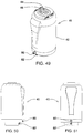
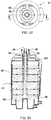
- Figure 52 shows a top view of fluid separation apparatus 41 of Figures 49 to 51 .
- Figure 53 shows a cut-away side view along line A-A in Figure 52.
- Figure 53 shows the flow of exhaled fluid mixture 26 from membrane housing inlet 44, through membrane 38; and modified fluid mixture 42 out of membrane housing outlet 46 in a similar manner to that illustrated for the fluid separation apparatus of Figure 44 .
- exhaled fluid mixture 26 / modified fluid mixture 42 may flow in the opposite direction to that shown in Figure 53 .
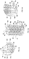
- FIG 54 exemplifies a flow path of sweep fluid 84 through the fluid separation apparatus of Figures 49 to 53 .
- Membrane housing 40 is configured to direct sweep gas 84 received from sweep inlet 80 through a first portion 176 of the plurality of hollow fibers 72 in a first sweep direction and subsequently through a second portion 178 of the plurality of hollow fibers 72 in a second sweep direction substantially opposite to the first sweep direction before sweep gas 84 exits membrane housing 40 via sweep outlet 82.
- first portion 176 of the plurality of hollow fibers 72 is radially outward of second portion 178 of the plurality of hollow fibers 72.
- sweep fluid 84 may enter membrane housing 40 via sweep inlet 80.
- Dividing wall 180 may be configured to direct sweep fluid 84 through membrane 38.
- sweep fluid 84 By recirculating sweep fluid 84 through membrane 38, less sweep fluid is required to run the system. This can result in cost and energy savings.
- the recirculation also makes the extraction of exhaled carbon dioxide from exhaled fluid mixture more efficient.
- the partial pressure and concentration of carbon dioxide in sweep fluid 84 has to be lower than in exhaled fluid mixture 26.
- sweep flow 84 flows through a smaller number of hollow fibers 72 in a first portion 176 of the plurality of hollow fibers 72 than it does as it flows in a subsequent direction through the second portion 178 of hollow fibers 72.
- Figure 54 illustrates a double-flow of sweep fluid through membrane 38
- sweep fluid 84 may flow through membrane 38 more than twice.
- a concentration difference of carbon dioxide is also maintained, in the manner described above, such that sweep fluid 84 has the lowest concentration of carbon dioxide as it flows through a first portion 176 of hollow fibers 72 and then has a higher concentration of carbon dioxide as it flows through subsequent portions of hollows fibers 72.
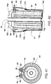
- Figure 61 shows a top view of fluid separation apparatus 41 of Figures 57 to 59 , showing the flow of sweep fluid 84 through fluid separation apparatus 41.
- the flow path of sweep fluid 84 is also illustrated in Figure 62 , which shows a cut-away side view along line B-B in Figure 59 .
- the flow path is substantially the same as that shown in Figure 54 except that sweep gas 84 is received from sweep inlet 80 at an opposing end of membrane housing 40 (as compared to Figure 54 ).
- sweep gas 84 flows through a first portion 176 of the plurality of hollow fibers 72 and subsequently through a second portion 178 of the plurality of hollow fibers 72 in substantially opposite directions to those shown in Figure 54 .
- inner shaft 174 has a first end 186 and a second end 187.
- first end 186 may be located in membrane housing 40 with first end 186 closer to membrane housing inlet 44 than second end 187. Studies showed that this arrangement facilitated more even flow distribution of exhaled fluid mixture 26 into membrane 38 than an arrangement wherein inner shaft 174 has apertures 175 of equal size.
- Tables 7 and 9 show the inspired fraction (Fi [Vol%]) of oxygen, CO 2 , sevoflurane (FiO 2 , FiCO 2 , FiSevo) at the absorber outlet, and the end tidal fraction (et [Vol%]) of oxygen, CO 2 , sevoflurane (etO 2 , etCO 2 , etSevo) in the exhaled fluid mixture.
Landscapes
- Health & Medical Sciences (AREA)
- Engineering & Computer Science (AREA)
- Chemical & Material Sciences (AREA)
- Biomedical Technology (AREA)
- Anesthesiology (AREA)
- Life Sciences & Earth Sciences (AREA)
- Environmental & Geological Engineering (AREA)
- Pulmonology (AREA)
- Veterinary Medicine (AREA)
- Animal Behavior & Ethology (AREA)
- General Health & Medical Sciences (AREA)
- Public Health (AREA)
- Hematology (AREA)
- Heart & Thoracic Surgery (AREA)
- Emergency Medicine (AREA)
- Analytical Chemistry (AREA)
- General Chemical & Material Sciences (AREA)
- Oil, Petroleum & Natural Gas (AREA)
- Chemical Kinetics & Catalysis (AREA)
- Biodiversity & Conservation Biology (AREA)
- Ecology (AREA)
- Environmental Sciences (AREA)
- Separation Using Semi-Permeable Membranes (AREA)
- External Artificial Organs (AREA)
Claims (16)
- Appareil de séparation de fluides (41) pouvant être raccordé de manière fluidique à un circuit anesthésique (10), le circuit anesthésique (10) ayant un passage d'écoulement (12) pour transporter un mélange de fluides exhalés (26) contenant au moins un agent anesthésique exhalé (34) et du dioxyde de carbone exhalé (30) à travers le passage d'écoulement (12), l'appareil de séparation de fluides (41) comprend :une membrane (38) ayant une pluralité de fibres creuses (72), dans lequella membrane (38) est au moins partiellement imperméable à l'agent anesthésique exhalé (34) pour conserver au moins partiellement l'agent anesthésique exhalé (34) dans le passage d'écoulement (12) après que le mélange de fluides exhalés (26) est entré en contact avec la membrane (38), etla membrane (38) est plus perméable au dioxyde de carbone exhalé (30) qu'à l'agent anesthésique exhalé (34) de sorte que la membrane (38) a une sélectivité dioxyde de carbone exhalé-agent anesthésique exhalé supérieure à 1 ; etla membrane est inerte par rapport au dioxyde de carbone exhalé et est exempte d'acides aminés ; etun logement de membrane (40) contenant la membrane (38) à l'intérieur de celui-ci, dans lequelle logement (40) est configuré pour recevoir le mélange de fluides exhalés (26) via une entrée de logement (44),le logement de membrane (40) dirige le mélange de fluides exhalés (26) pour le mettre en contact avec la membrane (38), pour fournir un mélange de fluides modifié (42) ayant une quantité plus faible du dioxyde de carbone exhalé (30) que le mélange de fluides exhalés (26),le logement de membrane (40) dirige le mélange de fluides modifié (42) hors du logement de membrane (40) via une sortie de logement (46),au moins l'une de la pluralité de fibres creuses (72) permet à un fluide de balayage (84) de passer à travers celles-ci pour faciliter le transport d'au moins une partie du dioxyde de carbone exhalé (30) dans l'au moins une fibre creuse (72), etle logement de membrane (40) a au moins une entrée de balayage (80) pour recevoir le fluide de balayage (84) à travers celle-ci et au moins une sortie de balayage (82) pour rejeter le fluide de balayage (84) hors du logement de membrane (40).
- Appareil de séparation de fluides (41) selon la revendication 1, dans lequel la pluralité de fibres creuses (72) sont enroulées pour former un rouleau cylindrique (130) définissant une âme interne creuse (134) ayant une extrémité ouverte (150) pour recevoir le mélange de fluides exhalés (26).
- Appareil de séparation de fluides (41) selon la revendication 1 ou 2, dans lequel
le logement de membrane (40) est configuré pour diriger le gaz de balayage (84) reçu en provenance de l'entrée de balayage (80) à travers une première partie de la pluralité de fibres creuses (72) dans une première direction de balayage et ensuite à travers une seconde partie de la pluralité de fibres creuses (72) dans une seconde direction de balayage sensiblement à l'opposé de la première direction de balayage avant que le gaz de balayage (84) quitte le logement (40) via la sortie de balayage (82), et
la première partie de la pluralité de fibres creuses (72) est radialement à l'extérieur de la seconde partie de la pluralité de fibres creuses (72). - Appareil de séparation de fluides (41) selon l'une quelconque des revendications 1 à 3, dans lequel
le fluide de balayage (84) comprend au moins un gaz à l'azote, la membrane (38) est au moins partiellement imperméable au gaz à l'azote et perméable au fluide de dioxyde de carbone exhalé (30) de sorte que la membrane (38) a une sélectivité dioxyde de carbone exhalé-gaz à l'azote supérieure à 1. - Appareil de séparation de fluides (41) selon la revendication 2, dans lequel
le logement de membrane (40) comprend un axe interne (174) inséré dans l'âme interne creuse (134) de la membrane (38),
l'axe interne (174) a une pluralité d'ouvertures (175) à l'intérieur de celui-ci pour diriger le mélange de fluides exhalés (26) à travers les ouvertures (175) et dans la membrane (38), et
les ouvertures (175) situées plus loin de l'entrée de logement de membrane (44) sont globalement plus petites que les ouvertures (175) situées plus près de l'entrée de logement de membrane (44). - Circuit anesthésique (10) pour traiter un patient, comprenant un passage d'écoulement (12) pour transporter un mélange de fluides exhalés (26) contenant au moins un agent anesthésique exhalé (34) et du dioxyde de carbone exhalé (30) à travers le passage d'écoulement (12) raccordé de manière fluidique à un appareil de séparation de fluides selon les revendications 1 à 5.
- Circuit anesthésique (10) selon la revendication 6, comprenant
une entrée d'agent anesthésique (14) en communication fluidique avec le passage d'écoulement (12) pour introduire un agent anesthésique externe (16) dans le passage d'écoulement (12) ;
au moins un orifice pour fluides (24) en communication fluidique avec le passage d'écoulement (12) pour fournir au moins l'agent anesthésique externe (16) au patient (20), dans lequel
l'au moins un orifice pour fluides (24) reçoit le mélange de fluides exhalés (26) en provenance du patient (20), le mélange de fluides exhalés (26) comprenant un oxygène exhalé (28), le dioxyde de carbone exhalé (30) et l'agent anesthésique exhalé (34), le passage d'écoulement (12) étant en communication fluidique avec l'au moins un orifice pour fluides (24) pour recevoir le mélange de fluides exhalés (26) en provenance de l'au moins un orifice pour fluides (24) ;
dans lequel la membrane est configurée pour recevoir le mélange de fluides exhalés (26) en provenance de l'au moins un orifice pour fluides (24), dans lequel
l'au moins un orifice pour fluides (24) est configuré pour recevoir le mélange de fluides modifiés (42) en provenance de la membrane (38) et fournir au moins le mélange de fluides modifié (42) au patient (20) ; et
une entrée de fluide (50) pour introduire un fluide externe dans le passage d'écoulement (12) à ajouter au mélange de fluides modifié (42) fourni au patient (20) ;
caractérisé en ce que :chaque fibre creuse (72) a une surface externe qui entre en contact avec le mélange de fluides exhalés (26) et permet à au moins une partie du dioxyde de carbone exhalé (30) de s'écouler dans la fibre creuse (72), etles fibres creuses (72) dirigent le fluide de balayage (84) et le dioxyde de carbone exhalé (30) hors du passage d'écoulement (12). - Circuit anesthésique (10) selon la revendication 7, dans lequel
l'agent anesthésique exhalé (16) est un agent anesthésique moléculaire exhalé (34) ;
la membrane (38) comprend au moins un matériau polymérique ;
la membrane (38) est perméable à l'oxygène exhalé (28) de sorte que la membrane (38) a une sélectivité oxygène exhalé-agent anesthésique moléculaire exhalé supérieure à 1. - Circuit anesthésique (10) selon l'une quelconque des revendications 7 à 8, dans lequel un matériau absorbant le dioxyde de carbone (66) est situé sur un côté de la membrane (38) qui est externe au passage de fluide (12), dans lequel la membrane (38) sépare le matériau absorbant le dioxyde de carbone (66) en provenance de l'agent anesthésique exhalé (34) conservé dans le passage d'écoulement (12) pour empêcher l'agent anesthésique exhalé (34) d'entrer en contact avec le matériau absorbant le dioxyde de carbone (66).
- Circuit anesthésique (10) selon l'une quelconque des revendications 7 à 9, dans lequel
le mélange de fluides exhalés (26) comprend un produit métabolique incluant de l'acétaldéhyde, de l'acétone, de l'éthane, de l'éthylène, de l'hydrogène, de l'isoprène, du méthane, de la méthylamine ou du pentane ;
la membrane (38) est perméable au produit métabolique ; et
le mélange de fluides exhalés (26) entre en contact avec la membrane (38) pour laisser un mélange de fluides modifié (42) dans le passage d'écoulement (12) ayant une quantité plus faible du produit métabolique que le mélange de fluides exhalés (26). - Circuit anesthésique (10) selon l'une quelconque des revendications 7 à 10, dans lequel l'au moins un orifice pour fluides (24) comprend :une sortie (22) en communication fluidique avec le passage d'écoulement (12) pour fournir au moins l'agent anesthésique externe (16) au patient (20) ; etune entrée (36) distincte de la sortie (22) pour recevoir le mélange de fluides exhalés (26) en provenance du patient (20), le passage d'écoulement (12) étant en communication fluidique avec l'entrée (36) pour recevoir le mélange de fluides exhalés (26) en provenance de l'entrée (36), et dans lequella sortie (22) est configurée pour recevoir le mélange de fluides modifié (42) en provenance de la membrane (38) et fournir le mélange de fluides modifié (42) au patient (20).
- Circuit anesthésique (10) selon l'une quelconque des revendications 7 à 11, dans lequel
l'au moins un orifice pour fluides (24) inclut un seul orifice pour fluides (24), et dans lequel
l'un orifice pour fluides (24) est en communication fluidique avec le passage d'écoulement (12) pour fournir au moins l'agent anesthésique externe (16) au patient (20),
l'un orifice pour fluides (24) reçoit le mélange de fluides exhalés (26) en provenance du patient (20), le passage d'écoulement (12) étant en communication fluidique avec l'un orifice pour fluides (24) pour recevoir le mélange de fluides exhalés (26) provenant de l'un orifice pour fluides (24), et
l'un orifice pour fluides (24) est configuré pour recevoir le mélange de fluides modifié (42) en provenance de la membrane (38) et fournir le mélange de fluides modifié au patient (20). - Circuit anesthésique (10) selon l'une quelconque des revendications 7 à 12, dans lequel
chaque fibre creuse (72) a une paroi externe ayant un premier côté qui entre en contact avec le mélange de fluides exhalés (26) et permet à au moins une partie du dioxyde de carbone exhalé (30) de s'écouler dans la fibre creuse (72), et un second côté opposé au niveau duquel le mélange de fluides modifié (42) est fourni après qu'au moins une partie du dioxyde de carbone exhalé (30) s'est écoulée dans la fibre creuse (72). - Circuit anesthésique (10) selon l'une quelconque des revendications 7 à 13, dans lequel
la pluralité de fibres creuses (72) sont espacées les unes des autres et sont agencées de manière sensiblement perpendiculaire à une direction d'écoulement du mélange de fluides exhalés (26) lorsque le mélange de fluides exhalés (26) entre en contact initialement avec la pluralité de fibres creuses (72). - Circuit anesthésique (10) selon l'une quelconque des revendications 7 à 14, dans lequel
la pluralité de fibres creuses (72) sont formées dans au moins une première natte planaire (124),
la pluralité de fibres creuses (72) dans la première natte planaire (124) sont espacées les unes des autres et sensiblement parallèles les unes aux autres,
la première natte planaire (124) est roulée sur elle-même pour obtenir le rouleau cylindrique (130) formant des couches concentriques de fibres creuses (72) sensiblement parallèles, et
la première natte planaire (124) définit l'âme interne creuse (134) ayant l'extrémité ouverte (150) pour recevoir le mélange de fluides exhalés (26) et une extrémité fermée (152). - Circuit anesthésique (10) selon la revendication 15, dans lequel
la pluralité de fibres creuses (72) sont formées dans la première natte planaire (124) et une seconde natte planaire (140),
la pluralité de fibres creuses (72) dans la première natte planaire (124) sont espacées les unes des autres et sensiblement parallèles les unes aux autres,
la pluralité de fibres creuses (72) dans la seconde natte planaire (140) sont espacées les unes des autres et sensiblement parallèles les unes aux autres,
la première natte planaire (124) se chevauche avec la seconde natte planaire (140),
les première (124) et seconde (140) nattes planaires se chevauchant sont roulées ensemble dans un rouleau cylindrique (130) formant des couches concentriques des fibres creuses (72),
la première natte planaire (124) se chevauche avec la seconde natte planaire (140) de sorte que les fibres creuses (72) de la première natte planaire (124) sont orientées selon un angle par rapport aux fibres creuses (72) de la seconde natte planaire (140) pour fournir des couches concentriques de fibres creuses enroulées en croix (72), et
la première natte planaire (124) et la seconde natte planaire (140) enroulées définissent l'âme interne creuse (134) ayant l'extrémité ouverte (150) pour recevoir le mélange de fluides exhalés (26) à l'intérieur de celle-ci.
Applications Claiming Priority (3)
| Application Number | Priority Date | Filing Date | Title |
|---|---|---|---|
| US201261745553P | 2012-12-22 | 2012-12-22 | |
| US201361764405P | 2013-02-13 | 2013-02-13 | |
| PCT/CA2013/001080 WO2014094139A1 (fr) | 2012-12-22 | 2013-12-23 | Circuit anesthésique ayant une membrane à fibres creuses |
Publications (3)
| Publication Number | Publication Date |
|---|---|
| EP2934645A1 EP2934645A1 (fr) | 2015-10-28 |
| EP2934645A4 EP2934645A4 (fr) | 2016-08-31 |
| EP2934645B1 true EP2934645B1 (fr) | 2019-08-21 |
Family
ID=50973230
Family Applications (1)
| Application Number | Title | Priority Date | Filing Date |
|---|---|---|---|
| EP13864313.5A Active EP2934645B1 (fr) | 2012-12-22 | 2013-12-23 | Circuit anesthésique ayant une membrane à fibres creuses |
Country Status (5)
| Country | Link |
|---|---|
| US (2) | US10076620B2 (fr) |
| EP (1) | EP2934645B1 (fr) |
| JP (1) | JP6464094B2 (fr) |
| CA (1) | CA2895224A1 (fr) |
| WO (1) | WO2014094139A1 (fr) |
Families Citing this family (9)
| Publication number | Priority date | Publication date | Assignee | Title |
|---|---|---|---|---|
| US10076620B2 (en) | 2012-12-22 | 2018-09-18 | Dmf Medical Incorporated | Anesthetic circuit having a hollow fiber membrane |
| CN104740744B (zh) * | 2015-04-02 | 2017-11-21 | 无锡市人民医院 | 螺旋叶片式二氧化碳吸收罐 |
| EP3235558A1 (fr) * | 2016-04-21 | 2017-10-25 | 3M Innovative Properties Company of 3M Center | Membrane à fibres creuses destinée à être utilisée dans un circuit anesthésique |
| US20180126329A1 (en) * | 2016-11-04 | 2018-05-10 | Eaton Corporation | Tube sheet design for use in air separation modules |
| CN111479606B (zh) * | 2017-12-15 | 2023-12-22 | 马奎特紧急护理公司 | 模块化呼吸气体分离器单元 |
| CN116568356A (zh) * | 2020-11-09 | 2023-08-08 | 律维施泰因医学技术股份有限公司 | 用于从呼吸气体混合物中分出二氧化碳的方法和设备 |
| EP4057261A1 (fr) * | 2021-03-10 | 2022-09-14 | Löwenstein Medical Technology S.A. | Simulateur physiologique d'un poumon |
| US11491464B1 (en) | 2021-06-24 | 2022-11-08 | Avanpore LLC | Mesoporous poly (aryl ether ketone) hollow fiber membranes and use thereof in mass transfer processes |
| DE102023004178B3 (de) * | 2023-11-16 | 2025-04-30 | Bvp Gmbh | Rückatemsystem mit Kohlendioxidabsorbern |
Family Cites Families (143)
| Publication number | Priority date | Publication date | Assignee | Title |
|---|---|---|---|---|
| US2966235A (en) | 1958-09-24 | 1960-12-27 | Selas Corp Of America | Separation of gases by diffusion through silicone rubber |
| BE633038A (fr) | 1961-02-27 | |||
| US3422008A (en) * | 1963-10-24 | 1969-01-14 | Dow Chemical Co | Wound hollow fiber permeability apparatus and process of making the same |
| US3536611A (en) * | 1967-02-06 | 1970-10-27 | Abcor Inc | Membrane device and method |
| US3489144A (en) | 1967-02-13 | 1970-01-13 | Gen Electric | Closed rebreather - respirator circuit for renovation and supply of oxygen/nitrogen gas mixture |
| US3674022A (en) * | 1967-08-31 | 1972-07-04 | Gen Electric | Integrated system for generating oxygen and controlling carbon dioxide concentration in closed circuit breathing apparatus |
| US3592191A (en) | 1969-01-17 | 1971-07-13 | Richard R Jackson | Recovery of anesthetic agents |
| US3923057A (en) | 1974-06-20 | 1975-12-02 | Einstein Coll Med | Anesthesia delivery system |
| US4312339A (en) | 1980-03-31 | 1982-01-26 | Porter Instrument Co., Inc. | Device for administering an anesthetic gas |
| US4740617A (en) | 1981-12-21 | 1988-04-26 | Monsanto Company | Sorbic acid process with crystallization |
| US4707268A (en) * | 1982-10-18 | 1987-11-17 | Baxter Travenol Laboratories, Inc. | Hollow fiber potted microfilter |
| US4685940A (en) | 1984-03-12 | 1987-08-11 | Abraham Soffer | Separation device |
| ZA8680B (en) * | 1985-01-08 | 1987-08-26 | Mcneilab Inc | Mass transfer device having a microporous,spirally wound hollow fiber membrane |
| CA1267339A (fr) | 1985-01-08 | 1990-04-03 | Anthony Badolato | Dispositif de transfert massiques a membrane spirale microporeuse faite de fibres creuses |
| US4622976A (en) | 1985-04-15 | 1986-11-18 | Enhancer R & D | Method and apparatus for conducting xenon inhalation studies |
| US5231980A (en) | 1987-03-04 | 1993-08-03 | Praxair Canada, Inc. | Process for the recovery of halogenated hydrocarbons in a gas stream |
| AU601817B2 (en) | 1987-03-04 | 1990-09-20 | Union Carbide Canada Limited | Process for the recovery of halogenated hydrocarbons in a gas stream |
| DE3803693A1 (de) | 1987-03-10 | 1988-09-22 | Akzo Gmbh | Mehrlagiger hohlfadenwickelkoerper |
| DE3712598A1 (de) | 1987-04-14 | 1988-10-27 | Siemens Ag | Inhalations-anaesthesiegeraet |
| SE459155B (sv) | 1987-04-14 | 1989-06-12 | Siemens Elema Ab | Foerfarande och anording foer aateranvaendning av anestesimedel |
| US5192320A (en) * | 1987-07-11 | 1993-03-09 | Dainippon Ink And Chemicals Inc. | Artificial lung and method of using it |
| GB2207666B (en) | 1987-08-06 | 1992-03-18 | Israel Atomic Energy Comm | Carbon membranes and process for producing them |
| US5217689A (en) * | 1989-10-26 | 1993-06-08 | Baxter International Inc. | Blood oxygenation system |
| EP0428052B1 (fr) | 1989-11-14 | 1998-01-21 | Air Products And Chemicals, Inc. | Séparation de gaz à l'aide de membranes adsorbantes |
| US5032245A (en) | 1990-01-04 | 1991-07-16 | Eltech Systems Corporation | Reticulate electrode bus connection |
| SE9000445D0 (sv) | 1990-02-07 | 1990-02-07 | Allan Lindkvist | Anordning vid system foer evakuering av anastesigas eller analgesigas |
| US5016628A (en) | 1990-04-23 | 1991-05-21 | Environmental Support Systems, Inc. | Disposable carbon dioxide absorber |
| SE9001581D0 (sv) | 1990-05-03 | 1990-05-03 | Siemens Elema Ab | Foerfarande foer aateranvaendning av anestesigas och anordning foer genomfoerande av foerfarandet |
| US5044363A (en) | 1990-05-24 | 1991-09-03 | The United States Of America As Represented By The Department Of Health And Human Services | Adsorption system for scavenging anesthetic agents from waste gas released during surgical activity |
| US5128037A (en) * | 1990-12-27 | 1992-07-07 | Millipore Corporation | Spiral wound filtration membrane cartridge |
| US5202023A (en) * | 1991-12-20 | 1993-04-13 | The Dow Chemical Company | Flexible hollow fiber fluid separation module |
| US5355872B1 (en) | 1992-03-04 | 1998-10-20 | John H Riggs | Low flow rate nebulizer apparatus and method of nebulization |
| US5281254A (en) | 1992-05-22 | 1994-01-25 | United Technologies Corporation | Continuous carbon dioxide and water removal system |
| IL105442A (en) | 1993-04-19 | 1996-01-19 | Carbon Membranes Ltd | Method for the separation of gases at low temperatures |
| DE4411533C1 (de) | 1994-04-02 | 1995-04-06 | Draegerwerk Ag | Anästhesiegerät |
| DE19545598A1 (de) | 1995-12-06 | 1997-06-26 | Messer Griesheim Gmbh | Analytische Konfiguration zur Überwachung von Xenon-haltigem Narkosegas |
| GB9607968D0 (en) | 1996-04-17 | 1996-06-19 | Boc Group Plc | Apparatus for recovering an anaesthetic agent |
| JP3803421B2 (ja) | 1996-04-26 | 2006-08-02 | 富士システムズ株式会社 | 気体交換装置 |
| ES2183091T3 (es) | 1996-08-27 | 2003-03-16 | Boc Group Inc | Recuperacion de gases nobles. |
| DE19635002A1 (de) | 1996-08-30 | 1998-03-05 | Messer Griesheim Gmbh | Verfahren zur Online-Rückgewinnung von Xenon aus Narkosegas |
| IT1286058B1 (it) | 1996-10-29 | 1998-07-07 | Siad Societa Italiana Acetilen | Procedimento e apparecchiatura per la purificazione e recupero dello xeno e altri gas nobili in sistemi anestetici |
| DE19645223C1 (de) | 1996-11-02 | 1998-01-29 | Draegerwerk Ag | Vorrichtung zur Rückgewinnung von Komponenten eines Anästhesiegases |
| US5779897A (en) | 1996-11-08 | 1998-07-14 | Permea, Inc. | Hollow fiber membrane device with inert filaments randomly distributed in the inter-fiber voids |
| DE19646791A1 (de) | 1996-11-13 | 1998-05-14 | Draegerwerk Ag | Anordnung zur Anreicherung von Xenon aus einem Gasgemisch |
| SE509580C2 (sv) | 1996-11-18 | 1999-02-08 | Gibeck Ab Louis | Regenererbar absorbatoranordningsapparat, jämte ett förfarande för avlägsnande av koldioxid från utandningsgaser under anestesi samt ett recirkulerande recirkulerande system för anestesi. |
| US5778876A (en) | 1997-02-11 | 1998-07-14 | The United States Of America As Represented By The Secretary Of The Navy | Self-contained oxygen rebreather with semi-permeable membrane to vent excess helium |
| US6213120B1 (en) | 1997-08-21 | 2001-04-10 | Instrumentarium Corporation | Device and method for determining gas volume and volumetric changes in a ventilator |
| DE19740280A1 (de) | 1997-09-13 | 1999-03-18 | Messer Griesheim Gmbh | Abtrennung von Xenon aus Gasgemischen |
| US5925831A (en) | 1997-10-18 | 1999-07-20 | Cardiopulmonary Technologies, Inc. | Respiratory air flow sensor |
| JP2001521812A (ja) | 1997-11-04 | 2001-11-13 | プノイマーティク ベルリン ゲー エム ベー ハー | ガス回収用の方法及び装置 |
| US6206002B1 (en) | 1997-11-06 | 2001-03-27 | Hudson Rci Ab | Device and method for recovering anaesthetic during the use of inhaled anaesthetics |
| EP1089956B1 (fr) * | 1998-06-11 | 2003-11-05 | Sasol Technology (Proprietary) Limited | Production d'hydrocarbures |
| JP3574746B2 (ja) | 1998-06-23 | 2004-10-06 | 大陽東洋酸素株式会社 | 加湿管 |
| SE9802568D0 (sv) * | 1998-07-17 | 1998-07-17 | Siemens Elema Ab | Anaesthetic delivery system |
| JP2000053145A (ja) | 1998-08-04 | 2000-02-22 | Tetsuya Matsumoto | 生分解性ごみ袋 |
| JP4026037B2 (ja) | 1998-09-10 | 2007-12-26 | 大日本インキ化学工業株式会社 | 中空糸膜型気液ガス交換装置及びそのガス交換方法 |
| FI110065B (fi) | 1998-12-08 | 2002-11-29 | Instrumentarium Oyj | Sovitelma takaisinkytketyn säätöjärjestelmän yhteydessä |
| FI982652A7 (fi) | 1998-12-08 | 2000-06-09 | Instrumentarium Oyj | Sovitelma potilaan hoitotyössä käytettävän laitteiston yhteydessä |
| US6168649B1 (en) * | 1998-12-09 | 2001-01-02 | Mg Generon, Inc. | Membrane for separation of xenon from oxygen and nitrogen and method of using same |
| ES2204513T3 (es) | 1999-01-21 | 2004-05-01 | Membrana Gmbh | Membrana de poliolefina integral asimetrica. |
| JP4095773B2 (ja) | 1999-01-22 | 2008-06-04 | メムブラーナ ゲゼルシャフト ミット ベシュレンクテル ハフツング | 一体型の非対称ポリオレフィン膜の製造方法 |
| IT1312320B1 (it) | 1999-05-25 | 2002-04-15 | Ausimont Spa | Membrane di polimeri amorfi (per) fluorurati. |
| US6471747B1 (en) | 1999-06-21 | 2002-10-29 | The Brigham And Women's Hospital, Inc. | Method and apparatus for delivering and recovering gasses |
| CN1278763C (zh) | 1999-09-24 | 2006-10-11 | 液态空气-乔治克罗德方法研究监督及咨询股份有限公司 | 聚酰亚胺气体分离膜 |
| DE10044080A1 (de) | 1999-10-02 | 2002-04-04 | Messer Griesheim Gmbh | Gassammeleinrichtung |
| JP4084523B2 (ja) | 2000-03-10 | 2008-04-30 | 大陽日酸株式会社 | キセノンを使用した麻酔装置 |
| JP4599656B2 (ja) | 2000-04-26 | 2010-12-15 | 宇部興産株式会社 | 中空糸分離膜エレメント、中空糸分離膜モジュール、および、その製造方法 |
| US20010047958A1 (en) * | 2000-05-24 | 2001-12-06 | Estep John W. | Filter apparatus |
| DE10051910A1 (de) | 2000-10-19 | 2002-05-02 | Membrana Mundi Gmbh | Flexible, poröse Membranen und Adsorbentien, und Verfahren zu deren Herstellung |
| SE0100064D0 (sv) | 2001-01-10 | 2001-01-10 | Siemens Elema Ab | Anaesthetic filter arrangement |
| GB0106478D0 (en) | 2001-03-16 | 2001-05-02 | Univ Robert Gordon | Apparatus and method |
| US6635103B2 (en) | 2001-07-20 | 2003-10-21 | New Jersey Institute Of Technology | Membrane separation of carbon dioxide |
| US6729329B2 (en) | 2001-08-06 | 2004-05-04 | James M. Berry | System for removal of halocarbon gas from waste anesthetic gases |
| CN100431633C (zh) | 2001-10-17 | 2008-11-12 | 明拉德股份有限公司 | 用于清醒性镇静的药物输送系统 |
| BR0306850B1 (pt) | 2002-01-24 | 2011-12-13 | processo para produzir uma membrana hidrofóbica integralmente assimétrica. | |
| SE0201212D0 (sv) | 2002-04-23 | 2002-04-23 | Siemens Elema Ab | Anaesthetic Delivery System |
| SE0201213D0 (sv) | 2002-04-23 | 2002-04-23 | Siemens Elema Ab | Anaesthetic Filter Arrangement |
| PT102772A (pt) | 2002-05-02 | 2003-11-28 | Sysadvance Sist S De Engenhari | Unidade externa para reciclo de xenon contido em misturas anestesicas gasosas |
| US6709483B1 (en) | 2002-10-07 | 2004-03-23 | Hamilton Sundstrand Corp. | Regenerative carbon dioxide (CO2) removal system |
| SE0203342D0 (sv) | 2002-11-13 | 2002-11-13 | Siemens Elema Ab | Absorberanordning till anestesiapparat |
| SE0203430D0 (sv) | 2002-11-20 | 2002-11-20 | Siemens Elema Ab | Narkosapparat |
| SE0203518D0 (sv) | 2002-11-28 | 2002-11-28 | Siemens Elema Ab | Slang avsedd att användas i ett narkossystem |
| SE0203519D0 (sv) | 2002-11-28 | 2002-11-28 | Siemens Elema Ab | Anordning för växling av gasvolymer |
| GB0228074D0 (en) | 2002-12-02 | 2003-01-08 | Molecular Products Ltd | Carbon dioxide absorption |
| DE10300141A1 (de) | 2003-01-07 | 2004-07-15 | Blue Membranes Gmbh | Verfahren und Vorrichtung zur Sauerstoffanreicherung von Luft bei gleichzeitiger Abreicherung von Kohlendioxid |
| SE0300161D0 (sv) | 2003-01-23 | 2003-01-23 | Siemens Elema Ab | Anesthetic Reflector |
| JP2004243051A (ja) * | 2003-02-12 | 2004-09-02 | Fukuhara Co Ltd | 香のする酸素富化空気の製造装置 |
| US6958085B1 (en) | 2003-03-26 | 2005-10-25 | The United States Of America As Represented By The Administrator Of The National Aeronautics And Space Administration | High performance immobilized liquid membrane for carbon dioxide separations |
| US7520280B2 (en) | 2003-04-08 | 2009-04-21 | William Gordon | Rebreather apparatus |
| US7353825B2 (en) | 2003-05-01 | 2008-04-08 | Axon Medical, Inc. | Apparatus and techniques for reducing the effects of general anesthetics |
| US6929680B2 (en) | 2003-09-26 | 2005-08-16 | Consortium Services Management Group, Inc. | CO2 separator method and apparatus |
| CN1901795B (zh) | 2003-10-22 | 2014-03-26 | 弗雷德哈钦森癌症研究中心 | 用于在细胞,组织,器官,和有机体中诱导停滞的方法,组合物和装置 |
| SE0303064D0 (sv) | 2003-11-19 | 2003-11-19 | Maquet Critical Care Ab | Förfarande och anordning för reducering av koldioxidhalten i en dödvolym |
| US20050155380A1 (en) | 2004-01-20 | 2005-07-21 | Michael Rock | Anesthetic agent recovery |
| NO322564B1 (no) * | 2004-03-22 | 2006-10-23 | Ntnu Technology Transfer As | Komposittmembran, fremgangsmate til fremstilling derav, samt anvendelse derav for separasjon av CO2 fra gassblandinger. |
| US20070292945A1 (en) | 2004-03-25 | 2007-12-20 | Lin Wenglong R | Cell Culture Apparatus and Methods |
| DE102004015406A1 (de) | 2004-03-26 | 2005-10-13 | Ino Therapeutics Gmbh | Verfahren und Vorrichtung zur Administration von Xenon an Patienten |
| EA200601867A1 (ru) | 2004-04-05 | 2007-08-31 | Минрад Инк. | Удаление диоксида и моноксида углерода из выдыхаемого пациентом газа во время анестезии |
| JP2006087683A (ja) | 2004-09-24 | 2006-04-06 | Teijin Pharma Ltd | 酸素濃縮装置 |
| US7169213B2 (en) * | 2004-10-29 | 2007-01-30 | Corning Incorporated | Multi-channel cross-flow porous device |
| CN101124086A (zh) | 2004-11-29 | 2008-02-13 | 艾利丹尼森公司 | 共挤出多层有色膜 |
| US7368000B2 (en) | 2004-12-22 | 2008-05-06 | The Boc Group Plc | Treatment of effluent gases |
| JP2006224076A (ja) | 2005-02-14 | 2006-08-31 | Fukuhara Co Ltd | 酸素富化ガスの製造装置。 |
| US7628034B2 (en) | 2005-05-13 | 2009-12-08 | Anesthetic Gas Reclamation, Llc | Method of low flow anesthetic gas scavenging and dynamic collection apparatus therefor |
| US7669438B2 (en) | 2005-05-13 | 2010-03-02 | Anesthetic Gas Reclamation, Llc | Method and apparatus for anesthetic gas reclamation with compression stage |
| US7596965B2 (en) | 2005-05-13 | 2009-10-06 | Anesthetic Gas Reclamation, Llc | Anesthetic gas reclamation system and method |
| US8469026B2 (en) | 2005-06-09 | 2013-06-25 | Maquet Critical Care Ab | Ventilator operable in a bioelectric signal-dependent mode, with automatic switching to another mode upon dropout of the bioelectric signal |
| WO2007000190A1 (fr) | 2005-06-29 | 2007-01-04 | Maquet Critical Care Ab | Barrière de diffusion dans un appareil de distribution destiné à des liquides médicaux sous pression |
| US8210169B2 (en) | 2005-07-14 | 2012-07-03 | Maquet Critical Care Ab | Dosing safety arrangement in a delivery apparatus for pressurized medical liquids |
| DE102005032977B3 (de) | 2005-07-14 | 2006-12-21 | Schmidt, Klaus, Prof. Dr. | Vorrichtung und Verfahren zur Aufbereitung von Gasgemischen |
| DE112006002198T9 (de) | 2005-08-16 | 2009-02-26 | CO2CRC Technologies Pty. Ltd., Parkville | Anlage und Verfahren zum Entfernen von Kohlendioxid aus Gasströmen |
| EP1957139B1 (fr) | 2005-12-06 | 2011-11-23 | Maquet Critical Care AB | Appareil permettant d'estimer le volume pulmonaire en fin d'expiration |
| US8459262B2 (en) | 2005-12-21 | 2013-06-11 | Maquet Critical Care Ab | Manual ventilation with electronically controlled APL valve |
| US7832398B2 (en) * | 2005-12-29 | 2010-11-16 | General Elecrtic Company | Arrangement in connection with an anaesthesia/ventilation system for a patient and a gas separation unit for an anaesthesia/ventilation system |
| DE102006053216B4 (de) | 2006-02-17 | 2015-11-26 | Zeosys Gmbh | Filterpatrone zur Rückgewinnung niedrigsiedender halogenierter Kohlenwasserstoffe |
| WO2007110112A1 (fr) | 2006-03-29 | 2007-10-04 | Maquet Critical Care Ab | Agencement de filtre |
| US8585968B2 (en) * | 2006-04-21 | 2013-11-19 | Scott W. Morley | Method and system for purging moisture from an oxygenator |
| FR2900842B1 (fr) | 2006-05-10 | 2009-01-23 | Inst Francais Du Petrole | Procede de desacidification d'un effluent gazeux avec extraction des produits a regenerer |
| WO2008000299A1 (fr) | 2006-06-29 | 2008-01-03 | Maquet Critical Care Ab | appareil pour anesthésie et son procédé de fonctionnement |
| US20080011161A1 (en) * | 2006-07-17 | 2008-01-17 | General Electric Company | Carbon dioxide capture systems and methods |
| DE102006034601B3 (de) | 2006-07-26 | 2008-02-07 | Schmidt, Klaus, Prof. Dr. | Rückhaltung von Edelgasen im Atemgas bei beatmeten Patienten mit Hilfe von Membranseparation |
| DE102006042348A1 (de) | 2006-09-08 | 2008-03-27 | Dräger Medical AG & Co. KG | Verfahren und Vorrichtung zur Separation von Kohlendioxid aus einem Atemgasgemisch mittels Fixed Site Carrier Membran |
| US7992561B2 (en) | 2006-09-25 | 2011-08-09 | Nellcor Puritan Bennett Llc | Carbon dioxide-sensing airway products and technique for using the same |
| WO2008104218A1 (fr) | 2007-02-27 | 2008-09-04 | Maquet Critical Care Ab | Procédé et appareil pour la collecte de gaz anesthésiques résiduaires |
| US20080236581A1 (en) | 2007-03-29 | 2008-10-02 | Borje Rantala | Method in a patient ventilating system |
| JP2011514833A (ja) * | 2007-05-23 | 2011-05-12 | レール・リキード−ソシエテ・アノニム・プール・レテュード・エ・レクスプロワタシオン・デ・プロセデ・ジョルジュ・クロード | ベンチレータからキセノンの回収および再利用のためのシステムおよび方法 |
| EP2033680A1 (fr) | 2007-09-10 | 2009-03-11 | Hargasser, Stefan, Prof. Dr. med. Dr. med. habil. | Système de respiration sous anesthésie à xénon |
| US8800344B2 (en) | 2007-10-29 | 2014-08-12 | Poseidon Diving Systems Ab | Oxygen control in breathing apparatus |
| US8978652B2 (en) | 2007-11-14 | 2015-03-17 | Maquet Critical Care Ab | Anesthetic breathing apparatus having improved monitoring of anesthetic agent |
| US20090145761A1 (en) | 2007-12-11 | 2009-06-11 | Van Hassel Bart A | Oxygen separation element and method |
| US20090145297A1 (en) | 2007-12-11 | 2009-06-11 | Alstom Technology Ltd | Co2 absorption by solid materials |
| EP2244783B1 (fr) | 2008-01-22 | 2019-12-18 | Board Of Regents, The University Of Texas System | Compositions d'anesthésique volatil et procédés d'utilisation |
| CN102159803B (zh) * | 2008-07-18 | 2014-07-23 | 阿兰图姆公司 | 用于净化汽车尾气的过滤装置 |
| CN102355921B (zh) | 2009-01-19 | 2016-05-11 | 马奎特紧急护理公司 | 用于提供气化麻醉剂的装置、集合体和方法 |
| DE102009008601A1 (de) | 2009-02-12 | 2010-08-19 | Novalung Gmbh | Vorrichtung zur Behandlung einer biologischen Flüssigkeit |
| EP2429622B1 (fr) | 2009-05-13 | 2014-02-26 | Maquet Critical Care AB | Appareil respiratoire anesthesique dote d'une unite reflecteur volumique a penetration reglable |
| WO2011021978A1 (fr) | 2009-08-21 | 2011-02-24 | Maquet Critical Care Ab | Contrôle coordonné d'un dispositif de ventilation et d'un dispositif d'assistance pulmonaire |
| US20110217220A1 (en) * | 2009-09-09 | 2011-09-08 | Nano Terra Inc. | Metal Oxide Compositions for Sequestering Carbon Dioxide and Methods of Making and Using the Same |
| WO2012174649A1 (fr) | 2011-06-20 | 2012-12-27 | Dmf Medical Incorporated | Circuit anesthésique et procédé d'utilisation du circuit anesthésique |
| US10617841B2 (en) | 2011-12-28 | 2020-04-14 | Maquet Critical Care Ab | Vaporizer arrangement for a breathing apparatus |
| US10076620B2 (en) * | 2012-12-22 | 2018-09-18 | Dmf Medical Incorporated | Anesthetic circuit having a hollow fiber membrane |
| CN104707490A (zh) | 2015-02-09 | 2015-06-17 | 杭州费尔过滤技术有限公司 | 一种超细聚烯烃脱气膜的制备方法 |
| EP3235558A1 (fr) * | 2016-04-21 | 2017-10-25 | 3M Innovative Properties Company of 3M Center | Membrane à fibres creuses destinée à être utilisée dans un circuit anesthésique |
-
2013
- 2013-12-23 US US14/139,216 patent/US10076620B2/en active Active
- 2013-12-23 CA CA2895224A patent/CA2895224A1/fr not_active Abandoned
- 2013-12-23 WO PCT/CA2013/001080 patent/WO2014094139A1/fr not_active Ceased
- 2013-12-23 EP EP13864313.5A patent/EP2934645B1/fr active Active
- 2013-12-23 JP JP2015548124A patent/JP6464094B2/ja active Active
-
2018
- 2018-08-10 US US16/100,800 patent/US10960160B2/en active Active
Non-Patent Citations (1)
| Title |
|---|
| None * |
Also Published As
| Publication number | Publication date |
|---|---|
| CA2895224A1 (fr) | 2014-06-26 |
| EP2934645A4 (fr) | 2016-08-31 |
| US20140174438A1 (en) | 2014-06-26 |
| US10076620B2 (en) | 2018-09-18 |
| WO2014094139A1 (fr) | 2014-06-26 |
| US10960160B2 (en) | 2021-03-30 |
| EP2934645A1 (fr) | 2015-10-28 |
| US20190038859A1 (en) | 2019-02-07 |
| JP6464094B2 (ja) | 2019-02-06 |
| JP2016500306A (ja) | 2016-01-12 |
Similar Documents
| Publication | Publication Date | Title |
|---|---|---|
| US10960160B2 (en) | Anesthetic circuit having a hollow fiber membrane | |
| JP5901684B2 (ja) | 一酸化窒素発生のためのシステム及び装置 | |
| EP2720744B1 (fr) | Circuit anesthésique | |
| JP7001589B2 (ja) | 吸入可能な液体のための吸入器デバイス | |
| US7832398B2 (en) | Arrangement in connection with an anaesthesia/ventilation system for a patient and a gas separation unit for an anaesthesia/ventilation system | |
| RU2705083C1 (ru) | Половолоконная мембрана для использования в системе ингаляционного наркоза | |
| JP4097816B2 (ja) | 可搬式の麻酔器及び麻酔緊急キット | |
| WO2017100730A1 (fr) | Procédé et appareil d'élimination d'hémoglobine exempte de plasma | |
| RU2766734C2 (ru) | Устройство для седации | |
| US20100258117A1 (en) | Anaesthesia Breathing System | |
| JP7692438B2 (ja) | 吸入可能な液体用の吸入装置 | |
| JP2000005314A (ja) | 加湿管 | |
| EP2344219A1 (fr) | Anesthésique gazeux à base de xénon destiné à être administré par le biais d'un c ur-poumon artificiel | |
| CN103372255A (zh) | 用于引导呼吸气流的布置和方法及使肺换气的呼吸回路 | |
| US20120325220A1 (en) | Housing and housing assembly for substance removing an undesired respiratory gas component of a respiratory gas flow and an arrangement for ventilating lungs of a subject | |
| EP4698258A1 (fr) | Système et procédé de vaporisateur anesthésique cloisonné en polymère à faible résistance interne | |
| CN121057600A (zh) | 用于呼吸气体供应的装置 | |
| CN119746227A (zh) | 一种无二氧化碳吸收罐麻醉机 | |
| WO2006137061A2 (fr) | Generateur d'aerosol pulmonaire passif a circuit ferme |
Legal Events
| Date | Code | Title | Description |
|---|---|---|---|
| PUAI | Public reference made under article 153(3) epc to a published international application that has entered the european phase |
Free format text: ORIGINAL CODE: 0009012 |
|
| 17P | Request for examination filed |
Effective date: 20150721 |
|
| AK | Designated contracting states |
Kind code of ref document: A1 Designated state(s): AL AT BE BG CH CY CZ DE DK EE ES FI FR GB GR HR HU IE IS IT LI LT LU LV MC MK MT NL NO PL PT RO RS SE SI SK SM TR |
|
| AX | Request for extension of the european patent |
Extension state: BA ME |
|
| DAX | Request for extension of the european patent (deleted) | ||
| A4 | Supplementary search report drawn up and despatched |
Effective date: 20160803 |
|
| RIC1 | Information provided on ipc code assigned before grant |
Ipc: A61M 16/10 20060101AFI20160728BHEP Ipc: A61M 16/00 20060101ALI20160728BHEP Ipc: B01D 63/04 20060101ALI20160728BHEP Ipc: B01D 53/22 20060101ALI20160728BHEP Ipc: A61M 16/22 20060101ALI20160728BHEP |
|
| STAA | Information on the status of an ep patent application or granted ep patent |
Free format text: STATUS: EXAMINATION IS IN PROGRESS |
|
| 17Q | First examination report despatched |
Effective date: 20170628 |
|
| GRAP | Despatch of communication of intention to grant a patent |
Free format text: ORIGINAL CODE: EPIDOSNIGR1 |
|
| STAA | Information on the status of an ep patent application or granted ep patent |
Free format text: STATUS: GRANT OF PATENT IS INTENDED |
|
| INTG | Intention to grant announced |
Effective date: 20190301 |
|
| GRAS | Grant fee paid |
Free format text: ORIGINAL CODE: EPIDOSNIGR3 |
|
| GRAA | (expected) grant |
Free format text: ORIGINAL CODE: 0009210 |
|
| STAA | Information on the status of an ep patent application or granted ep patent |
Free format text: STATUS: THE PATENT HAS BEEN GRANTED |
|
| AK | Designated contracting states |
Kind code of ref document: B1 Designated state(s): AL AT BE BG CH CY CZ DE DK EE ES FI FR GB GR HR HU IE IS IT LI LT LU LV MC MK MT NL NO PL PT RO RS SE SI SK SM TR |
|
| REG | Reference to a national code |
Ref country code: GB Ref legal event code: FG4D |
|
| REG | Reference to a national code |
Ref country code: CH Ref legal event code: EP |
|
| REG | Reference to a national code |
Ref country code: DE Ref legal event code: R096 Ref document number: 602013059585 Country of ref document: DE |
|
| REG | Reference to a national code |
Ref country code: AT Ref legal event code: REF Ref document number: 1169005 Country of ref document: AT Kind code of ref document: T Effective date: 20190915 |
|
| REG | Reference to a national code |
Ref country code: IE Ref legal event code: FG4D |
|
| REG | Reference to a national code |
Ref country code: LT Ref legal event code: MG4D |
|
| REG | Reference to a national code |
Ref country code: NL Ref legal event code: MP Effective date: 20190821 |
|
| PG25 | Lapsed in a contracting state [announced via postgrant information from national office to epo] |
Ref country code: PT Free format text: LAPSE BECAUSE OF FAILURE TO SUBMIT A TRANSLATION OF THE DESCRIPTION OR TO PAY THE FEE WITHIN THE PRESCRIBED TIME-LIMIT Effective date: 20191223 Ref country code: SE Free format text: LAPSE BECAUSE OF FAILURE TO SUBMIT A TRANSLATION OF THE DESCRIPTION OR TO PAY THE FEE WITHIN THE PRESCRIBED TIME-LIMIT Effective date: 20190821 Ref country code: FI Free format text: LAPSE BECAUSE OF FAILURE TO SUBMIT A TRANSLATION OF THE DESCRIPTION OR TO PAY THE FEE WITHIN THE PRESCRIBED TIME-LIMIT Effective date: 20190821 Ref country code: NO Free format text: LAPSE BECAUSE OF FAILURE TO SUBMIT A TRANSLATION OF THE DESCRIPTION OR TO PAY THE FEE WITHIN THE PRESCRIBED TIME-LIMIT Effective date: 20191121 Ref country code: LT Free format text: LAPSE BECAUSE OF FAILURE TO SUBMIT A TRANSLATION OF THE DESCRIPTION OR TO PAY THE FEE WITHIN THE PRESCRIBED TIME-LIMIT Effective date: 20190821 Ref country code: HR Free format text: LAPSE BECAUSE OF FAILURE TO SUBMIT A TRANSLATION OF THE DESCRIPTION OR TO PAY THE FEE WITHIN THE PRESCRIBED TIME-LIMIT Effective date: 20190821 Ref country code: BG Free format text: LAPSE BECAUSE OF FAILURE TO SUBMIT A TRANSLATION OF THE DESCRIPTION OR TO PAY THE FEE WITHIN THE PRESCRIBED TIME-LIMIT Effective date: 20191121 Ref country code: NL Free format text: LAPSE BECAUSE OF FAILURE TO SUBMIT A TRANSLATION OF THE DESCRIPTION OR TO PAY THE FEE WITHIN THE PRESCRIBED TIME-LIMIT Effective date: 20190821 |
|
| PG25 | Lapsed in a contracting state [announced via postgrant information from national office to epo] |
Ref country code: GR Free format text: LAPSE BECAUSE OF FAILURE TO SUBMIT A TRANSLATION OF THE DESCRIPTION OR TO PAY THE FEE WITHIN THE PRESCRIBED TIME-LIMIT Effective date: 20191122 Ref country code: LV Free format text: LAPSE BECAUSE OF FAILURE TO SUBMIT A TRANSLATION OF THE DESCRIPTION OR TO PAY THE FEE WITHIN THE PRESCRIBED TIME-LIMIT Effective date: 20190821 Ref country code: AL Free format text: LAPSE BECAUSE OF FAILURE TO SUBMIT A TRANSLATION OF THE DESCRIPTION OR TO PAY THE FEE WITHIN THE PRESCRIBED TIME-LIMIT Effective date: 20190821 Ref country code: RS Free format text: LAPSE BECAUSE OF FAILURE TO SUBMIT A TRANSLATION OF THE DESCRIPTION OR TO PAY THE FEE WITHIN THE PRESCRIBED TIME-LIMIT Effective date: 20190821 Ref country code: IS Free format text: LAPSE BECAUSE OF FAILURE TO SUBMIT A TRANSLATION OF THE DESCRIPTION OR TO PAY THE FEE WITHIN THE PRESCRIBED TIME-LIMIT Effective date: 20191221 Ref country code: ES Free format text: LAPSE BECAUSE OF FAILURE TO SUBMIT A TRANSLATION OF THE DESCRIPTION OR TO PAY THE FEE WITHIN THE PRESCRIBED TIME-LIMIT Effective date: 20190821 |
|
| REG | Reference to a national code |
Ref country code: AT Ref legal event code: MK05 Ref document number: 1169005 Country of ref document: AT Kind code of ref document: T Effective date: 20190821 |
|
| PG25 | Lapsed in a contracting state [announced via postgrant information from national office to epo] |
Ref country code: TR Free format text: LAPSE BECAUSE OF FAILURE TO SUBMIT A TRANSLATION OF THE DESCRIPTION OR TO PAY THE FEE WITHIN THE PRESCRIBED TIME-LIMIT Effective date: 20190821 |
|
| PG25 | Lapsed in a contracting state [announced via postgrant information from national office to epo] |
Ref country code: RO Free format text: LAPSE BECAUSE OF FAILURE TO SUBMIT A TRANSLATION OF THE DESCRIPTION OR TO PAY THE FEE WITHIN THE PRESCRIBED TIME-LIMIT Effective date: 20190821 Ref country code: IT Free format text: LAPSE BECAUSE OF FAILURE TO SUBMIT A TRANSLATION OF THE DESCRIPTION OR TO PAY THE FEE WITHIN THE PRESCRIBED TIME-LIMIT Effective date: 20190821 Ref country code: AT Free format text: LAPSE BECAUSE OF FAILURE TO SUBMIT A TRANSLATION OF THE DESCRIPTION OR TO PAY THE FEE WITHIN THE PRESCRIBED TIME-LIMIT Effective date: 20190821 Ref country code: DK Free format text: LAPSE BECAUSE OF FAILURE TO SUBMIT A TRANSLATION OF THE DESCRIPTION OR TO PAY THE FEE WITHIN THE PRESCRIBED TIME-LIMIT Effective date: 20190821 Ref country code: PL Free format text: LAPSE BECAUSE OF FAILURE TO SUBMIT A TRANSLATION OF THE DESCRIPTION OR TO PAY THE FEE WITHIN THE PRESCRIBED TIME-LIMIT Effective date: 20190821 Ref country code: EE Free format text: LAPSE BECAUSE OF FAILURE TO SUBMIT A TRANSLATION OF THE DESCRIPTION OR TO PAY THE FEE WITHIN THE PRESCRIBED TIME-LIMIT Effective date: 20190821 |
|
| PG25 | Lapsed in a contracting state [announced via postgrant information from national office to epo] |
Ref country code: IS Free format text: LAPSE BECAUSE OF FAILURE TO SUBMIT A TRANSLATION OF THE DESCRIPTION OR TO PAY THE FEE WITHIN THE PRESCRIBED TIME-LIMIT Effective date: 20200224 Ref country code: CZ Free format text: LAPSE BECAUSE OF FAILURE TO SUBMIT A TRANSLATION OF THE DESCRIPTION OR TO PAY THE FEE WITHIN THE PRESCRIBED TIME-LIMIT Effective date: 20190821 Ref country code: SM Free format text: LAPSE BECAUSE OF FAILURE TO SUBMIT A TRANSLATION OF THE DESCRIPTION OR TO PAY THE FEE WITHIN THE PRESCRIBED TIME-LIMIT Effective date: 20190821 Ref country code: SK Free format text: LAPSE BECAUSE OF FAILURE TO SUBMIT A TRANSLATION OF THE DESCRIPTION OR TO PAY THE FEE WITHIN THE PRESCRIBED TIME-LIMIT Effective date: 20190821 |
|
| REG | Reference to a national code |
Ref country code: DE Ref legal event code: R097 Ref document number: 602013059585 Country of ref document: DE |
|
| PLBE | No opposition filed within time limit |
Free format text: ORIGINAL CODE: 0009261 |
|
| STAA | Information on the status of an ep patent application or granted ep patent |
Free format text: STATUS: NO OPPOSITION FILED WITHIN TIME LIMIT |
|
| PG2D | Information on lapse in contracting state deleted |
Ref country code: IS |
|
| REG | Reference to a national code |
Ref country code: CH Ref legal event code: PL |
|
| 26N | No opposition filed |
Effective date: 20200603 |
|
| PG25 | Lapsed in a contracting state [announced via postgrant information from national office to epo] |
Ref country code: SI Free format text: LAPSE BECAUSE OF FAILURE TO SUBMIT A TRANSLATION OF THE DESCRIPTION OR TO PAY THE FEE WITHIN THE PRESCRIBED TIME-LIMIT Effective date: 20190821 Ref country code: MC Free format text: LAPSE BECAUSE OF FAILURE TO SUBMIT A TRANSLATION OF THE DESCRIPTION OR TO PAY THE FEE WITHIN THE PRESCRIBED TIME-LIMIT Effective date: 20190821 |
|
| PG25 | Lapsed in a contracting state [announced via postgrant information from national office to epo] |
Ref country code: IE Free format text: LAPSE BECAUSE OF NON-PAYMENT OF DUE FEES Effective date: 20191223 Ref country code: LU Free format text: LAPSE BECAUSE OF NON-PAYMENT OF DUE FEES Effective date: 20191223 |
|
| PG25 | Lapsed in a contracting state [announced via postgrant information from national office to epo] |
Ref country code: CH Free format text: LAPSE BECAUSE OF NON-PAYMENT OF DUE FEES Effective date: 20191231 Ref country code: LI Free format text: LAPSE BECAUSE OF NON-PAYMENT OF DUE FEES Effective date: 20191231 |
|
| PG25 | Lapsed in a contracting state [announced via postgrant information from national office to epo] |
Ref country code: CY Free format text: LAPSE BECAUSE OF FAILURE TO SUBMIT A TRANSLATION OF THE DESCRIPTION OR TO PAY THE FEE WITHIN THE PRESCRIBED TIME-LIMIT Effective date: 20190821 |
|
| PG25 | Lapsed in a contracting state [announced via postgrant information from national office to epo] |
Ref country code: HU Free format text: LAPSE BECAUSE OF FAILURE TO SUBMIT A TRANSLATION OF THE DESCRIPTION OR TO PAY THE FEE WITHIN THE PRESCRIBED TIME-LIMIT; INVALID AB INITIO Effective date: 20131223 Ref country code: MT Free format text: LAPSE BECAUSE OF FAILURE TO SUBMIT A TRANSLATION OF THE DESCRIPTION OR TO PAY THE FEE WITHIN THE PRESCRIBED TIME-LIMIT Effective date: 20190821 |
|
| PG25 | Lapsed in a contracting state [announced via postgrant information from national office to epo] |
Ref country code: MK Free format text: LAPSE BECAUSE OF FAILURE TO SUBMIT A TRANSLATION OF THE DESCRIPTION OR TO PAY THE FEE WITHIN THE PRESCRIBED TIME-LIMIT Effective date: 20190821 |
|
| P01 | Opt-out of the competence of the unified patent court (upc) registered |
Effective date: 20230512 |
|
| PGFP | Annual fee paid to national office [announced via postgrant information from national office to epo] |
Ref country code: GB Payment date: 20251223 Year of fee payment: 13 |
|
| PGFP | Annual fee paid to national office [announced via postgrant information from national office to epo] |
Ref country code: FR Payment date: 20251223 Year of fee payment: 13 |
|
| PGFP | Annual fee paid to national office [announced via postgrant information from national office to epo] |
Ref country code: BE Payment date: 20251231 Year of fee payment: 13 |
|
| PGFP | Annual fee paid to national office [announced via postgrant information from national office to epo] |
Ref country code: DE Payment date: 20251229 Year of fee payment: 13 |