EP2934725B1 - Druckgasaufbereitungssystem und druckgasbetriebene beschichtungsanlage - Google Patents
Druckgasaufbereitungssystem und druckgasbetriebene beschichtungsanlage Download PDFInfo
- Publication number
- EP2934725B1 EP2934725B1 EP13828912.9A EP13828912A EP2934725B1 EP 2934725 B1 EP2934725 B1 EP 2934725B1 EP 13828912 A EP13828912 A EP 13828912A EP 2934725 B1 EP2934725 B1 EP 2934725B1
- Authority
- EP
- European Patent Office
- Prior art keywords
- compressed gas
- voltage
- treatment system
- gas treatment
- explosion
- Prior art date
- Legal status (The legal status is an assumption and is not a legal conclusion. Google has not performed a legal analysis and makes no representation as to the accuracy of the status listed.)
- Active
Links
Images



Classifications
-
- B—PERFORMING OPERATIONS; TRANSPORTING
- B05—SPRAYING OR ATOMISING IN GENERAL; APPLYING FLUENT MATERIALS TO SURFACES, IN GENERAL
- B05B—SPRAYING APPARATUS; ATOMISING APPARATUS; NOZZLES
- B05B5/00—Electrostatic spraying apparatus; Spraying apparatus with means for charging the spray electrically; Apparatus for spraying liquids or other fluent materials by other electric means
- B05B5/025—Discharge apparatus, e.g. electrostatic spray guns
- B05B5/03—Discharge apparatus, e.g. electrostatic spray guns characterised by the use of gas, e.g. electrostatically assisted pneumatic spraying
-
- B—PERFORMING OPERATIONS; TRANSPORTING
- B05—SPRAYING OR ATOMISING IN GENERAL; APPLYING FLUENT MATERIALS TO SURFACES, IN GENERAL
- B05B—SPRAYING APPARATUS; ATOMISING APPARATUS; NOZZLES
- B05B13/00—Machines or plants for applying liquids or other fluent materials to surfaces of objects or other work by spraying, not covered by groups B05B1/00 - B05B11/00
- B05B13/02—Means for supporting work; Arrangement or mounting of spray heads; Adaptation or arrangement of means for feeding work
- B05B13/04—Means for supporting work; Arrangement or mounting of spray heads; Adaptation or arrangement of means for feeding work the spray heads being moved during spraying operation
- B05B13/0431—Means for supporting work; Arrangement or mounting of spray heads; Adaptation or arrangement of means for feeding work the spray heads being moved during spraying operation with spray heads moved by robots or articulated arms, e.g. for applying liquid or other fluent material to three-dimensional [3D] surfaces
-
- B—PERFORMING OPERATIONS; TRANSPORTING
- B05—SPRAYING OR ATOMISING IN GENERAL; APPLYING FLUENT MATERIALS TO SURFACES, IN GENERAL
- B05B—SPRAYING APPARATUS; ATOMISING APPARATUS; NOZZLES
- B05B5/00—Electrostatic spraying apparatus; Spraying apparatus with means for charging the spray electrically; Apparatus for spraying liquids or other fluent materials by other electric means
- B05B5/16—Arrangements for supplying liquids or other fluent material
- B05B5/1608—Arrangements for supplying liquids or other fluent material the liquid or other fluent material being electrically conductive
-
- B—PERFORMING OPERATIONS; TRANSPORTING
- B05—SPRAYING OR ATOMISING IN GENERAL; APPLYING FLUENT MATERIALS TO SURFACES, IN GENERAL
- B05B—SPRAYING APPARATUS; ATOMISING APPARATUS; NOZZLES
- B05B7/00—Spraying apparatus for discharge of liquids or other fluent materials from two or more sources, e.g. of liquid and air, of powder and gas
- B05B7/02—Spray pistols; Apparatus for discharge
- B05B7/08—Spray pistols; Apparatus for discharge with separate outlet orifices, e.g. to form parallel jets, i.e. the axis of the jets being parallel, to form intersecting jets, i.e. the axis of the jets converging but not necessarily intersecting at a point
- B05B7/0807—Spray pistols; Apparatus for discharge with separate outlet orifices, e.g. to form parallel jets, i.e. the axis of the jets being parallel, to form intersecting jets, i.e. the axis of the jets converging but not necessarily intersecting at a point to form intersecting jets
- B05B7/0815—Spray pistols; Apparatus for discharge with separate outlet orifices, e.g. to form parallel jets, i.e. the axis of the jets being parallel, to form intersecting jets, i.e. the axis of the jets converging but not necessarily intersecting at a point to form intersecting jets with at least one gas jet intersecting a jet constituted by a liquid or a mixture containing a liquid for controlling the shape of the latter
-
- B—PERFORMING OPERATIONS; TRANSPORTING
- B05—SPRAYING OR ATOMISING IN GENERAL; APPLYING FLUENT MATERIALS TO SURFACES, IN GENERAL
- B05B—SPRAYING APPARATUS; ATOMISING APPARATUS; NOZZLES
- B05B7/00—Spraying apparatus for discharge of liquids or other fluent materials from two or more sources, e.g. of liquid and air, of powder and gas
- B05B7/24—Spraying apparatus for discharge of liquids or other fluent materials from two or more sources, e.g. of liquid and air, of powder and gas with means, e.g. a container, for supplying liquid or other fluent material to a discharge device
- B05B7/2489—Spraying apparatus for discharge of liquids or other fluent materials from two or more sources, e.g. of liquid and air, of powder and gas with means, e.g. a container, for supplying liquid or other fluent material to a discharge device an atomising fluid, e.g. a gas, being supplied to the discharge device
- B05B7/2491—Spraying apparatus for discharge of liquids or other fluent materials from two or more sources, e.g. of liquid and air, of powder and gas with means, e.g. a container, for supplying liquid or other fluent material to a discharge device an atomising fluid, e.g. a gas, being supplied to the discharge device characterised by the means for producing or supplying the atomising fluid, e.g. air hoses, air pumps, gas containers, compressors, fans, ventilators, their drives
-
- B—PERFORMING OPERATIONS; TRANSPORTING
- B05—SPRAYING OR ATOMISING IN GENERAL; APPLYING FLUENT MATERIALS TO SURFACES, IN GENERAL
- B05B—SPRAYING APPARATUS; ATOMISING APPARATUS; NOZZLES
- B05B16/00—Spray booths
-
- B—PERFORMING OPERATIONS; TRANSPORTING
- B05—SPRAYING OR ATOMISING IN GENERAL; APPLYING FLUENT MATERIALS TO SURFACES, IN GENERAL
- B05B—SPRAYING APPARATUS; ATOMISING APPARATUS; NOZZLES
- B05B7/00—Spraying apparatus for discharge of liquids or other fluent materials from two or more sources, e.g. of liquid and air, of powder and gas
- B05B7/24—Spraying apparatus for discharge of liquids or other fluent materials from two or more sources, e.g. of liquid and air, of powder and gas with means, e.g. a container, for supplying liquid or other fluent material to a discharge device
- B05B7/2402—Apparatus to be carried on or by a person, e.g. by hand; Apparatus comprising containers fixed to the discharge device
- B05B7/2405—Apparatus to be carried on or by a person, e.g. by hand; Apparatus comprising containers fixed to the discharge device using an atomising fluid as carrying fluid for feeding, e.g. by suction or pressure, a carried liquid from the container to the nozzle
- B05B7/2416—Apparatus to be carried on or by a person, e.g. by hand; Apparatus comprising containers fixed to the discharge device using an atomising fluid as carrying fluid for feeding, e.g. by suction or pressure, a carried liquid from the container to the nozzle characterised by the means for producing or supplying the atomising fluid, e.g. air hoses, air pumps, gas containers, compressors, fans, ventilators, their drives
Definitions
- the invention relates to a compressed gas treatment system for compressed gas-operated coating plants and a compressed gas-operated coating plant according to the preamble of claim 1, 11 or 12.
- This pressurized gas treatment system for compressed gas-operated coating plants comprises a compressed gas source, a supply station, a spray head and an ionization device installed in the supply station, the ionization device comprising a discharge chamber, a high voltage discharge device and a high voltage generator. It has been found that treatment of high-pressure compressed gases has a considerable influence on the flow properties and application results of the treated compressed gases in the painting technique. It may be irrelevant whether the high-pressure treatment of the compressed gas causes ionization, electrical charging or possibly even a phase transition to a non-thermal plasma phase, depending on which properties are to be influenced or achieved. When using a long supply line to the spray head, however, the effect, for example the degree of ionization of the compressed gas, drops below the desired level.
- a color spray device which describes ionization of a carrier liquid.
- a spray gun is known, which is used in the context of fusible materials.
- the EP 0 437 383 A1 discloses an apparatus and method for electrostatically coating plastics with paint. From the US 6,684,528 B1 is known system for color drying.
- the invention has for its object to develop a compressed gas processing system or a gas-powered coating plant, which or which is also suitable for operation with a long supply lines between the supply station and the spray head.
- This object is achieved on the basis of the features of the preamble of claim 1 or 11 or 12 by the characterizing features of the respective claim.
- advantageous and expedient developments are given.
- the core of the invention is a high-voltage, in particular ionization in the pressure gas line of a compressed gas source and the associated supply station downstream to accommodate the described advantageous effects as close as possible to a color / coating application spray head available. It is envisaged that the discharge chamber and the high-voltage discharge device of the high-voltage, in particular ionization within the explosion-proof painting are arranged to use the compressed gas processing system in an explosion-proof painting of the coating system.
- the high-voltage, in particular ionization, device is arranged outside the supply station and the ionization device of the supply station is connected downstream in the compressed gas stream. This makes it possible to ensure the respectively required maximum distance between the spray head and the high-voltage, in particular ionization regardless of the length of a supply line and thus to ensure the quality of the spray result.
- the invention provides for the use of the compressed gas treatment system in an explosion-proof painting of the coating system to arrange the high voltage generator of the high voltage, in particular ionization outside the explosion-proof paint, wherein the high voltage generator is connected by electrical cables to the high voltage discharge device.
- the high voltage generator is connected by electrical cables to the high voltage discharge device.
- the invention also provides for the use of the compressed gas processing system in an explosion-proof paint the high voltage generator of the high voltage, in particular to arrange ionization within the explosion-proof paint, wherein the high voltage generator is designed as an explosion-proof high voltage generator.
- the high voltage generator is designed as an explosion-proof high voltage generator.
- the invention provides, either by the discharge chamber and the high voltage discharge device to form an assembly or through the discharge chamber, the high voltage discharge device and the high voltage generator to form an assembly, wherein the each formed assembly is either integrated into the spray head or is arranged on a manipulator from which the spray head is guided, wherein the assembly is arranged in an arrangement on the manipulator, in particular on a moving component during operation, in particular an arm of the manipulator or stationary in the explosion-proof paint shop is arranged.
- Such arrangements can be easily adapted to the respective requirements.
- the invention also provides for arranging a filter device and / or a heating device for the compressed gas in the compressed gas stream upstream of the high-voltage, in particular ionizing device, wherein the filter device and / or the heating device is or are arranged outside the explosion-protected coating chamber and in particular in the supply station or wherein the filter device and / or the heating device is or are arranged within the explosion-proof room and outside the supply station.
- the filter device and / or the heating device is or are arranged outside the explosion-protected coating chamber and in particular in the supply station or wherein the filter device and / or the heating device is or are arranged within the explosion-proof room and outside the supply station.
- the coating system for use of the compressed gas treatment system as a wet coating system or as a powder coating system with a wet painting chamber or coating space, wherein either the discharge chamber, the high voltage discharge device and the high voltage generator of the high voltage, in particular ionization form a common assembly or exclusively the discharge chamber and the high-voltage discharge device of the high-voltage, in particular ionization form a common assembly, wherein the assembly formed in the coating or coating space is arranged, that this assembly either via a first supply line section to the supply station and via a second supply line section connected to the spray head or that the assembly formed is integrated into the spray head.
- the assembly formed is either arranged on a manipulator, from which the spray head is guided, wherein the assembly is arranged in an arrangement on the manipulator in particular on a moving component during operation, in particular an arm of the manipulator or the assembly is stationary in the Painting room or coating room arranged.
- the high-voltage, in particular ionizing device is preceded by a filter device and / or a heating device, wherein the filter device and / or the heating device is or are arranged either in the supply station or between the supply station and the high-voltage device.
- ionization device is arranged or are.
- the invention also provides for the supply line section, which connects the high-voltage, in particular ionization device and the spray head with a length of at most 2.5 m and in particular at most 0.5 m and this supply line section in its flow channel in particular free of metallic components such as in particular valves and / or pressure reducers form.
- the supply line section which connects the high-voltage, in particular ionization device and the spray head with a length of at most 2.5 m and in particular at most 0.5 m and this supply line section in its flow channel in particular free of metallic components such as in particular valves and / or pressure reducers form.
- the invention provides that as the compressed gas either air or nitrogen nitrogen-air mixture is used. As a result, the advantages resulting from the invention can be used in all three types of system.
- the pressurized gas-operated coating system according to the invention which is designed as a paint shop, comprises a Compressed gas processing system according to claim 1 and additionally in particular at least one of claims 2 to 5 or 10 and thus also has their advantages.
- the pressurized gas-operated coating system according to the invention which is designed as a wet-coating system or powder-coating system, comprises a compressed-gas processing system according to claim 6 and additionally in particular at least one of claims 7 to 10 and thus also has its advantages.
- a supply station is understood to mean a compressed gas treatment and / or compressed gas regulation device, wherein the supply station is formed in particular by an arrangement, such as in particular a cabinet or a container, which has a flange for connecting a supply line for a spray head.
- a supply station is supplied with compressed gas by a compressed gas source and wherein the supply station comprises in particular a pressure reducer and / or a filter device for the compressed gas and / or a heating device for the compressed gas.
- the pressure reducer and / or the filter device and / or the heating device can also be arranged structurally separated from one another.
- the compressed gas treatment and / or compressed gas control device comprises only a pressure reducer and / or a filter device for the compressed gas and / or a heating device for the compressed gas.
- a powder coating is understood as meaning, in particular, also a powder enamel and, in particular, wet enamel under a wet paint
- a manipulator is understood as meaning both a robot with a plurality of axes of movement and a fixed or movable mast.
- the spray head or the spray heads are either firmly connected to the mast and are automatically moved with this or the spray head or the spray heads is or are of manually guided by a person on the mast.
- a high-voltage, in particular ionization device is referred to in the following embodiment exclusively as an ionization device, but is not limited to this embodiment.
- a pure high-voltage alternating-field treatment or a high-voltage chamber can be used to generate a non-thermal plasma state.
- FIG. 1 is a schematic view of a first embodiment of a compressed gas processing system 1 for compressed gas operated coating systems, which are designed as painting 2, shown.
- the Compressed gas treatment system 1 comprises a filter device 3 for cleaning and / or drying compressed gas 4, a pressure reducer 5, a first, second and third flange 6, 7, 8 for coupling supply lines 9, 10 for consumers 11a, 11b, a first and a second Ionizing device 12, 13, a spray head 14.
- the spray head 14 has a first opening 15 for the discharge of compressed gas and a second opening 16 for the discharge of compressed gas and paint, wherein the openings 15, 16 form the consumers 11a, 11b.
- the ionization devices 12, 13 each comprise a high-voltage discharge device 17, 18, at which the compressed gas 4 flows past at least partially.
- the supply lines 9, 10 are formed in two parts and each include a first supply line section 9a and 10a and a second supply line section 9b and 10b.
- the first supply line section 9a or 10a is respectively disposed between said flange 6 and 7 and first terminals 12a and 13a of the ionization devices 12 and 13, respectively.
- the second supply line section 9b or 10b is respectively arranged between second terminals 12b and 13b of the ionization devices 12 and 13 and flanges 19 and 20 of the spray head 14.
- the filter device 3 and the pressure reducer 5 are part of a supply station 21, which in addition to the flanges 6, 7, 8 to discharge compressed gas yet another flanges 22 includes, via which the supply station 21 is fed by a compressed gas source 23 with compressed gas.
- the supply pipe sections 9a and 9b have lengths A9a and A9b.
- the supply line sections 10a and 10b have lengths A10a and A10b.
- the lengths A9b and A10b of the second feed sections 9b and 10b, which connect the ionization device 12, 13 to the spray head 14, are dimensioned so that a permanently sufficient degree of ionization of the compressed gas arrives in the spray head 14 in order to avoid quality fluctuations.
- the ionizing devices 12, 13 each comprise a container 25, 26, in which a discharge chamber 27 or 28 is arranged, wherein the discharge chamber 27 or 28 is flowed through by the compressed gas 4.
- the ionization devices 12, 13 each comprise an ionization bar 29 or 30, which forms the aforementioned high-voltage discharge device 17 or 18.
- the ionization bars 29, 30 are respectively arranged in the containers 25 and 26 through a third connection 31 or 32.
- the ionization bars each form a section 33 or 34 of a lateral surface 35 or 36 of the discharge chamber 27 or 28 and thus come directly into contact with the compressed gas 4 flowing through the discharge chambers 27 and 28 in the flow direction s.
- the ionizing bars 29, 30 are respectively connected via electrical cables or multi-wire line 37 or 38 with high voltage sources or high voltage generators 39 and 40 respectively.
- the ionized compressed gas supplied via the second supply line section 10b is admixed with paint 41 in the spray device 14, so that a jet of color 42 is formed.
- the ionized compressed gas supplied via the second supply line section 9b flows through the spray device 14 and exits therefrom as a pure compressed gas steel 43 in order to laterally delimit the color steel 42.
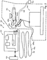
- FIG. 2 is a schematic view of a second embodiment of a compressed gas processing system 901 for compressed gas operated paint shops 902 shown.
- a supply station 921 and a compressed gas source 923 which feeds this, reference is made to the statements relating to that in US Pat FIG. 1 referenced first embodiment shown.
- a spray head 914 is used, which is connected to only one supply line 910.
- the spray head 914 is arranged on a first arm 944a of a manipulator 944 and is moved by the latter during painting according to the requirements.
- An ionizer 913 is in the vicinity of the spray head 914 on a second arm 944b of the manipulator 944, so that a second supply line section 910b with a length A910b is sufficiently long in all positions of the manipulator 944 to allow the spray head 914 and the ionizer 913 without restriction of freedom of movement connect.
- a first supply line section 910a which connects the supply device 921 to the ionization device 913, has a length A910a corresponding to the requirements and ensures by its length that the manipulator 944 can move without restriction in a painting room 945.
- the ionization device 913 includes a high voltage generator 940 and is connected thereto via a multi-wire line 938. According to an embodiment variant, not shown, the line 938 is guided parallel to the first supply line section 910a.
- FIG. 3 a second ionization device 101 is shown in a sectional view.
- the ionization device 101 is used like those in the FIGS. 1 and 2 shown first ionization devices.
- the ionization device 101 comprises a container 102, which has a discharge chamber 103, wherein the discharge chamber 103 is flowed through by compressed gas 104.
- the ionization device 101 comprises two ionization bars 105, 106, which form high-voltage discharge devices 107, 108.
- the ionization bars 105, 106 can each be inserted into the container 102 through a third and a fourth connection 109, 110 such that these sections 111, 112 form a lateral surface 113 of the discharge chamber 103 and thus directly with the compressed gas flowing through the discharge chambers 103 in the flow direction s 104 come into contact.
- the ionizing bars 105, 106 are connected via multi-wire lines, not shown, with a high voltage generator, not shown.
- First and second ports 114, 115 are first and second supply pipe sections of a supply line (not shown) connected. Electrodes 116, 117 of the ionizing rods 105, 106 are in direct contact with the compressed gas 104.
- FIG. 4 a third ionization device 201 is shown in a sectional view.
- the ionization device 201 is used like those in the FIGS. 1 and 2 shown first ionization devices.
- the ionization device 201 comprises a container 202, which has a discharge chamber 203, wherein the discharge chamber 203 is flowed through by the compressed gas 204.
- the ionization device 201 comprises different from that in the FIG. 3 shown ionization device only one Ionticiansstab 205, which forms a high voltage discharge device 207.
- the ionization rod 205 can be inserted into the container 202 by a third connection 209 in such a way that it forms a section 211 of a lateral surface 213 of the discharge chamber 203 and thus comes into direct contact with the compressed gas 204 flowing through the discharge chambers 203 in the flow direction s.
- the ionizing rod 205 is connected via a multicore cable, not shown, with a high voltage generator, not shown.
- Connected to first and second ports 214, 215 are first and second supply line sections of a supply line (not shown). Electrodes 216 of the ionization rod 205 are in direct contact with the pressurized gas 204.
- FIG. 5 is shown as a third embodiment, a compressed gas processing system 401, in which for supplying an explosion-proof paint shop 402b Ionticians wornen 412 and 413, with all its components, namely an ionizing rod 429 and 430, a discharge chamber 427 and 428 and a high voltage generator 439 and 440 within a explosion-proof room or Rb are arranged, in which a guided by a manipulator 444 spray head 414 is located.
- an explosion-proof paint shop 402b Ionmaschines wornen 412 and 413 with all its components, namely an ionizing rod 429 and 430, a discharge chamber 427 and 428 and a high voltage generator 439 and 440 within a explosion-proof room or Rb are arranged, in which a guided by a manipulator 444 spray head 414 is located.
- FIG. 6 is a fourth embodiment variant Druckgasaufkungssystem 501 shown, which analogous to that in the FIG. 1 constructed in the first embodiment, wherein in the fifth embodiment, a spray head 514 is guided by a manipulator 544.
- a compressed gas processing system 601 which is intended for operation in an explosion-proof room Rb, with ionizing 612 and 613 with their components Iontechnischsstab 629 and 630 and discharge chamber 627 and 628 are within the explosion-proof room Rb and only their high voltage generators 639 and 640 are arranged outside the explosion-proof room Rb.
- container 625, 626 in which the ionizing rods and the discharge chambers are installed, arranged on a fixed base 647 of a manipulator 644, from which a spray head 614 is guided.
- FIG. 8 6 shows a compressed gas treatment system 701 which is suitable for operation in an explosion-proof room Rb, with ionization devices 712 and 713 with their ionizing bar 729, 730 and discharge chamber 727, 728 components inside the explosion-proof room Rb and only their high-voltage generators 739, 740 outside the explosion-proof room Rb are arranged.
- containers 725, 726 in which the ionizing rods 729 and 730 and discharge chambers 727 and 728 are installed, in contrast to that in the FIG. 9 shown embodiment, arranged on an arm 744b of a manipulator 744, from which a spray head 714 is guided.
- a pressurized gas treatment system 801 is shown, which is suitable for operation in an explosion-proof room Rb, with ionizing devices 812 and 813 with all their components, namely an ionizing bar 829 or 830, a discharge chamber 827 or 828 and a high voltage generator 839 and 839, respectively 840 within the explosion-proof room Rb.
- containers 825 and 826 in which the ionizing rods 829 and 830 and discharge chambers 827 and 828 are installed, are arranged on an arm 844b of a manipulator 844, from which a spray head 814 is guided.
- the high-voltage generators 839, 840 are connected via electrical cables or multicore cables 837, 838 to the ionizing rods 829, 830 and are arranged stationarily in the explosion-proof room Rb.
Landscapes
- Engineering & Computer Science (AREA)
- Robotics (AREA)
- Electrostatic Spraying Apparatus (AREA)
- Nozzles (AREA)
- Details Or Accessories Of Spraying Plant Or Apparatus (AREA)
Description
- Die Erfindung betrifft ein Druckgasaufbereitungssystem für druckgasbetriebene Beschichtungsanlagen und eine druckgasbetriebene Beschichtungsanlage gemäß dem Oberbegriff des Anspruchs 1, 11 bzw. 12.
- Aus der
DE 10 2011 011 054 A1 ist ein Druckgasaufbereitungssystem bekannt. Dieses Druckgasaufbereitungssystem für druckgasbetriebene Beschichtungsanlagen, umfasst eine Druckgasquelle, eine Versorgungsstation, einen Sprühkopf und eine in der Versorgungsstation verbaute Ionisierungseinrichtung, wobei die Ionisierungseinrichtung eine Entladungskammer, eine Hochspannungsentladungseinrichtung und einen Hochspannungsgenerator umfasst. Es hat sich gezeigt, dass eine Behandlung von Druckgasen mit Hochspannung erheblichen Einfluß auf die Strömungseigenschaften und Anwendungsergebnisse der behandelten Druckgase in der Lackiertechnik aufweisen. Dabei ist es möglicherweise unerheblich, ob die Hochspannungsbehandlung des Druckgases eine Ionisation, eine elektrische Aufladung oder eventuell sogar einen Phasenübergang in eine nicht thermische Plasmaphase bewirkt, je nachdem, welche Eigenschaften beeinflusst bzw. erzielt werden sollen. Bei Anwendung einer langen Zufuhrleitung zu dem Sprühkopf sinkt der Effekt, beispielsweise der Ionisierungsgrad des Druckgases jedoch unter das gewünschte Niveau ab. - Aus der
WO 2009/056950 A1 ist eine Farbsprühvorrichtung bekannt, die eine Ionisierung einer Trägerflüssigkeit beschreibt. Aus derGB 863 190 A EP 0 437 383 A1 offenbart eine Vorrichtung und ein Verfahren zur elektrostatischen Beschichtung von Kunststoffen mit Farbe. Aus derUS 6,684,528 B1 ist System zur Farbtrockung bekannt. - Der Erfindung liegt die Aufgabe zugrunde, ein Druckgasaufbereitungssystem bzw. eine druckgasbetriebene Beschichtungsanlage zu entwickeln, welches bzw. welche auch für einen Betrieb mit einer langen Zufuhrleitungen zwischen der Versorgungsstation und dem Sprühkopf geeignet ist. Diese Aufgabe wird ausgehend von den Merkmalen des Oberbegriffs des Anspruchs 1 bzw. 11 bzw. 12 durch die kennzeichnenden Merkmale des jeweiligen Anspruchs gelöst. In den Unteransprüchen sind vorteilhafte und zweckmäßige Weiterbildungen angegeben.
- Kern der Erfindung liegt darin, eine Hochspannungs-, insbesondere Ionisierungseinrichtung im Druckgasstrang einer Druckgasquelle und der damit einhergehenden Versorgungsstation nachgeschaltet unterzubringen, um die beschriebenen vorteilhaften Effekte möglichst nahe an einem farb-/beschichtungsauftragenden Sprühkopf zur Verfügung zu stellen. Dabei ist vorgesehen, dass zur Verwendung des Druckgasaufbereitungssystems in einem explosionsgeschützten Lackierraum der Beschichtungsanlage die Entladungskammer und die Hochspannungsentladungseinrichtung der Hochspannungs-, insbesondere Ionisierungseinrichtung innerhalb des explosionsgeschützten Lackierraums angeordnet sind.
- Bei dem erfindungsgemäßen Druckgasaufbereitungssystem für druckgasbetriebene Beschichtungsanlagen ist die Hochspannungs-, insbesondere Ionisierungseinrichtung außerhalb der Versorgungsstation angeordnet und ist die Ionisierungseinrichtung der Versorgungsstation im Druckgasstrom nachgeschaltet. Hierdurch ist es möglich, den jeweils erforderlichen Maximalabstand zwischen dem Sprühkopf und der Hochspannungs-, insbesondere Ionisierungseinrichtung unabhängig von der Länge eine Zufuhrleitung zu gewährleisten und so auch die Qualität des Sprühergebnisses sicher zu stellen.
- Unter Druckgasen im Sinne der Erfindung sind diejenigen technischen Gase zu verstehen, welche in der Farbauftrag- bzw. Lackiertechnik oder Beschichtungstechnik (auch Pulverbeschichtung) zum Einsatz kommen.
- Wesentlich für die Erfindung ist, dass der Effekt nicht durch eine elektrostatische Neutralisation der verwendeten Druckgase herbeigeführt wird sondern dass eine tatsächliche Beeinflussung der Strömungseigenschaften und der Transporteigenschaften durch das durchlaufene Hochspanungs-Elektromagnetische Feld generiert wird.
- Weiterhin sieht die Erfindung vor, zur Verwendung des Druckgasaufbereitungssystems in einem explosionsgeschützten Lackierraum der Beschichtungsanlage, den Hochspannungsgenerator der Hochspannungs-, insbesondere Ionisierungseinrichtung außerhalb des explosionsgeschützten Lackierraums anzuordnen, wobei der Hochspannungsgenerator durch elektrische Kabel mit der Hochspannungsentladungseinrichtung verbunden ist. Bei einer derartigen Anordnung der Komponenten ist es möglich, einen herkömmlichen, nicht explosionsgeschützten und damit kostengünstigen Hochspannungsgenerator zu verwenden.
- Alternativ sieht die Erfindung auch vor, zur Verwendung des Druckgasaufbereitungssystems in einem explosionsgeschützten Lackierraum den Hochspannungsgenerator der Hochspannungs-, insbesondere Ionisierungseinrichtung innerhalb des explosionsgeschützten Lackierraums anzuordnen, wobei der Hochspannungsgenerator als explosionsgeschützter Hochspannungsgenerator ausgebildet ist. Eine derartige Anordnung ist einfach aufgebaut und kann insbesondere in dem explosionsgeschützten Lackierraum als kompakte Einheit installiert bzw. bewegt werden.
- Weiterhin sieht die Erfindung vor, entweder durch die Entladungskammer und die Hochspannungsentladungseinrichtung eine Baugruppe zu bilden oder durch die Entladungskammer, die Hochspannungsentladungseinrichtung und den Hochspannungsgenerator eine Baugruppe zu bilden, wobei die jeweils gebildete Baugruppe entweder in den Sprühkopf integriert ist oder an einem Manipulator angeordnet ist, von welchem der Sprühkopf geführt wird, wobei die Baugruppe bei einer Anordnung an dem Manipulator insbesondere an einer im Betrieb bewegten Komponente, insbesondere einem Arm des Manipulators angeordnet ist oder ortsfest in dem explosionsgeschützten Lackierraum angeordnet ist. Derartige Anordnungen lassen sich einfach auf die jeweiligen Anforderungen anpassen.
- Die Erfindung sieht auch vor, im Druckgasstrom vor der Hochspannungs-, insbesondere Ionisierungseinrichtung eine Filtereinrichtung und/oder eine Heizeinrichtung für das Druckgas anzuordnen, wobei die Filtereinrichtung und/oder die Heizeinrichtung außerhalb des explosionsgeschützten Lackierraums und insbesondere in der Versorgungsstation angeordnet ist bzw. sind oder wobei die Filtereinrichtung und/oder die Heizeinrichtung innerhalb des explosionsgeschützten Raums und außerhalb der Versorgungsstation angeordnet ist bzw. sind. Hierdurch lässt sich die Qualität des Druckgases weiter erhöhen.
- Gemäß einer Ausführungsvariante der Erfindung ist es vorgesehen die Beschichtungsanlage zur Verwendung des Druckgasaufbereitungssystems als Nasslackieranlage oder als Pulverbeschichtungsanlage mit einem Nasslackierraum bzw. Beschichtungsraum auszubilden, wobei entweder die Entladungskammer, die Hochspannungsentladungseinrichtung und der Hochspannungsgenerator der Hochspannungs-, insbesondere Ionisierungseinrichtung eine gemeinsame Baugruppe bilden oder wobei ausschließlich die Entladungskammer und die Hochspannungsentladungseinrichtung der Hochspannungs-, insbesondere Ionisierungseinrichtung eine gemeinsame Baugruppe bilden, wobei die gebildete Baugruppe derart in dem Lackierraum bzw. Beschichtungsraum angeordnet ist, dass diese Baugruppe entweder über einen ersten Zufuhrleitungsabschnitt mit der Versorgungsstation und über einen zweiten Zufuhrleitungsabschnitt mit dem Sprühkopf verbunden ist oder dass die gebildete Baugruppe in den Sprühkopf integriert ist.
- Derartige Anordnungen lassen sich einfach auf die jeweiligen Anforderungen anpassen.
- Erfindungsgemäß ist die gebildete Baugruppe entweder an einem Manipulator angeordnet, von welchem der Sprühkopf geführt wird, wobei die Baugruppe bei einer Anordnung an dem Manipulator insbesondere an einer im Betrieb bewegten Komponente, insbesondere einem Arm des Manipulators angeordnet ist oder ist die gebildete Baugruppe ortsfest in dem Lackierraum bzw. Beschichtungsraum angeordnet. Hierdurch ist es möglich die Anlage anforderungsgerecht auszustatten.
- Bei der als Nasslackieranlage oder als Pulverbeschichtungsanlage verwendeten Anlage ist der Hochspannungs-, insbesondere Ionisierungseinrichtung eine Filtereinrichtung und/oder eine Heizeinrichtung vorgeschaltet, wobei die Filtereinrichtung und/oder die Heizeinrichtung entweder in der Versorgungsstation angeordnet ist bzw. sind oder zwischen der Versorgungsstation und der Hochspannungs-, insbesondere Ionisierungseinrichtung angeordnet ist bzw. sind. Hierdurch lässt sich die Qualität des Druckgases weiter erhöhen
- Die Erfindung sieht auch vor, den Zufuhrleitungsabschnitt, welcher die Hochspannungs-, insbesondere Ionisierungseinrichtung und den Sprühkopf verbindet mit einer Länge von höchstens 2,5 m und insbesondere höchstens 0,5 m zu bemessen und diesen Zufuhrleitungsabschnitt in seinem Strömungskanal insbesondere frei von metallischen Einbauteilen wie insbesondere Ventilen und/oder Druckminderern auszubilden. Hierdurch wird einem ungewünschten Abbau des Ionisierungsgrades des Druckgases entgegen gewirkt.
- Die Erfindung sieht vor, dass als Druckgas wahlweise Luft oder Stickstoff Stickstoff-Luft-Gemisch Verwendung findet. Hierdurch sind bei allen drei Systemtypen die sich aus der Erfindung ergebenden Vorteile nutzbar.
- Die erfindungsgemäße, druckgasbetriebene Beschichtungsanlage die als Lackieranlage ausgebildet ist, umfasst ein Druckgasaufbereitungssystem nach Anspruch 1 und zusätzlich insbesondere wenigstens einem der Ansprüche 2 bis 5 oder 10 und weist somit auch deren Vorteile auf.
- Die erfindungsgemäße, druckgasbetriebene Beschichtungsanlage, die als Nasslackieranlage oder Pulverbeschichtungsanlage ausgebildet ist, umfasst ein Druckgasaufbereitungssystem nach Anspruch 6 und zusätzlich insbesondere wenigstens einem der Ansprüche 7 bis 10 und weist somit auch deren Vorteile auf.
- Im Sinne der Erfindung wird unter einer Versorgungsstation eine Druckgasbehandlungs- und/oder Druckgasregelungseinrichtung verstanden, wobei die Versorgungsstation insbesondere durch eine Anordnung, wie insbesondere einen Schrank oder einen Behälter gebildet ist, welche bzw. welcher einen Flansch zum Anschluss einer Zufuhrleitung für einen Sprühkopf aufweist. Hierbei wird eine derartige Versorgungsstation von einer Druckgasquelle mit Druckgas versorgt und wobei die Versorgungsstation insbesondere ein Druckminderer und/oder eine Filtereinrichtung für das Druckgas und/oder eine Heizeinrichtung für das Druckgas umfasst. Hierbei können der Druckminderer und/oder die Filtereinrichtung und/oder die Heizeinrichtung auch baulich getrennt voneinander angeordnet sein. In der kleinsten Ausbaustufe umfasst die Druckgasbehandlungs- und/oder Druckgasregelungseinrichtung nur ein Druckminderer und/oder eine Filtereinrichtung für das Druckgas und/oder eine Heizeinrichtung für das Druckgas.
- Im Sinne der Erfindung wird unter einem Pulverlack insbesondere auch ein Pulveremaillack und unter einem Nasslack insbesondere auch Nassemaillack verstanden
- Im Sinne der Erfindung wird unter einem Manipulator sowohl ein Roboter mit mehreren Bewegungsachsen verstanden als auch ein fest installiertes oder verfahrbares Hubgerüst. Hierbei ist der Sprühkopf bzw. sind die Sprühköpfe entweder fest mit dem Hubgerüst verbunden und werden automatisch mit diesem bewegt oder der Sprühkopf bzw. die Sprühköpfe wird bzw. werden von einer auf dem Hubgerüst befindlichen Person manuell geführt.
- Weitere Einzelheiten der Erfindung werden in der Zeichnung anhand von schematisch dargestellten Ausführungsbeispielen beschrieben. Eine Hochspannungs-, insbesondere Ionisierungsvorrichtung wird im Folgenden Ausführungsbeispiels ausschließlich als Ionisierungseinrichtung bezeichnet, ist jedoch nicht auf diese Ausführung beschränkt. In äquivalenten Ausführungsformen kann an Stelle der Ionisierungseinrichtung eine reinen Hochspannungs-Wechselfeldbehandlung oder eine Hochspannungskammer zur Erzeugung eines nicht thermischen Plasmazustandes treten.
- Hierbei zeigt:
- Figur 1:
- eine schematische Ansicht einer ersten Ausführungsvariante eines Druckgasaufbereitungssystems;
- Figur 2:
- eine schematische Ansicht einer zweiten Ausführungsvariante eines Druckgasaufbereitungssystems;
- Figur 3:
- eine geschnittene Ansicht einer Ionisierungseinrichtung mit einer Hochspannungsentladungsvorrichtung;
- Figur 4:
- eine geschnittene Ansicht einer Ionisierungseinrichtung mit zwei Hochspannungsentladungsvorrichtungen und
- Figur 5 bis 9:
- schematische Ansichten einer dritten bis siebten Ausführungsvariante eines Druckgasaufbereitungssystems.
- In der
Figur 1 ist in schematischer Ansicht eine erste Ausführungsvariante eines Druckgasaufbereitungssystems 1 für druckgasbetriebene Beschichtungsanlagen, welche als Lackieranlagen 2 ausgebildet sind, dargestellt. Das Druckgasaufbereitungssystem 1 umfasst eine Filtereinrichtung 3 zur Reinigung und/oder Trocknung von Druckgas 4, einen Druckminderer 5, einen ersten, zweiten und dritten Flansch 6, 7, 8 zur Ankupplung von Zufuhrleitungen 9, 10 für Verbraucher 11a, 11b, eine erste und eine zweite Ionisierungseinrichtung 12, 13, einen Sprühkopf 14. Als Druckgas findet bei der ersten Ausführungsvariante und bei allen weiteren Ausführungsvarianten wahlweise Luft oder Stickstoff oder ein Stickstoff-Luft-Gemisch Verwendung. Der Sprühkopf 14 weist eine erste Öffnung 15 zum Austritt von Druckgas und eine zweite Öffnung 16 zum Austritt von Druckgas und Farbe auf, wobei die Öffnungen 15, 16 die Verbraucher 11a, 11b bilden. Die Ionisierungseinrichtungen 12, 13 umfassen jeweils eine Hochspannungsentladungsvorrichtung 17, 18, an der das Druckgas 4 zumindest teilweise vorbeiströmt. Hierbei sind die Zufuhrleitungen 9, 10 zweiteilig ausgebildet und umfassen jeweils einen ersten Zufuhrleitungsabschnitt 9a bzw. 10a und einen zweiten Zufuhrleitungsabschnitt 9b bzw. 10b. Der erste Zufuhrleitungsabschnitt 9a bzw. 10a ist jeweils zwischen dem erwähnten Flansch 6 bzw. 7 und ersten Anschlüssen 12a bzw. 13a der Ionisierungseinrichtungen 12 bzw. 13 angeordnet. Der zweite Zufuhrleitungsabschnitt 9b bzw. 10b ist jeweils zwischen zweiten Anschlüssen 12b bzw. 13b der Ionisierungseinrichtungen 12 bzw. 13 und Flanschen 19 bzw. 20 des Sprühkopfs 14 angeordnet. Die Filtereinrichtung 3 und der Druckminderer 5 sind Bestandteil einer Versorgungsstation 21, welche neben den Flanschen 6, 7, 8 zu Abgabe von Druckgas noch einen weiteren Flansche 22 umfasst, über welchen die Versorgungsstation 21 von einem Druckgasquelle 23 mit Druckgas gespeist wird. Die Zufuhrleitungsabschnitte 9a und 9b weisen Längen A9a und A9b auf. Die Zufuhrleitungsabschnitte 10a und 10b weisen Längen A10a und A10b auf. Die Längen A9b und A10b der zweiten Zufuhrabschnitte 9b und 10b, welche die Ionisierungseinrichtung 12, 13 mit dem Sprühkopf 14 verbinden sind derart bemessen, dass ein dauerhaft hinreichender Ionisierungsgrad des Druckgases in dem Sprühkopf 14 ankommt, um Qualitätsschwankungen zu vermeiden. Gemäß einer bevorzugten Ausführungsvariante ist es vorgesehen, in der Versorgungsstation 21 noch eine Heizeinrichtung 24 in den Druckgasstrom zu schalten, um eine konstante Temperatur des an die Ionisiereinrichtungen 12, 13 strömenden Druckgases sicher zu stellen. Die beiden Ionisiereinrichtungen 12, 13 umfassen jeweils einen Behälter 25, 26, in welchem eine Entladungskammer 27 bzw. 28 angeordnet ist, wobei die Entladungskammer 27 bzw. 28 von dem Druckgas 4 durchströmt wird. Weiterhin umfassen die Ionisierungseinrichtungen 12, 13 jeweils einen Ionisierungsstab 29 bzw. 30, welcher die erwähnte Hochspannungsentladungsvorrichtung 17 bzw. 18 bildet. Hierbei sind die Ionisierungsstäbe 29, 30 jeweils durch einen dritten Anschluss 31 bzw. 32 derart in die Behälter 25 bzw. 26 angeordnet. Die Ionisierungsstäbe bilden jeweils einen Abschnitt 33 bzw. 34 einer Mantelfläche 35 bzw. 36 der Entladungskammer 27 bzw. 28 und kommen so direkt mit dem die Entladungskammern 27 bzw. 28 in Strömungsrichtung s durchströmenden Druckgas 4 in Kontakt. Die Ionisierungsstäbe 29, 30 sind jeweils über elektrische Kabel bzw. mehradrige Leitung 37 bzw. 38 mit Hochspannungsquellen bzw. Hochspannungsgeneratoren 39 bzw. 40 verbunden. Dem über den zweiten Zufuhrleitungsabschnitt 10b zugeführten, ionisierten Druckgas wird in der Sprüheinrichtung 14 Farbe 41 beigemischt, so dass ein Farbstrahl 42 gebildet wird. Das über den zweiten Zufuhrleitungsabschnitt 9b zugeführte, ionisierte Druckgas durchströmt die Sprüheinrichtung 14 und tritt aus dieser als reiner Druckgasstahl 43 aus, um den Farbstahl 42 seitlich zu begrenzen. - In der
Figur 2 ist in schematischer Ansicht eine zweite Ausführungsvariante eines Druckgasaufbereitungssystems 901 für druckgasbetriebene Lackieranlagen 902 dargestellt. Bezüglich der Ausführung einer Versorgungsstation 921 und eine diese speisenden Druckgasquelle 923 wird auf die Ausführungen zu der in derFigur 1 gezeigten ersten Ausführungsvariante verwiesen. Im Unterschied zu der ersten Ausführungsvariante kommt bei der zweiten Ausführungsvariante eine Sprühkopf 914 zum Einsatz, welcher an nur eine Zufuhrleitung 910 angeschlossen ist. Der Sprühkopf 914 ist an einem ersten Arm 944a eines Manipulators 944 angeordnet und wird von diesem beim Lackieren entsprechend den Anforderungen bewegt. Eine Ionisierungseinrichtung 913 ist in der Nähe des Sprühkopfes 914 an einem zweiten Arm 944b des Manipulators 944 angeordnet, so dass ein zweiter Zufuhrleitungsabschnitt 910b mit eine Länge A910b in allen Stellungen des Manipulators 944 ausreichend lang bemessen ist, um den Sprühkopf 914 und die Ionisierungseinrichtung 913 ohne Einschränkung der Bewegungsfreiheit zu verbinden. Ein erster Zufuhrleitungsabschnitt 910a, welcher die Versorgungseinrichtung 921 mit der Ionisierungseinrichtung 913 verbindet, weist eine den Anforderungen entsprechende Länge A910a auf und stellt durch seine Länge sicher, dass sich der Manipulator 944 in einem Lackierraum 945 ohne Einschränkung bewegen kann. Bezüglich des Aufbaus der Ionisierungseinrichtung 913 wird ebenfalls auf die Beschreibung zurFigur 1 verwiesen. Die Ionisierungseinrichtung 913 umfasst einen Hochspannungsgenerator 940 und ist mit dieser über eine mehradrige Leitung 938 verbunden. Gemäß einer nicht dargestellten Ausführungsvariante ist die Leitung 938 parallel zu dem ersten Zufuhrleitungsabschnitt 910a geführt. - In der
Figur 3 ist eine zweite Ionisierungseinrichtung 101 in geschnittener Darstellung gezeigt. Die Ionisierungseinrichtung 101 findet Verwendung wie die in denFiguren 1 und2 gezeigten ersten Ionisierungseinrichtungen. Die Ionisierungseinrichtung 101 umfasst einen Behälter 102, welcher eine Entladungskammer 103 aufweist, wobei die Entladungskammer 103 von Druckgas 104 durchströmt wird. Weiterhin umfasst die Ionisierungseinrichtungen 101 zwei Ionisierungsstäbe 105, 106, welcher Hochspannungsentladungsvorrichtungen 107, 108 bilden. Die Ionisierungsstäbe 105, 106 sind jeweils durch einen dritten und einen vierten Anschluss 109, 110 derart in den Behälter 102 einschiebbar, dass diese Abschnitte 111, 112 einer Mantelfläche 113 der Entladungskammer 103 bilden und so direkt mit dem die Entladungskammern 103 in Strömungsrichtung s durchströmenden Druckgas 104 in Kontakt kommen. Die Ionisierungsstäbe 105, 106 sind über nicht dargestellte mehradrige Leitungen mit einem nicht dargestellten Hochspannungsgenerator verbunden. An erste und zweite Anschlüsse 114, 115 sind ein erster und ein zweiter Zufuhrleitungsabschnitt einer nicht dargstellten Zufuhrleitung angeschlossen. Elektroden 116, 117 der Ionisierungsstäbe 105, 106 stehen in direktem Kontakt mit dem Druckgas 104. - In der
Figur 4 ist eine dritte Ionisierungseinrichtung 201 in geschnittener Darstellung gezeigt. Die Ionisierungseinrichtung 201 findet Verwendung wie die in denFiguren 1 und2 gezeigten ersten Ionisierungseinrichtungen. Die Ionisierungseinrichtung 201 umfasst einen Behälter 202, welcher eine Entladungskammer 203 aufweist, wobei die Entladungskammer 203 von dem Druckgas 204 durchströmt wird. Weiterhin umfasst die Ionisierungseinrichtungen 201 im Unterschied zu der in derFigur 3 gezeigten Ionisierungseinrichtung nur einen Ionisierungsstab 205, welcher eine Hochspannungsentladungsvorrichtung 207 bildet. Der Ionisierungsstab 205 ist durch einen dritten Anschluss 209 derart in den Behälter 202 einschiebbar, dass dieser einen Abschnitt 211 einer Mantelfläche 213 der Entladungskammer 203 bildet und so direkt mit dem die Entladungskammern 203 in Strömungsrichtung s durchströmenden Druckgas 204 in Kontakt kommt. Der Ionisierungsstab 205 ist über eine nicht dargestellte mehradrige Leitung mit einem nicht dargestellten Hochspannungsgenerator verbunden. An erste und zweite Anschlüsse 214, 215 sind ein erster und ein zweiter Zufuhrleitungsabschnitt einer nicht dargstellten Zufuhrleitung angeschlossen. Elektroden 216 des Ionisierungsstabs 205 stehen in direktem Kontakt mit dem Druckgas 204. - In der
Figur 5 ist als dritte Ausführungsvariante ein Druckgasaufbereitungssystem 401 gezeigt, bei welchem zur Versorgung einer explosionsgeschützten Lackieranlage 402b Ionisierungseinrichtungen 412 und 413, mit all ihren Komponenten, nämlich einem Ionisierungsstab 429 bzw. 430, einer Entladungskammer 427 bzw. 428 und einem Hochspannungsgenerator 439 bzw. 440 innerhalb eines explosionsgeschützten Raums bzw. Lackierraums Rb angeordnet sind, in welchem sich ein von einem Manipulator 444 geführter Sprühkopf 414 befindet. - In der
Figur 6 ist als vierte Ausführungsvariante ein Druckgasaufbereitungssystem 501 gezeigt, welches analog zu der in derFigur 1 gezeigten ersten Ausführungsvariante aufgebaut ist, wobei bei der fünften Ausführungsvariante ein Sprühkopf 514 von einem Manipulator 544 geführt wird. - In der
Figur 7 ist als fünfte Ausführungsvariante ein Druckgasaufbereitungssystem 601 gezeigt, welches zum Betrieb in einem explosionsgeschützten Raum Rb vorgesehen ist, wobei sich Ionisierungseinrichtungen 612 und 613 mit ihren Komponenten Ionisierungsstab 629 bzw. 630 und Entladungskammer 627 bzw. 628 innerhalb des explosionsgeschützten Raums Rb befinden und nur deren Hochspannungsgeneratoren 639 und 640 außerhalb des explosionsgeschützten Raums Rb angeordnet sind. Hierbei sind Behälter 625, 626, in welchem die Ionisierungsstäbe und die Entladungskammern eingebaut sind, an einem feststehenden Sockel 647 eines Manipulators 644 angeordnet, von welchem ein Sprühkopf 614 geführt wird. - In der
Figur 8 ist als sechste Ausführungsvariante ein Druckgasaufbereitungssystem 701 gezeigt, welches zum Betrieb in einem explosionsgeschützten Raum Rb geeignet ist, wobei sich Ionisierungseinrichtungen 712 und 713 mit ihren Komponenten Ionisierungsstab 729, 730 und Entladungskammer 727, 728 innerhalb des explosionsgeschützten Raums Rb befinden und nur deren Hochspannungsgeneratoren 739, 740 außerhalb des explosionsgeschützten Raums Rb angeordnet sind. Hierbei sind Behälter 725, 726, in welche die Ionisierungsstäbe 729 bzw. 730 und Entladungskammern 727 bzw. 728 eingebaut sind, im Unterschied zu der in derFigur 9 gezeigten Ausführungsvariante, an einem Arm 744b eines Manipulators 744 angeordnet, von welchem ein Sprühkopf 714 geführt wird. - In der
Figur 9 ist als siebte Ausführungsvariante ein Druckgasaufbereitungssystem 801 gezeigt, welches zum Betrieb in einem explosionsgeschützten Raum Rb geeignet ist, wobei sich Ionisierungseinrichtungen 812 und 813 mit all ihren Komponenten, nämlich einem Ionisierungsstab 829 bzw. 830, einer Entladungskammer 827 bzw. 828 und einem Hochspannungsgenerator 839 bzw. 840 innerhalb des explosionsgeschützten Raums Rb befinden. Hierbei sind Behälter 825 bzw. 826, in welche die Ionisierungsstäbe 829 bzw. 830 und Entladungskammern 827 bzw. 828 eingebaut sind, an einem Arm 844b eines Manipulators 844 angeordnet, von welchem ein Sprühkopf 814 geführt wird. Die Hochspannungsgeneratoren 839, 840 sind über elektrisch Kabel bzw. mehradrige Leitungen 837, 838 mit den Ionisierungsstäben 829, 830 verbunden und ortsfest in dem explosionsgeschützten Raum Rb angeordnet. - Die Erfindung ist nicht auf dargestellte oder beschriebene Ausführungsbeispiele beschränkt. Sie umfasst vielmehr Weiterbildungen der Erfindung im Rahmen der Schutzrechtsansprüche.
-
- 1
- Druckgasaufbereitungssystem
- 2
- Lackieranlage
- 3
- Filtereinrichtung
- 4
- Druckgas
- 5
- Druckminderer
- 6, 7, 8
- Flansch an 21
- 9, 10
- Zufuhrleitung
- 9a, 10a
- erster Zufuhrleitungsabschnitt von 9 bzw. 10
- 9b, 10b
- zweiter Zufuhrleitungsabschnitt von 9 bzw. 10
- 11a, 11b
- Verbraucher für Druckgas
- 12, 13
- Ionisierungseinrichtung
- 12a, 13a
- erster Anschluss von 12 bzw. 13
- 12b, 13b
- zweiter Anschluss von 12 bzw. 13
- 14
- Sprühkopf
- 15
- erste Öffnung von 14
- 16
- zweite Öffnung von 14
- 17, 18
- Hochspannungsentladungsvorrichtung
- 19, 20
- Flansch an 14
- 21
- Versorgungsstation
- 22
- weiterer Flansch an 21
- 23
- Druckgasquelle
- 24
- Heizeinrichtung
- 25, 26
- Behälter
- 27, 28
- Entladungskammer
- 29, 30
- Ionisierungsstab
- 31, 32
- dritter Anschluss
- 33, 34
- Abschnitt von 35 bzw. 36
- 35, 36
- Mantelfläche von 27 bzw. 28
- 37, 38
- mehradrige Leitung bzw. el. Kabel zu 39, 40
- 39, 40
- Hochspannungsgenerator
- 41
- Farbe
- 42
- Farbstrahl
- 43
- Druckgasstrahl
- 44
- Manipulator
- 44a, 44b
- Arm von 44
- 45
- Lackierraum
- 101
- Ionisierungseinrichtung
- 102
- Behälter
- 103
- Entladungskammer
- 104
- Druckgas
- 105, 106
- Ionisierungsstab
- 107, 108
- Hochspannungsentladungsvorrichtung
- 109, 110
- dritter, vierter Anschluss an 102
- 111, 112
- Abschnitt von 113
- 113
- Mantelfläche
- 114, 115
- erster, zweiter Anschluss an 102
- 116, 117
- Elektrode
- 201
- Ionisierungseinrichtung
- 202
- Behälter
- 203
- Entladungskammer
- 204
- Druckgas
- 205
- Ionisierungsstab
- 207
- Hochspannungsentladungsvorrichtung
- 209
- dritter Anschluss an 202
- 211
- Abschnitt von 213
- 213
- Mantelfläche
- 214, 215
- erster, zweiter Anschluss an 202
- 216
- Elektrode
- 401
- Druckgasaufbereitungssystem
- 402b
- explosionsgeschützte Lackieranlage
- 412, 413
- Ionisierungseinrichtung
- 414
- Sprühkopf
- 427, 428
- Entladungskammer
- 429, 430
- Ionisierungsstab
- 439, 440
- Hochspannungsgenerator
- 444
- Manipulator
- 501
- Druckgasaufbereitungssystem
- 514
- Sprühkopf
- 544
- Manipulator
- 601
- Druckgasaufbereitungssystem
- 612, 613
- Ionisierungseinrichtung
- 614
- Sprühkopf
- 625, 626
- Behälter
- 629, 630
- Ionisierungsstab
- 639, 640
- Hochspannungsgenerator
- 644
- Manipulator
- 647
- feststehender Sockel
- 701
- Druckgasaufbereitungssystem
- 712, 713
- Ionisierungseinrichtung
- 714
- Sprühkopf
- 725, 726
- Behälter
- 727, 728
- Entladungskammer
- 729, 730
- Ionisierungsstab
- 739, 740
- Hochspannungsgenerator
- 744
- Manipulator
- 744b
- Arm
- 801
- Druckgasaufbereitungssystem
- 812, 813
- Ionisierungseinrichtung
- 814
- Sprühkopf
- 825, 826
- Behälter
- 827, 828
- Entladungskammer
- 829, 830
- Ionisierungsstab
- 837, 838
- mehradrige Leitung bzw. el. Kabel
- 839, 840
- Hochspannungsgenerator
- 844
- Manipulator
- 844b
- Arm
- 901
- Druckgasaufbereitungssystem
- 902
- druckgasbetriebene Lackieranlage
- 910
- Zufuhrleitung
- 910a
- erster Zufuhrleitungsabschnitt von 910
- 910b
- zweiter Zufuhrleitungsabschnitt von 910
- 913
- Ionisierungseinrichtung
- 914
- Sprühkopf
- 921
- Versorgungsstation
- 923
- Druckgasquelle
- 938
- mehradrige Leitung
- 940
- Hochspannungsgenerator
- 944
- Manipulator
- 944a
- erster Arm von 944
- 944b
- zweiter Arm von 944
- 945
- Lackierraum
- A9a, A10a
- Länge von 9a bzw. 10a
- A9b, A10b
- Länge von 9b bzw. 10b
- A910a
- Länge von 910a
- A910b
- Länge von 910b
- Rb
- explosionsgeschützter Raum bzw. Lackierraum
- s
- Strömungsrichtung
Claims (13)
- Druckgasaufbereitungssystem (1; 301; 401; 501; 601; 701; 801; 901) für druckgasbetriebene Beschichtungsanlagen umfassend- eine Druckgasquelle (23; 923),- eine Versorgungsstation (21; 321; 921), welche von der Druckgasquelle (23; 923) mit Druckgas (4; 104; 204) versorgt wird,- wenigstens einen Sprühkopf (14; 314; 346; 414; 514; 614; 714; 814; 914),- mindestens eine Hochspannungs-, insbesondere Ionisierungseinrichtung (12, 13; 101; 201; 312; 313; 412; 413; 612; 613; 712; 713; 812; 813; 913),- wobei die Hochspannungs-, insbesondere Ionisierungseinrichtung (12, 13; 101; 201; 312; 313; 412; 413; 612; 613; 712; 713; 812; 813; 913) eine Entladungskammer (27, 28; 427, 428; 727, 728; 827, 828), eine Hochspannungsentladungseinrichtung (17, 18; 107, 108; 207) und einen Hochspannungsgenerator (39, 40; 439, 440; 639, 640; 739, 740; 839, 840) umfasst,- wobei die Hochspannungs-, insbesondere Ionisierungseinrichtung (12, 13; 101; 201; 312; 313; 412; 413; 612; 613; 712; 713; 812; 813; 913) außerhalb der Versorgungsstation (21; 321; 921) angeordnet ist und wobei die Hochspannungs-, insbesondere Ionisierungseinrichtung (12, 13; 101; 201; 312; 313; 412; 413; 612; 613; 712; 713; 812; 813; 913) der Versorgungsstation (21; 321; 921) im Strom des Druckgases (4; 104; 204) nachgeschaltet ist,dadurch gekennzeichnet,- dass zur Verwendung des Druckgasaufbereitungssystems (1; 301; 401; 501; 601; 701; 801; 901) in einem explosionsgeschützten Lackierraum (Rb) der Beschichtungsanlage die Entladungskammer (27, 28; 427, 428; 727, 728; 827, 828) und die Hochspannungsentladungseinrichtung (17, 18; 107, 108; 207) der Hochspannungs-, insbesondere Ionisierungseinrichtung (12, 13; 101; 201; 312; 313; 412; 413; 612; 613; 712; 713; 812; 813; 913) innerhalb des explosionsgeschützten Lackierraums (Rb) angeordnet sind.
- Druckgasaufbereitungssystem (1; 301; 401; 501; 601; 701; 801; 901) nach Anspruch 1, dadurch gekennzeichnet,- dass zur Verwendung des Druckgasaufbereitungssystems (1; 301; 401; 501; 601; 701; 801; 901) in einem explosionsgeschützten Lackierraum (Rb) der Beschichtungsanlage der Hochspannungsgenerator (39, 40; 439, 440; 639, 640; 739, 740; 839, 840) der Hochspannungs-, insbesondere Ionisierungseinrichtung (12, 13; 101; 201; 312; 313; 412; 413; 612; 613; 712; 713; 812; 813; 913) außerhalb des explosionsgeschützten Lackierraums (Rb) angeordnet ist,- wobei der Hochspannungsgenerator (39, 40; 439, 440; 639, 640; 739, 740; 839, 840) durch elektrische Kabel (37, 38; 837, 838) mit der Hochspannungsentladungseinrichtung (17, 18; 107, 108; 207) verbunden ist.
- Druckgasaufbereitungssystem (1; 301; 401; 501; 601; 701; 801; 901) (1) nach Anspruch 1 dadurch gekennzeichnet, dass zur Verwendung des Druckgasaufbereitungssystems (1; 301; 401; 501; 601; 701; 801; 901) in einem explosionsgeschützten Lackierraum (Rb) der Hochspannungsgenerator (39, 40; 439, 440; 639, 640; 739, 740; 839, 840) der Hochspannungs-, insbesondere Ionisierungseinrichtung (12, 13; 101; 201; 312; 313; 412; 413; 612; 613; 712; 713; 812; 813; 913) innerhalb des explosionsgeschützten Lackierraums (Rb) angeordnet ist, wobei der Hochspannungsgenerator (39, 40; 439, 440; 639, 640; 739, 740; 839, 840) als explosionsgeschützter Hochspannungsgenerator (39, 40; 439, 440; 639, 640; 739, 740; 839, 840) ausgebildet ist.
- Druckgasaufbereitungssystem (1; 301; 401; 501; 601; 701; 801; 901) nach Anspruch 2 oder 3, dadurch gekennzeichnet, dass die Entladungskammer (27, 28; 427, 428; 727, 728; 827, 828) und die Hochspannungsentladungseinrichtung (17, 18; 107, 108; 207) eine Baugruppe bilden oder dass die Entladungskammer (27, 28; 427, 428; 727, 728; 827, 828) und die Hochspannungsentladungseinrichtung (17, 18; 107, 108; 207) und der Hochspannungsgenerator (39, 40; 439, 440; 639, 640; 739, 740; 839, 840) eine Baugruppe bilden, wobei die jeweils gebildete Baugruppe- in den Sprühkopf (14; 314; 346; 414; 514; 614; 714; 814; 914) integriert ist oder- an einem Manipulator (44; 444; 544; 644; 744; 844; 944) angeordnet ist, von welchem der Sprühkopf (14; 314; 346; 414; 514; 614; 714; 814; 914) geführt wird,- wobei die Baugruppe bei einer Anordnung an dem Manipulator (44; 444; 544; 644; 744; 844; 944) insbesondere an einer im Betrieb bewegten Komponente, insbesondere einem Arm (44a, 44b; 744b; 844b; 944a, 944b) des Manipulators (44; 444; 544; 644; 744; 844; 944) angeordnet ist oder ortsfest in dem explosionsgeschützten Lackierraum (Rb) angeordnet ist.
- Druckgasaufbereitungssystem (1; 301; 401; 501; 601; 701; 801; 901) nach einem der vorhergehenden Ansprüche, dadurch gekennzeichnet, dass- der Hochspannungs-, insbesondere Ionisierungseinrichtung (12, 13; 101; 201; 312; 313; 412; 413; 612; 613; 712; 713; 812; 813; 913) eine Filtereinrichtung (3) und/oder eine Heizeinrichtung (24) vorgeschaltet ist bzw. sind,- wobei die Filtereinrichtung (3) und/oder die Heizeinrichtung (24) außerhalb des explosionsgeschützten Lackierraums (Rb) und insbesondere in der Versorgungsstation (21; 321; 921) angeordnet ist bzw. sind oder- wobei die Filtereinrichtung (3) und/oder die Heizeinrichtung (24) innerhalb des explosionsgeschützten Lackierraums (Rb) und außerhalb der Versorgungsstation (21; 321; 921) angeordnet ist bzw. sind.
- Druckgasaufbereitungssystem (1; 301; 401; 501; 601; 701; 801; 901) nach Anspruch 1, dadurch gekennzeichnet, dass- die Beschichtungsanlage zur Verwendung des Druckgasaufbereitungssystems (1; 301; 401; 501; 601; 701; 801; 901) als Nasslackieranlage (302a) oder als Pulverbeschichtungsanlage (302b) mit einem Nasslackierraum bzw. Beschichtungsraum ausgebildet ist,- wobei entweder die Entladungskammer (27, 28; 427, 428; 727, 728; 827, 828), die Hochspannungsentladungseinrichtung (17, 18; 107, 108; 207) und der Hochspannungsgenerator (39, 40; 439, 440; 639, 640; 739, 740; 839, 840) der Hochspannungs-, insbesondere Ionisierungseinrichtung (12, 13; 101; 201; 312; 313; 412; 413; 612; 613; 712; 713; 812; 813; 913) eine gemeinsame Baugruppe bilden oder- wobei die Entladungskammer (27, 28; 427, 428; 727, 728; 827, 828) und die Hochspannungsentladungseinrichtung (17, 18; 107, 108; 207) der Hochspannungs-, insbesondere Ionisierungseinrichtung (12, 13; 101; 201; 312; 313; 412; 413; 612; 613; 712; 713; 812; 813; 913) eine gemeinsame Baugruppe bilden,- wobei die gebildete Baugruppe derart in dem Lackierraum bzw. Beschichtungsraum angeordnet ist, dass diese Baugruppe- entweder über einen ersten Zufuhrleitungsabschnitt (9a, 10a) mit der Versorgungsstation (21; 321; 921) und über einen zweiten Zufuhrleitungsabschnitt (9b, 10b) mit dem Sprühkopf (14; 314; 346; 414; 514; 614; 714; 814; 914) verbunden ist oder- dass die gebildete Baugruppe in den Sprühkopf (14; 314; 346; 414; 514; 614; 714; 814; 914) integriert ist.
- Druckgasaufbereitungssystem (1; 301; 401; 501; 601; 701; 801; 901) nach Anspruch 6, dadurch gekennzeichnet,- dass die gebildete Baugruppe entweder an einem Manipulator (44; 444; 544; 644; 744; 844; 944) angeordnet ist, von welchem der Sprühkopf (14; 314; 346; 414; 514; 614; 714; 814; 914) geführt wird, wobei die Baugruppe bei einer Anordnung an dem Manipulator (44; 444; 544; 644; 744; 844; 944) insbesondere an einer im Betrieb bewegten Komponente, insbesondere einem Arm (44a, 44b; 744b; 844b; 944a, 944b) des Manipulators (44; 444; 544; 644; 744; 844; 944) angeordnet ist oder- dass die gebildete Baugruppe ortsfest in dem Lackierraum bzw. Beschichtungsraum angeordnet ist.
- Druckgasaufbereitungssystem (1; 301; 401; 501; 601; 701; 801; 901) nach Anspruch 6 oder 7, dadurch gekennzeichnet,- dass der Hochspannungs-, insbesondere Ionisierungseinrichtung (12, 13; 101; 201; 312; 313; 412; 413; 612; 613; 712; 713; 812; 813; 913) eine Filtereinrichtung (3) und/oder Heizeinrichtung (24) vorgeschaltet ist bzw. sind, wobei die Filtereinrichtung (3) und/oder die Heizeinrichtung (24)- entweder in der Versorgungsstation (21; 321; 921) angeordnet ist bzw. sind- oder zwischen der Versorgungsstation (21; 321; 921) und der Ionisierungseinrichtung (12, 13; 101; 201; 312; 313; 412; 413; 612; 613; 712; 713; 812; 813; 913) angeordnet ist bzw. sind.
- Druckgasaufbereitungssystem (1; 301; 401; 501; 601; 701; 801; 901) nach einem der vorhergehenden Ansprüche, dadurch gekennzeichnet, dass der Zufuhrleitungsabschnitt (9b, 10b), welche die Hochspannungs-, insbesondere Ionisierungseinrichtung (12, 13; 101; 201; 312; 313; 412; 413; 612; 613; 712; 713; 812; 813; 913) und den Sprühkopf (14; 314; 346; 414; 514; 614; 714; 814; 914) verbindet eine Länge (A9b, A10b; A910a; A910b) von höchstens 2,5 m und insbesondere höchstens 0,5 m aufweist und wobei dieser Zufuhrleitungsabschnitt (9b, 10b; 910b) in seinem Strömungskanal insbesondere frei von metallischen Einbauteilen wie insbesondere Ventilen und/oder Druckminderern ist.
- Druckgasaufbereitungssystem nach wenigstens einem der vorhergehenden Ansprüche, dadurch gekennzeichnet, dass als Druckgas wahlweise Luft oder Stickstoff oder ein Stickstoff-Luft-Gemisch Verwendung findet.
- Druckgasbetriebene Beschichtungsanlage wie Lackieranlage umfassend einen explosionsgeschützten Lackierraum (Rb), eine Druckgasquelle (23; 923) und wenigstens einen Sprühkopf (314; 346), dadurch gekennzeichnet, dass die Beschichtungsanlage ein Druckgasaufbereitungssystem (1; 301; 401; 501; 601; 701; 801; 901) nach Anspruch 1 und zusätzlich insbesondere wenigstens einem der Ansprüche 2 bis 5 oder 10 umfasst.
- Druckgasbetriebene Beschichtungsanlage wie Nasslackieranlage oder Pulverbeschichtungsanlage umfassend einen Nasslackierraum bzw. Beschichtungsraum, eine Druckgasquelle (223) und wenigstens einen Sprühkopf (314; 346), dadurch gekennzeichnet, dass die Beschichtungsanlage ein Druckgasaufbereitungssystem (301) nach Anspruch 6 und zusätzlich insbesondere wenigstens einem der Ansprüche 7 bis 10 umfasst.
- Druckgasaufbereitungssystem nach einem der Ansprüche 1 bis 10, dadurch gekennzeichnet, dass die Hochspannungs-, insbesondere Ionisierungseinrichtung (12, 13; 312; 313; 913) entweder durch einen ersten Zufuhrleitungsabschnitt (9a, 10a; 309a; 910a) mit der Versorgungsstation (21; 321; 921) und durch einen zweiten Zufuhrleitungsabschnitt (9b, 10b; 309b; 910b) mit dem Sprühkopf (14; 314; 346; 914) verbunden ist oder dass die Hochspannungs-, insbesondere Ionisierungseinrichtung in den Sprühkopf integriert ist und durch die Zufuhrleitung mit der Versorgungsstation verbunden ist.
Applications Claiming Priority (2)
| Application Number | Priority Date | Filing Date | Title |
|---|---|---|---|
| DE202012012185.5U DE202012012185U1 (de) | 2012-12-20 | 2012-12-20 | Druckgasaufbereitungssystem für druckgasbetriebene Beschichtungsanlagen und druckgasbetriebene Beschichtungsanlage |
| PCT/EP2013/003896 WO2014095081A2 (de) | 2012-12-20 | 2013-12-20 | Druckgasaufbereitungssystem für druckgasbetriebene beschichtungsanlagen und druckgasbetriebene beschichtungsanlage |
Publications (2)
| Publication Number | Publication Date |
|---|---|
| EP2934725A2 EP2934725A2 (de) | 2015-10-28 |
| EP2934725B1 true EP2934725B1 (de) | 2018-08-08 |
Family
ID=50071566
Family Applications (1)
| Application Number | Title | Priority Date | Filing Date |
|---|---|---|---|
| EP13828912.9A Active EP2934725B1 (de) | 2012-12-20 | 2013-12-20 | Druckgasaufbereitungssystem und druckgasbetriebene beschichtungsanlage |
Country Status (6)
| Country | Link |
|---|---|
| US (1) | US20150352567A1 (de) |
| EP (1) | EP2934725B1 (de) |
| CN (1) | CN105228727B (de) |
| DE (1) | DE202012012185U1 (de) |
| MX (1) | MX351019B (de) |
| WO (1) | WO2014095081A2 (de) |
Families Citing this family (6)
| Publication number | Priority date | Publication date | Assignee | Title |
|---|---|---|---|---|
| ITFI20130286A1 (it) * | 2013-11-25 | 2015-05-26 | Eurosider Sas Di Milli Ottavio & C | Apparato automatico di verniciatura pneumatica. |
| EP2933024A1 (de) * | 2014-04-14 | 2015-10-21 | Luciano Simonato | Anlage zur Spritzlackierung |
| GB2553787A (en) * | 2016-09-13 | 2018-03-21 | Haydell Michael | A conditioning apparatus for providing a carrier gas |
| WO2019020796A2 (de) * | 2017-07-28 | 2019-01-31 | Thomas Mayer | Vorrichtung zur bereitstellung von druckgas an einer mit druckgas arbeitenden sprühvorrichtung, verfahren zur bereitstellung von druckgas an einer mit druckgas arbeitenden sprühvorrichtung sowie verfahren zum versprühen eines flüssigen mediums |
| CN110506973A (zh) * | 2019-10-14 | 2019-11-29 | 中国烟草总公司郑州烟草研究院 | 一种向造纸法再造烟叶中施加烟粉的方法 |
| CN110679992B (zh) * | 2019-10-14 | 2021-08-17 | 河南卷烟工业烟草薄片有限公司 | 一种烟粉喷送分散特性的测量系统及测量方法 |
Family Cites Families (9)
| Publication number | Priority date | Publication date | Assignee | Title |
|---|---|---|---|---|
| US3017119A (en) * | 1955-09-13 | 1962-01-16 | Air Reduction | Apparatus for metal spraying |
| US2890388A (en) * | 1955-11-30 | 1959-06-09 | Gen Motors Corp | Electrostatic spray charger |
| GB863190A (en) * | 1958-06-30 | 1961-03-15 | Metco Inc | Heat-fusible material spray gun and method for coating a surface with a heat-fusiblematerial |
| CN86200692U (zh) * | 1986-02-04 | 1987-09-12 | 刘国栋 | 喷涂离子化附加器 |
| EP0437383A1 (de) * | 1990-01-12 | 1991-07-17 | Regie Nationale Des Usines Renault S.A. | Verfahren und Vorrichtung zum elektrostatischen Spritzlackieren von Kunststoffgegenständen |
| PT1242779E (pt) * | 1999-04-21 | 2005-08-31 | Junair Group Ltd | Sistema de secagem de pintura |
| WO2009056950A1 (en) * | 2007-10-31 | 2009-05-07 | Eurosider Sas | Spray painting device with ionization of the carrier fluid |
| CN101928994B (zh) * | 2010-07-13 | 2014-07-23 | 三河厚德光机电有限公司 | 一种恒温喷丝板及其制造方法 |
| DE102011011054B4 (de) | 2011-02-11 | 2023-01-26 | Thomas Mayer | Verfahren zur Aufbereitung von Druckluft sowie Vorrichtung zur Aufbereitung von Druckluft |
-
2012
- 2012-12-20 DE DE202012012185.5U patent/DE202012012185U1/de not_active Expired - Lifetime
-
2013
- 2013-12-20 MX MX2015007964A patent/MX351019B/es active IP Right Grant
- 2013-12-20 EP EP13828912.9A patent/EP2934725B1/de active Active
- 2013-12-20 WO PCT/EP2013/003896 patent/WO2014095081A2/de not_active Ceased
- 2013-12-20 CN CN201380073483.1A patent/CN105228727B/zh not_active Expired - Fee Related
-
2015
- 2015-06-16 US US14/740,591 patent/US20150352567A1/en not_active Abandoned
Non-Patent Citations (1)
| Title |
|---|
| None * |
Also Published As
| Publication number | Publication date |
|---|---|
| EP2934725A2 (de) | 2015-10-28 |
| CN105228727B (zh) | 2018-11-13 |
| US20150352567A1 (en) | 2015-12-10 |
| WO2014095081A3 (de) | 2014-08-14 |
| CN105228727A (zh) | 2016-01-06 |
| WO2014095081A2 (de) | 2014-06-26 |
| DE202012012185U1 (de) | 2014-04-30 |
| MX351019B (es) | 2017-09-28 |
| MX2015007964A (es) | 2016-03-16 |
Similar Documents
| Publication | Publication Date | Title |
|---|---|---|
| EP2934725A2 (de) | Druckgasaufbereitungssystem für druckgasbetriebene beschichtungsanlagen und druckgasbetriebene beschichtungsanlage | |
| DE2905223C2 (de) | ||
| EP1690601B1 (de) | Vorrichtung zum thermischen Spritzen | |
| DE3014221A1 (de) | Verfahren und vorrichtung zum elektrostatischen spritzen | |
| DE102014016364A1 (de) | Reinigungsverfahren und Reinigungsvorrichtung für ein oder mehrere Teile eines Applikationssystems | |
| DE102009045200A1 (de) | Verfahren und Vorrichtung zum Bearbeiten von Bauteilen elektrischer Maschinen | |
| DE3601437C2 (de) | Elektrischer Roboter zur Verwendung in Gefahrenzonen | |
| EP1859872B1 (de) | Wechseleinheit für Beschichtungsmaterial | |
| DE1900821A1 (de) | Elektrostatische Spruehpistole | |
| DE102017101370A1 (de) | Vorrichtung zum Vernebeln einer Spülflüssigkeit | |
| DE102011106134B4 (de) | Vorrichtung und Verfahren zum Spülen von Kunststoffbehältnissen | |
| DE102015110312B4 (de) | Pulverweiche und Pulverabgabesystem mit Pulverweiche | |
| DE102011011054B4 (de) | Verfahren zur Aufbereitung von Druckluft sowie Vorrichtung zur Aufbereitung von Druckluft | |
| DE3712469A1 (de) | System zum unterdruecken eines zuendfunkens und von feuer an einem elektrostatischen sprueher | |
| EP1889666B1 (de) | Vorrichtung zum Beschichten, insbesondere zum Lackieren, von Gegenständen, insbesondere von Fahrzeugkarosserien | |
| DE102019130920A1 (de) | Farbversorgungssystem für eine Beschichtungsanlage und zugehöriges Betriebsverfahren | |
| DE2038194A1 (de) | Elektrostatische Spritzpistole | |
| DE19648999C2 (de) | Vorrichtung zur Reinigung, Beschichtung und/oder Aktivierung von Kunststoffoberflächen | |
| DE2555547C3 (de) | Vorrichtung zum elektrostatischen Auftragen bzw. Aufsprühen von Materialteilchen | |
| EP4501415A2 (de) | Lackiergas-zuleitungssystem, anlage zum lackieren und verfahren zum betrieb einer anlage zum lackieren | |
| DE102015213422A1 (de) | Roboterwerkzeug und Roboter zur Abgabe eines Korrosionsschutzwachses und Verfahren hierzu | |
| DE102015111861B3 (de) | Vorrichtung zum Kühlen oder Schmieren von spanabhebenden Werkzeugen und/oder von Werkstücken | |
| DE10321614A1 (de) | Beschichtungsverfahren sowie Pulverdüse und Beschichtungskabine | |
| DE102019126651A1 (de) | Lichtbogenbrenner und Lichtbogen-Drahtspritzeinrichtung | |
| DE102009046410A1 (de) | Vorrichtung zum induktiven Heizen von Werkstücken mit Kühlung |
Legal Events
| Date | Code | Title | Description |
|---|---|---|---|
| PUAI | Public reference made under article 153(3) epc to a published international application that has entered the european phase |
Free format text: ORIGINAL CODE: 0009012 |
|
| 17P | Request for examination filed |
Effective date: 20150617 |
|
| AK | Designated contracting states |
Kind code of ref document: A2 Designated state(s): AL AT BE BG CH CY CZ DE DK EE ES FI FR GB GR HR HU IE IS IT LI LT LU LV MC MK MT NL NO PL PT RO RS SE SI SK SM TR |
|
| AX | Request for extension of the european patent |
Extension state: BA ME |
|
| DAX | Request for extension of the european patent (deleted) | ||
| STAA | Information on the status of an ep patent application or granted ep patent |
Free format text: STATUS: EXAMINATION IS IN PROGRESS |
|
| 17Q | First examination report despatched |
Effective date: 20170419 |
|
| REG | Reference to a national code |
Ref country code: DE Ref legal event code: R079 Ref document number: 502013010825 Country of ref document: DE Free format text: PREVIOUS MAIN CLASS: B01D0053320000 Ipc: B05B0007240000 |
|
| RIC1 | Information provided on ipc code assigned before grant |
Ipc: B05B 5/16 20060101ALI20180122BHEP Ipc: B05B 13/04 20060101ALI20180122BHEP Ipc: B05B 5/03 20060101ALI20180122BHEP Ipc: B05B 15/00 20180101ALN20180122BHEP Ipc: B05B 7/24 20060101AFI20180122BHEP Ipc: B05B 7/08 20060101ALI20180122BHEP |
|
| GRAP | Despatch of communication of intention to grant a patent |
Free format text: ORIGINAL CODE: EPIDOSNIGR1 |
|
| STAA | Information on the status of an ep patent application or granted ep patent |
Free format text: STATUS: GRANT OF PATENT IS INTENDED |
|
| INTG | Intention to grant announced |
Effective date: 20180322 |
|
| GRAS | Grant fee paid |
Free format text: ORIGINAL CODE: EPIDOSNIGR3 |
|
| GRAA | (expected) grant |
Free format text: ORIGINAL CODE: 0009210 |
|
| STAA | Information on the status of an ep patent application or granted ep patent |
Free format text: STATUS: THE PATENT HAS BEEN GRANTED |
|
| AK | Designated contracting states |
Kind code of ref document: B1 Designated state(s): AL AT BE BG CH CY CZ DE DK EE ES FI FR GB GR HR HU IE IS IT LI LT LU LV MC MK MT NL NO PL PT RO RS SE SI SK SM TR |
|
| REG | Reference to a national code |
Ref country code: GB Ref legal event code: FG4D Free format text: NOT ENGLISH |
|
| REG | Reference to a national code |
Ref country code: CH Ref legal event code: EP Ref country code: AT Ref legal event code: REF Ref document number: 1026389 Country of ref document: AT Kind code of ref document: T Effective date: 20180815 |
|
| REG | Reference to a national code |
Ref country code: IE Ref legal event code: FG4D Free format text: LANGUAGE OF EP DOCUMENT: GERMAN |
|
| REG | Reference to a national code |
Ref country code: DE Ref legal event code: R096 Ref document number: 502013010825 Country of ref document: DE |
|
| REG | Reference to a national code |
Ref country code: NL Ref legal event code: MP Effective date: 20180808 |
|
| REG | Reference to a national code |
Ref country code: LT Ref legal event code: MG4D |
|
| PG25 | Lapsed in a contracting state [announced via postgrant information from national office to epo] |
Ref country code: NO Free format text: LAPSE BECAUSE OF FAILURE TO SUBMIT A TRANSLATION OF THE DESCRIPTION OR TO PAY THE FEE WITHIN THE PRESCRIBED TIME-LIMIT Effective date: 20181108 Ref country code: SE Free format text: LAPSE BECAUSE OF FAILURE TO SUBMIT A TRANSLATION OF THE DESCRIPTION OR TO PAY THE FEE WITHIN THE PRESCRIBED TIME-LIMIT Effective date: 20180808 Ref country code: BG Free format text: LAPSE BECAUSE OF FAILURE TO SUBMIT A TRANSLATION OF THE DESCRIPTION OR TO PAY THE FEE WITHIN THE PRESCRIBED TIME-LIMIT Effective date: 20181108 Ref country code: NL Free format text: LAPSE BECAUSE OF FAILURE TO SUBMIT A TRANSLATION OF THE DESCRIPTION OR TO PAY THE FEE WITHIN THE PRESCRIBED TIME-LIMIT Effective date: 20180808 Ref country code: IS Free format text: LAPSE BECAUSE OF FAILURE TO SUBMIT A TRANSLATION OF THE DESCRIPTION OR TO PAY THE FEE WITHIN THE PRESCRIBED TIME-LIMIT Effective date: 20181208 Ref country code: FI Free format text: LAPSE BECAUSE OF FAILURE TO SUBMIT A TRANSLATION OF THE DESCRIPTION OR TO PAY THE FEE WITHIN THE PRESCRIBED TIME-LIMIT Effective date: 20180808 Ref country code: GR Free format text: LAPSE BECAUSE OF FAILURE TO SUBMIT A TRANSLATION OF THE DESCRIPTION OR TO PAY THE FEE WITHIN THE PRESCRIBED TIME-LIMIT Effective date: 20181109 Ref country code: RS Free format text: LAPSE BECAUSE OF FAILURE TO SUBMIT A TRANSLATION OF THE DESCRIPTION OR TO PAY THE FEE WITHIN THE PRESCRIBED TIME-LIMIT Effective date: 20180808 Ref country code: LT Free format text: LAPSE BECAUSE OF FAILURE TO SUBMIT A TRANSLATION OF THE DESCRIPTION OR TO PAY THE FEE WITHIN THE PRESCRIBED TIME-LIMIT Effective date: 20180808 Ref country code: PL Free format text: LAPSE BECAUSE OF FAILURE TO SUBMIT A TRANSLATION OF THE DESCRIPTION OR TO PAY THE FEE WITHIN THE PRESCRIBED TIME-LIMIT Effective date: 20180808 |
|
| PG25 | Lapsed in a contracting state [announced via postgrant information from national office to epo] |
Ref country code: HR Free format text: LAPSE BECAUSE OF FAILURE TO SUBMIT A TRANSLATION OF THE DESCRIPTION OR TO PAY THE FEE WITHIN THE PRESCRIBED TIME-LIMIT Effective date: 20180808 Ref country code: AL Free format text: LAPSE BECAUSE OF FAILURE TO SUBMIT A TRANSLATION OF THE DESCRIPTION OR TO PAY THE FEE WITHIN THE PRESCRIBED TIME-LIMIT Effective date: 20180808 Ref country code: LV Free format text: LAPSE BECAUSE OF FAILURE TO SUBMIT A TRANSLATION OF THE DESCRIPTION OR TO PAY THE FEE WITHIN THE PRESCRIBED TIME-LIMIT Effective date: 20180808 |
|
| PG25 | Lapsed in a contracting state [announced via postgrant information from national office to epo] |
Ref country code: RO Free format text: LAPSE BECAUSE OF FAILURE TO SUBMIT A TRANSLATION OF THE DESCRIPTION OR TO PAY THE FEE WITHIN THE PRESCRIBED TIME-LIMIT Effective date: 20180808 Ref country code: ES Free format text: LAPSE BECAUSE OF FAILURE TO SUBMIT A TRANSLATION OF THE DESCRIPTION OR TO PAY THE FEE WITHIN THE PRESCRIBED TIME-LIMIT Effective date: 20180808 Ref country code: EE Free format text: LAPSE BECAUSE OF FAILURE TO SUBMIT A TRANSLATION OF THE DESCRIPTION OR TO PAY THE FEE WITHIN THE PRESCRIBED TIME-LIMIT Effective date: 20180808 Ref country code: IT Free format text: LAPSE BECAUSE OF FAILURE TO SUBMIT A TRANSLATION OF THE DESCRIPTION OR TO PAY THE FEE WITHIN THE PRESCRIBED TIME-LIMIT Effective date: 20180808 |
|
| REG | Reference to a national code |
Ref country code: DE Ref legal event code: R097 Ref document number: 502013010825 Country of ref document: DE |
|
| PG25 | Lapsed in a contracting state [announced via postgrant information from national office to epo] |
Ref country code: SK Free format text: LAPSE BECAUSE OF FAILURE TO SUBMIT A TRANSLATION OF THE DESCRIPTION OR TO PAY THE FEE WITHIN THE PRESCRIBED TIME-LIMIT Effective date: 20180808 Ref country code: SM Free format text: LAPSE BECAUSE OF FAILURE TO SUBMIT A TRANSLATION OF THE DESCRIPTION OR TO PAY THE FEE WITHIN THE PRESCRIBED TIME-LIMIT Effective date: 20180808 Ref country code: DK Free format text: LAPSE BECAUSE OF FAILURE TO SUBMIT A TRANSLATION OF THE DESCRIPTION OR TO PAY THE FEE WITHIN THE PRESCRIBED TIME-LIMIT Effective date: 20180808 |
|
| PLBE | No opposition filed within time limit |
Free format text: ORIGINAL CODE: 0009261 |
|
| STAA | Information on the status of an ep patent application or granted ep patent |
Free format text: STATUS: NO OPPOSITION FILED WITHIN TIME LIMIT |
|
| 26N | No opposition filed |
Effective date: 20190509 |
|
| REG | Reference to a national code |
Ref country code: CH Ref legal event code: PL |
|
| PG25 | Lapsed in a contracting state [announced via postgrant information from national office to epo] |
Ref country code: MC Free format text: LAPSE BECAUSE OF FAILURE TO SUBMIT A TRANSLATION OF THE DESCRIPTION OR TO PAY THE FEE WITHIN THE PRESCRIBED TIME-LIMIT Effective date: 20180808 Ref country code: SI Free format text: LAPSE BECAUSE OF FAILURE TO SUBMIT A TRANSLATION OF THE DESCRIPTION OR TO PAY THE FEE WITHIN THE PRESCRIBED TIME-LIMIT Effective date: 20180808 Ref country code: LU Free format text: LAPSE BECAUSE OF NON-PAYMENT OF DUE FEES Effective date: 20181220 |
|
| REG | Reference to a national code |
Ref country code: IE Ref legal event code: MM4A |
|
| REG | Reference to a national code |
Ref country code: BE Ref legal event code: MM Effective date: 20181231 |
|
| PG25 | Lapsed in a contracting state [announced via postgrant information from national office to epo] |
Ref country code: IE Free format text: LAPSE BECAUSE OF NON-PAYMENT OF DUE FEES Effective date: 20181220 |
|
| PG25 | Lapsed in a contracting state [announced via postgrant information from national office to epo] |
Ref country code: BE Free format text: LAPSE BECAUSE OF NON-PAYMENT OF DUE FEES Effective date: 20181231 |
|
| PG25 | Lapsed in a contracting state [announced via postgrant information from national office to epo] |
Ref country code: LI Free format text: LAPSE BECAUSE OF NON-PAYMENT OF DUE FEES Effective date: 20181231 Ref country code: CH Free format text: LAPSE BECAUSE OF NON-PAYMENT OF DUE FEES Effective date: 20181231 |
|
| PG25 | Lapsed in a contracting state [announced via postgrant information from national office to epo] |
Ref country code: MT Free format text: LAPSE BECAUSE OF FAILURE TO SUBMIT A TRANSLATION OF THE DESCRIPTION OR TO PAY THE FEE WITHIN THE PRESCRIBED TIME-LIMIT Effective date: 20180808 |
|
| PGFP | Annual fee paid to national office [announced via postgrant information from national office to epo] |
Ref country code: AT Payment date: 20191210 Year of fee payment: 7 |
|
| PG25 | Lapsed in a contracting state [announced via postgrant information from national office to epo] |
Ref country code: PT Free format text: LAPSE BECAUSE OF FAILURE TO SUBMIT A TRANSLATION OF THE DESCRIPTION OR TO PAY THE FEE WITHIN THE PRESCRIBED TIME-LIMIT Effective date: 20180808 |
|
| PG25 | Lapsed in a contracting state [announced via postgrant information from national office to epo] |
Ref country code: CY Free format text: LAPSE BECAUSE OF FAILURE TO SUBMIT A TRANSLATION OF THE DESCRIPTION OR TO PAY THE FEE WITHIN THE PRESCRIBED TIME-LIMIT Effective date: 20180808 Ref country code: HU Free format text: LAPSE BECAUSE OF FAILURE TO SUBMIT A TRANSLATION OF THE DESCRIPTION OR TO PAY THE FEE WITHIN THE PRESCRIBED TIME-LIMIT; INVALID AB INITIO Effective date: 20131220 Ref country code: MK Free format text: LAPSE BECAUSE OF NON-PAYMENT OF DUE FEES Effective date: 20180808 |
|
| REG | Reference to a national code |
Ref country code: AT Ref legal event code: MM01 Ref document number: 1026389 Country of ref document: AT Kind code of ref document: T Effective date: 20201220 |
|
| PG25 | Lapsed in a contracting state [announced via postgrant information from national office to epo] |
Ref country code: AT Free format text: LAPSE BECAUSE OF NON-PAYMENT OF DUE FEES Effective date: 20201220 |
|
| PG25 | Lapsed in a contracting state [announced via postgrant information from national office to epo] |
Ref country code: TR Free format text: LAPSE BECAUSE OF NON-PAYMENT OF DUE FEES Effective date: 20201220 |
|
| PGFP | Annual fee paid to national office [announced via postgrant information from national office to epo] |
Ref country code: GB Payment date: 20220629 Year of fee payment: 9 Ref country code: CZ Payment date: 20220620 Year of fee payment: 9 |
|
| PGFP | Annual fee paid to national office [announced via postgrant information from national office to epo] |
Ref country code: FR Payment date: 20220629 Year of fee payment: 9 |
|
| REG | Reference to a national code |
Ref country code: DE Ref legal event code: R082 Ref document number: 502013010825 Ref country code: DE Ref legal event code: R082 Ref document number: 502013010825 Country of ref document: DE Representative=s name: LORENZ & KOLLEGEN PATENTANWAELTE PARTNERSCHAFT, DE |
|
| PG25 | Lapsed in a contracting state [announced via postgrant information from national office to epo] |
Ref country code: CZ Free format text: LAPSE BECAUSE OF NON-PAYMENT OF DUE FEES Effective date: 20221220 |
|
| P01 | Opt-out of the competence of the unified patent court (upc) registered |
Effective date: 20230622 |
|
| REG | Reference to a national code |
Ref country code: DE Ref legal event code: R082 Ref document number: 502013010825 Country of ref document: DE Representative=s name: LORENZ & KOLLEGEN PATENTANWAELTE PARTNERSCHAFT, DE |
|
| GBPC | Gb: european patent ceased through non-payment of renewal fee |
Effective date: 20221220 |
|
| PG25 | Lapsed in a contracting state [announced via postgrant information from national office to epo] |
Ref country code: GB Free format text: LAPSE BECAUSE OF NON-PAYMENT OF DUE FEES Effective date: 20221220 |
|
| PG25 | Lapsed in a contracting state [announced via postgrant information from national office to epo] |
Ref country code: FR Free format text: LAPSE BECAUSE OF NON-PAYMENT OF DUE FEES Effective date: 20221231 |
|
| PGFP | Annual fee paid to national office [announced via postgrant information from national office to epo] |
Ref country code: DE Payment date: 20260629 Year of fee payment: 13 |