EP2934725B1 - Système de traitement de gaz comprimé et installation de revêtement actionnée par un gaz comprimé - Google Patents
Système de traitement de gaz comprimé et installation de revêtement actionnée par un gaz comprimé Download PDFInfo
- Publication number
- EP2934725B1 EP2934725B1 EP13828912.9A EP13828912A EP2934725B1 EP 2934725 B1 EP2934725 B1 EP 2934725B1 EP 13828912 A EP13828912 A EP 13828912A EP 2934725 B1 EP2934725 B1 EP 2934725B1
- Authority
- EP
- European Patent Office
- Prior art keywords
- compressed gas
- voltage
- treatment system
- gas treatment
- explosion
- Prior art date
- Legal status (The legal status is an assumption and is not a legal conclusion. Google has not performed a legal analysis and makes no representation as to the accuracy of the status listed.)
- Active
Links
Images



Classifications
-
- B—PERFORMING OPERATIONS; TRANSPORTING
- B05—SPRAYING OR ATOMISING IN GENERAL; APPLYING FLUENT MATERIALS TO SURFACES, IN GENERAL
- B05B—SPRAYING APPARATUS; ATOMISING APPARATUS; NOZZLES
- B05B5/00—Electrostatic spraying apparatus; Spraying apparatus with means for charging the spray electrically; Apparatus for spraying liquids or other fluent materials by other electric means
- B05B5/025—Discharge apparatus, e.g. electrostatic spray guns
- B05B5/03—Discharge apparatus, e.g. electrostatic spray guns characterised by the use of gas, e.g. electrostatically assisted pneumatic spraying
-
- B—PERFORMING OPERATIONS; TRANSPORTING
- B05—SPRAYING OR ATOMISING IN GENERAL; APPLYING FLUENT MATERIALS TO SURFACES, IN GENERAL
- B05B—SPRAYING APPARATUS; ATOMISING APPARATUS; NOZZLES
- B05B13/00—Machines or plants for applying liquids or other fluent materials to surfaces of objects or other work by spraying, not covered by groups B05B1/00 - B05B11/00
- B05B13/02—Means for supporting work; Arrangement or mounting of spray heads; Adaptation or arrangement of means for feeding work
- B05B13/04—Means for supporting work; Arrangement or mounting of spray heads; Adaptation or arrangement of means for feeding work the spray heads being moved during spraying operation
- B05B13/0431—Means for supporting work; Arrangement or mounting of spray heads; Adaptation or arrangement of means for feeding work the spray heads being moved during spraying operation with spray heads moved by robots or articulated arms, e.g. for applying liquid or other fluent material to three-dimensional [3D] surfaces
-
- B—PERFORMING OPERATIONS; TRANSPORTING
- B05—SPRAYING OR ATOMISING IN GENERAL; APPLYING FLUENT MATERIALS TO SURFACES, IN GENERAL
- B05B—SPRAYING APPARATUS; ATOMISING APPARATUS; NOZZLES
- B05B5/00—Electrostatic spraying apparatus; Spraying apparatus with means for charging the spray electrically; Apparatus for spraying liquids or other fluent materials by other electric means
- B05B5/16—Arrangements for supplying liquids or other fluent material
- B05B5/1608—Arrangements for supplying liquids or other fluent material the liquid or other fluent material being electrically conductive
-
- B—PERFORMING OPERATIONS; TRANSPORTING
- B05—SPRAYING OR ATOMISING IN GENERAL; APPLYING FLUENT MATERIALS TO SURFACES, IN GENERAL
- B05B—SPRAYING APPARATUS; ATOMISING APPARATUS; NOZZLES
- B05B7/00—Spraying apparatus for discharge of liquids or other fluent materials from two or more sources, e.g. of liquid and air, of powder and gas
- B05B7/02—Spray pistols; Apparatus for discharge
- B05B7/08—Spray pistols; Apparatus for discharge with separate outlet orifices, e.g. to form parallel jets, i.e. the axis of the jets being parallel, to form intersecting jets, i.e. the axis of the jets converging but not necessarily intersecting at a point
- B05B7/0807—Spray pistols; Apparatus for discharge with separate outlet orifices, e.g. to form parallel jets, i.e. the axis of the jets being parallel, to form intersecting jets, i.e. the axis of the jets converging but not necessarily intersecting at a point to form intersecting jets
- B05B7/0815—Spray pistols; Apparatus for discharge with separate outlet orifices, e.g. to form parallel jets, i.e. the axis of the jets being parallel, to form intersecting jets, i.e. the axis of the jets converging but not necessarily intersecting at a point to form intersecting jets with at least one gas jet intersecting a jet constituted by a liquid or a mixture containing a liquid for controlling the shape of the latter
-
- B—PERFORMING OPERATIONS; TRANSPORTING
- B05—SPRAYING OR ATOMISING IN GENERAL; APPLYING FLUENT MATERIALS TO SURFACES, IN GENERAL
- B05B—SPRAYING APPARATUS; ATOMISING APPARATUS; NOZZLES
- B05B7/00—Spraying apparatus for discharge of liquids or other fluent materials from two or more sources, e.g. of liquid and air, of powder and gas
- B05B7/24—Spraying apparatus for discharge of liquids or other fluent materials from two or more sources, e.g. of liquid and air, of powder and gas with means, e.g. a container, for supplying liquid or other fluent material to a discharge device
- B05B7/2489—Spraying apparatus for discharge of liquids or other fluent materials from two or more sources, e.g. of liquid and air, of powder and gas with means, e.g. a container, for supplying liquid or other fluent material to a discharge device an atomising fluid, e.g. a gas, being supplied to the discharge device
- B05B7/2491—Spraying apparatus for discharge of liquids or other fluent materials from two or more sources, e.g. of liquid and air, of powder and gas with means, e.g. a container, for supplying liquid or other fluent material to a discharge device an atomising fluid, e.g. a gas, being supplied to the discharge device characterised by the means for producing or supplying the atomising fluid, e.g. air hoses, air pumps, gas containers, compressors, fans, ventilators, their drives
-
- B—PERFORMING OPERATIONS; TRANSPORTING
- B05—SPRAYING OR ATOMISING IN GENERAL; APPLYING FLUENT MATERIALS TO SURFACES, IN GENERAL
- B05B—SPRAYING APPARATUS; ATOMISING APPARATUS; NOZZLES
- B05B16/00—Spray booths
-
- B—PERFORMING OPERATIONS; TRANSPORTING
- B05—SPRAYING OR ATOMISING IN GENERAL; APPLYING FLUENT MATERIALS TO SURFACES, IN GENERAL
- B05B—SPRAYING APPARATUS; ATOMISING APPARATUS; NOZZLES
- B05B7/00—Spraying apparatus for discharge of liquids or other fluent materials from two or more sources, e.g. of liquid and air, of powder and gas
- B05B7/24—Spraying apparatus for discharge of liquids or other fluent materials from two or more sources, e.g. of liquid and air, of powder and gas with means, e.g. a container, for supplying liquid or other fluent material to a discharge device
- B05B7/2402—Apparatus to be carried on or by a person, e.g. by hand; Apparatus comprising containers fixed to the discharge device
- B05B7/2405—Apparatus to be carried on or by a person, e.g. by hand; Apparatus comprising containers fixed to the discharge device using an atomising fluid as carrying fluid for feeding, e.g. by suction or pressure, a carried liquid from the container to the nozzle
- B05B7/2416—Apparatus to be carried on or by a person, e.g. by hand; Apparatus comprising containers fixed to the discharge device using an atomising fluid as carrying fluid for feeding, e.g. by suction or pressure, a carried liquid from the container to the nozzle characterised by the means for producing or supplying the atomising fluid, e.g. air hoses, air pumps, gas containers, compressors, fans, ventilators, their drives
Definitions
- the invention relates to a compressed gas treatment system for compressed gas-operated coating plants and a compressed gas-operated coating plant according to the preamble of claim 1, 11 or 12.
- This pressurized gas treatment system for compressed gas-operated coating plants comprises a compressed gas source, a supply station, a spray head and an ionization device installed in the supply station, the ionization device comprising a discharge chamber, a high voltage discharge device and a high voltage generator. It has been found that treatment of high-pressure compressed gases has a considerable influence on the flow properties and application results of the treated compressed gases in the painting technique. It may be irrelevant whether the high-pressure treatment of the compressed gas causes ionization, electrical charging or possibly even a phase transition to a non-thermal plasma phase, depending on which properties are to be influenced or achieved. When using a long supply line to the spray head, however, the effect, for example the degree of ionization of the compressed gas, drops below the desired level.
- a color spray device which describes ionization of a carrier liquid.
- a spray gun is known, which is used in the context of fusible materials.
- the EP 0 437 383 A1 discloses an apparatus and method for electrostatically coating plastics with paint. From the US 6,684,528 B1 is known system for color drying.
- the invention has for its object to develop a compressed gas processing system or a gas-powered coating plant, which or which is also suitable for operation with a long supply lines between the supply station and the spray head.
- This object is achieved on the basis of the features of the preamble of claim 1 or 11 or 12 by the characterizing features of the respective claim.
- advantageous and expedient developments are given.
- the core of the invention is a high-voltage, in particular ionization in the pressure gas line of a compressed gas source and the associated supply station downstream to accommodate the described advantageous effects as close as possible to a color / coating application spray head available. It is envisaged that the discharge chamber and the high-voltage discharge device of the high-voltage, in particular ionization within the explosion-proof painting are arranged to use the compressed gas processing system in an explosion-proof painting of the coating system.
- the high-voltage, in particular ionization, device is arranged outside the supply station and the ionization device of the supply station is connected downstream in the compressed gas stream. This makes it possible to ensure the respectively required maximum distance between the spray head and the high-voltage, in particular ionization regardless of the length of a supply line and thus to ensure the quality of the spray result.
- the invention provides for the use of the compressed gas treatment system in an explosion-proof painting of the coating system to arrange the high voltage generator of the high voltage, in particular ionization outside the explosion-proof paint, wherein the high voltage generator is connected by electrical cables to the high voltage discharge device.
- the high voltage generator is connected by electrical cables to the high voltage discharge device.
- the invention also provides for the use of the compressed gas processing system in an explosion-proof paint the high voltage generator of the high voltage, in particular to arrange ionization within the explosion-proof paint, wherein the high voltage generator is designed as an explosion-proof high voltage generator.
- the high voltage generator is designed as an explosion-proof high voltage generator.
- the invention provides, either by the discharge chamber and the high voltage discharge device to form an assembly or through the discharge chamber, the high voltage discharge device and the high voltage generator to form an assembly, wherein the each formed assembly is either integrated into the spray head or is arranged on a manipulator from which the spray head is guided, wherein the assembly is arranged in an arrangement on the manipulator, in particular on a moving component during operation, in particular an arm of the manipulator or stationary in the explosion-proof paint shop is arranged.
- Such arrangements can be easily adapted to the respective requirements.
- the invention also provides for arranging a filter device and / or a heating device for the compressed gas in the compressed gas stream upstream of the high-voltage, in particular ionizing device, wherein the filter device and / or the heating device is or are arranged outside the explosion-protected coating chamber and in particular in the supply station or wherein the filter device and / or the heating device is or are arranged within the explosion-proof room and outside the supply station.
- the filter device and / or the heating device is or are arranged outside the explosion-protected coating chamber and in particular in the supply station or wherein the filter device and / or the heating device is or are arranged within the explosion-proof room and outside the supply station.
- the coating system for use of the compressed gas treatment system as a wet coating system or as a powder coating system with a wet painting chamber or coating space, wherein either the discharge chamber, the high voltage discharge device and the high voltage generator of the high voltage, in particular ionization form a common assembly or exclusively the discharge chamber and the high-voltage discharge device of the high-voltage, in particular ionization form a common assembly, wherein the assembly formed in the coating or coating space is arranged, that this assembly either via a first supply line section to the supply station and via a second supply line section connected to the spray head or that the assembly formed is integrated into the spray head.
- the assembly formed is either arranged on a manipulator, from which the spray head is guided, wherein the assembly is arranged in an arrangement on the manipulator in particular on a moving component during operation, in particular an arm of the manipulator or the assembly is stationary in the Painting room or coating room arranged.
- the high-voltage, in particular ionizing device is preceded by a filter device and / or a heating device, wherein the filter device and / or the heating device is or are arranged either in the supply station or between the supply station and the high-voltage device.
- ionization device is arranged or are.
- the invention also provides for the supply line section, which connects the high-voltage, in particular ionization device and the spray head with a length of at most 2.5 m and in particular at most 0.5 m and this supply line section in its flow channel in particular free of metallic components such as in particular valves and / or pressure reducers form.
- the supply line section which connects the high-voltage, in particular ionization device and the spray head with a length of at most 2.5 m and in particular at most 0.5 m and this supply line section in its flow channel in particular free of metallic components such as in particular valves and / or pressure reducers form.
- the invention provides that as the compressed gas either air or nitrogen nitrogen-air mixture is used. As a result, the advantages resulting from the invention can be used in all three types of system.
- the pressurized gas-operated coating system according to the invention which is designed as a paint shop, comprises a Compressed gas processing system according to claim 1 and additionally in particular at least one of claims 2 to 5 or 10 and thus also has their advantages.
- the pressurized gas-operated coating system according to the invention which is designed as a wet-coating system or powder-coating system, comprises a compressed-gas processing system according to claim 6 and additionally in particular at least one of claims 7 to 10 and thus also has its advantages.
- a supply station is understood to mean a compressed gas treatment and / or compressed gas regulation device, wherein the supply station is formed in particular by an arrangement, such as in particular a cabinet or a container, which has a flange for connecting a supply line for a spray head.
- a supply station is supplied with compressed gas by a compressed gas source and wherein the supply station comprises in particular a pressure reducer and / or a filter device for the compressed gas and / or a heating device for the compressed gas.
- the pressure reducer and / or the filter device and / or the heating device can also be arranged structurally separated from one another.
- the compressed gas treatment and / or compressed gas control device comprises only a pressure reducer and / or a filter device for the compressed gas and / or a heating device for the compressed gas.
- a powder coating is understood as meaning, in particular, also a powder enamel and, in particular, wet enamel under a wet paint
- a manipulator is understood as meaning both a robot with a plurality of axes of movement and a fixed or movable mast.
- the spray head or the spray heads are either firmly connected to the mast and are automatically moved with this or the spray head or the spray heads is or are of manually guided by a person on the mast.
- a high-voltage, in particular ionization device is referred to in the following embodiment exclusively as an ionization device, but is not limited to this embodiment.
- a pure high-voltage alternating-field treatment or a high-voltage chamber can be used to generate a non-thermal plasma state.
- FIG. 1 is a schematic view of a first embodiment of a compressed gas processing system 1 for compressed gas operated coating systems, which are designed as painting 2, shown.
- the Compressed gas treatment system 1 comprises a filter device 3 for cleaning and / or drying compressed gas 4, a pressure reducer 5, a first, second and third flange 6, 7, 8 for coupling supply lines 9, 10 for consumers 11a, 11b, a first and a second Ionizing device 12, 13, a spray head 14.
- the spray head 14 has a first opening 15 for the discharge of compressed gas and a second opening 16 for the discharge of compressed gas and paint, wherein the openings 15, 16 form the consumers 11a, 11b.
- the ionization devices 12, 13 each comprise a high-voltage discharge device 17, 18, at which the compressed gas 4 flows past at least partially.
- the supply lines 9, 10 are formed in two parts and each include a first supply line section 9a and 10a and a second supply line section 9b and 10b.
- the first supply line section 9a or 10a is respectively disposed between said flange 6 and 7 and first terminals 12a and 13a of the ionization devices 12 and 13, respectively.
- the second supply line section 9b or 10b is respectively arranged between second terminals 12b and 13b of the ionization devices 12 and 13 and flanges 19 and 20 of the spray head 14.
- the filter device 3 and the pressure reducer 5 are part of a supply station 21, which in addition to the flanges 6, 7, 8 to discharge compressed gas yet another flanges 22 includes, via which the supply station 21 is fed by a compressed gas source 23 with compressed gas.
- the supply pipe sections 9a and 9b have lengths A9a and A9b.
- the supply line sections 10a and 10b have lengths A10a and A10b.
- the lengths A9b and A10b of the second feed sections 9b and 10b, which connect the ionization device 12, 13 to the spray head 14, are dimensioned so that a permanently sufficient degree of ionization of the compressed gas arrives in the spray head 14 in order to avoid quality fluctuations.
- the ionizing devices 12, 13 each comprise a container 25, 26, in which a discharge chamber 27 or 28 is arranged, wherein the discharge chamber 27 or 28 is flowed through by the compressed gas 4.
- the ionization devices 12, 13 each comprise an ionization bar 29 or 30, which forms the aforementioned high-voltage discharge device 17 or 18.
- the ionization bars 29, 30 are respectively arranged in the containers 25 and 26 through a third connection 31 or 32.
- the ionization bars each form a section 33 or 34 of a lateral surface 35 or 36 of the discharge chamber 27 or 28 and thus come directly into contact with the compressed gas 4 flowing through the discharge chambers 27 and 28 in the flow direction s.
- the ionizing bars 29, 30 are respectively connected via electrical cables or multi-wire line 37 or 38 with high voltage sources or high voltage generators 39 and 40 respectively.
- the ionized compressed gas supplied via the second supply line section 10b is admixed with paint 41 in the spray device 14, so that a jet of color 42 is formed.
- the ionized compressed gas supplied via the second supply line section 9b flows through the spray device 14 and exits therefrom as a pure compressed gas steel 43 in order to laterally delimit the color steel 42.
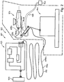
- FIG. 2 is a schematic view of a second embodiment of a compressed gas processing system 901 for compressed gas operated paint shops 902 shown.
- a supply station 921 and a compressed gas source 923 which feeds this, reference is made to the statements relating to that in US Pat FIG. 1 referenced first embodiment shown.
- a spray head 914 is used, which is connected to only one supply line 910.
- the spray head 914 is arranged on a first arm 944a of a manipulator 944 and is moved by the latter during painting according to the requirements.
- An ionizer 913 is in the vicinity of the spray head 914 on a second arm 944b of the manipulator 944, so that a second supply line section 910b with a length A910b is sufficiently long in all positions of the manipulator 944 to allow the spray head 914 and the ionizer 913 without restriction of freedom of movement connect.
- a first supply line section 910a which connects the supply device 921 to the ionization device 913, has a length A910a corresponding to the requirements and ensures by its length that the manipulator 944 can move without restriction in a painting room 945.
- the ionization device 913 includes a high voltage generator 940 and is connected thereto via a multi-wire line 938. According to an embodiment variant, not shown, the line 938 is guided parallel to the first supply line section 910a.
- FIG. 3 a second ionization device 101 is shown in a sectional view.
- the ionization device 101 is used like those in the FIGS. 1 and 2 shown first ionization devices.
- the ionization device 101 comprises a container 102, which has a discharge chamber 103, wherein the discharge chamber 103 is flowed through by compressed gas 104.
- the ionization device 101 comprises two ionization bars 105, 106, which form high-voltage discharge devices 107, 108.
- the ionization bars 105, 106 can each be inserted into the container 102 through a third and a fourth connection 109, 110 such that these sections 111, 112 form a lateral surface 113 of the discharge chamber 103 and thus directly with the compressed gas flowing through the discharge chambers 103 in the flow direction s 104 come into contact.
- the ionizing bars 105, 106 are connected via multi-wire lines, not shown, with a high voltage generator, not shown.
- First and second ports 114, 115 are first and second supply pipe sections of a supply line (not shown) connected. Electrodes 116, 117 of the ionizing rods 105, 106 are in direct contact with the compressed gas 104.
- FIG. 4 a third ionization device 201 is shown in a sectional view.
- the ionization device 201 is used like those in the FIGS. 1 and 2 shown first ionization devices.
- the ionization device 201 comprises a container 202, which has a discharge chamber 203, wherein the discharge chamber 203 is flowed through by the compressed gas 204.
- the ionization device 201 comprises different from that in the FIG. 3 shown ionization device only one Ionticiansstab 205, which forms a high voltage discharge device 207.
- the ionization rod 205 can be inserted into the container 202 by a third connection 209 in such a way that it forms a section 211 of a lateral surface 213 of the discharge chamber 203 and thus comes into direct contact with the compressed gas 204 flowing through the discharge chambers 203 in the flow direction s.
- the ionizing rod 205 is connected via a multicore cable, not shown, with a high voltage generator, not shown.
- Connected to first and second ports 214, 215 are first and second supply line sections of a supply line (not shown). Electrodes 216 of the ionization rod 205 are in direct contact with the pressurized gas 204.
- FIG. 5 is shown as a third embodiment, a compressed gas processing system 401, in which for supplying an explosion-proof paint shop 402b Ionticians wornen 412 and 413, with all its components, namely an ionizing rod 429 and 430, a discharge chamber 427 and 428 and a high voltage generator 439 and 440 within a explosion-proof room or Rb are arranged, in which a guided by a manipulator 444 spray head 414 is located.
- an explosion-proof paint shop 402b Ionmaschines wornen 412 and 413 with all its components, namely an ionizing rod 429 and 430, a discharge chamber 427 and 428 and a high voltage generator 439 and 440 within a explosion-proof room or Rb are arranged, in which a guided by a manipulator 444 spray head 414 is located.
- FIG. 6 is a fourth embodiment variant Druckgasaufkungssystem 501 shown, which analogous to that in the FIG. 1 constructed in the first embodiment, wherein in the fifth embodiment, a spray head 514 is guided by a manipulator 544.
- a compressed gas processing system 601 which is intended for operation in an explosion-proof room Rb, with ionizing 612 and 613 with their components Iontechnischsstab 629 and 630 and discharge chamber 627 and 628 are within the explosion-proof room Rb and only their high voltage generators 639 and 640 are arranged outside the explosion-proof room Rb.
- container 625, 626 in which the ionizing rods and the discharge chambers are installed, arranged on a fixed base 647 of a manipulator 644, from which a spray head 614 is guided.
- FIG. 8 6 shows a compressed gas treatment system 701 which is suitable for operation in an explosion-proof room Rb, with ionization devices 712 and 713 with their ionizing bar 729, 730 and discharge chamber 727, 728 components inside the explosion-proof room Rb and only their high-voltage generators 739, 740 outside the explosion-proof room Rb are arranged.
- containers 725, 726 in which the ionizing rods 729 and 730 and discharge chambers 727 and 728 are installed, in contrast to that in the FIG. 9 shown embodiment, arranged on an arm 744b of a manipulator 744, from which a spray head 714 is guided.
- a pressurized gas treatment system 801 is shown, which is suitable for operation in an explosion-proof room Rb, with ionizing devices 812 and 813 with all their components, namely an ionizing bar 829 or 830, a discharge chamber 827 or 828 and a high voltage generator 839 and 839, respectively 840 within the explosion-proof room Rb.
- containers 825 and 826 in which the ionizing rods 829 and 830 and discharge chambers 827 and 828 are installed, are arranged on an arm 844b of a manipulator 844, from which a spray head 814 is guided.
- the high-voltage generators 839, 840 are connected via electrical cables or multicore cables 837, 838 to the ionizing rods 829, 830 and are arranged stationarily in the explosion-proof room Rb.
Landscapes
- Engineering & Computer Science (AREA)
- Robotics (AREA)
- Electrostatic Spraying Apparatus (AREA)
- Nozzles (AREA)
- Details Or Accessories Of Spraying Plant Or Apparatus (AREA)
Claims (13)
- Système de traitement de gaz comprimé (1; 301; 401; 501; 601; 701; 801; 901) pour des installations de revêtement actionnées par un gaz comprimé, comprenant- une source de gaz comprimé (23; 923),- une station d'alimentation (21; 321; 921), qui est alimentée en gaz comprimé (4; 104; 204) à partir de la source de gaz comprimé (23; 923),- au moins une tête de pulvérisation (14; 314; 346; 414; 514; 614; 714; 814; 914),- au moins un dispositif à haute tension, en particulier un dispositif d'ionisation (12, 13; 101; 201; 312; 313; 412; 413; 612; 613; 712; 713; 812; 813; 913),- dans lequel le dispositif à haute tension, en particulier le dispositif d'ionisation (12, 13; 101; 201; 312; 313; 412; 413; 612; 613; 712; 713; 812; 813; 913) comprend une chambre de décharge (27, 28; 427, 428; 727, 728; 827, 828), un dispositif de décharge à haute tension (17, 18; 107, 108; 207) et un générateur de haute tension (39, 40; 439, 440; 639, 640; 739, 740; 839, 840),- dans lequel le dispositif à haute tension, en particulier le dispositif d'ionisation (12, 13; 101; 201; 312; 313; 412; 413; 612; 613; 712; 713; 812; 813; 913) est disposé à l'extérieur de la station d'alimentation (21; 321; 921), et- dans lequel le dispositif à haute tension, en particulier le dispositif d'ionisation (12, 13; 101; 201; 312; 313; 412; 413; 612; 613; 712; 713; 812; 813; 913) est installé en aval de la station d'alimentation (21; 321; 921) dans le courant du gaz comprimé (4; 104; 204),caractérisé en ce que- pour l'utilisation du système de traitement de gaz comprimé (1; 301; 401; 501; 601; 701; 801; 901) dans une chambre de laquage protégée contre l'explosion (Rb) de l'installation de revêtement la chambre de décharge (27, 28; 427, 428; 727, 728; 827, 828) et le dispositif de décharge à haute tension (17, 18; 107, 108; 207) du dispositif à haute tension, en particulier du dispositif d'ionisation (12, 13; 101; 201; 312; 313; 412; 413; 612; 613; 712; 713; 812; 813; 913) sont disposés à l'intérieur de la chambre de laquage protégée contre l'explosion (Rb).
- Système de traitement de gaz comprimé (1; 301; 401; 501; 601; 701; 801; 901) selon la revendication 1, caractérisé en ce que- pour l'utilisation du système de traitement de gaz comprimé (1; 301; 401; 501; 601; 701; 801; 901) dans une chambre de laquage protégée contre l'explosion (Rb) de l'installation de revêtement le générateur de haute tension (39, 40; 439, 440; 639, 640; 739, 740; 839, 840) du dispositif à haute tension, en particulier du dispositif d'ionisation (12, 13; 101; 201; 312; 313; 412; 413; 612; 613; 712; 713; 812; 813; 913) est disposé à l'extérieur de la chambre de laquage protégée contre l'explosion (Rb),- dans lequel le générateur de haute tension (39, 40; 439, 440; 639, 640; 739, 740; 839, 840) est relié par des câbles électriques (37, 38; 439, 440; 639, 640; 739, 740; 839, 840) au dispositif de décharge à haute tension (17, 18; 107, 108; 207).
- Système de traitement de gaz comprimé (1; 301; 401; 501; 601; 701; 801; 901) (1) selon la revendication 1, caractérisé en ce que pour l'utilisation du système de traitement de gaz comprimé (1; 301; 401; 501; 601; 701; 801; 901) dans une chambre de laquage protégée contre l'explosion (Rb) le générateur de haute tension (39, 40; 439, 440; 639, 640; 739, 740; 839, 840) du dispositif à haute tension, en particulier du dispositif d'ionisation (12, 13; 101; 201; 312; 313; 412; 413; 612; 613; 712; 713; 812; 813; 913) est disposé à l'intérieur de la chambre de laquage protégée contre l'explosion (Rb), dans lequel le générateur de haute tension (39, 40; 439, 440; 639, 940; 739, 740; 839, 840) est réalisé sous la forme d'un générateur de haute tension (39, 40; 439, 440; 639, 940; 739, 740; 839, 840) protégé contre l'explosion.
- Système de traitement de gaz comprimé (1; 301; 401; 501; 601; 701; 801; 901) selon la revendication 2 ou 3, caractérisé en ce que la chambre de décharge (27, 28; 427, 428; 727, 728; 827, 828) et le dispositif de décharge à haute tension (17, 18; 107, 108; 207) forment un module ou en ce que la chambre de décharge (27, 28; 427, 428; 727, 728; 827, 828) et le dispositif de décharge à haute tension (17, 18; 107, 108; 207) et le générateur de haute tension (39, 40; 439, 440; 639, 640; 739, 740; 839, 840) forment un module, dans lequel le module respectivement formé- est intégré dans la tête de pulvérisation (14; 314; 346; 414; 514; 614; 714; 814; 914) ou- est disposé dans un manipulateur (44; 444; 544; 644; 744; 844; 944), au moyen duquel la tête de pulvérisation (14; 314; 346; 414; 514; 614; 714; 814; 914) est guidée,- dans lequel le module, lorsqu'il est disposé sur le manipulateur (44; 444; 544; 644; 744; 844; 944), est disposé en particulier sur un composant déplacé en fonctionnement, en particulier sur un bras (44a, 44b; 744b; 844b; 944a, 944b) du manipulateur (44; 444; 544; 644; 744; 844; 944) ou il est disposé de façon stationnaire dans la chambre de laquage protégée contre l'explosion (Rb).
- Système de traitement de gaz comprimé (1; 301; 401; 501; 601; 701; 801; 901) selon l'une quelconque des revendications précédentes, caractérisé en ce que- un dispositif de filtrage (3) et/ou un dispositif de chauffage (24) est ou sont monté(s) en amont du dispositif à haute tension, en particulier du dispositif d'ionisation (12, 13; 101; 201; 312; 313; 412; 413; 612; 613; 712; 713; 812; 813; 913),- dans lequel le dispositif de filtrage (3) et/ou le dispositif de chauffage (24) est ou sont disposé(s) à l'extérieur de la chambre de laquage protégée contre l'explosion (Rb) et en particulier dans la station d'alimentation (21; 321; 921), ou- dans lequel le dispositif de filtrage (3) et/ou le dispositif de chauffage (24) est ou sont disposé(s) à l'intérieur de la chambre de laquage protégée contre l'explosion (Rb) et à l'extérieur de la station d'alimentation (21; 321; 921).
- Système de traitement de gaz comprimé (1; 301; 401; 501; 601; 701; 801; 901) selon la revendication 1, caractérisé en ce que- l'installation de revêtement destinée à l'utilisation du système de traitement de gaz comprimé (1; 301; 401; 501; 601;701; 801; 901) est configurée comme une installation de laquage humide (302a) ou comme une installation de revêtement à la poudre (302b) avec une chambre de laquage humide ou une chambre de revêtement,- dans lequel soit la chambre de décharge (27, 28; 427, 428; 727, 728; 827, 828), le dispositif de décharge à haute tension (17, 18; 107, 108; 207) et le générateur de haute tension (39, 40; 439, 440; 639, 640; 739, 740; 839, 840) du dispositif à haute tension, en particulier du dispositif d'ionisation (12, 13; 101; 201; 312; 313; 412; 413; 612; 613; 712; 713; 812; 813; 913) forment un module commun ou- dans lequel la chambre de décharge (27, 28; 427, 428; 727, 728; 827, 828) et le dispositif de décharge haute tension (17, 18; 107, 108; 207) forment un module commun,- dans lequel le module formé est disposé dans la chambre de laquage ou la chambre de revêtement, de telle manière que ce module- ou bien soit raccordé par une première partie de conduite d'alimentation (9a, 10a) à la station d'alimentation (21; 321; 921) et par une deuxième partie de conduite d'alimentation (9b, 10b) à la tête de pulvérisation (14; 314; 346; 414; 514; 614; 714; 814; 914)- ou bien que le module formé soit intégré dans la tête de pulvérisation (14; 314, 346; 414; 514; 614; 714; 814; 914).
- Système de traitement de gaz comprimé (1; 301; 401; 501; 601; 701; 801; 901) selon la revendication 6, caractérisé en ce que- soit le module formé est disposé sur un manipulateur (44; 444; 544; 644; 744; 844; 944) par lequel la tête de pulvérisation (14; 314; 346; 414; 514; 614; 714; 814; 914) est guidée, dans lequel le module, lorsqu'il est disposé sur le manipulateur (44; 444; 544; 644; 744; 844; 944), est disposé en particulier sur un composant déplacé en fonctionnement, en particulier sur un bras (44a, 44b; 744b; 844b; 944a, 944b) du manipulateur (44; 444; 544; 644; 744; 844; 944)- soit le module formé est disposé de façon stationnaire dans la chambre de laquage ou la chambre de revêtement.
- Système de traitement de gaz comprimé (1; 301; 401; 501; 601; 701; 801; 901) selon la revendication 6 ou 7, caractérisé en ce que- un dispositif de filtrage (3) et/ou un dispositif de chauffage (24) est ou sont monté(s) en amont du dispositif à haute tension, en particulier du dispositif d'ionisation (12, 13; 101; 201; 312; 313; 412; 413; 612; 613; 712; 713; 812; 813; 913), dans lequel le dispositif de filtrage (3) et/ou le dispositif de chauffage (24)- soit est ou sont disposé(s) dans la station d'alimentation (21; 321; 921)- soit est ou sont disposé (s) entre la station d'alimentation (21; 321; 921) et le dispositif d'ionisation (12, 13; 101; 201; 312; 313; 412; 413; 612; 613; 712; 713; 812; 813; 913).
- Système de traitement de gaz comprimé (1; 301; 401; 501; 601; 701; 801; 901) selon l'une quelconque des revendications précédentes, caractérisé en ce que la partie de conduite d'alimentation (9b, 10b), qui relie le dispositif à haute tension, en particulier le dispositif d'ionisation (12, 13; 101; 201; 312; 313; 412; 413; 612; 613; 712; 713; 812; 813; 913) et la tête de pulvérisation (14; 314; 346; 414; 514; 614; 714; 814; 914) présente une longueur (A9b, A10b; A910a, A910b) au maximum de 2, 5 m et en particulier au maximum de 0,5 m et dans lequel cette partie de conduite d'alimentation (9b, 10b; 910b) est en particulier, dans son canal d'écoulement, libre d'éléments métalliques comme notamment des soupapes et/ou des réducteurs de pression.
- Système de traitement de gaz comprimé selon au moins une des revendications précédentes, caractérisé en ce que l'on utilise au choix comme gaz comprimé de l'air ou de l'azote ou un mélange azote-air.
- Installation de revêtement actionnée par un gaz comprimé telle qu'une installation de laquage comprenant une chambre de laquage protégée contre l'explosion (Rb), une source de gaz comprimé (23; 923) et au moins une tête de pulvérisation (314; 346), caractérisée en ce que l'installation de revêtement comprend un système de traitement de gaz comprimé (1; 301; 401; 501; 601; 701; 801; 901) selon la revendication 1 et en outre en particulier selon au moins une des revendications 2 à 5 ou 10.
- Installation de revêtement actionnée par un gaz comprimé comme une installation de laquage humide ou une installation de revêtement à la poudre comprenant une chambre de laquage humide ou une chambre de revêtement, une source de gaz comprimé (223) et au moins une tête de pulvérisation (314; 346), caractérisée en ce que l'installation de revêtement comprend un système de traitement de gaz comprimé (301) selon la revendication 6 et en outre en particulier selon au moins une des revendications 7 à 10.
- Système de traitement de gaz comprimé selon l'une quelconque des revendications 1 à 10, caractérisé en ce que soit le dispositif à haute tension, en particulier le dispositif d'ionisation (12, 13; 312, 313; 913) est raccordé par une première partie de conduite d'alimentation (9a, 10a; 309a; 910a) à la station d'alimentation (21; 321; 921) et par une deuxième partie de conduite d'alimentation (9b, 10b; 309b; 910b) à la tête de pulvérisation (14; 314; 346; 914) soit le dispositif à haute tension, en particulier le dispositif d'ionisation est intégré dans la tête de pulvérisation et est raccordé par la conduite d'alimentation à la station d'alimentation.
Applications Claiming Priority (2)
| Application Number | Priority Date | Filing Date | Title |
|---|---|---|---|
| DE202012012185.5U DE202012012185U1 (de) | 2012-12-20 | 2012-12-20 | Druckgasaufbereitungssystem für druckgasbetriebene Beschichtungsanlagen und druckgasbetriebene Beschichtungsanlage |
| PCT/EP2013/003896 WO2014095081A2 (fr) | 2012-12-20 | 2013-12-20 | Système de préparation de gaz comprimé pour des installations de revêtement à gaz comprimé et installations de revêtement à gaz comprimé |
Publications (2)
| Publication Number | Publication Date |
|---|---|
| EP2934725A2 EP2934725A2 (fr) | 2015-10-28 |
| EP2934725B1 true EP2934725B1 (fr) | 2018-08-08 |
Family
ID=50071566
Family Applications (1)
| Application Number | Title | Priority Date | Filing Date |
|---|---|---|---|
| EP13828912.9A Active EP2934725B1 (fr) | 2012-12-20 | 2013-12-20 | Système de traitement de gaz comprimé et installation de revêtement actionnée par un gaz comprimé |
Country Status (6)
| Country | Link |
|---|---|
| US (1) | US20150352567A1 (fr) |
| EP (1) | EP2934725B1 (fr) |
| CN (1) | CN105228727B (fr) |
| DE (1) | DE202012012185U1 (fr) |
| MX (1) | MX351019B (fr) |
| WO (1) | WO2014095081A2 (fr) |
Families Citing this family (6)
| Publication number | Priority date | Publication date | Assignee | Title |
|---|---|---|---|---|
| ITFI20130286A1 (it) * | 2013-11-25 | 2015-05-26 | Eurosider Sas Di Milli Ottavio & C | Apparato automatico di verniciatura pneumatica. |
| EP2933024A1 (fr) * | 2014-04-14 | 2015-10-21 | Luciano Simonato | Installation de peinture par pulvérisation |
| GB2553787A (en) * | 2016-09-13 | 2018-03-21 | Haydell Michael | A conditioning apparatus for providing a carrier gas |
| WO2019020796A2 (fr) * | 2017-07-28 | 2019-01-31 | Thomas Mayer | Dispositif pour utiliser un gaz sous pression sur un dispositif de pulvérisation fonctionnant avec un gaz sous pression, procédé pour utiliser un gaz sous pression sur un dispositif de pulvérisation fonctionnant avec un gaz sous pression ainsi que procédé pour la pulvérisation d'un milieu liquide |
| CN110506973A (zh) * | 2019-10-14 | 2019-11-29 | 中国烟草总公司郑州烟草研究院 | 一种向造纸法再造烟叶中施加烟粉的方法 |
| CN110679992B (zh) * | 2019-10-14 | 2021-08-17 | 河南卷烟工业烟草薄片有限公司 | 一种烟粉喷送分散特性的测量系统及测量方法 |
Family Cites Families (9)
| Publication number | Priority date | Publication date | Assignee | Title |
|---|---|---|---|---|
| US3017119A (en) * | 1955-09-13 | 1962-01-16 | Air Reduction | Apparatus for metal spraying |
| US2890388A (en) * | 1955-11-30 | 1959-06-09 | Gen Motors Corp | Electrostatic spray charger |
| GB863190A (en) * | 1958-06-30 | 1961-03-15 | Metco Inc | Heat-fusible material spray gun and method for coating a surface with a heat-fusiblematerial |
| CN86200692U (zh) * | 1986-02-04 | 1987-09-12 | 刘国栋 | 喷涂离子化附加器 |
| EP0437383A1 (fr) * | 1990-01-12 | 1991-07-17 | Regie Nationale Des Usines Renault S.A. | Procédé et dispositif de peinture électrostatique sur pièces plastiques |
| PT1242779E (pt) * | 1999-04-21 | 2005-08-31 | Junair Group Ltd | Sistema de secagem de pintura |
| WO2009056950A1 (fr) * | 2007-10-31 | 2009-05-07 | Eurosider Sas | Dispositif de peinture par pulvérisation à ionisation du fluide porteur |
| CN101928994B (zh) * | 2010-07-13 | 2014-07-23 | 三河厚德光机电有限公司 | 一种恒温喷丝板及其制造方法 |
| DE102011011054B4 (de) | 2011-02-11 | 2023-01-26 | Thomas Mayer | Verfahren zur Aufbereitung von Druckluft sowie Vorrichtung zur Aufbereitung von Druckluft |
-
2012
- 2012-12-20 DE DE202012012185.5U patent/DE202012012185U1/de not_active Expired - Lifetime
-
2013
- 2013-12-20 MX MX2015007964A patent/MX351019B/es active IP Right Grant
- 2013-12-20 EP EP13828912.9A patent/EP2934725B1/fr active Active
- 2013-12-20 WO PCT/EP2013/003896 patent/WO2014095081A2/fr not_active Ceased
- 2013-12-20 CN CN201380073483.1A patent/CN105228727B/zh not_active Expired - Fee Related
-
2015
- 2015-06-16 US US14/740,591 patent/US20150352567A1/en not_active Abandoned
Non-Patent Citations (1)
| Title |
|---|
| None * |
Also Published As
| Publication number | Publication date |
|---|---|
| EP2934725A2 (fr) | 2015-10-28 |
| CN105228727B (zh) | 2018-11-13 |
| US20150352567A1 (en) | 2015-12-10 |
| WO2014095081A3 (fr) | 2014-08-14 |
| CN105228727A (zh) | 2016-01-06 |
| WO2014095081A2 (fr) | 2014-06-26 |
| DE202012012185U1 (de) | 2014-04-30 |
| MX351019B (es) | 2017-09-28 |
| MX2015007964A (es) | 2016-03-16 |
Similar Documents
| Publication | Publication Date | Title |
|---|---|---|
| EP2934725A2 (fr) | Système de préparation de gaz comprimé pour des installations de revêtement à gaz comprimé et installations de revêtement à gaz comprimé | |
| DE2905223C2 (fr) | ||
| EP1690601B1 (fr) | Dispositif de revêtement thermique | |
| DE3014221A1 (de) | Verfahren und vorrichtung zum elektrostatischen spritzen | |
| DE102014016364A1 (de) | Reinigungsverfahren und Reinigungsvorrichtung für ein oder mehrere Teile eines Applikationssystems | |
| DE102009045200A1 (de) | Verfahren und Vorrichtung zum Bearbeiten von Bauteilen elektrischer Maschinen | |
| DE3601437C2 (de) | Elektrischer Roboter zur Verwendung in Gefahrenzonen | |
| EP1859872B1 (fr) | Bloc changeur de produit de revêtement | |
| DE1900821A1 (de) | Elektrostatische Spruehpistole | |
| DE102017101370A1 (de) | Vorrichtung zum Vernebeln einer Spülflüssigkeit | |
| DE102011106134B4 (de) | Vorrichtung und Verfahren zum Spülen von Kunststoffbehältnissen | |
| DE102015110312B4 (de) | Pulverweiche und Pulverabgabesystem mit Pulverweiche | |
| DE102011011054B4 (de) | Verfahren zur Aufbereitung von Druckluft sowie Vorrichtung zur Aufbereitung von Druckluft | |
| DE3712469A1 (de) | System zum unterdruecken eines zuendfunkens und von feuer an einem elektrostatischen sprueher | |
| EP1889666B1 (fr) | Dispositif destiné à recouvrir, en particulier pur laquer, des objets, en particulier de véhicules automobiles | |
| DE102019130920A1 (de) | Farbversorgungssystem für eine Beschichtungsanlage und zugehöriges Betriebsverfahren | |
| DE2038194A1 (de) | Elektrostatische Spritzpistole | |
| DE19648999C2 (de) | Vorrichtung zur Reinigung, Beschichtung und/oder Aktivierung von Kunststoffoberflächen | |
| DE2555547C3 (de) | Vorrichtung zum elektrostatischen Auftragen bzw. Aufsprühen von Materialteilchen | |
| EP4501415A2 (fr) | Système d'alimentation en gaz de peinture, installation de peinture et procédé de fonctionnement d'une installation de peinture | |
| DE102015213422A1 (de) | Roboterwerkzeug und Roboter zur Abgabe eines Korrosionsschutzwachses und Verfahren hierzu | |
| DE102015111861B3 (de) | Vorrichtung zum Kühlen oder Schmieren von spanabhebenden Werkzeugen und/oder von Werkstücken | |
| DE10321614A1 (de) | Beschichtungsverfahren sowie Pulverdüse und Beschichtungskabine | |
| DE102019126651A1 (de) | Lichtbogenbrenner und Lichtbogen-Drahtspritzeinrichtung | |
| DE102009046410A1 (de) | Vorrichtung zum induktiven Heizen von Werkstücken mit Kühlung |
Legal Events
| Date | Code | Title | Description |
|---|---|---|---|
| PUAI | Public reference made under article 153(3) epc to a published international application that has entered the european phase |
Free format text: ORIGINAL CODE: 0009012 |
|
| 17P | Request for examination filed |
Effective date: 20150617 |
|
| AK | Designated contracting states |
Kind code of ref document: A2 Designated state(s): AL AT BE BG CH CY CZ DE DK EE ES FI FR GB GR HR HU IE IS IT LI LT LU LV MC MK MT NL NO PL PT RO RS SE SI SK SM TR |
|
| AX | Request for extension of the european patent |
Extension state: BA ME |
|
| DAX | Request for extension of the european patent (deleted) | ||
| STAA | Information on the status of an ep patent application or granted ep patent |
Free format text: STATUS: EXAMINATION IS IN PROGRESS |
|
| 17Q | First examination report despatched |
Effective date: 20170419 |
|
| REG | Reference to a national code |
Ref country code: DE Ref legal event code: R079 Ref document number: 502013010825 Country of ref document: DE Free format text: PREVIOUS MAIN CLASS: B01D0053320000 Ipc: B05B0007240000 |
|
| RIC1 | Information provided on ipc code assigned before grant |
Ipc: B05B 5/16 20060101ALI20180122BHEP Ipc: B05B 13/04 20060101ALI20180122BHEP Ipc: B05B 5/03 20060101ALI20180122BHEP Ipc: B05B 15/00 20180101ALN20180122BHEP Ipc: B05B 7/24 20060101AFI20180122BHEP Ipc: B05B 7/08 20060101ALI20180122BHEP |
|
| GRAP | Despatch of communication of intention to grant a patent |
Free format text: ORIGINAL CODE: EPIDOSNIGR1 |
|
| STAA | Information on the status of an ep patent application or granted ep patent |
Free format text: STATUS: GRANT OF PATENT IS INTENDED |
|
| INTG | Intention to grant announced |
Effective date: 20180322 |
|
| GRAS | Grant fee paid |
Free format text: ORIGINAL CODE: EPIDOSNIGR3 |
|
| GRAA | (expected) grant |
Free format text: ORIGINAL CODE: 0009210 |
|
| STAA | Information on the status of an ep patent application or granted ep patent |
Free format text: STATUS: THE PATENT HAS BEEN GRANTED |
|
| AK | Designated contracting states |
Kind code of ref document: B1 Designated state(s): AL AT BE BG CH CY CZ DE DK EE ES FI FR GB GR HR HU IE IS IT LI LT LU LV MC MK MT NL NO PL PT RO RS SE SI SK SM TR |
|
| REG | Reference to a national code |
Ref country code: GB Ref legal event code: FG4D Free format text: NOT ENGLISH |
|
| REG | Reference to a national code |
Ref country code: CH Ref legal event code: EP Ref country code: AT Ref legal event code: REF Ref document number: 1026389 Country of ref document: AT Kind code of ref document: T Effective date: 20180815 |
|
| REG | Reference to a national code |
Ref country code: IE Ref legal event code: FG4D Free format text: LANGUAGE OF EP DOCUMENT: GERMAN |
|
| REG | Reference to a national code |
Ref country code: DE Ref legal event code: R096 Ref document number: 502013010825 Country of ref document: DE |
|
| REG | Reference to a national code |
Ref country code: NL Ref legal event code: MP Effective date: 20180808 |
|
| REG | Reference to a national code |
Ref country code: LT Ref legal event code: MG4D |
|
| PG25 | Lapsed in a contracting state [announced via postgrant information from national office to epo] |
Ref country code: NO Free format text: LAPSE BECAUSE OF FAILURE TO SUBMIT A TRANSLATION OF THE DESCRIPTION OR TO PAY THE FEE WITHIN THE PRESCRIBED TIME-LIMIT Effective date: 20181108 Ref country code: SE Free format text: LAPSE BECAUSE OF FAILURE TO SUBMIT A TRANSLATION OF THE DESCRIPTION OR TO PAY THE FEE WITHIN THE PRESCRIBED TIME-LIMIT Effective date: 20180808 Ref country code: BG Free format text: LAPSE BECAUSE OF FAILURE TO SUBMIT A TRANSLATION OF THE DESCRIPTION OR TO PAY THE FEE WITHIN THE PRESCRIBED TIME-LIMIT Effective date: 20181108 Ref country code: NL Free format text: LAPSE BECAUSE OF FAILURE TO SUBMIT A TRANSLATION OF THE DESCRIPTION OR TO PAY THE FEE WITHIN THE PRESCRIBED TIME-LIMIT Effective date: 20180808 Ref country code: IS Free format text: LAPSE BECAUSE OF FAILURE TO SUBMIT A TRANSLATION OF THE DESCRIPTION OR TO PAY THE FEE WITHIN THE PRESCRIBED TIME-LIMIT Effective date: 20181208 Ref country code: FI Free format text: LAPSE BECAUSE OF FAILURE TO SUBMIT A TRANSLATION OF THE DESCRIPTION OR TO PAY THE FEE WITHIN THE PRESCRIBED TIME-LIMIT Effective date: 20180808 Ref country code: GR Free format text: LAPSE BECAUSE OF FAILURE TO SUBMIT A TRANSLATION OF THE DESCRIPTION OR TO PAY THE FEE WITHIN THE PRESCRIBED TIME-LIMIT Effective date: 20181109 Ref country code: RS Free format text: LAPSE BECAUSE OF FAILURE TO SUBMIT A TRANSLATION OF THE DESCRIPTION OR TO PAY THE FEE WITHIN THE PRESCRIBED TIME-LIMIT Effective date: 20180808 Ref country code: LT Free format text: LAPSE BECAUSE OF FAILURE TO SUBMIT A TRANSLATION OF THE DESCRIPTION OR TO PAY THE FEE WITHIN THE PRESCRIBED TIME-LIMIT Effective date: 20180808 Ref country code: PL Free format text: LAPSE BECAUSE OF FAILURE TO SUBMIT A TRANSLATION OF THE DESCRIPTION OR TO PAY THE FEE WITHIN THE PRESCRIBED TIME-LIMIT Effective date: 20180808 |
|
| PG25 | Lapsed in a contracting state [announced via postgrant information from national office to epo] |
Ref country code: HR Free format text: LAPSE BECAUSE OF FAILURE TO SUBMIT A TRANSLATION OF THE DESCRIPTION OR TO PAY THE FEE WITHIN THE PRESCRIBED TIME-LIMIT Effective date: 20180808 Ref country code: AL Free format text: LAPSE BECAUSE OF FAILURE TO SUBMIT A TRANSLATION OF THE DESCRIPTION OR TO PAY THE FEE WITHIN THE PRESCRIBED TIME-LIMIT Effective date: 20180808 Ref country code: LV Free format text: LAPSE BECAUSE OF FAILURE TO SUBMIT A TRANSLATION OF THE DESCRIPTION OR TO PAY THE FEE WITHIN THE PRESCRIBED TIME-LIMIT Effective date: 20180808 |
|
| PG25 | Lapsed in a contracting state [announced via postgrant information from national office to epo] |
Ref country code: RO Free format text: LAPSE BECAUSE OF FAILURE TO SUBMIT A TRANSLATION OF THE DESCRIPTION OR TO PAY THE FEE WITHIN THE PRESCRIBED TIME-LIMIT Effective date: 20180808 Ref country code: ES Free format text: LAPSE BECAUSE OF FAILURE TO SUBMIT A TRANSLATION OF THE DESCRIPTION OR TO PAY THE FEE WITHIN THE PRESCRIBED TIME-LIMIT Effective date: 20180808 Ref country code: EE Free format text: LAPSE BECAUSE OF FAILURE TO SUBMIT A TRANSLATION OF THE DESCRIPTION OR TO PAY THE FEE WITHIN THE PRESCRIBED TIME-LIMIT Effective date: 20180808 Ref country code: IT Free format text: LAPSE BECAUSE OF FAILURE TO SUBMIT A TRANSLATION OF THE DESCRIPTION OR TO PAY THE FEE WITHIN THE PRESCRIBED TIME-LIMIT Effective date: 20180808 |
|
| REG | Reference to a national code |
Ref country code: DE Ref legal event code: R097 Ref document number: 502013010825 Country of ref document: DE |
|
| PG25 | Lapsed in a contracting state [announced via postgrant information from national office to epo] |
Ref country code: SK Free format text: LAPSE BECAUSE OF FAILURE TO SUBMIT A TRANSLATION OF THE DESCRIPTION OR TO PAY THE FEE WITHIN THE PRESCRIBED TIME-LIMIT Effective date: 20180808 Ref country code: SM Free format text: LAPSE BECAUSE OF FAILURE TO SUBMIT A TRANSLATION OF THE DESCRIPTION OR TO PAY THE FEE WITHIN THE PRESCRIBED TIME-LIMIT Effective date: 20180808 Ref country code: DK Free format text: LAPSE BECAUSE OF FAILURE TO SUBMIT A TRANSLATION OF THE DESCRIPTION OR TO PAY THE FEE WITHIN THE PRESCRIBED TIME-LIMIT Effective date: 20180808 |
|
| PLBE | No opposition filed within time limit |
Free format text: ORIGINAL CODE: 0009261 |
|
| STAA | Information on the status of an ep patent application or granted ep patent |
Free format text: STATUS: NO OPPOSITION FILED WITHIN TIME LIMIT |
|
| 26N | No opposition filed |
Effective date: 20190509 |
|
| REG | Reference to a national code |
Ref country code: CH Ref legal event code: PL |
|
| PG25 | Lapsed in a contracting state [announced via postgrant information from national office to epo] |
Ref country code: MC Free format text: LAPSE BECAUSE OF FAILURE TO SUBMIT A TRANSLATION OF THE DESCRIPTION OR TO PAY THE FEE WITHIN THE PRESCRIBED TIME-LIMIT Effective date: 20180808 Ref country code: SI Free format text: LAPSE BECAUSE OF FAILURE TO SUBMIT A TRANSLATION OF THE DESCRIPTION OR TO PAY THE FEE WITHIN THE PRESCRIBED TIME-LIMIT Effective date: 20180808 Ref country code: LU Free format text: LAPSE BECAUSE OF NON-PAYMENT OF DUE FEES Effective date: 20181220 |
|
| REG | Reference to a national code |
Ref country code: IE Ref legal event code: MM4A |
|
| REG | Reference to a national code |
Ref country code: BE Ref legal event code: MM Effective date: 20181231 |
|
| PG25 | Lapsed in a contracting state [announced via postgrant information from national office to epo] |
Ref country code: IE Free format text: LAPSE BECAUSE OF NON-PAYMENT OF DUE FEES Effective date: 20181220 |
|
| PG25 | Lapsed in a contracting state [announced via postgrant information from national office to epo] |
Ref country code: BE Free format text: LAPSE BECAUSE OF NON-PAYMENT OF DUE FEES Effective date: 20181231 |
|
| PG25 | Lapsed in a contracting state [announced via postgrant information from national office to epo] |
Ref country code: LI Free format text: LAPSE BECAUSE OF NON-PAYMENT OF DUE FEES Effective date: 20181231 Ref country code: CH Free format text: LAPSE BECAUSE OF NON-PAYMENT OF DUE FEES Effective date: 20181231 |
|
| PG25 | Lapsed in a contracting state [announced via postgrant information from national office to epo] |
Ref country code: MT Free format text: LAPSE BECAUSE OF FAILURE TO SUBMIT A TRANSLATION OF THE DESCRIPTION OR TO PAY THE FEE WITHIN THE PRESCRIBED TIME-LIMIT Effective date: 20180808 |
|
| PGFP | Annual fee paid to national office [announced via postgrant information from national office to epo] |
Ref country code: AT Payment date: 20191210 Year of fee payment: 7 |
|
| PG25 | Lapsed in a contracting state [announced via postgrant information from national office to epo] |
Ref country code: PT Free format text: LAPSE BECAUSE OF FAILURE TO SUBMIT A TRANSLATION OF THE DESCRIPTION OR TO PAY THE FEE WITHIN THE PRESCRIBED TIME-LIMIT Effective date: 20180808 |
|
| PG25 | Lapsed in a contracting state [announced via postgrant information from national office to epo] |
Ref country code: CY Free format text: LAPSE BECAUSE OF FAILURE TO SUBMIT A TRANSLATION OF THE DESCRIPTION OR TO PAY THE FEE WITHIN THE PRESCRIBED TIME-LIMIT Effective date: 20180808 Ref country code: HU Free format text: LAPSE BECAUSE OF FAILURE TO SUBMIT A TRANSLATION OF THE DESCRIPTION OR TO PAY THE FEE WITHIN THE PRESCRIBED TIME-LIMIT; INVALID AB INITIO Effective date: 20131220 Ref country code: MK Free format text: LAPSE BECAUSE OF NON-PAYMENT OF DUE FEES Effective date: 20180808 |
|
| REG | Reference to a national code |
Ref country code: AT Ref legal event code: MM01 Ref document number: 1026389 Country of ref document: AT Kind code of ref document: T Effective date: 20201220 |
|
| PG25 | Lapsed in a contracting state [announced via postgrant information from national office to epo] |
Ref country code: AT Free format text: LAPSE BECAUSE OF NON-PAYMENT OF DUE FEES Effective date: 20201220 |
|
| PG25 | Lapsed in a contracting state [announced via postgrant information from national office to epo] |
Ref country code: TR Free format text: LAPSE BECAUSE OF NON-PAYMENT OF DUE FEES Effective date: 20201220 |
|
| PGFP | Annual fee paid to national office [announced via postgrant information from national office to epo] |
Ref country code: GB Payment date: 20220629 Year of fee payment: 9 Ref country code: CZ Payment date: 20220620 Year of fee payment: 9 |
|
| PGFP | Annual fee paid to national office [announced via postgrant information from national office to epo] |
Ref country code: FR Payment date: 20220629 Year of fee payment: 9 |
|
| REG | Reference to a national code |
Ref country code: DE Ref legal event code: R082 Ref document number: 502013010825 Ref country code: DE Ref legal event code: R082 Ref document number: 502013010825 Country of ref document: DE Representative=s name: LORENZ & KOLLEGEN PATENTANWAELTE PARTNERSCHAFT, DE |
|
| PG25 | Lapsed in a contracting state [announced via postgrant information from national office to epo] |
Ref country code: CZ Free format text: LAPSE BECAUSE OF NON-PAYMENT OF DUE FEES Effective date: 20221220 |
|
| P01 | Opt-out of the competence of the unified patent court (upc) registered |
Effective date: 20230622 |
|
| REG | Reference to a national code |
Ref country code: DE Ref legal event code: R082 Ref document number: 502013010825 Country of ref document: DE Representative=s name: LORENZ & KOLLEGEN PATENTANWAELTE PARTNERSCHAFT, DE |
|
| GBPC | Gb: european patent ceased through non-payment of renewal fee |
Effective date: 20221220 |
|
| PG25 | Lapsed in a contracting state [announced via postgrant information from national office to epo] |
Ref country code: GB Free format text: LAPSE BECAUSE OF NON-PAYMENT OF DUE FEES Effective date: 20221220 |
|
| PG25 | Lapsed in a contracting state [announced via postgrant information from national office to epo] |
Ref country code: FR Free format text: LAPSE BECAUSE OF NON-PAYMENT OF DUE FEES Effective date: 20221231 |
|
| PGFP | Annual fee paid to national office [announced via postgrant information from national office to epo] |
Ref country code: DE Payment date: 20260629 Year of fee payment: 13 |