EP2934988B1 - Dispositif de liaison d'un berceau automobile - Google Patents
Dispositif de liaison d'un berceau automobile Download PDFInfo
- Publication number
- EP2934988B1 EP2934988B1 EP13779833.6A EP13779833A EP2934988B1 EP 2934988 B1 EP2934988 B1 EP 2934988B1 EP 13779833 A EP13779833 A EP 13779833A EP 2934988 B1 EP2934988 B1 EP 2934988B1
- Authority
- EP
- European Patent Office
- Prior art keywords
- cradle
- vehicle
- motor vehicle
- ear
- bearing
- Prior art date
- Legal status (The legal status is an assumption and is not a legal conclusion. Google has not performed a legal analysis and makes no representation as to the accuracy of the status listed.)
- Active
Links
Images

Classifications
-
- B—PERFORMING OPERATIONS; TRANSPORTING
- B60—VEHICLES IN GENERAL
- B60K—ARRANGEMENT OR MOUNTING OF PROPULSION UNITS OR OF TRANSMISSIONS IN VEHICLES; ARRANGEMENT OR MOUNTING OF PLURAL DIVERSE PRIME-MOVERS IN VEHICLES; AUXILIARY DRIVES FOR VEHICLES; INSTRUMENTATION OR DASHBOARDS FOR VEHICLES; ARRANGEMENTS IN CONNECTION WITH COOLING, AIR INTAKE, GAS EXHAUST OR FUEL SUPPLY OF PROPULSION UNITS IN VEHICLES
- B60K5/00—Arrangement or mounting of internal-combustion or jet-propulsion units
- B60K5/12—Arrangement of engine supports
- B60K5/1241—Link-type support
-
- B—PERFORMING OPERATIONS; TRANSPORTING
- B62—LAND VEHICLES FOR TRAVELLING OTHERWISE THAN ON RAILS
- B62D—MOTOR VEHICLES; TRAILERS
- B62D21/00—Understructures, i.e. chassis frame on which a vehicle body may be mounted
- B62D21/11—Understructures, i.e. chassis frame on which a vehicle body may be mounted with resilient means for suspension, e.g. of wheels or engine; sub-frames for mounting engine or suspensions
-
- B—PERFORMING OPERATIONS; TRANSPORTING
- B60—VEHICLES IN GENERAL
- B60G—VEHICLE SUSPENSION ARRANGEMENTS
- B60G21/00—Interconnection systems for two or more resiliently-suspended wheels, e.g. for stabilising a vehicle body with respect to acceleration, deceleration or centrifugal forces
- B60G21/02—Interconnection systems for two or more resiliently-suspended wheels, e.g. for stabilising a vehicle body with respect to acceleration, deceleration or centrifugal forces permanently interconnected
- B60G21/04—Interconnection systems for two or more resiliently-suspended wheels, e.g. for stabilising a vehicle body with respect to acceleration, deceleration or centrifugal forces permanently interconnected mechanically
- B60G21/05—Interconnection systems for two or more resiliently-suspended wheels, e.g. for stabilising a vehicle body with respect to acceleration, deceleration or centrifugal forces permanently interconnected mechanically between wheels on the same axle but on different sides of the vehicle, i.e. the left and right wheel suspensions being interconnected
- B60G21/055—Stabiliser bars
- B60G21/0551—Mounting means therefor
-
- B—PERFORMING OPERATIONS; TRANSPORTING
- B60—VEHICLES IN GENERAL
- B60G—VEHICLE SUSPENSION ARRANGEMENTS
- B60G2204/00—Indexing codes related to suspensions per se or to auxiliary parts
- B60G2204/10—Mounting of suspension elements
- B60G2204/12—Mounting of springs or dampers
- B60G2204/122—Mounting of torsion springs
- B60G2204/1222—Middle mounts of stabiliser on vehicle body or chassis
-
- B—PERFORMING OPERATIONS; TRANSPORTING
- B60—VEHICLES IN GENERAL
- B60G—VEHICLE SUSPENSION ARRANGEMENTS
- B60G2204/00—Indexing codes related to suspensions per se or to auxiliary parts
- B60G2204/10—Mounting of suspension elements
- B60G2204/15—Mounting of subframes
Definitions
- the present invention relates to the technical field of automotive cradles and aims in particular a compact arrangement of a connecting piece of such cradles to the body structure of the vehicle.
- the invention also relates to a motor vehicle comprising such an arrangement.
- cradles connected to the side members by means of horns, such as the document FR 2 966 418 , where the horn is fixed to the elbow of a spar by an intermediate piece.
- the document JP H10 258763 discloses an attachment of the anti-roll bar integrated at the foot of the horn
- the document FR 2 960 507 discloses bearing caps of an anti-roll bar located at the foot of the horn
- the document WO 2013/178896 discloses a hinge bearing assembly of an anti-roll bar adapted to the bearing housing in a U-shaped arch for receiving a bearing of the present invention.
- the present invention aims to lighten such a structure by limiting the number of fasteners, while retaining the properties of the assembly.
- the present invention also relates to a motor vehicle comprising a body supporting a cradle, characterized in that the cradle is linked to a body structure element by a device according to one of the characteristics mentioned above.
- the cradle is arranged at the front of the vehicle.
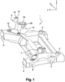
- a cradle 1 preferably made of steel, forming a frame, intended to be disposed at the front of a motor vehicle, between the longitudinal side members of said vehicle, comprises rear fixing means 2, as well as front fixing means . These are in the form of horns 4, allowing an extension along the normalized vertical z axis.
- the side members in their front part, have an elevation for the connection of the powertrain.
- the front part of the cradle comprises substantially vertical surfaces 6 for connecting a shock absorbing element, more commonly known as “crash-box”.
- the cradle structure of the cradle has fixing points 8 for the wheel support arms and suspension elements, not shown.
- the horns 4 connecting the front part of the cradle to the side members, body structure elements are in one-piece form, preferably being from foundry, and advantageously from aluminum foundry, allowing a reduction weight.
- these horns 4 have a flat base 10 in the normalized xy plane, having two holes 12 of vertical axis z for fixing the horns on the upper part of the cradle.
- the horns 4 comprise, in the upper part, a substantially vertical hollow cylinder 14, the opening 15 allowing the connection, by mechanical assembly of screwing type, to the side members, according to the normalized xy plane.
- Other assembly techniques can be envisaged, such as welding, for fixing the horns to the cradle and / or the horns to the side members.
- the horns have a bulged lateral part 16, curved in the shape of a U in an x-z plane, preferably oriented towards the rear of the vehicle when the horn is fixed to the cradle.
- the segments 18a, 18b forming the U have a width l, along the axis y, sufficient for the reception of a bearing 22.
- the segments 18a, 18b have a thickness e, along the axis x, which can be variable depending on the length of the segments, but which is large enough at the free end of the segments so that the flat surfaces 19a, 19b thus produced along an xy plane, allow the fixing of a plate 24, by means of threaded blind holes 20.
- the curved U-shaped shape of the bulged part 16 thus makes it possible to house a bearing 22 preferably made of rubber, for guiding an anti-roll bar 26, partially shown in this figure.
- the plate 24 is a bearing compression plate.
- the embodiment of the curved shape for receiving the bearing has a segment 18b from the massive part of the horn, that is to say located in the general plane yz of the horn, and a segment 18a forming , with the curved part, an extension of the horn longitudinally towards the rear, when the horn is placed on the cradle.
- the segment 18a has a local reduction in thickness in the form of a concavity 28.
- This hollow zone locally makes it possible to weaken the mechanical resistance in order to constitute, in the event of impact, a privileged zone. deformation, or even breakage of the support of the anti-roll bar 26, so that this anti-roll bar and its support can absorb part of the energy in the event of a front impact without generating strong stresses and / or structural modifications horns 4 and side members.
- one-piece horns preferably made of aluminum, comprising a housing for the guide bearing of an anti-roll bar, while having a fusibility zone to allow said bar to “disappear” during an impact. before, considerably reduces the number of parts and fasteners to achieve all of the functions described.
Landscapes
- Engineering & Computer Science (AREA)
- Mechanical Engineering (AREA)
- Chemical & Material Sciences (AREA)
- Combustion & Propulsion (AREA)
- Transportation (AREA)
- Body Structure For Vehicles (AREA)
- Vehicle Body Suspensions (AREA)
- Arrangement Or Mounting Of Propulsion Units For Vehicles (AREA)
Description
- La présente invention se rapporte au domaine technique des berceaux automobile et vise notamment un agencement compact d'une pièce de liaison de tels berceaux à la structure de caisse du véhicule. L'invention est également relative à un véhicule automobile comprenant un tel agencement.
- Il est connu, dans ce domaine technique, des berceaux reliés aux longerons par l'intermédiaire de cornes, tel le document
FR 2 966 418 JP H10 258763 FR 2 960 507 WO 2013/178896 divulgue un ensemble de palier d'articulation d'une barre anti-dévers adapté au logement de palier en forme cintrée en U de réception d'un palier de la présente invention. - La présente invention vise à alléger une telle structure en limitant le nombre de fixations, tout en conservant les propriétés de l'assemblage.
- La présente invention est atteinte à l'aide d'un dispositif de liaison entre un berceau d'un véhicule automobile et un élément de structure de caisse dudit véhicule, ledit dispositif comprenant une corne monobloc présentant une base de raccordement au berceau ainsi qu'une partie supérieure de raccordement à un élément de structure de caisse, la corne présentant, entre la base et la partie supérieur, une partie latérale comportant une forme cintrée en U de réception d'un palier de guidage d'une barre anti-dévers, la partie latérale comportant deux faces planes aux extrémités de la forme en U pour la fixation d'une plaque de compression du palier de guidage,
- l a partie latérale de la corne étant disposée vers l'arrière du véhicule lorsque la corne est fixée sur le berceau, caractérisé en ce que
- l a paroi délimitant la forme cintrée de la partie latérale présente une diminution locale d'épaisseur.
- Selon d'autres caractéristiques complémentaires :
- la corne est en aluminium, issue de moulage, et le berceau est en acier.
- La présente invention vise également un véhicule automobile comportant une caisse supportant un berceau, caractérisé en ce que le berceau est lié à un élément de structure de caisse par un dispositif selon l'une des caractéristiques précédemment mentionnées.
- Avantageusement, le berceau est disposé à l'avant du véhicule.
- La présente invention sera mieux comprise à l'aide de la description qui va suivre, en référence aux figures annexées, parmi lesquelles :
- la
figure 1 est une vue en perspective d'un berceau équipé de la présente invention, - la
figure 2 est une vue en perspective d'une pièce de liaison du berceau à la structure de caisse, - la
figure 3 est une vue analogue à lafigure 2 , où certains éléments complémentaires ont été représentés. - Selon l'invention, en référence à la
figure 1 , un berceau 1, préférentiellement en acier, formant un cadre, prévu pour être disposé à l'avant d'un véhicule automobile, entre les longerons latéraux longitudinaux dudit véhicule, comporte des moyens de fixation arrière 2, ainsi que des moyens de fixation avant. Ces derniers se présentent sous la forme de cornes 4, permettant une extension selon l'axe z vertical normalisé. - En effet, dans la partie avant du véhicule, les longerons, dans leur partie antérieure, présentent une élévation pour la liaison du groupe moto-propulseur.
- La partie avant du berceau comporte des surfaces sensiblement verticales 6 de liaison d'un élément absorbeur de choc, plus communément dénommé « crash-box ». La structure en chape du berceau présente des points de fixation 8 des bras de support de roue et d'éléments de suspension, non représentés.
- Selon l'invention, les cornes 4 de liaison de la partie avant du berceau aux longerons, éléments de structure de caisse, se présentent sous une forme monobloc, en étant préférentiellement issus de fonderie, et avantageusement de fonderie d'aluminium, permettant une réduction de poids.
- En référence également aux
figures 2 et 3 , ces cornes 4 présentent une base plane 10 dans le plan x-y normalisé, possédant deux trous 12 d'axe vertical z pour la fixation des cornes sur la partie supérieure du berceau. - Afin de fixer les cornes aux longerons ou éléments équivalents de structure de caisse, les cornes 4 comportent, en partie supérieure, un cylindre 14 creux sensiblement vertical, l'ouverture 15 permettant la liaison, par assemblage mécanique de type vissage, aux longerons, selon le plan x-y normalisé. D'autres techniques d'assemblage peuvent être envisagées, tel le soudage, pour la fixation des cornes au berceau et/ou des cornes aux longerons.
- Entre la base 10 et le cylindre 14, les cornes présentent une partie latérale renflée 16, cintrée en forme de U dans un plan x-z, préférentiellement orienté vers l'arrière du véhicule lorsque la corne est fixée sur le berceau. Les segments 18a, 18b formant le U présentent une largeur ℓ, selon l'axe y, suffisante pour la réception d'un palier 22.
- Par ailleurs, les segments 18a, 18b présentent une épaisseur e, selon l'axe x, qui peut être variable selon la longueur des segments, mais qui est suffisamment importante à l'extrémité libre des segments pour que les surfaces planes 19a, 19b ainsi réalisées selon un plan x-y, permettent la fixation d'une plaque 24, par l'intermédiaire de trous borgnes filetés 20.
- Tel que le montre la
figure 3 , la forme cintrée en U de la partie renflée 16 permet ainsi de loger un palier 22 préférentiellement en caoutchouc, de guidage d'une barre anti-dévers 26, représentée partiellement sur cette figure. La plaque 24 est une plaque de compression du palier. - Selon l'invention, la réalisation de la forme cintrée de réception du palier présente un segment 18b issu de la partie massive de la corne, c'est-à-dire situé dans le plan général y-z de la corne, et un segment 18a formant, avec la partie cintrée, une extension de la corne longitudinalement vers l'arrière, lorsque la corne est mise en place sur le berceau.
- Selon l'invention, le segment 18a présente une réduction locale d'épaisseur sous la forme d'une concavité 28. Cette zone en creux permet, localement, d'affaiblir la résistance mécanique afin de constituer, en cas de choc, une zone privilégiée de déformation, voire de rupture du support de la barre anti-dévers 26, afin que cette barre anti-dévers et son support puissent absorber une partie de l'énergie en cas de choc avant sans générer de contraintes fortes et/ou de modifications structurelles des cornes 4 et des longerons.
- Ainsi, la réalisation de cornes monobloc, préférentiellement en aluminium, comportant un logement de palier de guidage d'une barre anti-dévers, tout en présentant une zone de fusibilité pour permettre à ladite barre de « s'effacer » lors d'un choc avant, réduit considérablement le nombre de pièces et de fixations pour réaliser l'ensemble des fonctions décrites.
Claims (4)
- Dispositif de liaison entre un berceau (1) d'un véhicule automobile et un élément de structure de caisse dudit véhicule, ledit dispositif comprenant une corne (4) monobloc présentant une base (10) de raccordement au berceau (1) ainsi qu'une partie supérieure de raccordement à un élément de structure de caisse, corne (4) présentant entre la base (10) et la partie supérieure, une partie latérale (16) comportant une forme cintrée en U de réception d'un palier (22) de guidage d'une barre anti-dévers (26), la partie latérale (16) comportant deux faces planes (19a, 19b) aux extrémités de la forme en U pour la fixation d'une plaque de compression (24) du palier de guidage (22), la partie latérale (16) étant disposée vers l'arrière du véhicule lorsque la corne (4) est fixée sur le berceau, caractérisé en ce que la paroi délimitant la forme cintrée de la partie latérale (16) présente une diminution locale d'épaisseur (28).
- Dispositif selon la revendication 1, caractérisé en ce que la corne (4) est en aluminium, issue de moulage, et le berceau est en acier.
- Véhicule automobile comportant une caisse supportant un berceau, caractérisé en ce que le berceau est lié à un élément de structure de caisse par un dispositif conforme à l'une des revendications 1 à 2.
- Véhicule selon la revendication précédente, caractérisé en ce que le berceau est disposé à l'avant du véhicule.
Applications Claiming Priority (2)
| Application Number | Priority Date | Filing Date | Title |
|---|---|---|---|
| FR1262392A FR3000009B1 (fr) | 2012-12-20 | 2012-12-20 | Dispositif de liaison d'un berceau automobile |
| PCT/EP2013/071982 WO2014095124A1 (fr) | 2012-12-20 | 2013-10-21 | Dispositif de liaison d'un berceau automobile |
Publications (2)
| Publication Number | Publication Date |
|---|---|
| EP2934988A1 EP2934988A1 (fr) | 2015-10-28 |
| EP2934988B1 true EP2934988B1 (fr) | 2020-03-04 |
Family
ID=48521048
Family Applications (1)
| Application Number | Title | Priority Date | Filing Date |
|---|---|---|---|
| EP13779833.6A Active EP2934988B1 (fr) | 2012-12-20 | 2013-10-21 | Dispositif de liaison d'un berceau automobile |
Country Status (8)
| Country | Link |
|---|---|
| US (1) | US9616737B2 (fr) |
| EP (1) | EP2934988B1 (fr) |
| JP (1) | JP6293783B2 (fr) |
| KR (1) | KR101968678B1 (fr) |
| CN (1) | CN104822582B (fr) |
| FR (1) | FR3000009B1 (fr) |
| RU (1) | RU2633420C2 (fr) |
| WO (1) | WO2014095124A1 (fr) |
Families Citing this family (11)
| Publication number | Priority date | Publication date | Assignee | Title |
|---|---|---|---|---|
| JP6369427B2 (ja) * | 2015-09-04 | 2018-08-08 | トヨタ自動車株式会社 | 車両下部構造 |
| DE102015013780A1 (de) * | 2015-10-24 | 2017-04-27 | Audi Ag | Befestigungsanordnung zur Befestigung eines Aggregat- und Stabilisatorlagers |
| US20160332511A1 (en) * | 2016-07-25 | 2016-11-17 | Caterpillar Inc. | Mounting assembly |
| FR3059630B1 (fr) * | 2016-12-06 | 2020-02-14 | Renault S.A.S | Assemblage d'un berceau de vehicule sur caisse comportant une piece de fonderie |
| FR3080079B1 (fr) * | 2018-04-16 | 2020-03-27 | Psa Automobiles Sa | Corne pour berceau d’un vehicule automobile |
| USD968467S1 (en) | 2019-09-30 | 2022-11-01 | Cnh Industrial America Llc | Engine mount for a work vehicle |
| US11345403B2 (en) | 2019-09-30 | 2022-05-31 | Cnh Industrial America Llc | Engine mounting system for a work vehicle |
| US11453440B2 (en) * | 2020-03-18 | 2022-09-27 | Volvo Car Corporation | Subframe assembly for a vehicle |
| CN113442997B (zh) * | 2021-06-28 | 2024-08-30 | 重庆新盛智博科技有限公司 | 一种自动驾驶转向器总成 |
| FR3164151A1 (fr) * | 2024-07-05 | 2026-01-09 | Stellantis Auto Sas | Corne de berceau intégrant une cale de suspension pour groupe électromoteur de véhicule automobile |
| DE102024134261A1 (de) * | 2024-11-21 | 2025-10-02 | Mercedes-Benz Group AG | Integralträger für einen Kraftwagen sowie Anordnung |
Family Cites Families (20)
| Publication number | Priority date | Publication date | Assignee | Title |
|---|---|---|---|---|
| JPS62289415A (ja) * | 1986-06-06 | 1987-12-16 | Toyota Motor Corp | 車体懸架装置のロアア−ム支持構造 |
| JP2963749B2 (ja) * | 1990-09-26 | 1999-10-18 | マツダ株式会社 | 自動車の前部車体構造 |
| US5718407A (en) * | 1995-09-14 | 1998-02-17 | Hyundai Motor Company | Power unit mounting system |
| GB9521852D0 (en) * | 1995-10-25 | 1996-01-03 | Jaguar Cars | Improvements in and relating to anti-roll bar assemblies for road vehicles |
| JPH10258763A (ja) * | 1997-03-18 | 1998-09-29 | Nissan Motor Co Ltd | サスペンションサブフレーム構造 |
| US6435297B1 (en) * | 1999-11-29 | 2002-08-20 | Cosma International Inc. | Vehicle component mounting assembly |
| RU2176606C2 (ru) * | 2000-02-07 | 2001-12-10 | Открытое акционерное общество "КАМАЗ" | Рама транспортного средства |
| DE10221299C1 (de) * | 2002-05-14 | 2003-10-30 | Porsche Ag | Fahrschemel für eine Vorderachse eines Kraftfahrzeugs |
| JP4044803B2 (ja) * | 2002-07-22 | 2008-02-06 | マツダ株式会社 | 車両のスタビライザ取付構造 |
| US7320480B2 (en) * | 2003-03-27 | 2008-01-22 | Unisia Jkc Steering Systems, Co., Ltd. | Structure for fixing steering-gear housing |
| JP4231473B2 (ja) * | 2004-10-19 | 2009-02-25 | 本田技研工業株式会社 | ステアリングギヤボックス取付構造 |
| JP4804942B2 (ja) * | 2005-10-13 | 2011-11-02 | ダイハツ工業株式会社 | 自動車の前部車体構造 |
| FR2922160A1 (fr) * | 2007-10-15 | 2009-04-17 | Peugeot Citroen Automobiles Sa | Fixation de barre anti-devers sur un train avant de vehicule automobile |
| DE102009042060A1 (de) * | 2009-09-17 | 2011-03-24 | GM Global Technology Operations, Inc., Detroit | Strukturbauteil für Hinterrahmenstruktur eines Kraftfahrzeugs |
| FR2960507A1 (fr) * | 2010-05-31 | 2011-12-02 | Peugeot Citroen Automobiles Sa | Berceau a cornes pour train avant a barre anti-devers de vehicule |
| JP5581911B2 (ja) * | 2010-09-02 | 2014-09-03 | スズキ株式会社 | トレーリングアームの取付構造 |
| JP5299470B2 (ja) * | 2011-05-16 | 2013-09-25 | 日産自動車株式会社 | サスペンション構造、サスペンションリンク形成方法 |
| KR101542956B1 (ko) * | 2011-07-29 | 2015-08-07 | 현대자동차 주식회사 | 자동차용 스태빌라이저 바의 마운트 부시 |
| US8646792B2 (en) * | 2012-04-12 | 2014-02-11 | Toyota Motor Engineering & Manufacturing North America, Inc. | Subframe intrusion control by steering gear catcher |
| FR2991236B1 (fr) * | 2012-05-29 | 2014-06-13 | Renault Sa | "ensemble de palier d'articulation pour une barre anti-devers" |
-
2012
- 2012-12-20 FR FR1262392A patent/FR3000009B1/fr not_active Expired - Fee Related
-
2013
- 2013-10-21 RU RU2015129579A patent/RU2633420C2/ru active
- 2013-10-21 CN CN201380062735.0A patent/CN104822582B/zh not_active Expired - Fee Related
- 2013-10-21 EP EP13779833.6A patent/EP2934988B1/fr active Active
- 2013-10-21 US US14/652,567 patent/US9616737B2/en not_active Expired - Fee Related
- 2013-10-21 WO PCT/EP2013/071982 patent/WO2014095124A1/fr not_active Ceased
- 2013-10-21 KR KR1020157018855A patent/KR101968678B1/ko active Active
- 2013-10-21 JP JP2015548300A patent/JP6293783B2/ja not_active Expired - Fee Related
Non-Patent Citations (1)
| Title |
|---|
| None * |
Also Published As
| Publication number | Publication date |
|---|---|
| RU2015129579A (ru) | 2017-01-26 |
| FR3000009A1 (fr) | 2014-06-27 |
| EP2934988A1 (fr) | 2015-10-28 |
| WO2014095124A1 (fr) | 2014-06-26 |
| KR20150096715A (ko) | 2015-08-25 |
| CN104822582A (zh) | 2015-08-05 |
| JP6293783B2 (ja) | 2018-03-14 |
| RU2633420C2 (ru) | 2017-10-12 |
| US20150328970A1 (en) | 2015-11-19 |
| JP2016504234A (ja) | 2016-02-12 |
| CN104822582B (zh) | 2018-03-16 |
| FR3000009B1 (fr) | 2018-08-03 |
| US9616737B2 (en) | 2017-04-11 |
| KR101968678B1 (ko) | 2019-04-12 |
Similar Documents
| Publication | Publication Date | Title |
|---|---|---|
| EP2934988B1 (fr) | Dispositif de liaison d'un berceau automobile | |
| EP2930067B1 (fr) | Poutre de pare-chocs de véhicule, ensemble pare-chocs et véhicule associés | |
| FR2925009A1 (fr) | Poutre pour tableau de bord de vehicule automobile | |
| EP3003826B1 (fr) | Berceau pour train roulant de véhicule automobile | |
| EP4511277B1 (fr) | Véhicule automobile comprenant un longeron avec une pièce de renfort | |
| EP2436579A2 (fr) | Ensemble de traverse de planche de bord pour véhicule automobile. | |
| FR3006979A1 (fr) | Agencement de carrosserie dote d'un agencement de protection pour pieces jouant un role au niveau de la securite dans le domaine des vehicules automobiles | |
| WO2011023871A1 (fr) | Vehicule comportant un ensemble ressort amortisseur | |
| EP3810492B1 (fr) | Caisse de vehicule automobile, comprenant un element deformable de fixation d'un support de reception d'un enrouleur d'une ceinture de securite | |
| EP4540124A1 (fr) | Structure de partie arrière de caisse de véhicule automobile et véhicule comprenant une telle structure | |
| EP3077226B1 (fr) | Bras de suspension d'un vehicule automobile destine a absorber un choc lateral | |
| EP2632788B1 (fr) | Agencement pour la liaison entre un berceau et les longerons | |
| FR3136738A1 (fr) | Structure de partie arrière de caisse de véhicule automobile et véhicule comprenant une telle structure | |
| EP3752722B1 (fr) | Véhicule automobile á crochet d'échappement relié au silencieux par des moyens de rupture prédéterminée | |
| FR2926280A1 (fr) | Element de renfort lateral pour bloc avant de vehicule automobile et vehicule automobile equipe d'un tel element | |
| EP3686093B1 (fr) | Structure arriere de vehicule automobile equipee d'une structure de support d'un dispositif de retenue de roue de secours sous plancher | |
| EP4072927B1 (fr) | Dispositif de renfort d'une traverse de poste de conduite d'un véhicule automobile | |
| EP2132062B1 (fr) | Assemblage de fixation d'un module de coussin de securite sur une structure mecaniquement resistante de la planche de bord | |
| FR3148978A1 (fr) | Longeron pour structure de véhicule automobile | |
| FR3133039A1 (fr) | Dispositif pour l’arrimage des moyens de remorquage des véhicules automobiles | |
| FR3158695A1 (fr) | Structure de caisse de véhicule automobile et véhicule comprenant une telle structure | |
| FR3012372A1 (fr) | Train arriere a traverse deformable comportant des combines tournes vers l'avant, fixes au bras de suspension sous l'articulation | |
| FR2982814A1 (fr) | Systeme de resistance aux chocs comprenant une piece de renfort. | |
| FR3081417A1 (fr) | Dispositif de protection d’une batterie de vehicule installee entre des coupelles d’appui de ressort d’une traverse arriere deformable | |
| EP2366574A1 (fr) | Agencement d'un filet anti remous a l'interieur d'un vehicule automobile du type cabriolet |
Legal Events
| Date | Code | Title | Description |
|---|---|---|---|
| PUAI | Public reference made under article 153(3) epc to a published international application that has entered the european phase |
Free format text: ORIGINAL CODE: 0009012 |
|
| 17P | Request for examination filed |
Effective date: 20150409 |
|
| AK | Designated contracting states |
Kind code of ref document: A1 Designated state(s): AL AT BE BG CH CY CZ DE DK EE ES FI FR GB GR HR HU IE IS IT LI LT LU LV MC MK MT NL NO PL PT RO RS SE SI SK SM TR |
|
| AX | Request for extension of the european patent |
Extension state: BA ME |
|
| DAX | Request for extension of the european patent (deleted) | ||
| STAA | Information on the status of an ep patent application or granted ep patent |
Free format text: STATUS: EXAMINATION IS IN PROGRESS |
|
| 17Q | First examination report despatched |
Effective date: 20180709 |
|
| GRAP | Despatch of communication of intention to grant a patent |
Free format text: ORIGINAL CODE: EPIDOSNIGR1 |
|
| STAA | Information on the status of an ep patent application or granted ep patent |
Free format text: STATUS: GRANT OF PATENT IS INTENDED |
|
| INTG | Intention to grant announced |
Effective date: 20190926 |
|
| RIN1 | Information on inventor provided before grant (corrected) |
Inventor name: BOURLON, FRANCK Inventor name: DUBREUIL, BERTRAND |
|
| GRAS | Grant fee paid |
Free format text: ORIGINAL CODE: EPIDOSNIGR3 |
|
| GRAA | (expected) grant |
Free format text: ORIGINAL CODE: 0009210 |
|
| STAA | Information on the status of an ep patent application or granted ep patent |
Free format text: STATUS: THE PATENT HAS BEEN GRANTED |
|
| AK | Designated contracting states |
Kind code of ref document: B1 Designated state(s): AL AT BE BG CH CY CZ DE DK EE ES FI FR GB GR HR HU IE IS IT LI LT LU LV MC MK MT NL NO PL PT RO RS SE SI SK SM TR |
|
| REG | Reference to a national code |
Ref country code: GB Ref legal event code: FG4D Free format text: NOT ENGLISH |
|
| REG | Reference to a national code |
Ref country code: CH Ref legal event code: EP |
|
| REG | Reference to a national code |
Ref country code: AT Ref legal event code: REF Ref document number: 1240058 Country of ref document: AT Kind code of ref document: T Effective date: 20200315 |
|
| REG | Reference to a national code |
Ref country code: DE Ref legal event code: R096 Ref document number: 602013066485 Country of ref document: DE |
|
| REG | Reference to a national code |
Ref country code: IE Ref legal event code: FG4D Free format text: LANGUAGE OF EP DOCUMENT: FRENCH |
|
| PG25 | Lapsed in a contracting state [announced via postgrant information from national office to epo] |
Ref country code: FI Free format text: LAPSE BECAUSE OF FAILURE TO SUBMIT A TRANSLATION OF THE DESCRIPTION OR TO PAY THE FEE WITHIN THE PRESCRIBED TIME-LIMIT Effective date: 20200304 Ref country code: RS Free format text: LAPSE BECAUSE OF FAILURE TO SUBMIT A TRANSLATION OF THE DESCRIPTION OR TO PAY THE FEE WITHIN THE PRESCRIBED TIME-LIMIT Effective date: 20200304 Ref country code: NO Free format text: LAPSE BECAUSE OF FAILURE TO SUBMIT A TRANSLATION OF THE DESCRIPTION OR TO PAY THE FEE WITHIN THE PRESCRIBED TIME-LIMIT Effective date: 20200604 |
|
| REG | Reference to a national code |
Ref country code: NL Ref legal event code: MP Effective date: 20200304 |
|
| PG25 | Lapsed in a contracting state [announced via postgrant information from national office to epo] |
Ref country code: BG Free format text: LAPSE BECAUSE OF FAILURE TO SUBMIT A TRANSLATION OF THE DESCRIPTION OR TO PAY THE FEE WITHIN THE PRESCRIBED TIME-LIMIT Effective date: 20200604 Ref country code: HR Free format text: LAPSE BECAUSE OF FAILURE TO SUBMIT A TRANSLATION OF THE DESCRIPTION OR TO PAY THE FEE WITHIN THE PRESCRIBED TIME-LIMIT Effective date: 20200304 Ref country code: LV Free format text: LAPSE BECAUSE OF FAILURE TO SUBMIT A TRANSLATION OF THE DESCRIPTION OR TO PAY THE FEE WITHIN THE PRESCRIBED TIME-LIMIT Effective date: 20200304 Ref country code: SE Free format text: LAPSE BECAUSE OF FAILURE TO SUBMIT A TRANSLATION OF THE DESCRIPTION OR TO PAY THE FEE WITHIN THE PRESCRIBED TIME-LIMIT Effective date: 20200304 Ref country code: GR Free format text: LAPSE BECAUSE OF FAILURE TO SUBMIT A TRANSLATION OF THE DESCRIPTION OR TO PAY THE FEE WITHIN THE PRESCRIBED TIME-LIMIT Effective date: 20200605 |
|
| REG | Reference to a national code |
Ref country code: LT Ref legal event code: MG4D |
|
| PG25 | Lapsed in a contracting state [announced via postgrant information from national office to epo] |
Ref country code: NL Free format text: LAPSE BECAUSE OF FAILURE TO SUBMIT A TRANSLATION OF THE DESCRIPTION OR TO PAY THE FEE WITHIN THE PRESCRIBED TIME-LIMIT Effective date: 20200304 |
|
| PG25 | Lapsed in a contracting state [announced via postgrant information from national office to epo] |
Ref country code: LT Free format text: LAPSE BECAUSE OF FAILURE TO SUBMIT A TRANSLATION OF THE DESCRIPTION OR TO PAY THE FEE WITHIN THE PRESCRIBED TIME-LIMIT Effective date: 20200304 Ref country code: EE Free format text: LAPSE BECAUSE OF FAILURE TO SUBMIT A TRANSLATION OF THE DESCRIPTION OR TO PAY THE FEE WITHIN THE PRESCRIBED TIME-LIMIT Effective date: 20200304 Ref country code: SM Free format text: LAPSE BECAUSE OF FAILURE TO SUBMIT A TRANSLATION OF THE DESCRIPTION OR TO PAY THE FEE WITHIN THE PRESCRIBED TIME-LIMIT Effective date: 20200304 Ref country code: SK Free format text: LAPSE BECAUSE OF FAILURE TO SUBMIT A TRANSLATION OF THE DESCRIPTION OR TO PAY THE FEE WITHIN THE PRESCRIBED TIME-LIMIT Effective date: 20200304 Ref country code: IS Free format text: LAPSE BECAUSE OF FAILURE TO SUBMIT A TRANSLATION OF THE DESCRIPTION OR TO PAY THE FEE WITHIN THE PRESCRIBED TIME-LIMIT Effective date: 20200704 Ref country code: CZ Free format text: LAPSE BECAUSE OF FAILURE TO SUBMIT A TRANSLATION OF THE DESCRIPTION OR TO PAY THE FEE WITHIN THE PRESCRIBED TIME-LIMIT Effective date: 20200304 Ref country code: PT Free format text: LAPSE BECAUSE OF FAILURE TO SUBMIT A TRANSLATION OF THE DESCRIPTION OR TO PAY THE FEE WITHIN THE PRESCRIBED TIME-LIMIT Effective date: 20200729 Ref country code: ES Free format text: LAPSE BECAUSE OF FAILURE TO SUBMIT A TRANSLATION OF THE DESCRIPTION OR TO PAY THE FEE WITHIN THE PRESCRIBED TIME-LIMIT Effective date: 20200304 Ref country code: RO Free format text: LAPSE BECAUSE OF FAILURE TO SUBMIT A TRANSLATION OF THE DESCRIPTION OR TO PAY THE FEE WITHIN THE PRESCRIBED TIME-LIMIT Effective date: 20200304 |
|
| REG | Reference to a national code |
Ref country code: AT Ref legal event code: MK05 Ref document number: 1240058 Country of ref document: AT Kind code of ref document: T Effective date: 20200304 |
|
| REG | Reference to a national code |
Ref country code: DE Ref legal event code: R097 Ref document number: 602013066485 Country of ref document: DE |
|
| PLBE | No opposition filed within time limit |
Free format text: ORIGINAL CODE: 0009261 |
|
| STAA | Information on the status of an ep patent application or granted ep patent |
Free format text: STATUS: NO OPPOSITION FILED WITHIN TIME LIMIT |
|
| PG25 | Lapsed in a contracting state [announced via postgrant information from national office to epo] |
Ref country code: IT Free format text: LAPSE BECAUSE OF FAILURE TO SUBMIT A TRANSLATION OF THE DESCRIPTION OR TO PAY THE FEE WITHIN THE PRESCRIBED TIME-LIMIT Effective date: 20200304 Ref country code: DK Free format text: LAPSE BECAUSE OF FAILURE TO SUBMIT A TRANSLATION OF THE DESCRIPTION OR TO PAY THE FEE WITHIN THE PRESCRIBED TIME-LIMIT Effective date: 20200304 Ref country code: AT Free format text: LAPSE BECAUSE OF FAILURE TO SUBMIT A TRANSLATION OF THE DESCRIPTION OR TO PAY THE FEE WITHIN THE PRESCRIBED TIME-LIMIT Effective date: 20200304 |
|
| 26N | No opposition filed |
Effective date: 20201207 |
|
| PG25 | Lapsed in a contracting state [announced via postgrant information from national office to epo] |
Ref country code: PL Free format text: LAPSE BECAUSE OF FAILURE TO SUBMIT A TRANSLATION OF THE DESCRIPTION OR TO PAY THE FEE WITHIN THE PRESCRIBED TIME-LIMIT Effective date: 20200304 Ref country code: SI Free format text: LAPSE BECAUSE OF FAILURE TO SUBMIT A TRANSLATION OF THE DESCRIPTION OR TO PAY THE FEE WITHIN THE PRESCRIBED TIME-LIMIT Effective date: 20200304 |
|
| REG | Reference to a national code |
Ref country code: CH Ref legal event code: PL |
|
| PG25 | Lapsed in a contracting state [announced via postgrant information from national office to epo] |
Ref country code: LU Free format text: LAPSE BECAUSE OF NON-PAYMENT OF DUE FEES Effective date: 20201021 Ref country code: MC Free format text: LAPSE BECAUSE OF FAILURE TO SUBMIT A TRANSLATION OF THE DESCRIPTION OR TO PAY THE FEE WITHIN THE PRESCRIBED TIME-LIMIT Effective date: 20200304 |
|
| REG | Reference to a national code |
Ref country code: BE Ref legal event code: MM Effective date: 20201031 |
|
| PG25 | Lapsed in a contracting state [announced via postgrant information from national office to epo] |
Ref country code: LI Free format text: LAPSE BECAUSE OF NON-PAYMENT OF DUE FEES Effective date: 20201031 Ref country code: CH Free format text: LAPSE BECAUSE OF NON-PAYMENT OF DUE FEES Effective date: 20201031 Ref country code: BE Free format text: LAPSE BECAUSE OF NON-PAYMENT OF DUE FEES Effective date: 20201031 |
|
| PG25 | Lapsed in a contracting state [announced via postgrant information from national office to epo] |
Ref country code: IE Free format text: LAPSE BECAUSE OF NON-PAYMENT OF DUE FEES Effective date: 20201021 |
|
| PG25 | Lapsed in a contracting state [announced via postgrant information from national office to epo] |
Ref country code: TR Free format text: LAPSE BECAUSE OF FAILURE TO SUBMIT A TRANSLATION OF THE DESCRIPTION OR TO PAY THE FEE WITHIN THE PRESCRIBED TIME-LIMIT Effective date: 20200304 Ref country code: MT Free format text: LAPSE BECAUSE OF FAILURE TO SUBMIT A TRANSLATION OF THE DESCRIPTION OR TO PAY THE FEE WITHIN THE PRESCRIBED TIME-LIMIT Effective date: 20200304 Ref country code: CY Free format text: LAPSE BECAUSE OF FAILURE TO SUBMIT A TRANSLATION OF THE DESCRIPTION OR TO PAY THE FEE WITHIN THE PRESCRIBED TIME-LIMIT Effective date: 20200304 |
|
| PG25 | Lapsed in a contracting state [announced via postgrant information from national office to epo] |
Ref country code: MK Free format text: LAPSE BECAUSE OF FAILURE TO SUBMIT A TRANSLATION OF THE DESCRIPTION OR TO PAY THE FEE WITHIN THE PRESCRIBED TIME-LIMIT Effective date: 20200304 Ref country code: AL Free format text: LAPSE BECAUSE OF FAILURE TO SUBMIT A TRANSLATION OF THE DESCRIPTION OR TO PAY THE FEE WITHIN THE PRESCRIBED TIME-LIMIT Effective date: 20200304 |
|
| P01 | Opt-out of the competence of the unified patent court (upc) registered |
Effective date: 20230608 |
|
| PGFP | Annual fee paid to national office [announced via postgrant information from national office to epo] |
Ref country code: GB Payment date: 20231020 Year of fee payment: 11 |
|
| GBPC | Gb: european patent ceased through non-payment of renewal fee |
Effective date: 20241021 |
|
| PG25 | Lapsed in a contracting state [announced via postgrant information from national office to epo] |
Ref country code: GB Free format text: LAPSE BECAUSE OF NON-PAYMENT OF DUE FEES Effective date: 20241021 |
|
| PGFP | Annual fee paid to national office [announced via postgrant information from national office to epo] |
Ref country code: DE Payment date: 20251021 Year of fee payment: 13 |
|
| PGFP | Annual fee paid to national office [announced via postgrant information from national office to epo] |
Ref country code: FR Payment date: 20251030 Year of fee payment: 13 |