EP2935807B1 - Konzentrierendes thermodynamisches solar- oder konventionelles wärmekraftwerk - Google Patents
Konzentrierendes thermodynamisches solar- oder konventionelles wärmekraftwerk Download PDFInfo
- Publication number
- EP2935807B1 EP2935807B1 EP13826989.9A EP13826989A EP2935807B1 EP 2935807 B1 EP2935807 B1 EP 2935807B1 EP 13826989 A EP13826989 A EP 13826989A EP 2935807 B1 EP2935807 B1 EP 2935807B1
- Authority
- EP
- European Patent Office
- Prior art keywords
- tank
- liquid
- steam
- power plant
- tanks
- Prior art date
- Legal status (The legal status is an assumption and is not a legal conclusion. Google has not performed a legal analysis and makes no representation as to the accuracy of the status listed.)
- Active
Links
Images



Classifications
-
- F—MECHANICAL ENGINEERING; LIGHTING; HEATING; WEAPONS; BLASTING
- F01—MACHINES OR ENGINES IN GENERAL; ENGINE PLANTS IN GENERAL; STEAM ENGINES
- F01K—STEAM ENGINE PLANTS; STEAM ACCUMULATORS; ENGINE PLANTS NOT OTHERWISE PROVIDED FOR; ENGINES USING SPECIAL WORKING FLUIDS OR CYCLES
- F01K3/00—Plants characterised by the use of steam or heat accumulators, or intermediate steam heaters, therein
- F01K3/004—Accumulation in the liquid branch of the circuit
-
- F—MECHANICAL ENGINEERING; LIGHTING; HEATING; WEAPONS; BLASTING
- F01—MACHINES OR ENGINES IN GENERAL; ENGINE PLANTS IN GENERAL; STEAM ENGINES
- F01D—NON-POSITIVE DISPLACEMENT MACHINES OR ENGINES, e.g. STEAM TURBINES
- F01D15/00—Adaptations of machines or engines for special use; Combinations of engines with devices driven thereby
- F01D15/10—Adaptations for driving, or combinations with, electric generators
-
- F—MECHANICAL ENGINEERING; LIGHTING; HEATING; WEAPONS; BLASTING
- F01—MACHINES OR ENGINES IN GENERAL; ENGINE PLANTS IN GENERAL; STEAM ENGINES
- F01K—STEAM ENGINE PLANTS; STEAM ACCUMULATORS; ENGINE PLANTS NOT OTHERWISE PROVIDED FOR; ENGINES USING SPECIAL WORKING FLUIDS OR CYCLES
- F01K1/00—Steam accumulators
- F01K1/12—Multiple accumulators; Charging, discharging or control specially adapted therefor
-
- F—MECHANICAL ENGINEERING; LIGHTING; HEATING; WEAPONS; BLASTING
- F01—MACHINES OR ENGINES IN GENERAL; ENGINE PLANTS IN GENERAL; STEAM ENGINES
- F01K—STEAM ENGINE PLANTS; STEAM ACCUMULATORS; ENGINE PLANTS NOT OTHERWISE PROVIDED FOR; ENGINES USING SPECIAL WORKING FLUIDS OR CYCLES
- F01K27/00—Plants for converting heat or fluid energy into mechanical energy, not otherwise provided for
- F01K27/005—Plants for converting heat or fluid energy into mechanical energy, not otherwise provided for by means of hydraulic motors
-
- F—MECHANICAL ENGINEERING; LIGHTING; HEATING; WEAPONS; BLASTING
- F02—COMBUSTION ENGINES; HOT-GAS OR COMBUSTION-PRODUCT ENGINE PLANTS
- F02G—HOT GAS OR COMBUSTION-PRODUCT POSITIVE-DISPLACEMENT ENGINE PLANTS; USE OF WASTE HEAT OF COMBUSTION ENGINES; NOT OTHERWISE PROVIDED FOR
- F02G5/00—Profiting from waste heat of combustion engines, not otherwise provided for
- F02G5/02—Profiting from waste heat of exhaust gases
-
- F—MECHANICAL ENGINEERING; LIGHTING; HEATING; WEAPONS; BLASTING
- F03—MACHINES OR ENGINES FOR LIQUIDS; WIND, SPRING, OR WEIGHT MOTORS; PRODUCING MECHANICAL POWER OR A REACTIVE PROPULSIVE THRUST, NOT OTHERWISE PROVIDED FOR
- F03G—SPRING, WEIGHT, INERTIA OR LIKE MOTORS; MECHANICAL-POWER PRODUCING DEVICES OR MECHANISMS, NOT OTHERWISE PROVIDED FOR OR USING ENERGY SOURCES NOT OTHERWISE PROVIDED FOR
- F03G6/00—Devices for producing mechanical power from solar energy
- F03G6/06—Devices for producing mechanical power from solar energy with solar energy concentrating means
- F03G6/065—Devices for producing mechanical power from solar energy with solar energy concentrating means having a Rankine cycle
-
- Y—GENERAL TAGGING OF NEW TECHNOLOGICAL DEVELOPMENTS; GENERAL TAGGING OF CROSS-SECTIONAL TECHNOLOGIES SPANNING OVER SEVERAL SECTIONS OF THE IPC; TECHNICAL SUBJECTS COVERED BY FORMER USPC CROSS-REFERENCE ART COLLECTIONS [XRACs] AND DIGESTS
- Y02—TECHNOLOGIES OR APPLICATIONS FOR MITIGATION OR ADAPTATION AGAINST CLIMATE CHANGE
- Y02E—REDUCTION OF GREENHOUSE GAS [GHG] EMISSIONS, RELATED TO ENERGY GENERATION, TRANSMISSION OR DISTRIBUTION
- Y02E10/00—Energy generation through renewable energy sources
- Y02E10/40—Solar thermal energy, e.g. solar towers
- Y02E10/46—Conversion of thermal power into mechanical power, e.g. Rankine, Stirling or solar thermal engines
-
- Y—GENERAL TAGGING OF NEW TECHNOLOGICAL DEVELOPMENTS; GENERAL TAGGING OF CROSS-SECTIONAL TECHNOLOGIES SPANNING OVER SEVERAL SECTIONS OF THE IPC; TECHNICAL SUBJECTS COVERED BY FORMER USPC CROSS-REFERENCE ART COLLECTIONS [XRACs] AND DIGESTS
- Y02—TECHNOLOGIES OR APPLICATIONS FOR MITIGATION OR ADAPTATION AGAINST CLIMATE CHANGE
- Y02E—REDUCTION OF GREENHOUSE GAS [GHG] EMISSIONS, RELATED TO ENERGY GENERATION, TRANSMISSION OR DISTRIBUTION
- Y02E20/00—Combustion technologies with mitigation potential
- Y02E20/14—Combined heat and power generation [CHP]
Definitions
- concentrating solar power plants using a series of parabolic, cylindroparabolic or Fresnel mirrors are known for concentrating solar energy on a heating body to produce superheated steam.
- the known solar power plants are based on the Rankine cycle, in which the superheated steam (for example at 550 ° C., for a pressure of 140 10 5 Pa) is expanded in steam turbines.
- the overall efficiency of such plants is limited to less than 18%, that is to say that for a ground power of the sun of 1000W / m 2 , one is able to recover maximum 180W / m 2 .
- Wind turbines are also known to produce electricity.
- the blades of the wind turbine are mounted on a shaft which is adapted to rotate the shaft of an alternator.
- the machine according to AT 506796 works at low temperatures (below 100 ° C). If a heating temperature of the water to be pressurized with isobutane 70 ° C and a temperature of 40 ° C at the condenser, the theoretical yield of the machine would be less than 9%, which will say to those skilled in the art that the effective efficiency of this process will be zero, or even negative, taking into consideration the various heat losses, friction, etc.). Finally, given the operating temperatures of the process according to AT 506796 , the maximum pressure of operation will be 7bars.
- a boiler for a fluid having a high degree of expansion.
- This boiler comprises a part in contact with combustion fumes and a part for heating a secondary fluid.
- the primary fluid must remain liquid. If the fluid is water, the volume variation of the liquid water will be only about 2% for a temperature variation of about 50 ° C. This expansion of the liquid water will then generate an overpressure in the upper bell comprising the wheel. The water level at the wheel will be lowered. Such a device will not produce energy, but will be a brake to the flow of hot water to the secondary heat exchanger.
- the invention relates to a device allowing significant real yields, for example 35% and more and maximum yields determined by the Carnot cycle important, for example more than 50 or 60%.
- the insulating element (K) covers more than 90%, advantageously more than 99% of the surface of the liquid in the tank (R1, R2).
- the insulating element preferably covers substantially the entire free surface of the liquid in the tank, thereby acting as a kind of insulating piston.
- the insulating element is for example made of a rigid foam of low density and closed cells.
- the insulating element may also comprise a series of distinct insulating elements able to float on the surface of the liquid. This series of floating elements can then form either an insulating bed or an insulating joint around a central insulating element.
- the reservoir or reservoirs have an elongated shape and are associated with an elongate float floatable on the surface of the liquid present in the reservoir, said float being adapted to define in a reservoir considered an upper portion adapted to receive substantially only superheated steam, and possibly condensing liquid from the superheated steam, and a lower part adapted to receive substantially liquid from the Pelton turbine, the upper part being provided with at least one insulation.
- the present invention also advantageously utilizes a Rankine cycle to achieve superheated steam under pressure.
- Said steam is placed in communication with a cylinder filled with water.
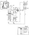
- the water contained in the cylinder R1, pressurized by said steam, is then used to feed the nozzle of the Pelton P ( Fig. 4 ).
- the amount of steam admitted into the cylinder R1 will be regulated by the valve or valve V2 ( Fig. 4 ).
- the superheated steam at the pressure Pa is then released from the pressure Pa to the pressure Pb ( Fig. 2 ).
- the cylinder R1 will be thermally insulated so that the trigger AB is the most isentropic possible.
- the superheated steam pressure goes from 50 10 5 Pa to 30 10 5 Pa
- the Pelton turbine is advantageously dimensioned at a pressure of 40 10 5 Pa for its nominal point. Under these conditions, the yield of the Pelton passes successively from 90% to 91.7% then to 90%. Over this range of 50 10 5 Pa to 30 10 5 Pa, the average efficiency of the Pelton turbine is 90.85%. If the heat losses of the cylinder R1 ( Fig.
- the subject of the invention is therefore a thermal or solar thermodynamic power plant based on a thermodynamic cycle, advantageously a cycle at least substantially equivalent to a Rankine steam cycle for generating a liquid under pressure, associating (a) at least one Pelton turbine for transforming the energy of the pressurized liquid into a mechanical energy, and at least one generator or alternator for transforming the mechanical energy into electrical energy.
- At least one set of substantially identical tanks (R1, R2 and R'1 and R'2) is advantageously used for pressurizing a liquid by means of superheated steam, and combining the filling and emptying cycle of a pair of tanks R1, R2 and that of another pair of tanks R'1 and R'2 staggered, so as to control the supply of steam, under pressure from the boiler continuously without stopping.
- the power plant has a "cold" circuit for the liquid water between the tanks R1, R2 and the tank R3, and a “hot” circuit for the superheated steam and the water of the condenser between the tanks R1 and R2 and the central thermal.
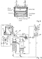
- the separation between the two circuits takes place at the liquid water-superheated steam interface in the tanks R1, R2, this interface being advantageously formed by an insulating element K ( Fig. 9 ) floating on the surface of the water of a tank.
- This insulating element K is for example made of rigid foam. This insulating element during its displacement in its tank is able to give a signal to control the closing of the valve V5, V7 when the liquid level in the reservoir is below a determined level, and / or the closing of the valve V2, V3 when the liquid level in the reservoir considered reaches a predetermined level.
- the insulating element K of the figure 9 has a flat top shape. This makes it possible to make the dead space as small as possible between the insulator K and the face D of the upper bottom of the cylinder R1, R2 figure 9 .
- the tank R1 or R2 is insulated with a thermal insulation layer L, along its inner face.
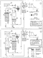
- thermodynamic cycle of the power plant figure 4 is schematized Figures 5 to 8 , but for a power plant having as its source superheated steam a heating element denoted CF at the figure 5 ; this heating body can be conventional (fuel, gas, coal, wood, oil) or solar. It goes without saying that the thermodynamic cycle is similar if the superheated steam is produced by the solar thermal power plant (see figure 10 ) or a combination of solar power station - thermal power plant.
- the superheated high-pressure steam is produced in the heating element or furnace F.
- the superheated steam under high pressure is introduced via the valve V2 into the dead space of the tank R1, dead space located above the insulating element K.
- the valve V3 is in the closed position.
- the tank R1 is intended to supply pressurized water to the Pelton P turbine, while the tank R2 is in the liquid water recharge phase.
- the V2 valve is open to allow the intake of superheated steam from the CF boiler, while the V5 valve is open for the passage of pressurized water to the Pelton P turbine.
- the V1 and V6 valves are closed.
- valve V3 is closed to prevent the passage of superheated steam in the tank R2.
- the valve V7 is also closed to prevent a passage of water from the tank R1 to the tank R2.
- valves V5 and V7 are advantageously associated with a non-return system.
- the valve V4 is opened to allow the expanded vapor still present in the tank R2 to be evacuated and brought to the condenser.
- the valve V8 is also in the open position to allow refilling of the reservoir R2 in liquid water, water that comes from the tank R3, via gravity. This introduction of water into the tank R2 allows the water level to rise and thus to drive the steam out of the tank R2.
- the pressure in the condenser is for example at about 10 5 Pa, the atmospheric pressure.
- the water filling operation of the tank R2 by gravity is advantageously carried out when the vapor pressure present in the tank R2 is reduced, for example close to atmospheric pressure.
- the hot water coming from the condensation of the steam in the condenser C is recovered and sent back to the boiler via the pump P1 and the pipe 24 ( figure 4 ).
- the water of the tank R1 is pressurized, for example at a pressure of 70 10 5 Pa, is fed to one or more injectors I of the Pelton P turbine.
- the turbine P driven in rotation drives an alternator and thus produces electrical energy.
- the tank R1 empties in liquid water.
- the pressure in the tank R1 (which corresponds substantially to the pressure of the water just upstream of the nozzle of the Pelton injector) is represented in the graph of the figure 5 .
- This pressure is first maintained substantially at the pressure Pa of the superheated steam leaving the boiler (phase during which the amount of superheated steam from the boiler keeps the pressure in the tank R1, despite the discharge of water to the turbine between point 1 and point 2 ( figure 5 ), the pressure of the steam is kept constant.
- the valve V2 closes and the pressure of the steam decreases as a function of the volume of water discharged.
- the pressure decreases towards a residual pressure Pb.
- the expansion of the vapor is almost isentropic in the tank R1.
- This residual pressure Pb is for example 2 to 10 10 5 Pa.
- the figure 6 shows the water level in tanks R1 and R2, after partial emptying of R1.
- the water level in the tank R1 is close to the minimum, so that the supply of water from R1 to the turbine P will soon stop, while the water level in the tank R2 is maximum .
- valves V7 and V4 are in the closed position, while the valve V8 is put in the closed position, this closing being followed by the opening of the valve V3 ( figure 7 ) to introduce in the tank R2 superheated steam and increase the pressure in the tank R2.
- the pressure of the water contained in the tank R2 thus increases by a pressure close to atmospheric pressure, at a pressure Pa corresponding substantially to the pressure of the superheated steam.
- the graph of the figure 6 shows the pressure in tank R1, just before closing valve V5.
- the valve V7 is opened so that the pressurized water of the tank R2 moves towards the turbine Pelton P, to drive it in rotation.
- This phase is represented at figure 7 .
- the tank R1 has the valves V2, V5 in the closed position.
- the valve V1 opens to bring the residual pressure steam Pb to the pressure of the steam condenser.
- the valve V6 opens to bring by gravity water into the tank R1 from the tank R3 (collecting the water coming out of the tank). Pelton P turbine).
- the water level in the tank R1 rises, still chasing the steam present in the tank via the valve V1 to the condenser C.
- the level of water in the tank R2 decreases, while the pressure in the tank remains constant during the injection of superheated steam in R2 (see figure 7 ).
- the graph of the figure 7 shows the pressure in the tank R2.
- the power station only comprises a CF thermal power plant, in particular a thermal power plant using wood or wood pellets, or any other fossil fuel, for the production of superheated steam.
- a thermal power plant makes it possible to ensure the production of superheated steam as needed during the day.
- the plant according to the invention can produce powers greater than 50 MW.
- the calories used in the Rankine cycle are those produced by the sun.
- the rated heating element CS can operate alone.
- the figure 10 shows the case of a power plant according to the invention equipped with a conventional heating element, CF noted combustion, paired with a solar heating body noted CS. In the case of figure 10 you can produce energy day and night without getting stuck. It would also be interesting from an ecological point of view to combine concentrated solar energy and the combustion energy of a platelet biomass. of wood, dried hams (eg tomatoes), etc ... figure 10 represents such a central.
- the plant according to the invention is of simple design and can easily be routed and mounted on a site of use.
- the water consumption due to losses can be theoretically zero or in any case extremely reduce.
- the Pelton turbine of the plant according to the invention can use a non-demineralized water unlike the water used in the Rankine cycle with an expansion in a steam turbine.
- the plant according to the invention has also been found to be very low noise, so that it generates little inconvenience for local residents.
Landscapes
- Engineering & Computer Science (AREA)
- Chemical & Material Sciences (AREA)
- Combustion & Propulsion (AREA)
- Mechanical Engineering (AREA)
- General Engineering & Computer Science (AREA)
- Life Sciences & Earth Sciences (AREA)
- Sustainable Development (AREA)
- Sustainable Energy (AREA)
- Engine Equipment That Uses Special Cycles (AREA)
Claims (17)
- Elektrothermie- oder Solarthermie-Kraftwerk, das auf einem thermodynamischen Zyklus, vorzugsweise einem Zyklus, der wenigstens im Wesentlichen zu einem Rankine-Dampfzyklus äquivalent ist, beruht, um eine mit Druck beaufschlagte Flüssigkeit zu erzeugen, das (a) wenigstens eine Pelton-Turbine enthält, um die Energie der mit Druck beaufschlagten Flüssigkeit in mechanische Energie umzuwandeln, und wenigstens einen Generator oder Wechselstromgenerator enthält, um die mechanische Energie in elektrische Energie zu transformieren, wobei das Kraftwerk Folgendes umfasst:(a) eine Einheit (UP) zum Beaufschlagen einer Flüssigkeit mit Druck (Fig. 4),(b) eine Pelton-Turbine (P), die eine Drehwelle besitzt,(c) eine Leitung (20), die die Druckbeaufschlagungseinheit mit der Pelton-Turbine (P) verbindet, um die mit Druck beaufschlagte Flüssigkeit der Pelton-Turbine zuzuführen, wobei die Leitung (20) mit wenigstens einer Einspritzeinrichtung versehen ist, und(d) einen Generator, vorzugsweise einen Wechselstromgenerator, der dafür ausgelegt ist, von der Drehwelle der Turbine (P), vorzugsweise über ein Getriebesystem, angetrieben zu werden,wobei die Einheit (UP) zum Beaufschlagen einer Flüssigkeit mit Druck wenigstens Folgendes umfasst:- einen Vorratsbehälter (R1, R2), der Innendrücken von mehr als 5 · 105 Pa widerstehen kann und dazu bestimmt ist, die mit Druck zu beaufschlagende Flüssigkeit zu enthalten, wobei dem Vorratsbehälter (R1, R2) wenigstens eine erste Ausgangsleitung (14, 14') mit einem Ventil (V5, V7) für die mit Druck beaufschlagte Flüssigkeit in der Leitung (20) und wenigstens eine erste Eingangsleitung (10, 10') mit Ventil (V6, V8), um dem Vorratsbehälter (R1, R2) Flüssigkeit zuzuführen, zugeordnet sind, und- ein Heizmittel,dadurch gekennzeichnet, dass das Heizmittel ein Heizkörper zur Verbrennung fossiler Stoffe, Holzbiomasse oder dergleichen, bezeichnet mit CF, oder ein Heizkörper des Solarkonzentrationstyps oder des Solarthermietyps, mit CS bezeichnet, (Fig. 4 und 10) ist, um den übererhitzten Dampf zu erzeugen,
dass dem Vorratsbehälter (R1, R2) außerdem eine zweite Eingangsleitung (16, 16') zugeordnet ist, um dem Vorratsbehälter (R1, R2) über eine Zufuhrleitung (23), die das System für die Erzeugung von übererhitztem Dampf mit der zweiten Eingangsleitung (16, 16') des Vorratsbehälters verbindet, übererhitzten Dampf zuzuführen, und
dass der eine oder die mehreren Vorratsbehälter (R1, R2) ein isoliertes Schwimmerkolbenelement (K, Fig. 9) umfassen, das auf der Oberfläche der Flüssigkeit, die in dem betrachteten Vorratsbehälter (R1, R2) vorhanden ist, schwimmen kann. - Kraftwerk nach Anspruch 1, dadurch gekennzeichnet, dass das isolierende Element (K) mehr als 90 %, vorzugsweise mehr als 99 % der Oberfläche der Flüssigkeit in dem Vorratsbehälter (R1, R2) abdeckt.
- Kraftwerk nach einem der vorhergehenden Ansprüche, dadurch gekennzeichnet, dass der eine oder die mehreren Vorratsbehälter eine langgestreckte Form haben und dass ihnen ein Schwimmer mit langgestreckter Form zugeordnet ist, der auf der Oberfläche der in dem Vorratsbehälter vorhandenen Flüssigkeit schwimmen kann, wobei der Schwimmer dafür ausgelegt ist, in einem betrachteten Vorratsbehälter einen oberen Teil zu definieren, der dafür ausgelegt ist, im Wesentlichen ausschließlich den übererhitzten Dampf und eventuell Kondensationsflüssigkeit, die von dem übererhitzten Dampf stammt, aufzunehmen, und einen unteren Teil zu definieren, der dafür ausgelegt ist, im Wesentlichen die Flüssigkeit aufzunehmen, die von der Pelton-Turbine stammt, wobei der obere Teil mit wenigstens einer Isolation versehen ist.
- Kraftwerk nach Anspruch 3, dadurch gekennzeichnet, dass der obere Teil und der untere Teil eines Vorratsbehälters unter Einfügung einer Isolierschicht, insbesondere einer isolierenden Membran, deren freier Rand, der in den Innenraum des Vorratsbehälters weist, vorzugsweise dafür ausgelegt ist, die äußere Wand des Schwimmers zu berühren, aneinander befestigt sind.
- Kraftwerk nach einem der vorhergehenden Ansprüche, dadurch gekennzeichnet, dass der eine oder die mehreren Vorratsbehälter (R1, R2) thermisch isoliert sind, vorzugsweise längs ihrer inneren Oberflächen, um eine polytropische oder im Wesentlichen isotropische Entspannung des überhitzten Dampfs sicherzustellen.
- Kraftwerk nach einem der vorhergehenden Ansprüche, dadurch gekennzeichnet, dass dem Vorratsbehälter (R1, R2) außerdem eine zweite Ausgangsleitung (12, 12') zugeordnet ist, um den Dampf, der in dem Vorratsbehälter (R1, R2) vorhanden ist, abzuführen, wobei der zweiten Ausgangsleitung (12, 12') ein Ventil (V1, V4) zugeordnet ist.
- Elektrizitätskraftwerk nach einem der vorhergehenden Ansprüche, dadurch gekennzeichnet, dass es (a) wenigstens einen Satz von 4 Vorratsbehältern, die vorzugsweise im Wesentlichen gleich sind (R1, R2 und R'1 und R'2) sind und dafür ausgelegt ist, den Dampf, der mit einem Druck von mehr als 5 · 105 Pa beaufschlagt ist und der von dem thermodynamischen Zyklus oder von dem Heizkörper (CF) stammt, zu empfangen, und dafür ausgelegt sind, die mit Druck beaufschlagte Flüssigkeit zu enthalten, die für die Pelton-Turbine bestimmt ist, und (b) ein System zum Steuern der Vorratsbehälter, um die mit Druck beaufschlagte Flüssigkeit der Pelton-Turbine zuzufiihren, damit der Generator oder Wechselstromgenerator, der durch die Pelton-Turbine angetrieben wird, elektrische Energie, die über wenigstens 1 Stunde im Wesentlichen stabil ist, erzeugt, umfasst.
- Kraftwerk nach Anspruch 6, dadurch gekennzeichnet, dass die zweite Ausgangsleitung (12, 12') zum Abführen des Dampfs mit einem Kanal (22) verbunden ist, der den Dampf einem Kondensator (C) zuführt, um den entspannten Dampf in Flüssigkeit umzuwandeln, wobei der Kondensator (C) durch einen Kanal (24) verbunden ist, der ein Pumpmittel (P1) enthält, um Flüssigkeit, die der Kondensation stammt, von dem Druck des Kondensators auf den maximalem Druck in dem System (CS, CF) zu bringen, um den übererhitzten Dampf zu erzeugen.
- Kraftwerk nach einem der vorhergehenden Ansprüche, dadurch gekennzeichnet, dass es wenigstens einen ersten Vorratsbehälter (R1) und einen zweiten Vorratsbehälter (R2), die parallel geschaltet sind, umfasst, wobei sowohl der erste als auch der zweite Vorratsbehälter (R1, R2) dafür ausgelegt sind, Innendrücken von mehr als 5 · 105 Pa zu widerstehen, und dafür bestimmt sind, die mit Druck zu beaufschlagende Flüssigkeit zu enthalten, wobei jedem Vorratsbehälter (R1, R2) wenigstens eine erste Ausgangsleitung (14, 14') mit einem Ventil (V5, V7) für die mit Druck beaufschlagte Flüssigkeit in dem Vorratsbehälter und eine zweite Ausgangsleitung (12, 12'), um den Dampf, der in dem betrachteten Vorratsbehälter vorhanden ist, abzuführen, zugeordnet sind, wobei der zweiten Ausgangsleitung (12, 12') ein Ventil (V1, V4), eine erste Eingangsleitung (10, 10') mit Ventil (V6, V8), um dem betrachteten Vorratsbehälter (R1, R2) Flüssigkeit zuzuführen, und eine zweite Eingangsleitung (16, 16'), um dem betrachteten Vorratsbehälter (R1, R2) übererhitzten Dampf zuzuführen, zugeordnet sind.
- Kraftwerk nach einem der vorhergehenden Ansprüche, dadurch gekennzeichnet, dass es wenigstens einen Sammler (FR) umfasst, der dafür ausgelegt ist, Flüssigkeit nach ihrer Wirkung in der Pelton-Turbine (P) wiederzugewinnen, wobei der Flüssigkeitssammler (FR von R3) in Bezug auf einen oder mehrere Vorratsbehälter (R1, R2) im Wesentlichen erhöht ist, um eine Befüllung des einen oder der mehreren betrachteten Vorratsbehälter (R1, R2) durch die Schwerkraft durch einen Kanal (21), der sich zwischen dem Sammler (FR) und der ersten Eingangsleitung (10, 10') des einen oder der mehreren betrachteten Vorratsbehälter erstreckt, zu ermöglichen, derart, dass ein erster geschlossener Kreis für die Flüssigkeit zwischen der Pelton-Turbine (P) und dem einen oder den mehreren Vorratsbehältern (R1 oder R2) gebildet ist.
- Kraftwerk nach Anspruch 8, dadurch gekennzeichnet, dass das System (CS, CF) für die Erzeugung des übererhitzten Dampfs und der eine oder die mehreren Vorratsbehälter (R1, R2) einen zweiten geschlossenen Kreis mit dem Kondensator (C) und dem Pumpsystem (P1) bilden.
- Elektrothermie-Kraftwerk nach einem der vorhergehenden Ansprüche, dadurch gekennzeichnet, dass es eine Reihe von gepaarten Vorratsbehältern (R1, R2) umfasst, die dafür ausgelegt sind, eine Reihe von Pelton-Turbinen (P) zu versorgen, wovon jede für eine Leistung in der optimalen Umgebung ausgelegt ist und deren Wellen vorzugsweise über einen Getriebezug denselben Generator, vorzugsweise denselben Wechselstromgenerator, antreiben.
- Elektrothermie-Kraftwerk nach einem der vorhergehenden Ansprüche, dadurch gekennzeichnet, dass die Flüssigkeit ein wässriges Medium ist, das vorzugsweise mehr als 90 Gew.-% Wasser enthält, während der übererhitzte Dampf ein Dampf ist, der aus mehr als 90 Vol.-% übererhitztem Wasserdampf unter Druck gebildet ist.
- Elektrothermie-Kraftwerk nach Anspruch 1, dadurch gekennzeichnet, dass es einen Kondensator (C) für Dampf, der aus einem oder mehreren Vorratsbehältern (R1, R2) austritt, umfasst, wobei der Kondensator (C) ein Wärmetauscherelement umfasst, in dem ein Fluid zirkuliert, um die Kondensation des Dampfes in eine Flüssigkeit sicherzustellen, und dass das Wärmetauscherelement des Kondensators (C) mit einem Tauscher verbunden ist, der ermöglicht, die Kondensationswärme für eine Doppelgenerationsanwendung zu verwenden.
- Elektrothermie-Kraftwerk nach einem der vorhergehenden Ansprüche, dadurch gekennzeichnet, dass es dafür ausgelegt ist, mit Drücken von übererhitztem Dampf von mehr als 10 · 105 Pa, vorzugsweise mehr als 25 · 105 Pa, bevorzugt mehr als 50 · 105 Pa oder mehr bei Dampftemperaturen im Bereich von 110 °C bis 600 °C, insbesondere mehr als 150 °C, zu arbeiten.
- Verfahren zum Erzeugen elektrischer Energie unter Verwendung eines Kraftwerks nach einem der Ansprüche 1 bis 15, wobei:- übererhitzter Dampf, vorzugsweise übererhitzter Wasserdampf, erzeugt wird;- dieser übererhitzte Dampf einem Vorratsbehälter zugeführt wird, der eine Flüssigkeit enthält, um sie mit Druck zu beaufschlagen, und- die mit Druck beaufschlagte Flüssigkeit zu wenigstens einer Pelton-Turbine geleitet wird, um wenigstens einen Generator oder Wechselstromgenerator anzutreiben, um elektrische Energie zu erzeugen.
- Verfahren nach Anspruch 16, wobei wenigstens ein Satz im Wesentlichen gleicher Vorratsbehälter (R1, R2 und R'1 und R'2) verwendet wird, um eine Flüssigkeit mittels übererhitzten Dampfs mit Druck zu beaufschlagen, und wobei der Befüllungs- und Entleerungszyklus eines Paars Vorratsbehälter (R1, R2) und jener eines anderen Paars Vorratsbehälter (R'1, R'2) versetzt kombiniert werden, derart, dass die Lieferung von Dampf unter Druck, der von dem Wasserkessel stammt, ununterbrochen ohne Abweichung gesteuert wird.
Applications Claiming Priority (2)
| Application Number | Priority Date | Filing Date | Title |
|---|---|---|---|
| BE2012/0874A BE1021499B1 (fr) | 2012-12-21 | 2012-12-21 | Centrale electrique thermique classique ou solaire thermodynamique a concentration |
| PCT/BE2013/000066 WO2014094079A1 (fr) | 2012-12-21 | 2013-12-17 | Centrale électrique thermique classique ou solaire thermodynamique à concentration |
Publications (2)
| Publication Number | Publication Date |
|---|---|
| EP2935807A1 EP2935807A1 (de) | 2015-10-28 |
| EP2935807B1 true EP2935807B1 (de) | 2017-05-10 |
Family
ID=47754239
Family Applications (1)
| Application Number | Title | Priority Date | Filing Date |
|---|---|---|---|
| EP13826989.9A Active EP2935807B1 (de) | 2012-12-21 | 2013-12-17 | Konzentrierendes thermodynamisches solar- oder konventionelles wärmekraftwerk |
Country Status (5)
| Country | Link |
|---|---|
| US (1) | US9540943B2 (de) |
| EP (1) | EP2935807B1 (de) |
| JP (1) | JP6298072B2 (de) |
| BE (1) | BE1021499B1 (de) |
| WO (1) | WO2014094079A1 (de) |
Families Citing this family (12)
| Publication number | Priority date | Publication date | Assignee | Title |
|---|---|---|---|---|
| US20170175672A1 (en) * | 2014-03-04 | 2017-06-22 | Wave Solar Llc | Liquid piston engine |
| JP2016023552A (ja) * | 2014-07-16 | 2016-02-08 | 株式会社前川製作所 | 複合ランキンサイクルを用いた排熱回収装置 |
| FR3034133B1 (fr) * | 2015-03-25 | 2017-04-28 | Madhav Rathour | Dispositif de production d'energie electrique |
| JP6762374B2 (ja) * | 2016-04-29 | 2020-09-30 | スピラックス‐サルコ リミテッド | ポンプ装置 |
| US9745867B1 (en) * | 2016-07-25 | 2017-08-29 | Loren R. Eastland | Compound energy co-generation system |
| PL418192A1 (pl) * | 2016-08-03 | 2018-02-12 | Józef Kowalczyk | Sposób zamiany energii cieplnej na energię mechaniczną oraz konwerter termo-hydro-dynamiczny |
| MA51537B1 (fr) * | 2020-10-19 | 2022-10-31 | Byah Ahmed | Convertisseur d'énergie calorifique stockée dans les eaux des océans et dans l'atmosphère en énergie électrique. |
| US11761355B2 (en) * | 2021-09-29 | 2023-09-19 | Linden Noble | Vapor-powered liquid-driven turbine |
| FR3138168A1 (fr) * | 2022-07-25 | 2024-01-26 | Pierre Lecanu | Centrale Hydro-solaire-vapeur-électrique |
| WO2024047380A1 (en) * | 2022-08-31 | 2024-03-07 | Karahan Ahmet | Micro electrical power generation from external combustion heat energy, using pressure swing on hot-oil liquid pistons (pslp) |
| CN116007234A (zh) * | 2023-01-10 | 2023-04-25 | 西安热工研究院有限公司 | 一种可相变蒸汽压缩式热泵及其工作方法 |
| US12158097B2 (en) * | 2023-03-30 | 2024-12-03 | Fca Us Llc | Thermal accumulator assembly |
Family Cites Families (18)
| Publication number | Priority date | Publication date | Assignee | Title |
|---|---|---|---|---|
| US3611723A (en) * | 1969-11-13 | 1971-10-12 | Hollymatic Corp | Hydraulic turbine and method |
| US4063417A (en) * | 1976-02-04 | 1977-12-20 | Carrier Corporation | Power generating system employing geothermally heated fluid |
| IT1130639B (it) * | 1980-05-21 | 1986-06-18 | Bruno Scalfi | Struttura di caldaia a rendimento ottimizzato |
| US4710100A (en) | 1983-11-21 | 1987-12-01 | Oliver Laing | Wind machine |
| US5247796A (en) * | 1985-12-27 | 1993-09-28 | Parker Robin Z | Solar augmented power system |
| US5461858A (en) * | 1994-04-04 | 1995-10-31 | Energy Conversation Partnership, Ltd. | Method of producing hydroelectric power |
| GB9522231D0 (en) * | 1995-10-31 | 1996-01-03 | Dantec Services Ltd | Method and apparatus for driving a rotor |
| JPH09222003A (ja) * | 1996-02-19 | 1997-08-26 | Isao Nihei | 熱エネルギーを動力に変換する方法 |
| US20090179429A1 (en) * | 2007-11-09 | 2009-07-16 | Erik Ellis | Efficient low temperature thermal energy storage |
| AT506796B1 (de) * | 2008-11-19 | 2009-12-15 | Imt C Innovative Motorfahrzeug | Verfahren zum betreiben einer wärmekraftmaschine sowie wärmekraftmaschine zur durchführung des verfahrens |
| ES2350221B1 (es) * | 2009-06-19 | 2011-10-21 | Abengoa Solar New Technologies, S.A. | Sistema y procedimiento de acumulacion de vapor en tanques para aplicacion solar. |
| US8495872B2 (en) * | 2010-08-20 | 2013-07-30 | Sustainx, Inc. | Energy storage and recovery utilizing low-pressure thermal conditioning for heat exchange with high-pressure gas |
| WO2012120556A1 (ja) * | 2011-03-07 | 2012-09-13 | 株式会社 日立製作所 | 太陽熱蒸気サイクルシステム |
| MX2013011351A (es) * | 2011-04-01 | 2014-05-14 | Nuovo Pignone Spa | Ciclo de rankine organico para un sistema de energia solar concentrada. |
| US20120291433A1 (en) * | 2011-05-19 | 2012-11-22 | Ning Meng | Low temperature rankine cycle solar power system with low critical temperature hfc or hc working fluid |
| WO2013000013A1 (en) * | 2011-06-27 | 2013-01-03 | Newcastle Innovation Limited | Geothermal assisted power generation |
| ES2482940B1 (es) * | 2011-08-30 | 2015-07-07 | Abengoa Solar Llc | Campo solar híbrido. |
| US9341165B2 (en) * | 2012-12-20 | 2016-05-17 | Howard G. Hoose, JR. | Power generation system and method of use thereof |
-
2012
- 2012-12-21 BE BE2012/0874A patent/BE1021499B1/fr not_active IP Right Cessation
-
2013
- 2013-12-17 EP EP13826989.9A patent/EP2935807B1/de active Active
- 2013-12-17 JP JP2015548113A patent/JP6298072B2/ja active Active
- 2013-12-17 WO PCT/BE2013/000066 patent/WO2014094079A1/fr not_active Ceased
-
2015
- 2015-06-19 US US14/744,687 patent/US9540943B2/en active Active
Also Published As
| Publication number | Publication date |
|---|---|
| BE1021499B1 (fr) | 2015-12-03 |
| EP2935807A1 (de) | 2015-10-28 |
| JP6298072B2 (ja) | 2018-03-20 |
| WO2014094079A1 (fr) | 2014-06-26 |
| JP2016504521A (ja) | 2016-02-12 |
| US9540943B2 (en) | 2017-01-10 |
| US20150354398A1 (en) | 2015-12-10 |
Similar Documents
| Publication | Publication Date | Title |
|---|---|---|
| BE1021499B1 (fr) | Centrale electrique thermique classique ou solaire thermodynamique a concentration | |
| EP2659098B1 (de) | Vorrichtung zur umwandlung von wärmeenergie in mechanische energie | |
| JP5486739B2 (ja) | バイオマスボイラを補助熱源として使用する太陽光発電方法およびシステム | |
| EP2379848B1 (de) | Elektrizitätserzeugungsvorrichtung mit mehreren wärmepumpen in reihe | |
| EP3303825B1 (de) | Vorrichtung und verfahren zur umwandlung und speicherung elektrischer energie in form von druckluft | |
| FR3016025A1 (fr) | Combinaison d'une unite de stockage d'energie par air comprime et d'une centrale thermique | |
| FR3034813A1 (fr) | Systeme et procede de stockage et de recuperation d'energie par air comprime avec chauffage a volume constant | |
| EP2427656A2 (de) | Verfahren und vorrichtung zum speichern von mechanischer energie durch die quasi-isotherme entspannung und komprimierung eines gases | |
| EP1764494A1 (de) | Anlage zur Speicherung und Rückgewinnung von elektrischer Energie | |
| WO2014080130A1 (fr) | Groupe de conversion d'une energie thermique en une energie hydraulique | |
| FR2864174A1 (fr) | Centrale electrique mobile, utilisant l'air comprime pour stocker l'energie puis l'action de la poussee d'archimede sur une roue pour sa recuperation | |
| FR3025593A1 (fr) | La tour solaire hydroelectrique a concentration ponctuelle | |
| WO2022086312A1 (fr) | Convertisseur d'énergie calorifique d' origine solaire stockée dans les eaux des océans et dans l'atmosphère en énergie électrique. | |
| FR2983246A1 (fr) | Installation de stockage et de restitution d'energie sous forme de gaz comprime isobare et procede de stockage et de restitution d'energie correspondant | |
| JP7777749B2 (ja) | 蒸発若しくは昇華および凝縮に浮力ファクターを用いた熱エネルギからの機械的/電気的エネルギの生成 | |
| TW202012768A (zh) | 用蒸發、昇華和冷凝和浮力係數從熱能中產生機械/電能 | |
| FR2696506A1 (fr) | Centrale combinée hydraulique et thermique pour production simultanée de l'électricité et d'énergie calorifique. | |
| FR2964693A1 (fr) | Installation de restitution d'energie | |
| FR3112601A1 (fr) | Procédé et système pour le stockage thermomécanique d’énergie | |
| FR3003600A1 (fr) | Systeme mecanique reversible de production de gaz liquefie ou d’energie mecanique | |
| EP2399024A2 (de) | System und verfahren zur autonomen erzeugung von fluid und elektrizität | |
| FR2729717A1 (fr) | Installation motrice | |
| FR3093168A1 (fr) | Dispositif thermovoltäique progressif multi-sources avec capacités de stockage d'énergie, et procédés associés. | |
| GB2572806A (en) | Pneumatic electric power system | |
| WO2000070212A1 (fr) | Centrale de generation d'energie electrique comportant des moyens turbo alternateurs |
Legal Events
| Date | Code | Title | Description |
|---|---|---|---|
| PUAI | Public reference made under article 153(3) epc to a published international application that has entered the european phase |
Free format text: ORIGINAL CODE: 0009012 |
|
| 17P | Request for examination filed |
Effective date: 20150713 |
|
| AK | Designated contracting states |
Kind code of ref document: A1 Designated state(s): AL AT BE BG CH CY CZ DE DK EE ES FI FR GB GR HR HU IE IS IT LI LT LU LV MC MK MT NL NO PL PT RO RS SE SI SK SM TR |
|
| AX | Request for extension of the european patent |
Extension state: BA ME |
|
| DAX | Request for extension of the european patent (deleted) | ||
| REG | Reference to a national code |
Ref country code: DE Ref legal event code: R079 Ref document number: 602013021071 Country of ref document: DE Free format text: PREVIOUS MAIN CLASS: F01K0027000000 Ipc: F01D0015100000 |
|
| GRAP | Despatch of communication of intention to grant a patent |
Free format text: ORIGINAL CODE: EPIDOSNIGR1 |
|
| RIC1 | Information provided on ipc code assigned before grant |
Ipc: F02G 5/02 20060101ALI20161130BHEP Ipc: F01K 3/00 20060101ALI20161130BHEP Ipc: F01K 27/00 20060101ALI20161130BHEP Ipc: F03G 6/06 20060101ALI20161130BHEP Ipc: F01K 1/12 20060101ALI20161130BHEP Ipc: F01D 15/10 20060101AFI20161130BHEP |
|
| INTG | Intention to grant announced |
Effective date: 20161221 |
|
| GRAS | Grant fee paid |
Free format text: ORIGINAL CODE: EPIDOSNIGR3 |
|
| GRAA | (expected) grant |
Free format text: ORIGINAL CODE: 0009210 |
|
| AK | Designated contracting states |
Kind code of ref document: B1 Designated state(s): AL AT BE BG CH CY CZ DE DK EE ES FI FR GB GR HR HU IE IS IT LI LT LU LV MC MK MT NL NO PL PT RO RS SE SI SK SM TR |
|
| REG | Reference to a national code |
Ref country code: GB Ref legal event code: FG4D Free format text: NOT ENGLISH |
|
| REG | Reference to a national code |
Ref country code: AT Ref legal event code: REF Ref document number: 892559 Country of ref document: AT Kind code of ref document: T Effective date: 20170515 Ref country code: CH Ref legal event code: EP |
|
| REG | Reference to a national code |
Ref country code: IE Ref legal event code: FG4D Free format text: LANGUAGE OF EP DOCUMENT: FRENCH |
|
| REG | Reference to a national code |
Ref country code: DE Ref legal event code: R096 Ref document number: 602013021071 Country of ref document: DE |
|
| REG | Reference to a national code |
Ref country code: SE Ref legal event code: TRGR |
|
| REG | Reference to a national code |
Ref country code: NL Ref legal event code: MP Effective date: 20170510 |
|
| REG | Reference to a national code |
Ref country code: LT Ref legal event code: MG4D |
|
| REG | Reference to a national code |
Ref country code: AT Ref legal event code: MK05 Ref document number: 892559 Country of ref document: AT Kind code of ref document: T Effective date: 20170510 |
|
| PG25 | Lapsed in a contracting state [announced via postgrant information from national office to epo] |
Ref country code: LT Free format text: LAPSE BECAUSE OF FAILURE TO SUBMIT A TRANSLATION OF THE DESCRIPTION OR TO PAY THE FEE WITHIN THE PRESCRIBED TIME-LIMIT Effective date: 20170510 Ref country code: HR Free format text: LAPSE BECAUSE OF FAILURE TO SUBMIT A TRANSLATION OF THE DESCRIPTION OR TO PAY THE FEE WITHIN THE PRESCRIBED TIME-LIMIT Effective date: 20170510 Ref country code: NO Free format text: LAPSE BECAUSE OF FAILURE TO SUBMIT A TRANSLATION OF THE DESCRIPTION OR TO PAY THE FEE WITHIN THE PRESCRIBED TIME-LIMIT Effective date: 20170810 Ref country code: GR Free format text: LAPSE BECAUSE OF FAILURE TO SUBMIT A TRANSLATION OF THE DESCRIPTION OR TO PAY THE FEE WITHIN THE PRESCRIBED TIME-LIMIT Effective date: 20170811 Ref country code: ES Free format text: LAPSE BECAUSE OF FAILURE TO SUBMIT A TRANSLATION OF THE DESCRIPTION OR TO PAY THE FEE WITHIN THE PRESCRIBED TIME-LIMIT Effective date: 20170510 Ref country code: FI Free format text: LAPSE BECAUSE OF FAILURE TO SUBMIT A TRANSLATION OF THE DESCRIPTION OR TO PAY THE FEE WITHIN THE PRESCRIBED TIME-LIMIT Effective date: 20170510 Ref country code: AT Free format text: LAPSE BECAUSE OF FAILURE TO SUBMIT A TRANSLATION OF THE DESCRIPTION OR TO PAY THE FEE WITHIN THE PRESCRIBED TIME-LIMIT Effective date: 20170510 |
|
| PG25 | Lapsed in a contracting state [announced via postgrant information from national office to epo] |
Ref country code: NL Free format text: LAPSE BECAUSE OF FAILURE TO SUBMIT A TRANSLATION OF THE DESCRIPTION OR TO PAY THE FEE WITHIN THE PRESCRIBED TIME-LIMIT Effective date: 20170510 Ref country code: BG Free format text: LAPSE BECAUSE OF FAILURE TO SUBMIT A TRANSLATION OF THE DESCRIPTION OR TO PAY THE FEE WITHIN THE PRESCRIBED TIME-LIMIT Effective date: 20170810 Ref country code: IS Free format text: LAPSE BECAUSE OF FAILURE TO SUBMIT A TRANSLATION OF THE DESCRIPTION OR TO PAY THE FEE WITHIN THE PRESCRIBED TIME-LIMIT Effective date: 20170910 Ref country code: PL Free format text: LAPSE BECAUSE OF FAILURE TO SUBMIT A TRANSLATION OF THE DESCRIPTION OR TO PAY THE FEE WITHIN THE PRESCRIBED TIME-LIMIT Effective date: 20170510 Ref country code: RS Free format text: LAPSE BECAUSE OF FAILURE TO SUBMIT A TRANSLATION OF THE DESCRIPTION OR TO PAY THE FEE WITHIN THE PRESCRIBED TIME-LIMIT Effective date: 20170510 Ref country code: LV Free format text: LAPSE BECAUSE OF FAILURE TO SUBMIT A TRANSLATION OF THE DESCRIPTION OR TO PAY THE FEE WITHIN THE PRESCRIBED TIME-LIMIT Effective date: 20170510 |
|
| REG | Reference to a national code |
Ref country code: FR Ref legal event code: PLFP Year of fee payment: 5 |
|
| PG25 | Lapsed in a contracting state [announced via postgrant information from national office to epo] |
Ref country code: SK Free format text: LAPSE BECAUSE OF FAILURE TO SUBMIT A TRANSLATION OF THE DESCRIPTION OR TO PAY THE FEE WITHIN THE PRESCRIBED TIME-LIMIT Effective date: 20170510 Ref country code: DK Free format text: LAPSE BECAUSE OF FAILURE TO SUBMIT A TRANSLATION OF THE DESCRIPTION OR TO PAY THE FEE WITHIN THE PRESCRIBED TIME-LIMIT Effective date: 20170510 Ref country code: CZ Free format text: LAPSE BECAUSE OF FAILURE TO SUBMIT A TRANSLATION OF THE DESCRIPTION OR TO PAY THE FEE WITHIN THE PRESCRIBED TIME-LIMIT Effective date: 20170510 Ref country code: EE Free format text: LAPSE BECAUSE OF FAILURE TO SUBMIT A TRANSLATION OF THE DESCRIPTION OR TO PAY THE FEE WITHIN THE PRESCRIBED TIME-LIMIT Effective date: 20170510 Ref country code: RO Free format text: LAPSE BECAUSE OF FAILURE TO SUBMIT A TRANSLATION OF THE DESCRIPTION OR TO PAY THE FEE WITHIN THE PRESCRIBED TIME-LIMIT Effective date: 20170510 |
|
| REG | Reference to a national code |
Ref country code: DE Ref legal event code: R097 Ref document number: 602013021071 Country of ref document: DE |
|
| PG25 | Lapsed in a contracting state [announced via postgrant information from national office to epo] |
Ref country code: IT Free format text: LAPSE BECAUSE OF FAILURE TO SUBMIT A TRANSLATION OF THE DESCRIPTION OR TO PAY THE FEE WITHIN THE PRESCRIBED TIME-LIMIT Effective date: 20170510 Ref country code: SM Free format text: LAPSE BECAUSE OF FAILURE TO SUBMIT A TRANSLATION OF THE DESCRIPTION OR TO PAY THE FEE WITHIN THE PRESCRIBED TIME-LIMIT Effective date: 20170510 |
|
| PLBE | No opposition filed within time limit |
Free format text: ORIGINAL CODE: 0009261 |
|
| STAA | Information on the status of an ep patent application or granted ep patent |
Free format text: STATUS: NO OPPOSITION FILED WITHIN TIME LIMIT |
|
| 26N | No opposition filed |
Effective date: 20180213 |
|
| PG25 | Lapsed in a contracting state [announced via postgrant information from national office to epo] |
Ref country code: SI Free format text: LAPSE BECAUSE OF FAILURE TO SUBMIT A TRANSLATION OF THE DESCRIPTION OR TO PAY THE FEE WITHIN THE PRESCRIBED TIME-LIMIT Effective date: 20170510 |
|
| REG | Reference to a national code |
Ref country code: CH Ref legal event code: PL |
|
| GBPC | Gb: european patent ceased through non-payment of renewal fee |
Effective date: 20171217 |
|
| REG | Reference to a national code |
Ref country code: IE Ref legal event code: MM4A |
|
| PG25 | Lapsed in a contracting state [announced via postgrant information from national office to epo] |
Ref country code: LU Free format text: LAPSE BECAUSE OF NON-PAYMENT OF DUE FEES Effective date: 20171217 Ref country code: MT Free format text: LAPSE BECAUSE OF FAILURE TO SUBMIT A TRANSLATION OF THE DESCRIPTION OR TO PAY THE FEE WITHIN THE PRESCRIBED TIME-LIMIT Effective date: 20170510 |
|
| PG25 | Lapsed in a contracting state [announced via postgrant information from national office to epo] |
Ref country code: IE Free format text: LAPSE BECAUSE OF NON-PAYMENT OF DUE FEES Effective date: 20171217 |
|
| PG25 | Lapsed in a contracting state [announced via postgrant information from national office to epo] |
Ref country code: LI Free format text: LAPSE BECAUSE OF NON-PAYMENT OF DUE FEES Effective date: 20171231 Ref country code: GB Free format text: LAPSE BECAUSE OF NON-PAYMENT OF DUE FEES Effective date: 20171217 Ref country code: CH Free format text: LAPSE BECAUSE OF NON-PAYMENT OF DUE FEES Effective date: 20171231 |
|
| PG25 | Lapsed in a contracting state [announced via postgrant information from national office to epo] |
Ref country code: HU Free format text: LAPSE BECAUSE OF FAILURE TO SUBMIT A TRANSLATION OF THE DESCRIPTION OR TO PAY THE FEE WITHIN THE PRESCRIBED TIME-LIMIT; INVALID AB INITIO Effective date: 20131217 Ref country code: MC Free format text: LAPSE BECAUSE OF FAILURE TO SUBMIT A TRANSLATION OF THE DESCRIPTION OR TO PAY THE FEE WITHIN THE PRESCRIBED TIME-LIMIT Effective date: 20170510 |
|
| PG25 | Lapsed in a contracting state [announced via postgrant information from national office to epo] |
Ref country code: CY Free format text: LAPSE BECAUSE OF FAILURE TO SUBMIT A TRANSLATION OF THE DESCRIPTION OR TO PAY THE FEE WITHIN THE PRESCRIBED TIME-LIMIT Effective date: 20170510 |
|
| PG25 | Lapsed in a contracting state [announced via postgrant information from national office to epo] |
Ref country code: MK Free format text: LAPSE BECAUSE OF FAILURE TO SUBMIT A TRANSLATION OF THE DESCRIPTION OR TO PAY THE FEE WITHIN THE PRESCRIBED TIME-LIMIT Effective date: 20170510 |
|
| PG25 | Lapsed in a contracting state [announced via postgrant information from national office to epo] |
Ref country code: TR Free format text: LAPSE BECAUSE OF FAILURE TO SUBMIT A TRANSLATION OF THE DESCRIPTION OR TO PAY THE FEE WITHIN THE PRESCRIBED TIME-LIMIT Effective date: 20170510 |
|
| PG25 | Lapsed in a contracting state [announced via postgrant information from national office to epo] |
Ref country code: PT Free format text: LAPSE BECAUSE OF FAILURE TO SUBMIT A TRANSLATION OF THE DESCRIPTION OR TO PAY THE FEE WITHIN THE PRESCRIBED TIME-LIMIT Effective date: 20170510 |
|
| PG25 | Lapsed in a contracting state [announced via postgrant information from national office to epo] |
Ref country code: AL Free format text: LAPSE BECAUSE OF FAILURE TO SUBMIT A TRANSLATION OF THE DESCRIPTION OR TO PAY THE FEE WITHIN THE PRESCRIBED TIME-LIMIT Effective date: 20170510 |
|
| PGFP | Annual fee paid to national office [announced via postgrant information from national office to epo] |
Ref country code: FR Payment date: 20251209 Year of fee payment: 13 |
|
| PGFP | Annual fee paid to national office [announced via postgrant information from national office to epo] |
Ref country code: BE Payment date: 20251127 Year of fee payment: 13 |
|
| PGFP | Annual fee paid to national office [announced via postgrant information from national office to epo] |
Ref country code: SE Payment date: 20251219 Year of fee payment: 13 |
|
| PGFP | Annual fee paid to national office [announced via postgrant information from national office to epo] |
Ref country code: DE Payment date: 20251223 Year of fee payment: 13 |