EP2935822B1 - Système de refroidissement dans un véhicule - Google Patents
Système de refroidissement dans un véhicule Download PDFInfo
- Publication number
- EP2935822B1 EP2935822B1 EP13864357.2A EP13864357A EP2935822B1 EP 2935822 B1 EP2935822 B1 EP 2935822B1 EP 13864357 A EP13864357 A EP 13864357A EP 2935822 B1 EP2935822 B1 EP 2935822B1
- Authority
- EP
- European Patent Office
- Prior art keywords
- cooling fluid
- cooling
- line
- cooling system
- condition
- Prior art date
- Legal status (The legal status is an assumption and is not a legal conclusion. Google has not performed a legal analysis and makes no representation as to the accuracy of the status listed.)
- Active
Links
Images
Classifications
-
- F—MECHANICAL ENGINEERING; LIGHTING; HEATING; WEAPONS; BLASTING
- F16—ENGINEERING ELEMENTS AND UNITS; GENERAL MEASURES FOR PRODUCING AND MAINTAINING EFFECTIVE FUNCTIONING OF MACHINES OR INSTALLATIONS; THERMAL INSULATION IN GENERAL
- F16D—COUPLINGS FOR TRANSMITTING ROTATION; CLUTCHES; BRAKES
- F16D57/00—Liquid-resistance brakes; Brakes using the internal friction of fluids or fluid-like media, e.g. powders
-
- G—PHYSICS
- G05—CONTROLLING; REGULATING
- G05D—SYSTEMS FOR CONTROLLING OR REGULATING NON-ELECTRIC VARIABLES
- G05D23/00—Control of temperature
- G05D23/01—Control of temperature without auxiliary power
- G05D23/02—Control of temperature without auxiliary power with sensing element expanding and contracting in response to changes of temperature
- G05D23/021—Control of temperature without auxiliary power with sensing element expanding and contracting in response to changes of temperature the sensing element being a non-metallic solid, e.g. elastomer, paste
- G05D23/023—Control of temperature without auxiliary power with sensing element expanding and contracting in response to changes of temperature the sensing element being a non-metallic solid, e.g. elastomer, paste the sensing element being placed outside a regulating fluid flow
-
- B—PERFORMING OPERATIONS; TRANSPORTING
- B60—VEHICLES IN GENERAL
- B60T—VEHICLE BRAKE CONTROL SYSTEMS OR PARTS THEREOF; BRAKE CONTROL SYSTEMS OR PARTS THEREOF, IN GENERAL; ARRANGEMENT OF BRAKING ELEMENTS ON VEHICLES IN GENERAL; PORTABLE DEVICES FOR PREVENTING UNWANTED MOVEMENT OF VEHICLES; VEHICLE MODIFICATIONS TO FACILITATE COOLING OF BRAKES
- B60T1/00—Arrangements of braking elements, i.e. of those parts where braking effect occurs specially for vehicles
- B60T1/02—Arrangements of braking elements, i.e. of those parts where braking effect occurs specially for vehicles acting by retarding wheels
- B60T1/08—Arrangements of braking elements, i.e. of those parts where braking effect occurs specially for vehicles acting by retarding wheels using fluid or powdered medium
- B60T1/087—Arrangements of braking elements, i.e. of those parts where braking effect occurs specially for vehicles acting by retarding wheels using fluid or powdered medium in hydrodynamic, i.e. non-positive displacement, retarders
-
- B—PERFORMING OPERATIONS; TRANSPORTING
- B60—VEHICLES IN GENERAL
- B60T—VEHICLE BRAKE CONTROL SYSTEMS OR PARTS THEREOF; BRAKE CONTROL SYSTEMS OR PARTS THEREOF, IN GENERAL; ARRANGEMENT OF BRAKING ELEMENTS ON VEHICLES IN GENERAL; PORTABLE DEVICES FOR PREVENTING UNWANTED MOVEMENT OF VEHICLES; VEHICLE MODIFICATIONS TO FACILITATE COOLING OF BRAKES
- B60T10/00—Control or regulation for continuous braking making use of fluid or powdered medium, e.g. for use when descending a long slope
- B60T10/02—Control or regulation for continuous braking making use of fluid or powdered medium, e.g. for use when descending a long slope with hydrodynamic brake
-
- B—PERFORMING OPERATIONS; TRANSPORTING
- B60—VEHICLES IN GENERAL
- B60T—VEHICLE BRAKE CONTROL SYSTEMS OR PARTS THEREOF; BRAKE CONTROL SYSTEMS OR PARTS THEREOF, IN GENERAL; ARRANGEMENT OF BRAKING ELEMENTS ON VEHICLES IN GENERAL; PORTABLE DEVICES FOR PREVENTING UNWANTED MOVEMENT OF VEHICLES; VEHICLE MODIFICATIONS TO FACILITATE COOLING OF BRAKES
- B60T5/00—Vehicle modifications to facilitate cooling of brakes
-
- F—MECHANICAL ENGINEERING; LIGHTING; HEATING; WEAPONS; BLASTING
- F01—MACHINES OR ENGINES IN GENERAL; ENGINE PLANTS IN GENERAL; STEAM ENGINES
- F01P—COOLING OF MACHINES OR ENGINES IN GENERAL; COOLING OF INTERNAL-COMBUSTION ENGINES
- F01P3/00—Liquid cooling
- F01P3/12—Arrangements for cooling other engine or machine parts
-
- F—MECHANICAL ENGINEERING; LIGHTING; HEATING; WEAPONS; BLASTING
- F01—MACHINES OR ENGINES IN GENERAL; ENGINE PLANTS IN GENERAL; STEAM ENGINES
- F01P—COOLING OF MACHINES OR ENGINES IN GENERAL; COOLING OF INTERNAL-COMBUSTION ENGINES
- F01P3/00—Liquid cooling
- F01P3/20—Cooling circuits not specific to a single part of engine or machine
-
- F—MECHANICAL ENGINEERING; LIGHTING; HEATING; WEAPONS; BLASTING
- F01—MACHINES OR ENGINES IN GENERAL; ENGINE PLANTS IN GENERAL; STEAM ENGINES
- F01P—COOLING OF MACHINES OR ENGINES IN GENERAL; COOLING OF INTERNAL-COMBUSTION ENGINES
- F01P7/00—Controlling of coolant flow
- F01P7/14—Controlling of coolant flow the coolant being liquid
- F01P7/16—Controlling of coolant flow the coolant being liquid by thermostatic control
- F01P7/165—Controlling of coolant flow the coolant being liquid by thermostatic control characterised by systems with two or more loops
-
- G—PHYSICS
- G05—CONTROLLING; REGULATING
- G05D—SYSTEMS FOR CONTROLLING OR REGULATING NON-ELECTRIC VARIABLES
- G05D23/00—Control of temperature
- G05D23/01—Control of temperature without auxiliary power
- G05D23/02—Control of temperature without auxiliary power with sensing element expanding and contracting in response to changes of temperature
- G05D23/021—Control of temperature without auxiliary power with sensing element expanding and contracting in response to changes of temperature the sensing element being a non-metallic solid, e.g. elastomer, paste
- G05D23/022—Control of temperature without auxiliary power with sensing element expanding and contracting in response to changes of temperature the sensing element being a non-metallic solid, e.g. elastomer, paste the sensing element being placed within a regulating fluid flow
-
- F—MECHANICAL ENGINEERING; LIGHTING; HEATING; WEAPONS; BLASTING
- F01—MACHINES OR ENGINES IN GENERAL; ENGINE PLANTS IN GENERAL; STEAM ENGINES
- F01P—COOLING OF MACHINES OR ENGINES IN GENERAL; COOLING OF INTERNAL-COMBUSTION ENGINES
- F01P2025/00—Measuring
- F01P2025/08—Temperature
- F01P2025/30—Engine incoming fluid temperature
-
- F—MECHANICAL ENGINEERING; LIGHTING; HEATING; WEAPONS; BLASTING
- F01—MACHINES OR ENGINES IN GENERAL; ENGINE PLANTS IN GENERAL; STEAM ENGINES
- F01P—COOLING OF MACHINES OR ENGINES IN GENERAL; COOLING OF INTERNAL-COMBUSTION ENGINES
- F01P2025/00—Measuring
- F01P2025/08—Temperature
- F01P2025/32—Engine outcoming fluid temperature
-
- F—MECHANICAL ENGINEERING; LIGHTING; HEATING; WEAPONS; BLASTING
- F01—MACHINES OR ENGINES IN GENERAL; ENGINE PLANTS IN GENERAL; STEAM ENGINES
- F01P—COOLING OF MACHINES OR ENGINES IN GENERAL; COOLING OF INTERNAL-COMBUSTION ENGINES
- F01P2060/00—Cooling circuits using auxiliaries
- F01P2060/06—Retarder
-
- F—MECHANICAL ENGINEERING; LIGHTING; HEATING; WEAPONS; BLASTING
- F01—MACHINES OR ENGINES IN GENERAL; ENGINE PLANTS IN GENERAL; STEAM ENGINES
- F01P—COOLING OF MACHINES OR ENGINES IN GENERAL; COOLING OF INTERNAL-COMBUSTION ENGINES
- F01P7/00—Controlling of coolant flow
- F01P7/14—Controlling of coolant flow the coolant being liquid
- F01P7/16—Controlling of coolant flow the coolant being liquid by thermostatic control
-
- F—MECHANICAL ENGINEERING; LIGHTING; HEATING; WEAPONS; BLASTING
- F16—ENGINEERING ELEMENTS AND UNITS; GENERAL MEASURES FOR PRODUCING AND MAINTAINING EFFECTIVE FUNCTIONING OF MACHINES OR INSTALLATIONS; THERMAL INSULATION IN GENERAL
- F16D—COUPLINGS FOR TRANSMITTING ROTATION; CLUTCHES; BRAKES
- F16D65/00—Parts or details
- F16D65/78—Features relating to cooling
- F16D2065/782—Features relating to cooling the brake-actuating fluid being used as a coolant
-
- F—MECHANICAL ENGINEERING; LIGHTING; HEATING; WEAPONS; BLASTING
- F16—ENGINEERING ELEMENTS AND UNITS; GENERAL MEASURES FOR PRODUCING AND MAINTAINING EFFECTIVE FUNCTIONING OF MACHINES OR INSTALLATIONS; THERMAL INSULATION IN GENERAL
- F16D—COUPLINGS FOR TRANSMITTING ROTATION; CLUTCHES; BRAKES
- F16D65/00—Parts or details
- F16D65/78—Features relating to cooling
- F16D2065/783—Features relating to cooling cooling control or adjustment
-
- G—PHYSICS
- G05—CONTROLLING; REGULATING
- G05D—SYSTEMS FOR CONTROLLING OR REGULATING NON-ELECTRIC VARIABLES
- G05D23/00—Control of temperature
- G05D23/01—Control of temperature without auxiliary power
- G05D23/02—Control of temperature without auxiliary power with sensing element expanding and contracting in response to changes of temperature
Definitions
- the present invention relates to a cooling system in a vehicle according to the preamble to claim 1.
- Heavy vehicles are often equipped with one or several supplementary brakes in order to reduce wear on the ordinary wheel brakes of the vehicle.
- a supplementary brake may be a hydraulic retarder.
- Oil is used as the working medium in a conventional hydraulic retarder.
- the oil undergoes rapid heating.
- the warm oil is led to a heat exchanger where it is cooled by cooling fluid that circulates in the cooling system of the vehicle, before it is returned to the retarder for further use.
- a new type of retarder has been developed in which the oil is replaced by cooling fluid as the working medium.
- the cooling fluid in this case is heated directly in the retarder and not indirectly by oil. The temperature of the cooling fluid thus initially rises more rapidly than in a conventional retarder.
- the cooling system comprises a thermostat with a sensor that senses the temperature of the cooling fluid after it has cooled the combustion engine.
- the thermostat leads the cooling fluid to the combustion engine without cooling when the sensor detects that the cooling fluid has a temperature that is lower than a regulating temperature, and to a cooler for cooling when the sensor detects that the cooling fluid has a temperature that is higher than the regulating temperature.
- the cooler is a component of the cooling system that can change the temperature of the cooling fluid rapidly. In a conventional cooling system it takes a certain period of time before the cooled cooling fluid from the cooler reaches the thermostat and the sensor, which is arranged at a relatively large distance from the cooler in the cooling system. The ability of the cooling system to react to rapidly changing temperatures of the cooling fluid is, therefore, low.
- the slow feedback may lead to what is known as "temperature cycling", in which the thermostat switches between an open and a closed condition during a relatively long period of time. As a consequence of this, the cooler is frequently exposed to large changes in temperature, leading to a shorter lifetime.
- SE 532 354 reveals a cooling system with a thermostat and a sensor that senses the temperature of the cooling fluid temperature in a pilot line.
- the pilot line receives a small part of the flow of cooling fluid from an inlet line to the combustion engine.
- the sensor senses the temperature of the cooling fluid in this case after it has been cooled in the cooler. In this way, considerably more rapid feedback is obtained on the occasions in which the cooling fluid undergoes rapid changes in temperature in the cooler. The problem of temperature cycling can be essentially avoided with the aid of such a pilot line.
- WO 2012/148344 shows a cooling system according to the preamble of claim 1.
- the object of the present invention is to provide a cooling system in a vehicle of the type mentioned in the introduction where the thermostat receives rapid feedback during operating conditions in which the cooling fluid undergoes rapid changes in temperature in connection with two components in the cooling system.
- the thermostat senses the temperature of the cooling fluid in a pilot line.
- the temperature of the cooling fluid can be sensed with the aid of a pilot line at other positions in the cooling system than the position at which the thermostat is located.
- the temperature of the cooling fluid is in this case sensed at two positions in the cooling system that are located essentially immediately downstream of the two components that can provide a rapid change in the temperature of the cooling fluid.
- temperature changes in the cooling fluid can be rapidly indicated and followed by a correspondingly rapid regulation by the thermostat.
- the pilot line receives cooling fluid from the first section of line.
- the cooling system receives rapid feedback since the cooling fluid is led to the cooler, with a sudden decrease in temperature as a consequence.
- cooling fluid is led to the pilot line through the second inlet section. In such operating conditions, the cooling system receives rapid feedback since the component is activated, with a sudden warming of the cooling fluid as a consequence.
- the valve arrangement comprises a three-way valve.
- the said control means may comprise a control unit that is adapted to receive information with respect to at least one parameter that indicates whether the said component requires a lower or a higher cooling power of the cooling fluid than the said threshold value and to set the valve arrangement in the first condition or in the second condition with the aid of this information.
- a control unit may constitute an electrical control unit that receives information from a second control unit in the vehicle that controls, for example, the activation of the said component.
- the control unit may in this way receive information that indicates whether the said component has been activated and how great a cooling power is required by the cooling system in order to cool the component.
- the control unit may receive information from a sensor that senses a parameter that indicates whether the said component has been activated or not.
- the said component is a hydraulic retarder.
- Hydraulic retarders are supplementary brakes that are normally used in heavy vehicles in order to reduce wear on the wheel brakes of the vehicle.
- a working medium in the form of oil is led through a compartment of toroidal shape that has been created by a rotor and a stator.
- the oil undergoes substantial heating when it brakes the rotor relative to the stator in the said compartment.
- the warm oil is led to a heat exchanger where it is cooled by the cooling fluid in the cooling system.
- the cooling system is heavily loaded and it is therefore of major importance that the cooling of the cooling fluid starts without delay after the retarder has been activated.
- the hydraulic retarder may have cooling fluid as its working medium.
- cooling fluid is led through the toroidal compartment instead of oil.
- the cooling fluid here undergoes direct heating in the retarder. In this case, a more rapid heating of the cooling fluid takes place, and it is even more important to obtain cooling of the cooling fluid without delay than in the case in which the retarder is a conventional retarder.
- the vehicle comprises also an exhaust gas brake and that the said control means is adapted to set the valve arrangement into the first condition or into the second condition depending on the pressure of the cooling fluid in the cooling system.
- a cooling fluid pump provides an increase in pressure of the cooling fluid by a value that is related to the rate of revolution of the cooling fluid pump. Cooling fluid pumps are essentially always driven by the combustion engine with an appropriate transmission. A pressure is obtained in this way in the cooling system that is related to the rate of revolution of the combustion engine.
- Heavy vehicles often comprise also an exhaust gas brake as a supplementary brake. An exhaust gas brake requires a high rate of revolution of the engine in order to provide effective braking.
- the said control means is adapted to set the valve arrangement into the first condition or into the second condition depending on the pressure of the cooling fluid in the line that receives cooling fluid from the said component.
- the cooling fluid pump thus provides an increase in pressure that is relative to the rate of revolution of the cooling fluid pump. The pressure will be greatest in association with the outlet of the cooling fluid pump and it will gradually fall in the direction of flow of the cooling fluid towards the inlet of the cooling fluid pump.
- the valve arrangement is controlled by the pressure in the line that receives cooling fluid from the retarder.
- the pressure here is normally of a sufficiently high value to indicate that the retarder has been activated.
- the first inlet section comprises a first one-way valve and a restriction and that the second inlet section a second one-way valve that is placed under load by a spring, whereby the said spring has been dimensioned such that the second one-way valve opens when the pressure in the cooling system exceeds a pre-determined level.
- a restriction must be arranged in the first inlet section.
- the restriction may be constituted by the complete second inlet being provided with a flow channel that has smaller dimensions than the corresponding flow channel at the second section of line.
- the first section of line may be provided with a local restriction.
- the restriction also must be of such a magnitude that it compensates for the pressure with which the spring loads the second one-way valve in the second inlet section.
- the cooling fluid in the second section of line can, with such a solution, achieve a higher pressure than the cooling fluid in the first section of line. This is necessary for it to be possible to lead cooling fluid from the second section of line to the pilot line.
- the cooling fluid pump is arranged in the line that leads cooling fluid into the combustion engine and that the first inlet section receives cooling fluid in the line at a position downstream of the cooling fluid pump.
- the cooling fluid here has its highest pressure in the cooling system at a position downstream of the cooling fluid pump. This facilitates the flow of cooling fluid through the first section of line to the pilot line.
- the pilot line may have an outlet that is located in a bypass line that leads cooling fluid from the thermostat to the inlet line of the combustion engine.
- the bypass line is located at a position that is further downstream relative to the pressurised side of the cooling fluid pump than the lines in the cooling system from which cooling fluid is led into the first section of line and into the second section of line.
- a pressure at the outlet of the pilot line that is lower than at the said inlet sections is in this way obtained. This difference in pressure makes possible a flow of cooling fluid from each one of the inlet sections to the pilot line and back to the ordinary cooling system without further flow components.
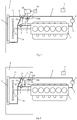
- FIG. 1 shows a cooling system to cool a combustion engine 1 in a schematically shown vehicle 2.
- the cooling fluid is circulated in the cooling system with the aid of a cooling fluid pump 3 that is arranged in an inlet line 4 to the combustion engine 1.
- a cooling fluid pump 3 that is arranged in an inlet line 4 to the combustion engine 1.
- the cooling system is used for the cooling of a further component, in addition to the combustion engine 1.
- the retarder 6 is in this case a hydraulic retarder that uses cooling fluid as its working medium.
- the vehicle 2 comprises also a further supplementary brake in the form of an exhaust gas brake 7, shown schematically.
- Supplementary brakes such as the retarder 6 and the exhaust gas brakes 7 are many times used in heavy vehicles 2 in order to reduce wear on the ordinary wheel brakes.
- the cooling fluid is led from the retarder 6, through an outlet line 8 of the retarder 6, to a thermostat 9.
- the thermostat 9 can be set into a closed condition in which it leads cooling fluid from the line 9 to a bypass line 10 that is connected by the inlet line 4 to the combustion engine 1.
- the thermostat 9 can be set into an open condition in which it leads cooling fluid from the line 8 to a cooler 12 through a line 11.
- the cooler 12 is mounted at the front part of the vehicle 2.
- a cooling fan 13 draws a cooling stream of air through the cooler 12 such that the cooling fluid that circulates through the cooler 12 undergoes effective cooling. After cooling fluid has been cooled in the cooler 12 it is led through a return line 14 back to the inlet line 4 and the cooling fluid pump 3.
- the thermostat 9 is connected to a sensor 15.
- the sensor 15 may comprise a sheath with a closed compartment that is occupied by a wax body.
- the wax body has the property that it increases in volume when it melts and passes into the fluid phase.
- the closed compartment of the sensor 15 may be defined by a flexible membrane that is fixed attached at a control rod.
- the control rod is connected at its opposite end to the thermostat 9.
- the thermostat is held in the closed condition with the aid of the membrane and the control rod.
- the wax inside the sensor 15 melts, it increases in volume such that the membrane and the control rod acquire a displacement that sets the thermostat 9 into its open condition.
- the sensor 15 is arranged in a pilot line 16.
- the pilot line 16 comprises a first inlet section 16a that has an opening for the reception of cooling fluid from the inlet line 4 in a location between the cooling fluid pump 3 and the combustion engine 1.
- the first inlet section 16a leads cooling fluid to a three-way valve 17.
- the pilot line 16 comprises a second inlet section 16b that has an opening for the reception of cooling fluid from the outlet line 8 of the retarder.
- the opening of the second inlet section 16b is located in the outlet line 8 of the retarder 6.
- the second inlet section 16b leads cooling fluid also to the three-way valve 17.
- the pilot line 16 leads cooling fluid from the three-way valve 17 to an outlet opening in the bypass line 10.
- the sensor 15 is adapted to sense the temperature of the cooling fluid in the pilot line 16.
- a control unit 18 is adapted to control the three-way valve 17 using information from a braking control 19 or another component in the vehicle, which control can provide information at least about whether the retarder 6 is activated or not. It is advantageous that the control unit receive information also about the braking power or similar parameter of the retarder 6, which information is related to the cooling power that the retarder 6 requires.
- Cooling fluid circulates around the cooling system during operation of the combustion engine 1.
- the control unit 18 receives information from the braking control 19 that indicates whether the retarder is activated or not. When the control unit 18 receives information that indicates that the retarder 6 is not activated, it places the three-way valve 17 into its first condition. Cooling fluid is thus led from the first inlet section 16a to the pilot line 16.
- the sensor 15 senses in this way the temperature of the cooling fluid in the inlet line 4 to the combustion engine 1. If the cooling fluid has a temperature that is lower than the regulating temperature of the thermostat 9, the thermostat 9 is set into its closed condition. The cooling fluid in the line 8 is led in this case to the bypass line 10 and thus to the combustion engine 1 without cooling. If the sensor 15 senses that the cooling fluid has a temperature that is higher than the regulating temperature of the thermostat 9, the thermostat 9 is set into its open condition. The cooling fluid in the line 8 is led in this case to the cooler 12 for cooling before it is led to the combustion engine 1.
- the thermostat 9 Following a cold start of the vehicle, the thermostat 9 initially leads the cooling fluid to the bypass line 10 and to the combustion engine 1 without cooling. When the cooling fluid has warmed up to the regulating temperature, the thermostat 9 opens such that cooling fluid is led to the cooler 12. The cooling fluid obtains in this case a suddenly lowered temperature in the cooler 12. Since the pilot line 16 receives cooling fluid, through the inlet section 16a, from the inlet line 4, the cooling system receives a rapid indication that the temperature of the cooling fluid has fallen. The thermostat 9 is closed and cooling fluid is again led without cooling to the combustion engine 1, during a period. With such a rapid feedback and control of the thermostat 9, a stable temperature of the cooling fluid can be obtained relatively rapidly and with relatively few resettings of the thermostat 9. The problem of temperature cycling can in this way be avoided.
- the control unit 18 When the control unit 18 receives information from the brake control 19 that indicates that the retarder 6 has been activated, it sets the three-way valve 17 into its second condition. Cooling fluid is thus led from the second inlet section 16b to the pilot line 16.
- the sensor 15 senses in this way the temperature of the cooling fluid in the outlet line 8 of the retarder.
- the thermostat 9 has a regulating temperature that has been dimensioned according to the temperature that cooling fluid has in the inlet line 4 to the combustion engine 1.
- the temperature of the cooling fluid in the outlet line 8 of the retarder is essentially always higher than it is in the inlet line 4 to the combustion engine 1.
- the cooling fluid will essentially always have a temperature that is higher than the regulating temperature of the thermostat 9.
- the sensor 15 senses that the cooling fluid has a higher temperature than the regulating temperature and the thermostat 9 is thus set into an open condition as soon as the retarder 6 has been activated. This results in the cooling fluid receiving optimal cooling as soon as the retarder 6 has been activated. Since a retarder 6 essentially always requires a high cooling power, it is an advantage that the thermostat 9 be set into the open condition as soon as possible and that it is retained in this condition during the complete period that the retarder 9 is activated. Alternatively, the control unit 18 can estimate the cooling power of the retarder 6 and reset the three-way valve 17 only when the retarder 6 has a cooling power that lies above a threshold value that is greater than zero.
- Figure 2 shows an alternative embodiment of the cooling system.
- the first inlet section 16a comprises a one-way valve 16c and a restriction 16f.
- the second inlet section 16b comprises a one-way valve 16d and a spring 16e that defines an opening pressure for the one-way valve 16d.
- the restriction 16f is dimensioned such that a fall in pressure is obtained in the first inlet line 16a of a magnitude that ensures that the cooling fluid in the first section of line 16a acquires a lower pressure than the cooling fluid in the second section of line 16b in connection with the pilot line 16.
- the pressure in the outlet line 8 of the retarder is not sufficiently high to open the one-way valve 16d, cooling fluid is led from the first section of line 16a to the pilot line 16.
- cooling fluid is led from the second section of line 16b to the pilot line 16 since the cooling fluid in the second section of line 16b has a higher pressure than the cooling fluid in the first section of line 16a in connection to the pilot line 16.
- the cooling fluid pump 3 is driven in conventional manner by the combustion engine 1 using a suitable transmission, not shown in the drawings.
- the cooling fluid pump 3 achieves in this way a rate of revolution that is related to the rate of revolution of the combustion engine 1.
- the increase in pressure that the cooling fluid undergoes when it is set under pressure by the cooling fluid pump 3 varies with the rate of revolution of the cooling fluid pump 3 and thus with the rate of revolution of the combustion engine 1.
- the pressure of the cooling fluid in the cooling system will thus be higher as the cooling system pump 3 and the combustion engine 1 demonstrate higher rates of revolution.
- the magnitude of the pressure decreases gradually with the distance from the pressurised side of the cooling fluid pump 3 to its suction side. Since the fall in pressure in the cooler 12 is relatively large, a relatively large portion of the pressure with which the cooling fluid has been set under pressure by the cooling fluid pump 3 can be demonstrated in the line 8.
- the vehicle 2 comprises a retarder 6 and an exhaust gas brake 7.
- both the retarder and the exhaust gas brake are, in general, activated.
- An exhaust gas brake 7 requires a high rate of revolution of the engine in order to create a high braking power.
- the brake system in the vehicle 2 thus provides an automatic gearing down if this is required when the exhaust gas brake 7 is activated, such that it gives an effective braking effect.
- the cooling fluid pump 3 is driven by the combustion engine 1, it acquires a correspondingly high rate of revolution when the supplementary brakes 6, 7 are activated. A high rate of revolution of the cooling fluid pump results in a high pressure in the cooling system.
- the spring 16e is adapted to open the one-way valve when the pressure in the line 8 exceeds a pre-determined value of pressure.
- this value of pressure can correspond to a rate of revolution of the diesel engine of an order of magnitude of 1600-1700 rpm.
- Cooling fluid circulates around the cooling system during operation of the combustion engine 1. In operating conditions in which the combustion engine 1 is driven with a low rate of revolution, a low pressure is obtained in the cooling system.
- the pressure in the line 8 is thus lower than the pressure that is required to open the one-way valve 16d against the effect of the said spring 16e.
- Cooling fluid from the first section of line 16a is in this way led through the one-way valve 16c and the restriction 16f, to the pilot line 16.
- the sensor 15 senses the temperature of the cooling fluid in the pilot line 16, which in this case corresponds to the temperature of the cooling fluid in the inlet line 4 to the combustion engine 1. If the cooling fluid has a temperature that is lower than the regulating temperature of the thermostat 9, the thermostat 9 is set into its closed condition.
- the cooling fluid in the line 8 is in this case led to the bypass line 10 and thus to the combustion engine 1 without undergoing cooling in the cooler 12. If the sensor 15 senses that the cooling fluid has a temperature that is higher than the regulating temperature of the thermostat 9, the thermostat 9 is set into its open condition. The cooling fluid in the line 8 is led in this case to the cooler 12 for cooling before it is led again to the combustion engine 1.
- the one-way valve 16d opens against the effect of the spring 16e. Cooling fluid is in this way led from the line 8 to the pilot line 16. Cooling fluid that is led into the pilot line 16 from the line 8 has a higher pressure such that the cooling fluid in the first section of line 16a. Cooling fluid from the first section of line 16a can in this way reach the pilot line 16.
- the sensor 15 senses the temperature of the cooling fluid in the pilot line 16, which in this case corresponds to the temperature of the cooling fluid in the outlet line 8 of the retarder.
- the regulating temperature of the thermostat 9 has been dimensioned according to the temperature that cooling fluid has in the inlet line 4 to the combustion engine 1.
- the temperature of the cooling fluid in the line 8 is essentially always a higher temperature than it is in the inlet line 4.
- the cooling fluid in the line 8 will essentially always have a higher temperature than the regulating temperature of the thermostat 9.
- the sensor 15 sets the thermostat 9 into an open condition as soon as the supplementary brakes 6, 7 are activated with a braking power above a threshold value that is defined by the pressure in the line 8.
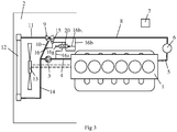
- Figure 3 shows an alternative embodiment of the cooling system.
- the first section of line 16a and the second section of line 16b are controlled by a displaceable valve body 20 that can be defined as a three-way valve.
- the valve body 20 is held in a first condition with the aid of a spring 16g.
- the first section of line 16a is connected to the pilot line 16 while at the same time the valve body 20 breaks the connection between the second section of line 16b and the pilot line 16.
- the second section of line 16b comprises a section of line 16b 1 that exerts a pressure on the valve body 20 in an opposing direction to that of the spring 16g.
- the spring 16g is dimensioned such that it holds the valve body 20 in the first condition with a pre-determined pressure.
- a pressure that is higher than the pressure that the spring 16g exerts the valve body 20 is displaced to a second position. In the second position, the valve body 20 connects the second section of line 16b to the pilot line 16, while at the same time the connection between the second section of line 16b and the pilot line 16 is broken.
- Cooling fluid circulates around the cooling system during operation of the combustion engine 1. In operating conditions in which the combustion engine 1 is driven with a low rate of revolution, a low pressure is obtained in the cooling system. The pressure in the line 8 is thus lower than the pressure that is required to open the one-way valve 16d. Cooling fluid from the first section of line 16a is in this way led to the pilot line 16.
- the sensor 15 senses the temperature of the cooling fluid in the pilot line 16, which in this case corresponds to the temperature of the cooling fluid in the inlet line 4 to the combustion engine 1. If the cooling fluid has a temperature that is lower than the regulating temperature of the thermostat 9, the thermostat 9 is set into its closed condition.
- the cooling fluid in the line 8 is led in this case to the bypass line 10 and thus to the combustion engine 1 without undergoing cooling in the cooler 12. If the sensor 15 senses that the cooling fluid has a temperature that is higher than the regulating temperature of the thermostat 9, the thermostat 9 is set into its open condition. The cooling fluid in the line 8 is led in this case to the cooler 12 for cooling before it is led again to the combustion engine 1.
- the one-way valve 16d opens against the effect of the spring 16e. Cooling fluid is in this way led from the line 8 to the pilot line 16.
- the sensor 15 senses the temperature of the cooling fluid in the pilot line 16, which in this case corresponds to the temperature of the cooling fluid in the outlet line 8 of the retarder.
- the regulating temperature of the thermostat 9 has been dimensioned according to the temperature that cooling fluid has in the inlet line 4 to the combustion engine 1.
- the temperature of the cooling fluid in the line 8 is essentially always a higher temperature than it is in the inlet line 4.
- the cooling fluid in the line 8 will essentially always have a higher temperature than the regulating temperature of the thermostat 9.
- the sensor 15 sets the thermostat 9 into an open condition as soon as the supplementary brakes 6, 7 are activated with a braking power above a threshold value that is defined by the pressure in the line 8.
- a rapid feedback and an effective cooling of the cooling fluid is obtained in operating conditions in which the combustion engine 1 is driven at a high rate of revolution.
- a high rate of revolution of the engine normally means that the engine is under a heavy load and that the cooling fluid should be given a thorough cooling.
- the invention is not in any way limited to the embodiment that has been described in the drawings: it can be freely varied within the scope of the patent claims.
- the component that can be activated intermittently is exemplified in the embodiments as a hydraulic retarder.
- the component that can be activated intermittently may be any freely chosen component that requires a high cooling power.
Landscapes
- Engineering & Computer Science (AREA)
- Mechanical Engineering (AREA)
- Physics & Mathematics (AREA)
- General Engineering & Computer Science (AREA)
- Fluid Mechanics (AREA)
- Transportation (AREA)
- Chemical & Material Sciences (AREA)
- Combustion & Propulsion (AREA)
- General Physics & Mathematics (AREA)
- Automation & Control Theory (AREA)
- Transmission Of Braking Force In Braking Systems (AREA)
- Cooling, Air Intake And Gas Exhaust, And Fuel Tank Arrangements In Propulsion Units (AREA)
- Air-Conditioning For Vehicles (AREA)
Claims (10)
- Système de refroidissement dans un véhicule pour le refroidissement d'un moteur à combustion (1) et d'un composant (6) qui peut être activé de façon intermittente, dans lequel le système de refroidissement comprend une pompe (3) pour le fluide de refroidissement qui est adaptée pour faire circuler le fluide de refroidissement dans le système de refroidissement, un radiateur (12) pour le refroidissement du fluide de refroidissement, une ligne pilote (16) qui comprend une première partie d'entrée (16a) où le fluide de refroidissement est reçu d'une ligne (4) dans le système de refroidissement qui conduit le fluide de refroidissement dans le moteur à combustion (1) et une deuxième partie d'entrée (16b) qui reçoit du fluide de refroidissement d'une ligne (8) dans le système de refroidissement qui reçoit du fluide de refroidissement du composant (6), un capteur (15) qui est adapté pour capter la température du fluide de refroidissement dans la ligne pilote (16) et un thermostat (9) qui est adapté pour conduire le fluide de refroidissement au moteur à combustion (1) sans refroidissement lorsque le capteur (15) constate que la température du fluide de refroidissement dans la ligne pilote (16) est inférieure à une température de réglage et pour conduire le fluide de refroidissement au radiateur (12) avant qu'il ne soit conduit au moteur à combustion (1) lorsque le capteur constate que la température du fluide de refroidissement dans la ligne pilote (16) est supérieure à la température de réglage, caractérisé en ce que le système de refroidissement comprend un agencement de valves (16c, 16d, 17, 20) qui conduit du fluide de refroidissement uniquement de la première partie d'entrée (16a) à la ligne pilote (16) en présence d'une première condition et qui conduit du fluide de refroidissement uniquement de la deuxième partie d'entrée (16b) à la ligne pilote (16) en présence d'une deuxième condition, et des moyens de commande (16b1, 16e, 16g, 18) qui sont adaptés pour mettre l'agencement de valves dans la première condition lorsque le composant est activé et demande une puissance de refroidissement qui est inférieure à une valeur seuil, et dans la deuxième condition lorsque le composant (6) est activé et demande une puissance de refroidissement qui est supérieure à la valeur seuil.
- Système de refroidissement selon la revendication 1, caractérisé en ce que l'agencement de valves comprend une valve à trois voies (17).
- Système de refroidissement selon la revendication 1 ou 2, caractérisé en ce que les moyens de commande comprennent une unité de commande (18) qui est adaptée pour recevoir des informations (19) concernant au moins un paramètre qui indique si le composant (6) demande une puissance de refroidissement inférieure ou supérieure à la valeur seuil et pour mettre l'agencement de valves (17), à l'aide de ces informations, dans la première condition ou dans la deuxième condition.
- Système de refroidissement selon l'une des revendications précédentes, caractérisé en ce que le composant est un ralentisseur hydraulique (6).
- Système de refroidissement selon la revendication 4, caractérisé en ce que le ralentisseur hydraulique (6) utilise le fluide de refroidissement comme fluide de travail.
- Système de refroidissement selon la revendication 4 ou 5, caractérisé en ce que le véhicule comprend aussi un frein à gaz d'échappement (7) et en ce que les moyens de commande (16b1, 16e, 16g) sont adaptés pour mettre l'agencement de valves (17) dans la première condition ou dans la deuxième condition en fonction de la pression du fluide de refroidissement dans le système de refroidissement.
- Système de refroidissement selon la revendication 6, caractérisé en ce que les moyens de commande (16b1, 16e, 16g) sont adaptés pour mettre l'agencement de valves dans la première condition ou dans la deuxième condition en fonction de la pression du fluide de refroidissement dans la ligne (8) qui reçoit du fluide de refroidissement du composant (6).
- Système de refroidissement selon la revendication 6 ou 7, caractérisé en ce que la première partie d'entrée (16a) comprend une première valve à une voie (16c) et un étranglement (16f) et en ce que la deuxième partie d'entrée (16b) comprend une deuxième valve à une voie (16d) qui est maintenue en un état fermé par un ressort (16e), le ressort (16e) ayant des dimensions telles que la deuxième valve à une voie (16d) ouvre de manière telle que du fluide de refroidissement est conduit de la deuxième partie d'entrée (16b) à la ligne pilote (16) lorsque la pression dans le système de refroidissement dépasse un niveau prédéterminé.
- Système de refroidissement selon l'une des revendications précédentes, caractérisé en ce que la pompe (3) pour le fluide de refroidissement est disposée dans la ligne (4) qui conduit du fluide de refroidissement au moteur à combustion (1) et en ce que la première partie d'entrée (16a) reçoit du fluide de refroidissement dans la ligne (4) à une position en aval de la pompe (3) pour le fluide de refroidissement.
- Système de refroidissement selon l'une des revendications précédentes, caractérisé en ce que la ligne pilote (16) comprend une sortie qui est située dans une ligne by-pass (10) qui conduit du fluide de refroidissement du thermostat (9) à la ligne d'entrée (4) du moteur à combustion.
Applications Claiming Priority (2)
| Application Number | Priority Date | Filing Date | Title |
|---|---|---|---|
| SE1251444A SE1251444A1 (sv) | 2012-12-18 | 2012-12-18 | Kylsystem i ett fordon |
| PCT/SE2013/051384 WO2014098711A1 (fr) | 2012-12-18 | 2013-11-25 | Système de refroidissement dans un véhicule |
Publications (3)
| Publication Number | Publication Date |
|---|---|
| EP2935822A1 EP2935822A1 (fr) | 2015-10-28 |
| EP2935822A4 EP2935822A4 (fr) | 2016-08-17 |
| EP2935822B1 true EP2935822B1 (fr) | 2018-01-10 |
Family
ID=50721188
Family Applications (1)
| Application Number | Title | Priority Date | Filing Date |
|---|---|---|---|
| EP13864357.2A Active EP2935822B1 (fr) | 2012-12-18 | 2013-11-25 | Système de refroidissement dans un véhicule |
Country Status (6)
| Country | Link |
|---|---|
| EP (1) | EP2935822B1 (fr) |
| KR (1) | KR20150097749A (fr) |
| BR (1) | BR112015013733A2 (fr) |
| RU (1) | RU2602019C1 (fr) |
| SE (1) | SE1251444A1 (fr) |
| WO (1) | WO2014098711A1 (fr) |
Families Citing this family (6)
| Publication number | Priority date | Publication date | Assignee | Title |
|---|---|---|---|---|
| CN104359651B (zh) * | 2014-12-03 | 2017-04-05 | 中国北方车辆研究所 | 一种液力减速器变充液率动态特性可视化试验方法 |
| CN104458231B (zh) * | 2014-12-03 | 2017-04-05 | 中国北方车辆研究所 | 一种液力减速器固定充液率动态特性可视化试验方法 |
| SE540767C2 (en) * | 2017-03-06 | 2018-11-06 | Scania Cv Ab | A thermostat device for a cooling system |
| WO2018197586A1 (fr) * | 2017-04-26 | 2018-11-01 | Dana Belgium N.V. | Système ralentisseur hydrodynamique et procédé de commande d'un système ralentisseur hydrodynamique |
| CN112943438B (zh) * | 2019-11-26 | 2024-10-29 | 陕西重型汽车有限公司 | 一种商用车用先导控制的液力缓速器冷却系统 |
| KR102791585B1 (ko) * | 2020-09-11 | 2025-04-04 | 현대자동차주식회사 | 수소 연료전지 트럭의 보조제동장치 냉각 시스템 및 방법 |
Family Cites Families (9)
| Publication number | Priority date | Publication date | Assignee | Title |
|---|---|---|---|---|
| US4700888A (en) * | 1986-06-18 | 1987-10-20 | Cummins Engine Company, Inc. | Auxiliary heater controller |
| DE3700037C2 (de) * | 1987-01-02 | 1995-12-21 | Voith Turbo Kg | Kühlanlage für die gemeinsame Kühlflüssigkeit der Antriebsmaschine sowie eines Retarders eines Fahrzeuges |
| DE19848544C1 (de) * | 1998-10-22 | 2000-06-21 | Voith Turbo Kg | Verfahren und Vorrichtung zur Erhöhung der Bremsmomentenausnutzung eines hydrodynamischen Retarders in einem Kraftfahrzeug |
| JP4012421B2 (ja) * | 2002-03-20 | 2007-11-21 | トヨタ自動車株式会社 | エンジンの冷却装置 |
| DE102005061476A1 (de) * | 2005-12-22 | 2007-06-28 | Audi Ag | Ventilvorrichtung |
| JP4277046B2 (ja) * | 2007-02-28 | 2009-06-10 | トヨタ自動車株式会社 | 内燃機関の冷却装置 |
| SE532354C2 (sv) * | 2007-09-11 | 2009-12-22 | Scania Cv Abp | Kylsystem och termostatanordning för motorfordon |
| FR2933738B1 (fr) * | 2008-07-11 | 2010-08-13 | Renault Sas | Procede de controle de debit de liquide de refroidissement |
| SE535781C2 (sv) * | 2011-04-29 | 2012-12-18 | Scania Cv Ab | Kylsystem för kylning av en förbränningsmotor |
-
2012
- 2012-12-18 SE SE1251444A patent/SE1251444A1/sv unknown
-
2013
- 2013-11-25 EP EP13864357.2A patent/EP2935822B1/fr active Active
- 2013-11-25 RU RU2015129114/06A patent/RU2602019C1/ru not_active IP Right Cessation
- 2013-11-25 KR KR1020157019535A patent/KR20150097749A/ko not_active Abandoned
- 2013-11-25 BR BR112015013733A patent/BR112015013733A2/pt not_active Application Discontinuation
- 2013-11-25 WO PCT/SE2013/051384 patent/WO2014098711A1/fr not_active Ceased
Non-Patent Citations (1)
| Title |
|---|
| None * |
Also Published As
| Publication number | Publication date |
|---|---|
| BR112015013733A2 (pt) | 2017-07-11 |
| EP2935822A4 (fr) | 2016-08-17 |
| WO2014098711A1 (fr) | 2014-06-26 |
| SE536681C2 (sv) | 2014-05-20 |
| RU2602019C1 (ru) | 2016-11-10 |
| EP2935822A1 (fr) | 2015-10-28 |
| SE1251444A1 (sv) | 2014-05-20 |
| KR20150097749A (ko) | 2015-08-26 |
Similar Documents
| Publication | Publication Date | Title |
|---|---|---|
| EP2935822B1 (fr) | Système de refroidissement dans un véhicule | |
| EP2118456B1 (fr) | Agencement de chauffage d'huile dans une boite de vitesses | |
| EP2198137B1 (fr) | Agencement permettant de refroidir l'huile dans une boîte de vitesse d'un véhicule | |
| JP4330453B2 (ja) | 液圧システム及びオートマチックトランスミッション | |
| EP2310692B1 (fr) | Régulation de débit | |
| EP2037097B1 (fr) | Système de refroidissement et dispositif de thermostat pour véhicule à moteur | |
| EP0965737A2 (fr) | Système de commande pour un refroidissement total d'un moteur à combustion interne | |
| EP2935821B1 (fr) | Système de refroidissement destiné à un véhicule hybride propulsé mécaniquement et hydrauliquement | |
| CN105658927B (zh) | 车辆中的冷却系统 | |
| US10107382B2 (en) | Vehicular drive system | |
| US6817455B1 (en) | Retarder system | |
| EP2795078A1 (fr) | Dispositif et procédé pour refroidissement d'agent de refroidissement dans un système de refroidissement dans un véhicule | |
| EP2932061B1 (fr) | Système de refroidissement | |
| JP2014513763A (ja) | 燃焼機関を冷却するための冷却システム | |
| GB2464712A (en) | Air conditioning control system | |
| Kern et al. | Concepts for a controlled optimized vehicle engine cooling system | |
| CN110925400B (zh) | 机械式自动变速箱以及汽车 | |
| EP2785545B1 (fr) | Système de régulation du flux de liquide dans un véhicule | |
| CN110131447A (zh) | 连接器 | |
| SE1850618A1 (en) | A cooling system for an engine and a water retarder | |
| SE541849C2 (en) | A cooling system for cooling of a combustion engine and further object | |
| WO2014098710A1 (fr) | Agencement de thermostat et système de refroidissement |
Legal Events
| Date | Code | Title | Description |
|---|---|---|---|
| PUAI | Public reference made under article 153(3) epc to a published international application that has entered the european phase |
Free format text: ORIGINAL CODE: 0009012 |
|
| 17P | Request for examination filed |
Effective date: 20150720 |
|
| AK | Designated contracting states |
Kind code of ref document: A1 Designated state(s): AL AT BE BG CH CY CZ DE DK EE ES FI FR GB GR HR HU IE IS IT LI LT LU LV MC MK MT NL NO PL PT RO RS SE SI SK SM TR |
|
| AX | Request for extension of the european patent |
Extension state: BA ME |
|
| DAX | Request for extension of the european patent (deleted) | ||
| A4 | Supplementary search report drawn up and despatched |
Effective date: 20160714 |
|
| RIC1 | Information provided on ipc code assigned before grant |
Ipc: F16D 57/00 20060101ALI20160708BHEP Ipc: F16D 65/78 20060101ALI20160708BHEP Ipc: G05D 23/30 20060101ALI20160708BHEP Ipc: F01P 3/12 20060101ALI20160708BHEP Ipc: G05D 23/19 20060101ALI20160708BHEP Ipc: G05D 23/02 20060101ALI20160708BHEP Ipc: B60T 1/087 20060101ALI20160708BHEP Ipc: F01P 7/16 20060101AFI20160708BHEP Ipc: B60T 10/02 20060101ALI20160708BHEP |
|
| GRAP | Despatch of communication of intention to grant a patent |
Free format text: ORIGINAL CODE: EPIDOSNIGR1 |
|
| RIC1 | Information provided on ipc code assigned before grant |
Ipc: F16D 57/00 20060101ALI20170719BHEP Ipc: B60T 5/00 20060101ALI20170719BHEP Ipc: F01P 3/12 20060101ALI20170719BHEP Ipc: G05D 23/19 20060101ALI20170719BHEP Ipc: F01P 3/20 20060101ALI20170719BHEP Ipc: B60T 1/087 20060101ALI20170719BHEP Ipc: G05D 23/02 20060101ALI20170719BHEP Ipc: G05D 23/30 20060101ALI20170719BHEP Ipc: F16D 65/78 20060101ALI20170719BHEP Ipc: F01P 7/16 20060101AFI20170719BHEP Ipc: B60T 10/02 20060101ALI20170719BHEP |
|
| INTG | Intention to grant announced |
Effective date: 20170802 |
|
| RIN1 | Information on inventor provided before grant (corrected) |
Inventor name: HALL, OLA Inventor name: KARDOS, ZOLTAN |
|
| GRAS | Grant fee paid |
Free format text: ORIGINAL CODE: EPIDOSNIGR3 |
|
| GRAA | (expected) grant |
Free format text: ORIGINAL CODE: 0009210 |
|
| AK | Designated contracting states |
Kind code of ref document: B1 Designated state(s): AL AT BE BG CH CY CZ DE DK EE ES FI FR GB GR HR HU IE IS IT LI LT LU LV MC MK MT NL NO PL PT RO RS SE SI SK SM TR |
|
| REG | Reference to a national code |
Ref country code: CH Ref legal event code: EP Ref country code: AT Ref legal event code: REF Ref document number: 962661 Country of ref document: AT Kind code of ref document: T Effective date: 20180115 |
|
| REG | Reference to a national code |
Ref country code: IE Ref legal event code: FG4D |
|
| REG | Reference to a national code |
Ref country code: DE Ref legal event code: R096 Ref document number: 602013032224 Country of ref document: DE |
|
| REG | Reference to a national code |
Ref country code: NL Ref legal event code: MP Effective date: 20180110 |
|
| REG | Reference to a national code |
Ref country code: AT Ref legal event code: MK05 Ref document number: 962661 Country of ref document: AT Kind code of ref document: T Effective date: 20180110 |
|
| PG25 | Lapsed in a contracting state [announced via postgrant information from national office to epo] |
Ref country code: NL Free format text: LAPSE BECAUSE OF FAILURE TO SUBMIT A TRANSLATION OF THE DESCRIPTION OR TO PAY THE FEE WITHIN THE PRESCRIBED TIME-LIMIT Effective date: 20180110 |
|
| PG25 | Lapsed in a contracting state [announced via postgrant information from national office to epo] |
Ref country code: FI Free format text: LAPSE BECAUSE OF FAILURE TO SUBMIT A TRANSLATION OF THE DESCRIPTION OR TO PAY THE FEE WITHIN THE PRESCRIBED TIME-LIMIT Effective date: 20180110 Ref country code: LT Free format text: LAPSE BECAUSE OF FAILURE TO SUBMIT A TRANSLATION OF THE DESCRIPTION OR TO PAY THE FEE WITHIN THE PRESCRIBED TIME-LIMIT Effective date: 20180110 Ref country code: CY Free format text: LAPSE BECAUSE OF FAILURE TO SUBMIT A TRANSLATION OF THE DESCRIPTION OR TO PAY THE FEE WITHIN THE PRESCRIBED TIME-LIMIT Effective date: 20180110 Ref country code: NO Free format text: LAPSE BECAUSE OF FAILURE TO SUBMIT A TRANSLATION OF THE DESCRIPTION OR TO PAY THE FEE WITHIN THE PRESCRIBED TIME-LIMIT Effective date: 20180410 Ref country code: ES Free format text: LAPSE BECAUSE OF FAILURE TO SUBMIT A TRANSLATION OF THE DESCRIPTION OR TO PAY THE FEE WITHIN THE PRESCRIBED TIME-LIMIT Effective date: 20180110 Ref country code: HR Free format text: LAPSE BECAUSE OF FAILURE TO SUBMIT A TRANSLATION OF THE DESCRIPTION OR TO PAY THE FEE WITHIN THE PRESCRIBED TIME-LIMIT Effective date: 20180110 |
|
| PG25 | Lapsed in a contracting state [announced via postgrant information from national office to epo] |
Ref country code: IS Free format text: LAPSE BECAUSE OF FAILURE TO SUBMIT A TRANSLATION OF THE DESCRIPTION OR TO PAY THE FEE WITHIN THE PRESCRIBED TIME-LIMIT Effective date: 20180510 Ref country code: BG Free format text: LAPSE BECAUSE OF FAILURE TO SUBMIT A TRANSLATION OF THE DESCRIPTION OR TO PAY THE FEE WITHIN THE PRESCRIBED TIME-LIMIT Effective date: 20180410 Ref country code: AT Free format text: LAPSE BECAUSE OF FAILURE TO SUBMIT A TRANSLATION OF THE DESCRIPTION OR TO PAY THE FEE WITHIN THE PRESCRIBED TIME-LIMIT Effective date: 20180110 Ref country code: RS Free format text: LAPSE BECAUSE OF FAILURE TO SUBMIT A TRANSLATION OF THE DESCRIPTION OR TO PAY THE FEE WITHIN THE PRESCRIBED TIME-LIMIT Effective date: 20180110 Ref country code: SE Free format text: LAPSE BECAUSE OF FAILURE TO SUBMIT A TRANSLATION OF THE DESCRIPTION OR TO PAY THE FEE WITHIN THE PRESCRIBED TIME-LIMIT Effective date: 20180110 Ref country code: LV Free format text: LAPSE BECAUSE OF FAILURE TO SUBMIT A TRANSLATION OF THE DESCRIPTION OR TO PAY THE FEE WITHIN THE PRESCRIBED TIME-LIMIT Effective date: 20180110 Ref country code: GR Free format text: LAPSE BECAUSE OF FAILURE TO SUBMIT A TRANSLATION OF THE DESCRIPTION OR TO PAY THE FEE WITHIN THE PRESCRIBED TIME-LIMIT Effective date: 20180411 Ref country code: PL Free format text: LAPSE BECAUSE OF FAILURE TO SUBMIT A TRANSLATION OF THE DESCRIPTION OR TO PAY THE FEE WITHIN THE PRESCRIBED TIME-LIMIT Effective date: 20180110 |
|
| REG | Reference to a national code |
Ref country code: FR Ref legal event code: PLFP Year of fee payment: 6 Ref country code: DE Ref legal event code: R097 Ref document number: 602013032224 Country of ref document: DE |
|
| PG25 | Lapsed in a contracting state [announced via postgrant information from national office to epo] |
Ref country code: IT Free format text: LAPSE BECAUSE OF FAILURE TO SUBMIT A TRANSLATION OF THE DESCRIPTION OR TO PAY THE FEE WITHIN THE PRESCRIBED TIME-LIMIT Effective date: 20180110 Ref country code: EE Free format text: LAPSE BECAUSE OF FAILURE TO SUBMIT A TRANSLATION OF THE DESCRIPTION OR TO PAY THE FEE WITHIN THE PRESCRIBED TIME-LIMIT Effective date: 20180110 Ref country code: RO Free format text: LAPSE BECAUSE OF FAILURE TO SUBMIT A TRANSLATION OF THE DESCRIPTION OR TO PAY THE FEE WITHIN THE PRESCRIBED TIME-LIMIT Effective date: 20180110 Ref country code: AL Free format text: LAPSE BECAUSE OF FAILURE TO SUBMIT A TRANSLATION OF THE DESCRIPTION OR TO PAY THE FEE WITHIN THE PRESCRIBED TIME-LIMIT Effective date: 20180110 |
|
| PLBE | No opposition filed within time limit |
Free format text: ORIGINAL CODE: 0009261 |
|
| STAA | Information on the status of an ep patent application or granted ep patent |
Free format text: STATUS: NO OPPOSITION FILED WITHIN TIME LIMIT |
|
| PG25 | Lapsed in a contracting state [announced via postgrant information from national office to epo] |
Ref country code: DK Free format text: LAPSE BECAUSE OF FAILURE TO SUBMIT A TRANSLATION OF THE DESCRIPTION OR TO PAY THE FEE WITHIN THE PRESCRIBED TIME-LIMIT Effective date: 20180110 Ref country code: SK Free format text: LAPSE BECAUSE OF FAILURE TO SUBMIT A TRANSLATION OF THE DESCRIPTION OR TO PAY THE FEE WITHIN THE PRESCRIBED TIME-LIMIT Effective date: 20180110 Ref country code: SM Free format text: LAPSE BECAUSE OF FAILURE TO SUBMIT A TRANSLATION OF THE DESCRIPTION OR TO PAY THE FEE WITHIN THE PRESCRIBED TIME-LIMIT Effective date: 20180110 Ref country code: CZ Free format text: LAPSE BECAUSE OF FAILURE TO SUBMIT A TRANSLATION OF THE DESCRIPTION OR TO PAY THE FEE WITHIN THE PRESCRIBED TIME-LIMIT Effective date: 20180110 |
|
| 26N | No opposition filed |
Effective date: 20181011 |
|
| PG25 | Lapsed in a contracting state [announced via postgrant information from national office to epo] |
Ref country code: SI Free format text: LAPSE BECAUSE OF FAILURE TO SUBMIT A TRANSLATION OF THE DESCRIPTION OR TO PAY THE FEE WITHIN THE PRESCRIBED TIME-LIMIT Effective date: 20180110 |
|
| REG | Reference to a national code |
Ref country code: CH Ref legal event code: PL |
|
| PG25 | Lapsed in a contracting state [announced via postgrant information from national office to epo] |
Ref country code: MC Free format text: LAPSE BECAUSE OF FAILURE TO SUBMIT A TRANSLATION OF THE DESCRIPTION OR TO PAY THE FEE WITHIN THE PRESCRIBED TIME-LIMIT Effective date: 20180110 Ref country code: LU Free format text: LAPSE BECAUSE OF NON-PAYMENT OF DUE FEES Effective date: 20181125 |
|
| REG | Reference to a national code |
Ref country code: BE Ref legal event code: MM Effective date: 20181130 |
|
| REG | Reference to a national code |
Ref country code: IE Ref legal event code: MM4A |
|
| PG25 | Lapsed in a contracting state [announced via postgrant information from national office to epo] |
Ref country code: LI Free format text: LAPSE BECAUSE OF NON-PAYMENT OF DUE FEES Effective date: 20181130 Ref country code: CH Free format text: LAPSE BECAUSE OF NON-PAYMENT OF DUE FEES Effective date: 20181130 |
|
| PG25 | Lapsed in a contracting state [announced via postgrant information from national office to epo] |
Ref country code: IE Free format text: LAPSE BECAUSE OF NON-PAYMENT OF DUE FEES Effective date: 20181125 |
|
| PG25 | Lapsed in a contracting state [announced via postgrant information from national office to epo] |
Ref country code: BE Free format text: LAPSE BECAUSE OF NON-PAYMENT OF DUE FEES Effective date: 20181130 |
|
| PG25 | Lapsed in a contracting state [announced via postgrant information from national office to epo] |
Ref country code: MT Free format text: LAPSE BECAUSE OF NON-PAYMENT OF DUE FEES Effective date: 20181125 |
|
| PGFP | Annual fee paid to national office [announced via postgrant information from national office to epo] |
Ref country code: FR Payment date: 20191014 Year of fee payment: 7 |
|
| PG25 | Lapsed in a contracting state [announced via postgrant information from national office to epo] |
Ref country code: TR Free format text: LAPSE BECAUSE OF FAILURE TO SUBMIT A TRANSLATION OF THE DESCRIPTION OR TO PAY THE FEE WITHIN THE PRESCRIBED TIME-LIMIT Effective date: 20180110 |
|
| PGFP | Annual fee paid to national office [announced via postgrant information from national office to epo] |
Ref country code: GB Payment date: 20191122 Year of fee payment: 7 |
|
| PG25 | Lapsed in a contracting state [announced via postgrant information from national office to epo] |
Ref country code: PT Free format text: LAPSE BECAUSE OF FAILURE TO SUBMIT A TRANSLATION OF THE DESCRIPTION OR TO PAY THE FEE WITHIN THE PRESCRIBED TIME-LIMIT Effective date: 20180110 |
|
| PG25 | Lapsed in a contracting state [announced via postgrant information from national office to epo] |
Ref country code: MK Free format text: LAPSE BECAUSE OF NON-PAYMENT OF DUE FEES Effective date: 20180110 Ref country code: HU Free format text: LAPSE BECAUSE OF FAILURE TO SUBMIT A TRANSLATION OF THE DESCRIPTION OR TO PAY THE FEE WITHIN THE PRESCRIBED TIME-LIMIT; INVALID AB INITIO Effective date: 20131125 |
|
| GBPC | Gb: european patent ceased through non-payment of renewal fee |
Effective date: 20201125 |
|
| PG25 | Lapsed in a contracting state [announced via postgrant information from national office to epo] |
Ref country code: FR Free format text: LAPSE BECAUSE OF NON-PAYMENT OF DUE FEES Effective date: 20201130 |
|
| PG25 | Lapsed in a contracting state [announced via postgrant information from national office to epo] |
Ref country code: GB Free format text: LAPSE BECAUSE OF NON-PAYMENT OF DUE FEES Effective date: 20201125 |
|
| P01 | Opt-out of the competence of the unified patent court (upc) registered |
Effective date: 20230518 |
|
| PGFP | Annual fee paid to national office [announced via postgrant information from national office to epo] |
Ref country code: DE Payment date: 20250930 Year of fee payment: 13 |