EP2037097B1 - Système de refroidissement et dispositif de thermostat pour véhicule à moteur - Google Patents
Système de refroidissement et dispositif de thermostat pour véhicule à moteur Download PDFInfo
- Publication number
- EP2037097B1 EP2037097B1 EP08163515.3A EP08163515A EP2037097B1 EP 2037097 B1 EP2037097 B1 EP 2037097B1 EP 08163515 A EP08163515 A EP 08163515A EP 2037097 B1 EP2037097 B1 EP 2037097B1
- Authority
- EP
- European Patent Office
- Prior art keywords
- cooling medium
- cooling
- radiator
- thermostat
- wax element
- Prior art date
- Legal status (The legal status is an assumption and is not a legal conclusion. Google has not performed a legal analysis and makes no representation as to the accuracy of the status listed.)
- Active
Links
Images


Classifications
-
- F—MECHANICAL ENGINEERING; LIGHTING; HEATING; WEAPONS; BLASTING
- F01—MACHINES OR ENGINES IN GENERAL; ENGINE PLANTS IN GENERAL; STEAM ENGINES
- F01P—COOLING OF MACHINES OR ENGINES IN GENERAL; COOLING OF INTERNAL-COMBUSTION ENGINES
- F01P7/00—Controlling of coolant flow
- F01P7/14—Controlling of coolant flow the coolant being liquid
- F01P7/16—Controlling of coolant flow the coolant being liquid by thermostatic control
- F01P7/165—Controlling of coolant flow the coolant being liquid by thermostatic control characterised by systems with two or more loops
-
- F—MECHANICAL ENGINEERING; LIGHTING; HEATING; WEAPONS; BLASTING
- F01—MACHINES OR ENGINES IN GENERAL; ENGINE PLANTS IN GENERAL; STEAM ENGINES
- F01P—COOLING OF MACHINES OR ENGINES IN GENERAL; COOLING OF INTERNAL-COMBUSTION ENGINES
- F01P11/00—Component parts, details, or accessories not provided for in, or of interest apart from, groups F01P1/00 - F01P9/00
- F01P11/04—Arrangements of liquid pipes or hoses
-
- F—MECHANICAL ENGINEERING; LIGHTING; HEATING; WEAPONS; BLASTING
- F01—MACHINES OR ENGINES IN GENERAL; ENGINE PLANTS IN GENERAL; STEAM ENGINES
- F01P—COOLING OF MACHINES OR ENGINES IN GENERAL; COOLING OF INTERNAL-COMBUSTION ENGINES
- F01P2070/00—Details
- F01P2070/04—Details using electrical heating elements
Definitions
- the invention relates to a cooling system for a motor vehicle according to the preamble of claim 1.
- the invention also relates to a thermostat device according to the preamble of claim 6.
- the invention further relates to a motor vehicle.
- a cooling system for a liquid-cooled combustion engine of a motor vehicle comprises a radiator for cooling a cooling medium, a bypass line in which the cooling medium can bypass the radiator when the temperature of the cooling medium is low, a cooling medium pump for circulating the cooling medium through the radiator and/or the bypass line and the engine's cooling ducts, and a thermostat for directing the flow of the cooling medium to the radiator and/or the bypass line, depending on the temperature of the cooling medium.
- the control of the thermostat is by a thermal element in the form of a sensing device containing wax.
- the wax in the sensing device reacts to the temperature of the cooling medium in such a way that it melts at a certain temperature, whereby it acts upon a valve which opens so that the cooling medium can flow to the radiator.
- the wax cools and solidifies, whereupon the valve closes so that the cooling medium flows through the bypass line.
- This phase change of the wax takes a relatively long time, of the order of minutes, which time depends on the composition of the wax element.
- Advantages of using thermostats containing a thermal element/sensing device in the form of a wax element are that the latter results in high operational reliability and is very inexpensive.
- the thermostat On most heavy vehicles such as trucks, the thermostat is situated downstream of the engine.
- the problem with such a location is that there is no temperature regulation of the cooled cooling medium from the radiator which flows into the engine, since the sensing device is situated upstream of the radiator. Only when the cooled cooling medium has flowed through the engine and been warmed and comes back to the thermostat does any regulation take place. There is thus a considerable delay before the thermostat receives temperature feedback after a change of the valve position.
- the result In practice the result is a temperature rise process which oscillates, a transient pattern, which in some cases when high loads occur is not damped, as the thermostat "hunts" because of not being able to keep up with the rest of the cooling system.
- the circulation time of the cooling medium in the cooling system may be 20-30 seconds, depending on the flow.
- thermostat situated upstream of the engine where cold flow from the radiator and relatively warmer flow from the bypass line mix. This mixture will thus be at the sensitive temperature of the wax element at which the thermostat closes immediately if it becomes too cold, thereby reducing said oscillations and resulting in a transient pattern which is much more stable and is damped more quickly.
- thermostat upstream of the engine may entail substantial reconfiguration of, for example, a truck.
- pipelines of the cooling system have to be relaid and existing items relocated.
- the engine has to be reconfigured. It can take a number of years to develop a new engine block. Such relocation of the thermostat also affects many other components.
- EP1111215A1 discloses a thermostat device for a cooling system of a motor vehicle, comprising a valve device adapted to receiving cooling medium flowing downstream of the engine and a thermal element which is connected to the valve device and is adapted to detecting the temperature of the cooling medium of the cooling system.
- a valve device adapted to receiving cooling medium flowing downstream of the engine
- a thermal element which is connected to the valve device and is adapted to detecting the temperature of the cooling medium of the cooling system.
- the thermal element is arranged in the main incoming line from the radiator to the engine. Hereby the oscillations of the temperature in the engine may be minimized.
- An object of the present invention is to provide a cooling system for a cooling-medium-cooled combustion engine of a motor vehicle which results in better control of the flow of the cooling medium in the system without substantial reconfiguration of existing cooling systems in which the thermostat is situated downstream of the combustion engine.
- a further object of the present invention is to provide a thermostat device which is easy to install in existing cooling system configurations in which thermostats are situated downstream of the combustion engine, which thermostat device, when installed in such a cooling system, enables better control of the flow of the cooling medium.
- Temperature cycling is thus greatly reduced/damped, particularly during cold temperature-rise processes, the result being a more stable temperature in the engine.
- This makes it possible to regulate the cold cooling medium from the radiator so that the radiator is likewise not subject to temperature cycling. More stable engine operation is thus made possible.
- Such an arrangement of the thermal element makes for easy installation in existing cooling systems in which the thermostat device is situated downstream of the engine. No great reconfiguration is involved, since a thermostat device thus configured can replace a thermostat device situated downstream of the engine.
- the thermal element is so situated that it detects a partial flow of the mixed cooling medium from the radiator and the bypass line.
- situating the thermal element in this way reduces oscillations of the cooling medium temperature and results in an oscillation of said temperature which is more stable and more quickly damped.
- the thermal element comprises a sensing device in the form of a wax element. Advantages of using a wax element are that it results in high operational reliability and is very inexpensive.
- the wax element contains added substances such as, for example, aluminium powder, copper powder, carbon powder or the like for acting upon the thermal characteristics of the wax element so that the time the wax element takes to control the flow of the cooling medium from/to a situation in which substantially no cooling medium is caused to flow through the radiator to/from a situation in which substantially all of the cooling medium is caused to flow through the radiator is reduced.
- the wax element opens and closes quickly, resulting in quicker regulation of the cooling medium temperature.
- an electrical device is connected to the wax element to regulate the temperature of the wax element and hence the temperature at which the wax element is activated to control the cooling medium.
- the electrical device is coupled to the load by means of the engine, a supplementary brake and/or the like in such a way that the greater the load the more heat is imparted to the wax element.
- This is an easy way to control the opening temperature of the wax element so that a high opening temperature of the wax element occurs at low engine load and/or low retarder load and a low opening temperature at high engine load and/or retarder load.
- a partial flow of the mixed cooling medium from the radiator and the bypass line is led in a pilot line via the thermal element to the bypass line.
- the objects are also achieved with a thermostat device for a cooling system of a motor vehicle according to claim 6.
- the cold cooling medium from the radiator is thus regulated so that the radiator is likewise not subject to temperature cycling. More stable engine operation is thus made possible.
- Such an arrangement of the thermal element makes for easy installation in existing cooling systems in which the thermostat device is situated downstream of the engine. No great reconfiguration is involved, since a thermostat device thus configured can replace a thermostat device situated downstream of the engine.
- situating the thermal element in this way reduces oscillations of the cooling medium temperature and results in an oscillation of said temperature which is more stable and more quickly damped.
- the thermal element comprises a sensing device in the form of a wax element which results in high operational reliability and is very inexpensive.
- the wax element contains added substances such as, for example, aluminium powder, copper powder, carbon powder or the like, which increases the opening/closing speed of the wax element, i.e. the latter melts and solidifies more quickly, resulting in quicker regulation of the cooling medium temperature.
- an electrical device is connected to the wax element to regulate the temperature of the wax element and hence the temperature at which the wax element is activated to control the cooling medium.
- the electrical device is coupled to the load by means of the engine, a supplementary brake and/or the like in such a way that the greater the load the more heat is imparted to the wax element.
- This is an easy way to control the opening temperature of the wax element so that a high opening temperature of the wax element occurs at low engine load and/or low retarder load and a low opening temperature at high engine load and/or retarder load.
- a partial flow of the mixed cooling medium from the radiator and the bypass line is led in a pilot line via the thermal element to the bypass line.
- Fig. 1 depicts schematically a cooling system 1 for a combustion engine 100, e.g. a diesel engine, of a motor vehicle such as a truck or bus, according to an embodiment of the present invention.
- the cooling system 1 comprises a cooling circuit 2 situated in the vehicle's engine 100 and comprising cooling ducts 2a in which a cooling medium is caused to flow in order to cool the engine.
- the cooling medium takes the form of a liquid, preferably in the form of a mixture of water and freezing point lowering additives such as glycol.
- the cooling system 1 further comprises a radiator 20 for cooling the cooling medium, a cooling medium pump 30 for circulating the cooling medium in the cooling circuit, and a thermostat device 40 for controlling, according to temperature, the cooling medium in the cooling system.
- An outlet 102 from the engine's cooling ducts is connected to a first inlet 41 of the thermostat device via a first line 3.
- a first outlet 42 from the thermostat device is connected to an inlet 21 of the radiator via a second line 4.
- An outlet 22 from the radiator is connected to an inlet 31 of the cooling medium pump via a third line 5 and a fourth line 6.
- An outlet 32 from the cooling medium pump is directly connected to an inlet 101 to the engine's cooling ducts via a fifth line 7.
- a second outlet 44 from the thermostat device is connected to the inlet 31 to the cooling medium pump via a bypass line 8 which is connected at a connection 9 between the third and fourth lines.
- the bypass line 8 makes it possible for cooling medium to be led past the radiator 20.
- the pump 30 is here arranged between the fourth and fifth lines but may also be situated elsewhere in the cooling system.
- the cooling medium which flows through the radiator is cooled by air which blows against the radiator when the vehicle is in motion.
- the cooling system usually also comprises a fan (not depicted) which is adapted to providing, when required, extra cooling of the cooling medium.
- the fan is connected to the engine in such a way that its degree of connection depends on the engine load.
- a sixth line 11a which constitutes a first section of a pilot line 11 is connected at a connection 10 of the fifth line 7 and is connected to a second inlet 43 of the thermostat device.
- a seventh line 11b which constitutes a second section of the pilot line 11 runs from the second inlet 43 of the thermostat device.
- the seventh line 11b is connected to the bypass line 8.
- Heavy motor vehicles such as trucks are often equipped with supplementary brakes, e.g. a hydrodynamic retarder, for braking the vehicle, e.g. when travelling on downhill runs.
- the hydrodynamic retarder contains oil which flows at high velocity between a stator and a rotor, thereby converting the kinetic energy of the oil to thermal energy during braking.
- the cooling system of the motor vehicle is normally used for cooling the oil during the braking process, to which end the cooling system is provided with an extra heat exchanger whereby the cooling medium in the cooling system cools the warm oil from the retarder. The result is a very rapid temperature rise of the cooling medium.
- the cooling system according to the present invention is adapted to providing cooling during braking by a retarder 80 depicted in broken lines in Fig. 1 , or by an equivalent supplementary brake, whereby the thermostat device according to the present invention would provide quicker and more effective temperature regulation.
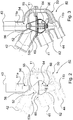
- Fig. 2 depicts schematically a thermostat device 40 according to a first embodiment of the present invention.
- the thermostat device 40 comprises a thermostat housing 50 and a valve device 52 accommodated therein and at least one thermal element 54 adapted to detecting the temperature of the cooling medium in order on the basis thereof to direct the cooling medium through the radiator 20 and/or to the bypass line 8 past the radiator 20.
- the thermal element comprises a sensing device 54 in the form of a wax element 54 configured in such a way and having such characteristics that it acts upon the valve device 52 when it is exposed to temperature changes.
- the wax element 54 is so situated that it detects part of the mixed cooling medium from the radiator 20 and the bypass line 8. According to an embodiment, the wax element 54 is situated close to the second inlet 43 of the thermostat device in such a way that it comes into contact with a portion of the mixed cooling medium from the radiator 20 and the bypass line 8.
- a portion of the mixed cooling medium from the radiator 20 and the bypass line is thus adapted to flowing through the pilot line 11, i.e. through the sixth and seventh lines, via the wax element 54 and being returned to the bypass line 8.
- the wax element is therefore not situated where the main flow of the cooling medium takes place but in a pilot flow through the pilot line 11.
- the fact that the wax element 54 detects a mixture of the relatively warmer water from the bypass line 8 and the relatively colder water from the radiator 20 means that the wax element 54 and hence the valve device 52 are regulated more quickly than in the case of conventional thermostat positioning, i.e. the resulting effect is similar to that of the thermostat device being situated upstream of the engine, but with no complicated reconfiguration apart from providing the pilot line.
- the thermostat device according to the present invention with such a configuration can thus be built directly into a motor vehicle.
- the pilot line 11 is so configured that the flow through it causes relatively rapid warming and cooling of the wax element 54 while at the same time the flow through the pilot line 11 is kept low so that the small loss flow caused by it is minimised.
- the valve device 52 further comprises a rod 55 arranged in the wax element 54 in such a way that the wax element 54 surrounds a portion of the rod 55.
- the valve device is accommodated in the thermostat housing 50 in such a way that it protrudes, so that the portion of the mixed cooling medium from the radiator 20 and the bypass line 8 which flows through the pilot line 11 comes into contact with the wax element 54.
- the wax element 54 is sealingly fastened by an O-ring seal 56, reducing the risk of leakage.
- a fastening 53a made of, for example, sheetmetal is associated with the rod for firmness, as illustrated in Fig. 2 .
- the wax element is fastened by a fastening 53b made of, for example, sheetmetal in such a way that the wax element is integrated with it, as illustrated in Fig. 3 .
- a fastening 53b causes the wax element to be located firmly relative to the thermostat housing.
- the O-ring seal is clamped between the fastening 53b and the thermostat housing, with the consequent advantage that the wax element need not be centred with great precision.
- the rod 55 is connected to a first closure means 60 in the form of a first valve plate 60 so arranged that in a closed position it closes the aperture at the first outlet 42 of the thermostat device 40, thereby preventing the cooling medium from flowing to the radiator 20, and in an open position it allows the cooling medium to flow through the radiator 20.
- the rod 55 is further connected to a second closure means 62 in the form of a second valve plate 62 which is adapted, when in a closed position, to closing the aperture at the second outlet 44 of the thermostat device 40 so that the cooling medium is prevented from flowing through the bypass line 8 and, when in an open position, to allowing the cooling medium to flow in the bypass line 8.
- the first and second closure means are connected to the rod 55 in such a way that when the first closure means 60 is in its closed position the second closure means 62 will be in its open position.
- composition and characteristics of the wax element 54 are such that when the cooling medium is at a certain lower temperature which it will have at relatively lower engine load the wax element 54 remains a firmly intact unit. In this situation the first closure means 60 will be in its closed position and hence the second closure means 62 will be in its open position, with the result that the cooling medium flows through the bypass line 8.
- the composition and characteristics of the wax element 54 are also such that when the cooling medium is at a certain higher temperature which it will have at relatively higher engine load, the wax element 54 melts.
- the rod 55 is arranged in such a way in the wax element that when the wax melts and consequently expands, it acts upon the rod 55, i.e.
- the valve device 52 is accordingly so arranged that at a certain temperature of the cooling medium it opens the first outlet 42 of the thermostat device to the radiator 20 in order to direct the cooling medium through the radiator 20.
- a normal desired working temperature of the cooling medium for many truck models is about 80 degrees, in which case the composition of the wax element 54 according to an embodiment will be such that it begins to melt and consequently act upon the valve device 52 at cooling medium temperatures above 80 degrees.
- the valve device 52 further comprises a first return means 64 connected to the first closure means 60 in such a way that when the temperature of the cooling medium falls below a specified opening temperature at which the wax element 54 resolidifies and reverts to its solid form, it moves the rod 55 back to the closed position of the first closure means.
- the valve device also comprises a second return means 66 connected to the second closure means 62 in such a way that when the temperature of the cooling medium falls below a specified opening temperature at which the wax element 54 resolidifies and reverts to its solid form, it moves the rod 55 back to the open position of the second closure means 62.
- Said return means 64, 66 are preferably first and second springs 64, 66. In situations between the two extremes of all the cooling medium flowing through the bypass line 8 and all of the cooling medium flowing through the radiator 20, a certain amount will flow through the bypass line 8 and the remainder through the radiator 20.
- the composition and characteristics of the wax element 54 are preferably such that it reacts quickly.
- substances such as, for example, aluminium powder, copper powder, carbon powder or the like are preferably added to the wax element 54.
- the valve device 52 is adapted to closing and opening quickly, i.e. to closing immediately if very cold water comes from the radiator 20.
- the pilot line 11 may also be so dimensioned that the delay in conveying the cooling medium between the outlet of the radiator 20 and the wax element 54, but in that case losses of effective cooling medium flow have also to be catered for.
- Fig. 4a depicts schematically the thermostat device according to an embodiment of the present invention.
- the thermostat device 40 further comprises an electrical device 70 connected to the wax element 54 in such a way that the temperature of the wax element 54 is regulated by the electrical device 70.
- This warming of the wax element is effected by electric current, e.g. by an electrical element warming the wax element and/or by electric current being led through the wax in the wax element.
- Such electrical regulation of the temperature provides a possible way of altering the characteristics of the wax element 54. Causing an electric current to warm the wax element 54 lowers the opening temperature at which the wax element 54 causes opening of the valve device 52 for flow to the radiator 20. Power is supplied to the wax element when the cooling medium is not warm enough to melt it, thereby making it possible to lower the opening temperature. For example, with a desired working temperature of the cooling medium of 80 degrees the wax element 54 will have an opening temperature of, for example, 95 degrees, i.e. the composition and characteristics of the wax element will be such that it begins to melt at 95 degrees. The wax element is thereby activated with heat by the electrical device 70 to bring about an 80 degree opening temperature.
- An advantage with electrical warming of the wax element 54 is that the opening temperature of the wax element 54 at low engine loads can be allowed to be higher during nominal operation in order to reduce friction resistance, lower the viscosity of oils and the like, etc. Less cooling is thus required.
- the opening temperature is 95 degrees, but using the electrical element to provide heat when operating, for example, at high loads when a great deal of acceleration is being applied will lower the opening temperature to, for example, a desired temperature of 80 degrees.
- Fig. 4b depicts schematically a system 400 for regulating the opening temperature of a wax element of the thermostat device according to the present invention.
- the system comprises the wax element 54, an electronic control unit (ECU) 200, an engine 100 for a motor vehicle, and the electrical device 70.
- the electronic control unit 200 is connected to the engine 100 and is adapted to reading the engine load.
- the electrical device is connected to the engine 100 and hence the engine load.
- the electronic control unit 200 is connected to the electrical device and is adapted to transmitting engine load information to the electrical device 70, which is connected to, and adapted to regulating the temperature of, the wax element 54, as described above, according to the engine load.
- the temperature regulation in the wax element of the thermostat device 40 in the cooling system 1 is thus controlled by the electronic control unit 200.
- the cooling system comprises a supplementary brake such as a retarder 80, depicted in broken lines in Fig. 4
- the electronic control unit 200 it is possible according to a variant for the electronic control unit 200 to be connected to the retarder 80 which is itself connected to the electrical device 70, in which case the electrical device is also adapted to regulating the temperature of the wax element 54 on the basis of retarder brake load.
- the thermostat device according to the invention described above comprises a valve device of a plate type, but the invention is not limited to such a valve device, as any valve device suitable for the purpose of a thermostat device with a sensing device adapted to detecting the mixed cooling medium from the radiator and the bypass line and to acting upon the valve device in such a way as to cause the cooling medium to flow through the radiator and/or the bypass line, depending on temperature, is applicable according to the present invention.
- the valve device is of a piston type.
- the thermostat device comprises a rod, a first closure means for preventing flow to the radiator when the valve device is in a closed position and allowing flow to the radiator when the valve device is in an open position, and a second closure means for allowing flow through the bypass line when the first closure means is in the closed position, and preventing flow through the bypass line when the first closure means is in its open position.
- the two wax elements are so arranged that they detect the mixed cooling medium from the radiator and the bypass line.
Landscapes
- Engineering & Computer Science (AREA)
- Chemical & Material Sciences (AREA)
- Combustion & Propulsion (AREA)
- Mechanical Engineering (AREA)
- General Engineering & Computer Science (AREA)
- Temperature-Responsive Valves (AREA)
- Motor Or Generator Cooling System (AREA)
- Cooling, Air Intake And Gas Exhaust, And Fuel Tank Arrangements In Propulsion Units (AREA)
Claims (11)
- Système de refroidissement pour un véhicule à moteur comprenant un circuit de refroidissement (2) pour refroidir le moteur (100) du véhicule à l'aide d'un agent de refroidissement s'écoulant dans le circuit de refroidissement, ce système de refroidissement comprenant un radiateur (20) pour refroidir l'agent de refroidissement, des moyens (30) pour faire circuler l'agent de refroidissement dans le circuit de refroidissement, un dispositif de thermostat (40) comprenant un dispositif de vanne (52) situé en aval du moteur, et au moins un élément thermique (54) qui est connecté au dispositif de vanne et adapté de façon à détecter la température du l'agent de refroidissement, de façon, en fonction de celle-ci, à diriger l'agent de refroidissement à travers le radiateur (20) et/ou, à travers une ligne de dérivation (8), après le radiateur, caractérisé en ce que l'élément thermique (54) au nombre d'au moins un est agencé de telle sorte qu'il détecte un écoulement partiel comprenant l'agent de refroidissement, à partir du radiateur (20) et/ou à partir de la ligne de dérivation (8), ledit écoulement partiel étant adapté de façon à être renvoyé, dans une ligne pilote (11), par l'intermédiaire de l'élément thermique (54), vers la ligne de dérivation (8).
- Système de refroidissement selon la revendication 1, dans lequel l'élément thermique (54) comprend un dispositif de détection sous la forme d'un élément en cire (54).
- Système de refroidissement selon la revendication 2, dans lequel l'élément en cire (54) contient des substances additionnelles, comme, par exemple, de la poudre d'aluminium, de la poudre de cuivre, de la poudre de carbone, ou analogue, pour agir sur les caractéristiques thermiques de l'élément en cire, de telle sorte que le temps que met l'élément en cire à contrôler l'écoulement du l'agent de refroidissement à partir de/jusqu'à une situation dans laquelle sensiblement aucun agent de refroidissement n'est amené à s'écouler à travers le radiateur (20) jusqu'à/à partir d'une situation dans laquelle sensiblement tout l'agent de refroidissement est amené à s'écouler à travers le radiateur (20) soit réduit.
- Système de refroidissement selon la revendication 2 ou 3, dans lequel un dispositif électrique (70) est relié à l'élément en cire (54) de façon à réguler la température de l'élément en cire, et, par conséquent, la température à laquelle l'élément en cire est activé de façon à contrôler l'agent de refroidissement.
- Système de refroidissement selon la revendication 4, dans lequel le dispositif électrique (70) est relié à la charge à l'aide du moteur (100), d'un frein supplémentaire (80), et/ou analogue, de telle sorte que plus la charge est grande, plus il est délivré de chaleur à l'élément en cire (54).
- Dispositif de thermostat installé dans un système de refroidissement d'un véhicule à moteur, comprenant un boîtier de thermostat (50) et un dispositif de vanne (52) adapté de façon à recevoir un agent de refroidissement s'écoulant en aval du moteur par l'intermédiaire d'un premier orifice d'entrée (41) du boîtier de thermostat (50), et au moins un élément thermique (54) qui est connecté au dispositif de vanne et adapté de façon à détecter la température du l'agent de refroidissement du système de refroidissement, de façon, en fonction d'exigences de refroidissement, à diriger l'écoulement du l'agent de refroidissement à travers le radiateur du système de refroidissement, par l'intermédiaire d'un premier orifice de sortie (42) du boîtier de thermostat (50), et/ou, à travers une ligne de dérivation, après le radiateur, par l'intermédiaire d'un deuxième orifice de sortie (44) du boîtier de thermostat (50), caractérisé en ce que l'élément thermique (54) au nombre d'au moins un est agencé de telle sorte qu'il détecte un écoulement partiel comprenant l'agent de refroidissement à partir du radiateur (20) et/ou à partir de la ligne de dérivation (8), ledit écoulement partiel étant adapté de façon à être renvoyé, par l'intermédiaire d'un deuxième orifice d'entrée (43) du boîtier de thermostat (50), dans une ligne pilote (11), et, par l'intermédiaire de l'élément thermique (54), vers la ligne de dérivation (8), par l'intermédiaire du deuxième orifice de sortie (44) du boîtier de thermostat (50).
- Dispositif de thermostat selon la revendication 6, dans lequel l'élément thermique (54) comprend un dispositif de détection sous la forme d'un élément en cire (54).
- Dispositif de thermostat selon la revendication 7, dans lequel l'élément en cire (54) contient des substances additionnelles, comme, par exemple, de la poudre d'aluminium, de la poudre de cuivre, de la poudre de carbone, ou analogue.
- Dispositif de thermostat selon la revendication 7 ou 8, dans lequel un dispositif électrique (70) est relié à l'élément en cire (54) de façon à réguler la température de l'élément en cire, et, par conséquent, la température à laquelle l'élément en cire est activé de façon à contrôler l'agent de refroidissement.
- Dispositif de thermostat selon la revendication 9, dans lequel le dispositif électrique (70) est relié à la charge à l'aide du moteur (100), d'un frein supplémentaire (80), et/ou analogue, de telle sorte que plus la charge est grande, plus il est délivré de chaleur à l'élément en cire (54).
- Véhicule à moteur comprenant un système de refroidissement selon l'une quelconque des revendications 1 à 5 et/ou un dispositif de thermostat selon l'une quelconque des revendications 6 à 10.
Applications Claiming Priority (1)
| Application Number | Priority Date | Filing Date | Title |
|---|---|---|---|
| SE0702016A SE532354C2 (sv) | 2007-09-11 | 2007-09-11 | Kylsystem och termostatanordning för motorfordon |
Related Parent Applications (1)
| Application Number | Title | Priority Date | Filing Date |
|---|---|---|---|
| SE0702016 Previously-Filed-Application | 2007-09-11 |
Publications (3)
| Publication Number | Publication Date |
|---|---|
| EP2037097A2 EP2037097A2 (fr) | 2009-03-18 |
| EP2037097A3 EP2037097A3 (fr) | 2012-02-01 |
| EP2037097B1 true EP2037097B1 (fr) | 2018-11-14 |
Family
ID=40244004
Family Applications (1)
| Application Number | Title | Priority Date | Filing Date |
|---|---|---|---|
| EP08163515.3A Active EP2037097B1 (fr) | 2007-09-11 | 2008-09-02 | Système de refroidissement et dispositif de thermostat pour véhicule à moteur |
Country Status (2)
| Country | Link |
|---|---|
| EP (1) | EP2037097B1 (fr) |
| SE (1) | SE532354C2 (fr) |
Families Citing this family (11)
| Publication number | Priority date | Publication date | Assignee | Title |
|---|---|---|---|---|
| DE102009032647A1 (de) * | 2009-07-08 | 2011-01-13 | Illinois Tool Works Inc., Glenview | Kühlsystem für eine Verbrennungskraftmaschine |
| SE535781C2 (sv) * | 2011-04-29 | 2012-12-18 | Scania Cv Ab | Kylsystem för kylning av en förbränningsmotor |
| DE102011116933A1 (de) * | 2011-10-26 | 2013-05-02 | Man Truck & Bus Ag | Kühlkreislauf für eine flüssigkeitsgekühlteBrennkraftmaschine |
| SE536466C2 (sv) * | 2012-04-05 | 2013-11-26 | Scania Cv Ab | Termostatanordning och kylsystem |
| SE536475C2 (sv) * | 2012-05-04 | 2013-12-10 | Scania Cv Ab | Kylsystem och ett motorfordon innefattande ett sådant kylsystem |
| SE1251444A1 (sv) * | 2012-12-18 | 2014-05-20 | Scania Cv Ab | Kylsystem i ett fordon |
| US10866603B2 (en) | 2014-10-21 | 2020-12-15 | Ford Global Technologies, Llc | Wax thermostat |
| DE202016008471U1 (de) | 2015-03-25 | 2018-03-08 | M.A.P. Motorad Automotive Parts Ltd. | Thermostat-Aufbau mit variablem Ventilsitz |
| US20180073419A1 (en) * | 2015-03-25 | 2018-03-15 | M.A.P Motorad Automotive Parts Ltd. | Thermostat assembly with controlled fluid intake |
| SE540327C2 (en) * | 2016-10-21 | 2018-06-26 | Scania Cv Ab | A thermostat device for a cooling system and a cooling system comprising said thermostat device |
| WO2019177504A1 (fr) | 2018-03-14 | 2019-09-19 | Scania Cv Ab | Dispositif thermostatique pour un système de refroidissement et système de refroidissement comprenant ce dispositif thermostatique |
Family Cites Families (4)
| Publication number | Priority date | Publication date | Assignee | Title |
|---|---|---|---|---|
| DE2523436C3 (de) * | 1975-05-27 | 1978-05-24 | Kloeckner-Humboldt-Deutz Ag, 5000 Koeln | Flüssigkeitskühlsystem für eine Brennkraftmaschine |
| US5775270A (en) * | 1994-12-21 | 1998-07-07 | Behr Thermot-Tronik Gmbh & Co. | Thermostatic valve for the coolant circulation system of an internal-combustion engine |
| EP1111215B1 (fr) * | 1999-12-21 | 2004-09-08 | Ford Global Technologies, Inc. | Ensemble de thermostat pour un circuit de refroidissement |
| JP4293506B2 (ja) * | 2002-11-27 | 2009-07-08 | 日本サーモスタット株式会社 | サーモエレメント |
-
2007
- 2007-09-11 SE SE0702016A patent/SE532354C2/sv unknown
-
2008
- 2008-09-02 EP EP08163515.3A patent/EP2037097B1/fr active Active
Non-Patent Citations (1)
| Title |
|---|
| None * |
Also Published As
| Publication number | Publication date |
|---|---|
| EP2037097A2 (fr) | 2009-03-18 |
| SE0702016L (sv) | 2009-03-12 |
| SE532354C2 (sv) | 2009-12-22 |
| EP2037097A3 (fr) | 2012-02-01 |
Similar Documents
| Publication | Publication Date | Title |
|---|---|---|
| EP2037097B1 (fr) | Système de refroidissement et dispositif de thermostat pour véhicule à moteur | |
| US8136488B2 (en) | Cooling system for a vehicle, and method for the operation of a cooling system | |
| US7987822B2 (en) | Electromechanical failsafe thermostat | |
| EP2310692B1 (fr) | Régulation de débit | |
| JP2000265839A (ja) | シリンダヘッドとエンジンブロックを冷却するための分離した冷却回路を有する内燃エンジン | |
| US8833314B2 (en) | Cooling system for cooling of a combustion engine | |
| EP2795078B1 (fr) | Dispositif et procédé pour refroidissement d'agent de refroidissement dans un système de refroidissement dans un véhicule | |
| CN107939546B (zh) | 在发动机停机后使冷却剂流过排气热回收系统的方法 | |
| CN111206981A (zh) | 用于冷却散热器布置的控制阀 | |
| EP3284929A1 (fr) | Agencement d'échangeur de chaleur et procédé associé | |
| EP2935822B1 (fr) | Système de refroidissement dans un véhicule | |
| EP2855872B1 (fr) | Système de refroidissement et véhicule à moteur le comportant | |
| JP2006348793A (ja) | 内燃機関の排気還流装置 | |
| EP1861595B1 (fr) | Autorail comprenant un moteur diesel, et procede permettant de refroidir le moteur diesel d'un autorail | |
| CN101813020A (zh) | 冷却方法 | |
| EP3444461B1 (fr) | Thermostat pour un circuit de refroidisement du moteur à combustion interne | |
| GB2366365A (en) | Engine Cooling system | |
| Kern et al. | Concepts for a controlled optimized vehicle engine cooling system | |
| US10920654B2 (en) | Connector | |
| JP6971721B2 (ja) | 冷却水路系の制御方法 | |
| JP2011105184A (ja) | 冷却装置 | |
| JPS61237820A (ja) | パネルラジエ−タの液温制御装置 | |
| SE1951049A1 (en) | A method for controlling a cooling system, a cooling system, a vehicle, a computer program and a computer- readable medium | |
| GB2433585A (en) | Engine Coolant System | |
| CS231665B1 (cs) | Zapojení k ovládání chladicího ventilátoru spalovacích motorů |
Legal Events
| Date | Code | Title | Description |
|---|---|---|---|
| PUAI | Public reference made under article 153(3) epc to a published international application that has entered the european phase |
Free format text: ORIGINAL CODE: 0009012 |
|
| AK | Designated contracting states |
Kind code of ref document: A2 Designated state(s): AT BE BG CH CY CZ DE DK EE ES FI FR GB GR HR HU IE IS IT LI LT LU LV MC MT NL NO PL PT RO SE SI SK TR |
|
| AX | Request for extension of the european patent |
Extension state: AL BA MK RS |
|
| PUAL | Search report despatched |
Free format text: ORIGINAL CODE: 0009013 |
|
| AK | Designated contracting states |
Kind code of ref document: A3 Designated state(s): AT BE BG CH CY CZ DE DK EE ES FI FR GB GR HR HU IE IS IT LI LT LU LV MC MT NL NO PL PT RO SE SI SK TR |
|
| AX | Request for extension of the european patent |
Extension state: AL BA MK RS |
|
| RIC1 | Information provided on ipc code assigned before grant |
Ipc: F01P 7/16 20060101AFI20111227BHEP |
|
| 17P | Request for examination filed |
Effective date: 20120801 |
|
| AKX | Designation fees paid |
Designated state(s): AT BE BG CH CY CZ DE DK EE ES FI FR GB GR HR HU IE IS IT LI LT LU LV MC MT NL NO PL PT RO SE SI SK TR |
|
| STAA | Information on the status of an ep patent application or granted ep patent |
Free format text: STATUS: EXAMINATION IS IN PROGRESS |
|
| 17Q | First examination report despatched |
Effective date: 20170420 |
|
| GRAP | Despatch of communication of intention to grant a patent |
Free format text: ORIGINAL CODE: EPIDOSNIGR1 |
|
| STAA | Information on the status of an ep patent application or granted ep patent |
Free format text: STATUS: GRANT OF PATENT IS INTENDED |
|
| INTG | Intention to grant announced |
Effective date: 20180601 |
|
| GRAS | Grant fee paid |
Free format text: ORIGINAL CODE: EPIDOSNIGR3 |
|
| GRAA | (expected) grant |
Free format text: ORIGINAL CODE: 0009210 |
|
| STAA | Information on the status of an ep patent application or granted ep patent |
Free format text: STATUS: THE PATENT HAS BEEN GRANTED |
|
| AK | Designated contracting states |
Kind code of ref document: B1 Designated state(s): AT BE BG CH CY CZ DE DK EE ES FI FR GB GR HR HU IE IS IT LI LT LU LV MC MT NL NO PL PT RO SE SI SK TR |
|
| REG | Reference to a national code |
Ref country code: GB Ref legal event code: FG4D |
|
| REG | Reference to a national code |
Ref country code: CH Ref legal event code: EP Ref country code: AT Ref legal event code: REF Ref document number: 1065090 Country of ref document: AT Kind code of ref document: T Effective date: 20181115 |
|
| REG | Reference to a national code |
Ref country code: IE Ref legal event code: FG4D |
|
| REG | Reference to a national code |
Ref country code: DE Ref legal event code: R096 Ref document number: 602008057879 Country of ref document: DE |
|
| REG | Reference to a national code |
Ref country code: NL Ref legal event code: MP Effective date: 20181114 |
|
| REG | Reference to a national code |
Ref country code: LT Ref legal event code: MG4D |
|
| REG | Reference to a national code |
Ref country code: AT Ref legal event code: MK05 Ref document number: 1065090 Country of ref document: AT Kind code of ref document: T Effective date: 20181114 |
|
| PG25 | Lapsed in a contracting state [announced via postgrant information from national office to epo] |
Ref country code: LV Free format text: LAPSE BECAUSE OF FAILURE TO SUBMIT A TRANSLATION OF THE DESCRIPTION OR TO PAY THE FEE WITHIN THE PRESCRIBED TIME-LIMIT Effective date: 20181114 Ref country code: ES Free format text: LAPSE BECAUSE OF FAILURE TO SUBMIT A TRANSLATION OF THE DESCRIPTION OR TO PAY THE FEE WITHIN THE PRESCRIBED TIME-LIMIT Effective date: 20181114 Ref country code: LT Free format text: LAPSE BECAUSE OF FAILURE TO SUBMIT A TRANSLATION OF THE DESCRIPTION OR TO PAY THE FEE WITHIN THE PRESCRIBED TIME-LIMIT Effective date: 20181114 Ref country code: BG Free format text: LAPSE BECAUSE OF FAILURE TO SUBMIT A TRANSLATION OF THE DESCRIPTION OR TO PAY THE FEE WITHIN THE PRESCRIBED TIME-LIMIT Effective date: 20190214 Ref country code: HR Free format text: LAPSE BECAUSE OF FAILURE TO SUBMIT A TRANSLATION OF THE DESCRIPTION OR TO PAY THE FEE WITHIN THE PRESCRIBED TIME-LIMIT Effective date: 20181114 Ref country code: FI Free format text: LAPSE BECAUSE OF FAILURE TO SUBMIT A TRANSLATION OF THE DESCRIPTION OR TO PAY THE FEE WITHIN THE PRESCRIBED TIME-LIMIT Effective date: 20181114 Ref country code: IS Free format text: LAPSE BECAUSE OF FAILURE TO SUBMIT A TRANSLATION OF THE DESCRIPTION OR TO PAY THE FEE WITHIN THE PRESCRIBED TIME-LIMIT Effective date: 20190314 Ref country code: NO Free format text: LAPSE BECAUSE OF FAILURE TO SUBMIT A TRANSLATION OF THE DESCRIPTION OR TO PAY THE FEE WITHIN THE PRESCRIBED TIME-LIMIT Effective date: 20190214 Ref country code: AT Free format text: LAPSE BECAUSE OF FAILURE TO SUBMIT A TRANSLATION OF THE DESCRIPTION OR TO PAY THE FEE WITHIN THE PRESCRIBED TIME-LIMIT Effective date: 20181114 |
|
| PG25 | Lapsed in a contracting state [announced via postgrant information from national office to epo] |
Ref country code: GR Free format text: LAPSE BECAUSE OF FAILURE TO SUBMIT A TRANSLATION OF THE DESCRIPTION OR TO PAY THE FEE WITHIN THE PRESCRIBED TIME-LIMIT Effective date: 20190215 Ref country code: NL Free format text: LAPSE BECAUSE OF FAILURE TO SUBMIT A TRANSLATION OF THE DESCRIPTION OR TO PAY THE FEE WITHIN THE PRESCRIBED TIME-LIMIT Effective date: 20181114 Ref country code: PT Free format text: LAPSE BECAUSE OF FAILURE TO SUBMIT A TRANSLATION OF THE DESCRIPTION OR TO PAY THE FEE WITHIN THE PRESCRIBED TIME-LIMIT Effective date: 20190314 Ref country code: SE Free format text: LAPSE BECAUSE OF FAILURE TO SUBMIT A TRANSLATION OF THE DESCRIPTION OR TO PAY THE FEE WITHIN THE PRESCRIBED TIME-LIMIT Effective date: 20181114 |
|
| PG25 | Lapsed in a contracting state [announced via postgrant information from national office to epo] |
Ref country code: DK Free format text: LAPSE BECAUSE OF FAILURE TO SUBMIT A TRANSLATION OF THE DESCRIPTION OR TO PAY THE FEE WITHIN THE PRESCRIBED TIME-LIMIT Effective date: 20181114 Ref country code: IT Free format text: LAPSE BECAUSE OF FAILURE TO SUBMIT A TRANSLATION OF THE DESCRIPTION OR TO PAY THE FEE WITHIN THE PRESCRIBED TIME-LIMIT Effective date: 20181114 Ref country code: CZ Free format text: LAPSE BECAUSE OF FAILURE TO SUBMIT A TRANSLATION OF THE DESCRIPTION OR TO PAY THE FEE WITHIN THE PRESCRIBED TIME-LIMIT Effective date: 20181114 Ref country code: PL Free format text: LAPSE BECAUSE OF FAILURE TO SUBMIT A TRANSLATION OF THE DESCRIPTION OR TO PAY THE FEE WITHIN THE PRESCRIBED TIME-LIMIT Effective date: 20181114 |
|
| REG | Reference to a national code |
Ref country code: DE Ref legal event code: R097 Ref document number: 602008057879 Country of ref document: DE |
|
| PG25 | Lapsed in a contracting state [announced via postgrant information from national office to epo] |
Ref country code: RO Free format text: LAPSE BECAUSE OF FAILURE TO SUBMIT A TRANSLATION OF THE DESCRIPTION OR TO PAY THE FEE WITHIN THE PRESCRIBED TIME-LIMIT Effective date: 20181114 Ref country code: SK Free format text: LAPSE BECAUSE OF FAILURE TO SUBMIT A TRANSLATION OF THE DESCRIPTION OR TO PAY THE FEE WITHIN THE PRESCRIBED TIME-LIMIT Effective date: 20181114 Ref country code: EE Free format text: LAPSE BECAUSE OF FAILURE TO SUBMIT A TRANSLATION OF THE DESCRIPTION OR TO PAY THE FEE WITHIN THE PRESCRIBED TIME-LIMIT Effective date: 20181114 |
|
| PLBE | No opposition filed within time limit |
Free format text: ORIGINAL CODE: 0009261 |
|
| STAA | Information on the status of an ep patent application or granted ep patent |
Free format text: STATUS: NO OPPOSITION FILED WITHIN TIME LIMIT |
|
| 26N | No opposition filed |
Effective date: 20190815 |
|
| PG25 | Lapsed in a contracting state [announced via postgrant information from national office to epo] |
Ref country code: SI Free format text: LAPSE BECAUSE OF FAILURE TO SUBMIT A TRANSLATION OF THE DESCRIPTION OR TO PAY THE FEE WITHIN THE PRESCRIBED TIME-LIMIT Effective date: 20181114 |
|
| PG25 | Lapsed in a contracting state [announced via postgrant information from national office to epo] |
Ref country code: TR Free format text: LAPSE BECAUSE OF FAILURE TO SUBMIT A TRANSLATION OF THE DESCRIPTION OR TO PAY THE FEE WITHIN THE PRESCRIBED TIME-LIMIT Effective date: 20181114 |
|
| PG25 | Lapsed in a contracting state [announced via postgrant information from national office to epo] |
Ref country code: MC Free format text: LAPSE BECAUSE OF FAILURE TO SUBMIT A TRANSLATION OF THE DESCRIPTION OR TO PAY THE FEE WITHIN THE PRESCRIBED TIME-LIMIT Effective date: 20181114 |
|
| REG | Reference to a national code |
Ref country code: CH Ref legal event code: PL |
|
| PG25 | Lapsed in a contracting state [announced via postgrant information from national office to epo] |
Ref country code: CH Free format text: LAPSE BECAUSE OF NON-PAYMENT OF DUE FEES Effective date: 20190930 Ref country code: IE Free format text: LAPSE BECAUSE OF NON-PAYMENT OF DUE FEES Effective date: 20190902 Ref country code: LU Free format text: LAPSE BECAUSE OF NON-PAYMENT OF DUE FEES Effective date: 20190902 Ref country code: LI Free format text: LAPSE BECAUSE OF NON-PAYMENT OF DUE FEES Effective date: 20190930 |
|
| REG | Reference to a national code |
Ref country code: BE Ref legal event code: MM Effective date: 20190930 |
|
| PG25 | Lapsed in a contracting state [announced via postgrant information from national office to epo] |
Ref country code: BE Free format text: LAPSE BECAUSE OF NON-PAYMENT OF DUE FEES Effective date: 20190930 |
|
| GBPC | Gb: european patent ceased through non-payment of renewal fee |
Effective date: 20190902 |
|
| PG25 | Lapsed in a contracting state [announced via postgrant information from national office to epo] |
Ref country code: FR Free format text: LAPSE BECAUSE OF NON-PAYMENT OF DUE FEES Effective date: 20190930 Ref country code: GB Free format text: LAPSE BECAUSE OF NON-PAYMENT OF DUE FEES Effective date: 20190902 |
|
| PG25 | Lapsed in a contracting state [announced via postgrant information from national office to epo] |
Ref country code: CY Free format text: LAPSE BECAUSE OF FAILURE TO SUBMIT A TRANSLATION OF THE DESCRIPTION OR TO PAY THE FEE WITHIN THE PRESCRIBED TIME-LIMIT Effective date: 20181114 |
|
| PG25 | Lapsed in a contracting state [announced via postgrant information from national office to epo] |
Ref country code: MT Free format text: LAPSE BECAUSE OF FAILURE TO SUBMIT A TRANSLATION OF THE DESCRIPTION OR TO PAY THE FEE WITHIN THE PRESCRIBED TIME-LIMIT Effective date: 20181114 Ref country code: HU Free format text: LAPSE BECAUSE OF FAILURE TO SUBMIT A TRANSLATION OF THE DESCRIPTION OR TO PAY THE FEE WITHIN THE PRESCRIBED TIME-LIMIT; INVALID AB INITIO Effective date: 20080902 |
|
| P01 | Opt-out of the competence of the unified patent court (upc) registered |
Effective date: 20230516 |
|
| PGFP | Annual fee paid to national office [announced via postgrant information from national office to epo] |
Ref country code: DE Payment date: 20250730 Year of fee payment: 18 |