EP2937062A1 - Structure de renfort pour reconstitution dentaire corono-radiculaire, procédé de réalisation d'une reconstitution dentaire corono-radiculaire, reconstitution dentaire corono-radiculaire - Google Patents
Structure de renfort pour reconstitution dentaire corono-radiculaire, procédé de réalisation d'une reconstitution dentaire corono-radiculaire, reconstitution dentaire corono-radiculaire Download PDFInfo
- Publication number
- EP2937062A1 EP2937062A1 EP15164727.8A EP15164727A EP2937062A1 EP 2937062 A1 EP2937062 A1 EP 2937062A1 EP 15164727 A EP15164727 A EP 15164727A EP 2937062 A1 EP2937062 A1 EP 2937062A1
- Authority
- EP
- European Patent Office
- Prior art keywords
- rods
- reinforcing structure
- composite resin
- dental
- corono
- Prior art date
- Legal status (The legal status is an assumption and is not a legal conclusion. Google has not performed a legal analysis and makes no representation as to the accuracy of the status listed.)
- Granted
Links
Images


Classifications
-
- A—HUMAN NECESSITIES
- A61—MEDICAL OR VETERINARY SCIENCE; HYGIENE
- A61C—DENTISTRY; APPARATUS OR METHODS FOR ORAL OR DENTAL HYGIENE
- A61C5/00—Filling or capping teeth
- A61C5/30—Securing inlays, onlays or crowns
- A61C5/35—Pins; Mounting tools or dispensers therefor
-
- A—HUMAN NECESSITIES
- A61—MEDICAL OR VETERINARY SCIENCE; HYGIENE
- A61C—DENTISTRY; APPARATUS OR METHODS FOR ORAL OR DENTAL HYGIENE
- A61C13/00—Dental prostheses; Making same
- A61C13/225—Fastening prostheses in the mouth
- A61C13/30—Fastening of peg-teeth in the mouth
Definitions
- the invention relates to a reinforcement structure for corono-radicular dental reconstitution, to a corono-radicular reconstitution process and corono-radicular reconstitution.
- the root portion of the tooth is first shaped by boring.
- the bore is made by rotary or ultrasonic cylindro-conical tools.
- a post After shaping, a post is usually inserted and sealed into the root canal to anchor coronal reconstitution. To ensure good mechanical strength, the post must penetrate up to the apical third of the root.
- the root canals are hermetically closed with specific materials, such as gutta-percha cylindro-conical cones, zinc oxide / eugenol pastes, or resins in the form of bicomponent preparations.
- coronal part of the corono-radicular dental reconstruction is then arranged around the root post.
- the coronal portion of the reconstitution is composed of composite resin.
- the tenons may be of metal material, and are each provided with a thread for screwing the base of the tenon into the root canal. These tenons are manufactured by turning and their section is always circular with a cone-shaped or cylindro-conical profile, with re-entrant or outgoing angles.
- the tenons have a cylindrical or cylindrical conical straight shape and a rigid structure.
- the channel is often irregular in shape, for example of flattened section, oval or eight-shaped. It can be very flared in its coronal part and of oval section.
- the channel may be curved and poorly centered and the roots may be flat or concave.
- the practitioner To set up the tenon in the root canal, the practitioner must expand the canal and rectify the path. Posting can be dangerous. Indeed, the preparation of the housing of the post, by mechanical boring, requires circular preparations with a displacement of the channel on the side of the curve, a weakening of the canal wall and a high risk of embrittlement and perforation.
- the document FR-A-2753365 describes an endo-canalar tenon.
- the tenon is formed of a soul coated with sleeves.
- the composite material core is semi-rigid and elastic: it is composed of a fiber-reinforced organic matrix.
- the sleeves are made of composite material pre-impregnated with resin, and are in a pasty state before polymerization.
- the insert Before and during its introduction into the root canal, the insert, of cylindrical section, is flexible and malleable.
- the material is then polymerized on demand by crosslinking means to pass into a second polymerized state.
- This type of reinforcement allows a smaller bore of the channel, reducing the risk of embrittlement or perforation of the canal walls.
- the pulp chamber of a lower molar has in some cases a rectangular parallelepiped shape.
- the totality of the mesial roots are curved and have concavity of the distal wall, and 99% have a concavity of the mesial wall.
- Upper premolars have a mesial concavity and frail roots.
- the canal is oval or even "8" -shaped in its first third coronary. The only straight part of the canal is usually located at the coronal third of the root, and the canal is flared with a flattened section.
- the document GB 1255875 describes a pivot adaptable, case by case, to the morphology of the root of the tooth.
- the anatomical dental canal anchor has a non-circular section, in particular in the form of an ellipse or bean. This shape makes it possible to increase the areas of contact between the dental tenon and the root canal and a better distribution of the mechanical forces.
- coronal portion of a corono-radicular dental reconstruction can also be strengthened by inserting auxiliary mini-tenons (Fibercone® product from RTD) laterally to the main post. These tenons correspond to the traditional pattern of the central tenon of the pivot tooth.
- the accessory posts do not strengthen the entire coronal portion of a corono-radicular reconstruction.
- the aim of the invention is to overcome the drawbacks of the prior art and, in particular, to propose a structural reinforcement for corono-radicular dental reconstitution reinforcing in continuity both the coronal part and the root part while avoiding the risks of weakening or perforation of the canal walls.
- the reinforcement structure 1 for dental corono-radicular reconstruction comprises a bundle of rods 2.
- bundle of rods is meant a set of elongate elements connected together in the length direction.
- the bundle comprises at least two rods 2.
- the bundle comprises from 2 to 10 rods, and even more preferably from 3 to 10 rods and even more preferably from 3 to 5 rods.
- the number of rods is, advantageously, inversely proportional to the diameter of the rods.
- the rods 2 are advantageously of identical length. They thus form a beam of homogeneous shape.
- the rods 2 may be of different lengths, their ends being offset.
- the rods 2 are advantageously flexible so as to be easily inserted into the dental canal and to adapt to the complex morphology of the dental canals.
- flexible means a flexible element, which can bend easily.
- the rods 2 are straight: they are represented schematically. In reality, because they are flexible, they can have a curved shape.
- the rods 2 have a very small diameter.
- small diameter means a diameter less than or equal to 1 mm, and preferably less than or equal to 0.8 mm, more preferably it is less than or equal to 0.5 mm.
- the diameter of the rods 2 is between 0.1 mm and 0.8 mm, and more preferably, it is between 0.1 mm and 0.5 mm.
- the rods 2 can thus be adapted to numerous canal structures, even to very small structures.
- the rods 2 have an identical diameter, that is to say that all the rods have approximately the same diameter to 0.05 mm.
- the rods 2 have a section increasing from the center of the beam to the periphery of the beam.
- the rod, in the central position of the beam may have a diameter of 0.8 mm and the rods in the peripheral position may have a diameter of 0.3 mm.
- the beam may be formed of two rods of 0.5 mm in diameter, two rods of 0.3 mm in diameter and two rods of 0.15 mm in diameter.
- the entire coronal portion is advantageously enhanced.
- the diameter of the rod may also vary along its length and the rod may have a cylindrical-conical geometry, cylindrical stage, double conicity or with a variable conicity over its entire length.
- the rods 2 may have a decreasing section from the center of the beam to the periphery of the beam.
- the rods 2 are of composite material: the rods 2 are formed of at least one fiber 3 coated with a polymer matrix 4.
- the polymer matrix will be chosen by those skilled in the art. It must allow the fibers to be firmly associated with each other to form a resistant fiber-reinforced composite rod.
- each rod 2 comprises a plurality of fibers 3 which are independent of one another or in the form of a fiber assembly, the fibers being able to be, for example, twisted and possibly flocked, covered with a coating.
- the fibers are preferably unidirectional long fibers.
- the fibers 3 of the same rod 2 are embedded in a polymer matrix 4.
- Each rod 2 is formed of fibers 3 embedded in a polymer matrix 4.
- the rods 2 are preferably individually individually completely polymerized so as to form flexible rods 2 independent of each other.
- the fibers 3 play the role of reinforcement within the rods 2, in their major axis (axis AA 'of the figure 1 ).
- the fibers 3 of the rods 2 may be identical or different in nature, within the same rod 2.
- the fibers 3 may be identical in nature or different from one rod 2 to the other.
- any kind of fiber may be used provided it has a surface coating (or "coating” in English) compatible with the assembly resin used. It may be man-made manufactured fibers, such as siliceous fibers, carbon fibers, or organic fibers (poly (p-phenyleneterephthalamide) type (PPD-T), aramid, nylon, etc.) or even natural fibers.
- man-made manufactured fibers such as siliceous fibers, carbon fibers, or organic fibers (poly (p-phenyleneterephthalamide) type (PPD-T), aramid, nylon, etc.) or even natural fibers.
- the rods 2 are assembled, mechanically connected by an assembly element 5. All the rods 2 are held together by the assembly element 5.
- the assembly element 5 is configured to group the plurality of rods 2.
- the connecting element 5 partially overlaps the length of the rods 2 and is configured to mechanically hold the rods together and to free a portion of the length of the rods 2.
- Each rod has a flexible free end flexed relative to the other rods of the bundle of rods.
- each rod has a free end which is movable in flexion and in translation relative to the other rods of the bundle of rods.
- the rods can also slide freely relative to each other along their major axis, while being restrained by their mutual friction.
- Each rod has, advantageously, mobility in the three dimensions of space.
- the assembly means 5 is arranged so that at least half of the length of the rods 2 is not secured by the assembly means 5.
- the assembly element 5 is, for example, positioned in the first third of the length of the bundle of rods 2, so as to allow, allow bending and axial sliding of one rod relative to the other.
- the assembly element 5 is disposed at one end of the bundle of rods 2, to hinder, as a minimum, the freedom of flexion of the rods 2 relative to each other.
- connecting element 5 is positioned on the first quarter of the length of the rod.
- Flared beam means a bundle of rods in the form of a bundle, that is to say that the section of the bundle of rods 2 at the level of the assembly element is strictly smaller than the bundle section rods at the free end, ie the end opposite to the connecting element 5.
- rods can be assembled in a circular, oval or flat section, depending on the shape that the assembly element 5 will give it.
- the rods may be secured at their end but the ends may not coincide, for example, in the case of rods 2 of different lengths.
- the connecting element 5 is positioned on the end of the rods, the end edge of the rods, that is to say that the rods protrude only on one side of the assembly element 5.
- the assembly element 5 is made of composite resin.
- the resin is chosen from methacrylate, polyetheretherketone and epoxide resins.
- the resin may contain additives, in the form of inorganic or organic dyes, as well as micron or nanometric particles intended to modify the consistency or the mechanical performances.
- the rods 2 are held by a polymerized composite resin sleeve.
- Sleeve means a cylindrical piece open at least one of these two ends.
- the joining element 5 can be simply made by gluing the ends of the rods with a composite glue. This technique is preferably chosen when the ends of the rods are offset.
- the ends of the rods are shifted in the connecting element 5, when a fine, pointed apex is sought for the bundle of rods.
- the connecting member 5 is configured to hold the rods 2 together as they are being handled. It is also configured in such a way that rods 2 can be removed one by one or in small amounts in the case where the host structure of the rod bundle is smaller than the bundle of rods.
- the assembly member When one or more rods are removed, the assembly member continues to hold the remaining fibers.
- the energy for pulling a rod from the bundle is less than the energy required to open or break the fastener 5.
- the size of the bundle of rods 2 is adaptable as needed.
- the assembly means 5 do not prevent the rods 2 from sliding relative to each other for at least one tenth of their length and it blocks or holds them beyond this point. distance.
- the rods can slide relative to each other along their major axis (axis AA 'of the figure 1 ).
- the rods 2 can cross within the structure.
- the connecting element 5 does not prevent the rods 2, also called micro-tenons, from moving between them in three dimensions.
- the figure 3 represents a root canal 6. It is a cavity.
- the process can be performed on any laboratory model having a cavity.
- step 1) the root canal 6, or the cavity, is filled with a first composite resin 7 ( figure 4 ). Preferably, it is completely filled with resin.
- the reinforcing structure 1 is impregnated with a second composite resin 8 (step 2).
- the reinforcing structure 1 is impregnated to saturation, that is to say that at least the rods 2 of the reinforcing structure 1 are completely covered by the first composite resin 8 ( figure 5 ).
- the first composite resin 7 and the second composite resin 8 are identical, that is to say that they are of the same nature, it is the same resin. Even more preferentially, the first composite resin 7 and the second composite resin 8 are one and the same bonding resin. This allows a better mechanical support.
- the resins are polymerizable.
- the same composite glue is used for the preparation of the coronal portion, the corono-radicular portion and the apical portion of the corono-radicular dental reconstruction.
- the second composite resin 8 independently including each rod 2 may be different from the first composite resin 7.
- step 3 the reinforcing structure 1, impregnated with the second composite resin 8, is inserted into the dental canal 6 (arrow F of the figure 5 ).
- all the rods 2 of the reinforcing structure 1 are held by the connecting element 5.
- the connecting element 5 is positioned in the apical part of the structure, so as to be in contact with the bore operated with the preparation drill ( figure 6 ).
- the assembly element 5 advantageously has the same geometry as the apex of the reaming drill used during the preparation of the dental canal 6.
- the assembly element 5 thus fits perfectly in the dental canal 6
- a precise adaptation of the tenon makes it possible to improve both the retention and the bonding but also the flow of the functional constraints.
- the rods 2 of the reinforcing structure 1 are continuously dispersed in the entirety of the first composite resin 7 for reconstitution.
- the reinforcement structure 1 adapts to the geometry of the cavity by sliding the rods 2 relative to each other.
- step 4 the first composite resin 7 and the second composite resin 8 are polymerized. After polymerization, the stems 2 are fixed in the corono-radicular reconstitution 9.
- the polymerization makes it possible to constitute a corono-radicular dental reconstruction 9 ensuring its rigidity by its own shape and the architecture of its reinforcements.
- the coronal portion is advantageously formed of the same rods 2 as the root portion.
- the corono-radicular dental reconstruction 9, obtained according to the method, is carried out without proceeding to rectify the dental canal 6 in its corono-radicular part, up to 2/3 of the coronal portion.
- the canal can be instrumented with variable taper reamers to perform endodontic treatment.
- the conicity is defined by this instrumentalization.
- a second structure 10 may be deposited on the first reinforcing structure 1, the rods 11 of the second reinforcing structure 10 entangled in the rods 2 of the first reinforcing structure 1 by sliding.
- the second reinforcing structure 10 is inserted into the first structure 1 (arrow F 'of the figure 7 ).
- the second reinforcing structure 10 adapts to the first structure 1 by sliding against the root rods 2 to form a multidimensional fiber network.
- the second reinforcing structure 10 is also formed of a bundle of rods 11 of composite material: long fibers elongated in the major axis of each rod are covered with a fully polymerized polymer.
- the rods 11 are independent of each other.
- the rods 11 of the second reinforcing structure 10 are held by an assembly element 12.
- the rods 11 of the second reinforcing structure 10 may also be covered with a polymerizable composite resin before being capped into the first reinforcing structure 1.
- the resin composite is the same as that covering the rods 2 of the first structure 1.
- the rods 2 of the first reinforcing structure 1 have a sufficient amount of composite resin and there is no need to add resin on the rods 11 of the second reinforcing structure 10 (case of the schematic representation of the figure 7 ).
- a network of entangled rods 2, 11 is obtained ( figure 8 ).
- the mechanical stresses are better distributed and the structure is stronger.
- the corono-radicular dental reconstruction 9 obtained by the method comprises at least one reinforcing structure 1, the reinforcing structure 1 being embedded in at least one polymerized composite resin.
- the fiber-reinforced composite material structure for corono-radicular dental reconstruction comprises a bundle of rods that are independent of each other. A portion of the rods is secured by an assembly element.
- the reinforcing structure and the resin form a self-supporting structure ensuring the rigidity of the reconstitution.
- the dental reconstitution comprises two reinforcing structures 1, 10, arranged one above the other, the rods 2, 11 of the two structures being entangled.
- the additional reinforcing structure, the coronal reinforcement structure is complementary to the first root reinforcement structure 1.
- the dental reconstitution may also comprise reinforcement structures 1, 10 inserted side by side in the same dental canal 6 ( figure 9 ).
- the two reinforcing structures 1, 10 are inserted in the same dental canal to form the same reconstitution corono-radicular dental.
- the connecting elements 5, 12 of each reinforcing structure 1, 10 are arranged side by side in the channel and the rods 2, 11 of the two reinforcing structures intermingle.
- the number of rods and / or the diameter of the rods is adapted according to the shape and the size of the cavity intended to receive the reinforcement structure.
- the rods 2, 11 of each structure are independent of each other and flexibly adapt to the natural morphology of a dental canal without bore to a defined shape.
- the connecting element 5 is a heat-shrinkable sheath.
- heat-shrinkable is meant an element having the property of retracting under the action of heat.
- Sheath means a holster, a sleeve that can adapt to the shape, size of the bundle of rods.
- the reinforcement structures 1, 10, provided with heat-shrinkable sheath are inserted into the channel: the rods 2, 11 are located at the root portion of the channel and the connecting member 5, 12 is positioned above the coronal portion.
- the connecting element is distal to the apical portion of the dental canal.
- the assembly element 5 advantageously plays the role of a gripper.
- a second reinforcing structure 10 can be deposited next to the first reinforcing structure 1, in the dental canal 6 ( figure 11 ).
- the assembly element 5, 12 is eliminated at the end of the corono-root dental reconstruction process.
- this positioning of the reinforcement structures can also be achieved with a bundle of rods provided with an assembly element of another nature. It can be a simple sheath, a sleeve, or any element to hold the rods together, in the form of a beam.
- the assembly element can initiate any shape to the bundle of rods, flattened in the same plane, ovoid, circular, triangular. There is no limit to the possible forms.
- the number of reinforcement structures 1, 10 inserted in the dental canal depends on the size of said channel.
- the figure 10 represents, for example, a channel in which is inserted a single reinforcing structure.
- the figure 11 represents a channel in which two reinforcing structures are inserted side by side.
- the corono-radicular reconstitution can be performed, for example, on dental laboratory models.
- the reinforcement structure or structures extend throughout the volume of the root portion and the supra-gingival coronal portion of the corono-radicular dental reconstruction. They make it possible to reinforce in continuity the totality of the material of the reconstitution constituting the coronal part but also the root part.
Landscapes
- Health & Medical Sciences (AREA)
- Oral & Maxillofacial Surgery (AREA)
- Dentistry (AREA)
- Epidemiology (AREA)
- Life Sciences & Earth Sciences (AREA)
- Animal Behavior & Ethology (AREA)
- General Health & Medical Sciences (AREA)
- Public Health (AREA)
- Veterinary Medicine (AREA)
- Dental Tools And Instruments Or Auxiliary Dental Instruments (AREA)
- Dental Prosthetics (AREA)
Abstract
- une pluralité de tiges (2) ayant des diamètres allant de 0,1 mm à 0,5mm,
- un élément d'assemblage (5) configuré pour grouper la pluralité de tiges (2) de manière à former un faisceau de tiges, ledit élément d'assemblage (5) recouvrant partiellement la longueur des tiges (2) de manière à ce que chaque tige présente une extrémité libre mobile en flexion par rapport aux autres tiges du faisceau de tiges.
Description
- L'invention est relative à une structure de renfort pour reconstitution dentaire corono-radiculaire, à un procédé de réalisation d'une reconstitution corono-radiculaire et à une reconstitution corono-radiculaire.
- En dentisterie, et notamment en endodontie, lors de la réalisation de reconstitution dentaire corono-radiculaire, et en particulier pour reconstruire la partie coronaire d'une dent, la partie radiculaire de la dent est tout d'abord mise en forme par alésage. L'alésage est réalisé grâce à des outils rotatifs ou ultrasoniques cylindro-coniques.
- Après mise en forme, un tenon est généralement introduit et scellé, dans le canal radiculaire, pour servir d'ancrage à une reconstitution coronaire. Pour assurer une bonne tenue mécanique, le tenon doit pénétrer jusqu'au tiers apical de la racine.
- Les canaux radiculaires sont obturés hermétiquement avec des matériaux spécifiques, comme par exemple des cônes cylindro-coniques en gutta-percha, des pâtes à l'oxyde de zinc/eugénol, ou encore des résines sous forme de préparations bi-composantes.
- La partie coronaire de la reconstitution dentaire corono-radiculaire est, ensuite, arrangée autour du tenon radiculaire. Généralement, la partie coronaire de la reconstitution est composée de résine composite.
- Il s'agit du schéma traditionnel de "la dent à pivot" : la dent est construite autour du tenon radiculaire principal qui assure sa rétention.
- Comme décrit dans le brevet
CH-A-562605 - Des tenons en matériau composite préfabriqué, éventuellement renforcé par des fibres, sont décrits dans les documents
FR 2588181 US-A-4936776 ,DE-A-3825601 , etEP-A-0432001 . - Les tenons présentent une forme finie cylindrique ou cylindro-conique rectiligne et une structure rigide.
- Or, le canal est souvent de forme irrégulière, par exemple de section aplatie, ovale ou en forme de huit. Il peut être très évasé dans sa partie coronaire et de section ovalaire. Le canal peut être courbe et mal centré et les racines peuvent être plates ou concaves.
- Pour mettre en place le tenon dans le canal radiculaire, le praticien doit donc élargir le canal et en rectifier le trajet. La pose de tenon peut donc être dangereuse. En effet, la préparation du logement du tenon, par alésage mécanique, oblige à des préparations circulaires avec un déplacement du canal du côté de la courbe, un affaiblissement de la paroi canalaire et un risque élevé de fragilisation et de perforation.
- De plus, la recherche de contacts maximums entre le tenon et les murs canalaires, tout en essayant de limiter la mutilation dentinaire, obligent le praticien à faire le choix suivant :
- soit, l'utilisation de forets de diamètre élevé avec un risque important de perforation,
- soit l'utilisation d'un foret de diamètre raisonnable ; mais dans ce cas, le tenon ne possédera que des contacts partiels avec les zones non instrumentées, ou souillées de matériel d'obturation, ce qui conduit à un mauvais collage et à une mauvaise transmission des contraintes.
- Le document
FR-A-2753365 - Avant et pendant son introduction dans le canal radiculaire, l'insert, de section cylindrique, est donc flexible et malléable. Le matériau est ensuite polymérisé à la demande par des moyens de réticulation pour passer dans un deuxième état polymérisé.
- Ce type de renfort permet un alésage moins important du canal, réduisant les risques de fragilisation ou de perforation des parois canalaires.
- Cependant, l'état d'avant polymérisation de la résine imprégnant le renfort, et l'extrême malléabilité du tenon, rendent très aléatoire son introduction dans un canal dentaire ainsi que la complète photo-polymérisation au niveau de l'apex.
- Il a été constaté que la chambre pulpaire d'une molaire inférieure possède dans certains cas une forme de parallélépipède rectangle. La totalité des racines mésiales sont courbes et possèdent une concavité de la paroi distale, et 99 % présentent une concavité de la paroi mésiale. Les prémolaires supérieures possèdent une concavité mésiale et des racines frêles. Le canal est de section ovale ou même en forme de « 8 » dans son premier tiers coronaire. La seule partie rectiligne du canal se trouve en général située au tiers coronaire de la racine, et le canal est évasé avec une section aplatie.
- La rectification du canal pour le rendre rectiligne affaiblit la tenue mécanique de l'ancrage.
- Le document
GB 1255875 - La partie coronaire d'une reconstitution dentaire corono-radiculaire peut également être renforcée en insérant latéralement au tenon principal des mini-tenons auxiliaires (produit Fibercone® de RTD). Ces tenons correspondent au schéma traditionnel du tenon central de la dent à pivot. Les tenons accessoires ne renforcent pas la totalité de la partie coronaire d'une reconstitution corono-radiculaire.
- L'invention a pour but de remédier aux inconvénients de l'art antérieur et, en particulier, de proposer un renfort structurel pour reconstitution dentaire corono-radiculaire renforçant en continuité à la fois la partie coronaire et la partie radiculaire tout en évitant les risques de fragilisation ou de perforation des parois canalaires.
- On tend vers cet objet par les revendications annexées.
- D'autres avantages et caractéristiques ressortiront plus clairement de la description qui va suivre de modes particuliers de réalisation de l'invention donnés à titre d'exemples non limitatifs et représentés aux dessins annexés, dans lesquels :
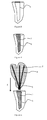
- les
figures 1 et 2 représentent, de manière schématique, en coupe, des structures de renfort pour reconstitution dentaire corono-radiculaire selon deux modes de réalisation, - les
figures 3 à 6 représentent, de manière schématique et en coupe, différentes étapes d'un procédé de réalisation d'une reconstitution corono-radiculaire, selon un mode de réalisation, - les
figures 7 et8 représentent, de manière schématique et en coupe, différentes étapes d'un procédé de réalisation d'une reconstitution corono-radiculaire, selon un autre mode de réalisation, - la
figure 9 représente, de manière schématique, en coupe, deux structures de renfort dans un canal dentaire, - les
figures 10 et 11 représentent, de manière schématique, et en coupe, des structures de renfort dans un canal dentaire selon un autre mode de réalisation de l'invention. - Comme illustré à la
figure 1 , la structure de renfort 1 pour reconstitution dentaire corono-radiculaire comprend un faisceau de tiges 2. - Par faisceau de tiges, on entend un ensemble d'éléments longilignes liés ensemble dans le sens de la longueur.
- Le faisceau comprend au moins deux tiges 2. Préférentiellement, le faisceau comprend de 2 à 10 tiges, et encore, plus préférentiellement, de 3 à 10 tiges et, encore plus préférentiellement, de 3 à 5 tiges.
- Le nombre de tiges est, avantageusement, inversement proportionnel au diamètre des tiges.
- Les tiges 2 sont, avantageusement, de longueur identique. Elles forment ainsi un faisceau de forme homogène.
- Comme représenté sur la
figure 2 , les tiges 2 peuvent être de longueurs différentes, leurs extrémités étant décalées. - Les tiges 2 sont avantageusement flexibles pour pouvoir s'insérer facilement dans le canal dentaire et s'adapter à la morphologie complexe des canaux dentaires.
- Par flexible, on entend un élément souple, qui peut se courber facilement.
- Sur la
figure 1 , les tiges 2 sont droites : elles sont représentées de manière schématique. En réalité, comme elles sont flexibles, elles peuvent présenter une forme courbe. - Les tiges 2 ont un très faible diamètre. Par faible diamètre, on entend un diamètre inférieur ou égal à 1 mm, et de préférence inférieur ou égal à 0,8mm encore plus préférentiellement il est inférieur ou égal à 0,5mm.
- De préférence, le diamètre des tiges 2 est compris entre 0,1mm et 0,8mm, et, encore plus préférentiellement, il est compris entre 0,1 mm et 0,5mm.
- Les tiges 2 peuvent s'adapter ainsi à de nombreuses structures canalaires, même à des structures très exiguës.
- Selon un mode de réalisation, les tiges 2 ont un diamètre identique, c'est-à-dire que toutes les tiges ont à peu près le même diamètre à 0,05 mm près.
- Selon un autre mode de réalisation, les tiges 2 ont une section croissante depuis le centre du faisceau vers la périphérie du faisceau.
- Par exemple, la tige, en position centrale du faisceau, peut avoir un diamètre de 0,8mm et les tiges en position périphérique peuvent avoir un diamètre de 0,3mm.
- Selon un autre exemple, le faisceau peut être formé de deux tiges de 0,5 mm de diamètre, de deux tiges de 0,3 mm de diamètre et de deux tiges de 0,15 mm de diamètre.
- La totalité de la partie coronaire est, avantageusement, renforcée.
- Le diamètre de la tige peut aussi varier tout au long de sa longueur et la tige peut avoir une géométrie cylindro-conique, cylindrique à étage, en double conicité ou encore avec une conicité variable sur toute sa longueur.
- Selon un autre mode de réalisation, les tiges 2 peuvent avoir une section décroissante depuis le centre du faisceau vers la périphérie du faisceau.
- Les tiges 2 sont en matériau composite : les tiges 2 sont formées d'au moins une fibre 3 enrobée d'une matrice polymère 4.
- Avantageusement, la matrice polymère sera choisie par l'homme du métier. Elle doit permettre d'associer solidement les fibres entre elles pour former une tige composite fibrée résistante.
- Préférentiellement, chaque tige 2 comporte plusieurs fibres 3 indépendantes les unes des autres ou sous la forme d'un assemblage de fibres, les fibres pouvant être, par exemple, torsadées et éventuellement floquées, recouverte d'un revêtement.
- Les fibres sont, de préférence, des fibres longues unidirectionnelles. Les fibres 3 d'une même tige 2 sont enrobées dans une matrice polymère 4.
- Chaque tige 2 est formée de fibres 3 enrobées dans une matrice polymère 4. Les tiges 2 sont, de préférence, individuellement, entièrement polymérisées de manière à former des tiges 2 flexibles indépendantes les unes des autres.
- Les fibres 3 jouent le rôle de renfort au sein des tiges 2, dans leur grand axe (axe AA' de la
figure 1 ). - Les fibres 3 des tiges 2 peuvent être de nature identique ou différente, au sein d'une même tige 2.
- Les fibres 3 peuvent de nature identique ou différente d'une tige 2 à l'autre.
- On peut utiliser n'importe quelle sorte de fibre pourvue qu'elle possède un revêtement de surface (ou « coating » en anglais) compatible avec la résine d'assemblage utilisée. Il peut s'agir de fibres manufacturées artificielles, comme des fibres siliceuses, des fibres de carbone, ou encore des fibres organiques (du type poly(p-phénylènetéréphtalamide) (PPD-T), aramide, nylon...) ou même des fibres naturelles.
- Comme représenté sur les
figures 1 et 2 , les tiges 2 sont assemblées, connectées mécaniquement par un élément d'assemblage 5. Toutes les tiges 2 sont maintenues ensemble par l'élément d'assemblage 5. L'élément d'assemblage 5 est configuré pour grouper la pluralité de tiges 2. - L'élément d'assemblage 5 recouvre partiellement la longueur des tiges 2 et est configuré pour tenir mécaniquement les tiges ensemble et pour laisser libre une partie de la longueur des tiges 2. Chaque tige présente une extrémité libre mobile en flexion par rapport aux autres tiges du faisceau de tiges. Avantageusement, chaque tige présente une extrémité libre mobile en flexion et en translation par rapport aux autres tiges du faisceau de tiges. Les tiges peuvent aussi glisser librement les unes par rapport aux autres selon leur grand axe, tout en étant freinées par leur frottement réciproque.
- Chaque tige présente, avantageusement, une mobilité dans les trois dimensions de l'espace.
- Le moyen d'assemblage 5 est disposé de manière à ce qu'au moins la moitié de la longueur des tiges 2 ne soit pas solidarisée par le moyen d'assemblage 5. L'élément d'assemblage 5 est, par exemple, positionné dans le premier tiers de la longueur du faisceau de tiges 2, de manière à permettre, autoriser la flexion et le glissement axial d'une tige par rapport à l'autre.
- Préférentiellement, l'élément d'assemblage 5 est disposé à une des extrémités du faisceau de tiges 2, pour entraver, au minimum, la liberté de flexion des tiges 2 relativement les unes par rapport aux autres.
- Par extrémité, on entend que l'élément d'assemblage 5 est positionné sur le premier quart de la longueur de la tige.
- Les tiges 2 sont maintenues d'un seul côté de manière à former un faisceau évasé. Par faisceau évasé, on entend un faisceau de tiges ayant la forme d'un bouquet, c'est-à-dire que la section du faisceau de tiges 2 au niveau de l'élément d'assemblage est strictement inférieure à la section du faisceau de tiges au niveau de l'extrémité libre, i.e. l'extrémité opposée à l'élément d'assemblage 5.
- Cependant les tiges peuvent être assemblées de façon circulaire, ovale ou selon une section plane, en fonction de la forme que lui donnera l'élément d'assemblage 5.
- Les tiges peuvent être solidarisées à leur extrémité mais les extrémités peuvent ne pas coïncider, par exemple, dans le cas de tiges 2 de longueurs différentes.
- Encore plus préférentiellement, l'élément d'assemblage 5 est positionné sur le bout des tiges, le bord extrême des tiges, c'est-à-dire que les tiges ne dépassent que d'un côté de l'élément d'assemblage 5.
- Préférentiellement, l'élément d'assemblage 5 est en résine composite.
- La résine est choisie parmi les résines méthacrylate, poly éther éther cétone et époxide.
- La résine peut contenir des additifs, sous forme de colorants minéraux ou organiques, ainsi que des particules microniques ou nanométriques destinées à en modifier la consistance ou les performances mécaniques.
- Par exemple, les tiges 2 sont maintenues par un manchon en résine composite polymérisée. Par manchon, on entend une pièce cylindrique ouverte au moins en une de ces deux extrémités.
- L'élément d'assemblage 5 peut être, simplement, réalisé par un collage des extrémités des tiges avec une colle composite. Cette technique est, préférentiellement, choisie lorsque les extrémités des tiges sont décalées.
- On décale les extrémités des tiges, dans l'élément d'assemblage 5, lorsqu'un apex fin, pointu est recherché pour le faisceau de tiges.
- L'élément d'assemblage 5 est configuré pour maintenir les tiges 2 ensemble lors de leur manipulation. Il est également configuré de telle sorte qu'il est possible de retirer des tiges 2 une à une ou par petite quantité dans le cas où la structure d'accueil du faisceau de tiges est de dimension inférieure au faisceau de tiges.
- Lorsqu'une ou plusieurs tiges sont retirées, l'élément d'assemblage continue à maintenir les fibres restantes. L'énergie pour arracher une tige du faisceau est inférieure à l'énergie nécessaire pour ouvrir, ou casser, l'élément d'assemblage 5.
- La taille du faisceau de tiges 2 est adaptable en fonction des besoins.
- Dans un mode préférentiel de l'invention, le moyen d'assemblage 5 n'empêche pas les tiges 2 de glisser les unes par rapport aux autres sur au moins un dixième de leur longueur et il les bloque ou les retient au-delà de cette distance. Par exemple, les tiges peuvent glisser les unes par rapport aux autres selon leur grand axe (axe AA' de la
figure 1 ). Les tiges 2 peuvent se croiser au sein de la structure. - Avantageusement, l'élément d'assemblage 5 n'empêche pas les tiges 2, aussi appelées micro-tenons, de se déplacer entre elles dans les trois dimensions.
- Comme représenté sur les
figures 3 à 5 , le procédé de réalisation d'une reconstitution dentaire corono-radiculaire 9, sur un modèle de laboratoire, par exemple un moule, comprend les étapes successives suivantes : - 1) remplir au moins partiellement un canal dentaire 6 du modèle de laboratoire avec une première résine composite 7,
- 2) fournir la structure de renfort 1 décrite précédemment, imprégnée avec une deuxième résine composite 8,
- 3) insérer la structure de renfort 1 dans le canal dentaire 6,
- 4) polymériser les résines composites 7, 8 de manière à obtenir une reconstitution corono-radiculaire 9.
- La
figure 3 représente un canal radiculaire 6. Il s'agit d'une cavité. Le procédé peut être réalisé sur tout modèle de laboratoire présentant une cavité. - Lors de l'étape 1), le canal radiculaire 6, ou la cavité, est rempli d'une première résine composite 7 (
figure 4 ). Préférentiellement, il est entièrement rempli de résine. - La structure de renfort 1 est imprégnée d'une deuxième résine composite 8 (étape 2). Préférentiellement, la structure de renfort 1 est imprégnée à saturation, c'est-à-dire qu'au moins les tiges 2 de la structure de renfort 1 sont entièrement recouvertes par la première résine composite 8 (
figure 5 ). - Préférentiellement, la première résine composite 7 et la deuxième résine composite 8 sont identiques, c'est-à-dire qu'elles sont de même nature, il s'agit de la même résine. Encore plus préférentiellement, la première résine composite 7 et la deuxième résine composite 8 sont une seule et même résine de collage. Ceci permet un meilleur maintien mécanique.
- Les résines sont polymérisables.
- Avantageusement, la même colle composite est utilisée pour la confection de la partie coronaire, de la partie corono-radiculaire ainsi que de la partie apicale de la reconstitution dentaire corono-radiculaire.
- Selon un autre mode de réalisation, la deuxième résine composite 8 englobant indépendamment chaque tige 2 peut être différente de la première résine composite 7.
- Lors de l'étape 3, la structure de renfort 1, imprégnée de la deuxième résine composite 8, est insérée dans le canal dentaire 6 (flèche F de la
figure 5 ). Préférentiellement, toutes les tiges 2 de la structure de renfort 1 sont maintenues par l'élément d'assemblage 5. L'élément d'assemblage 5 est positionné dans la partie apicale de la structure, de manière à être en contact avec l'alésage opéré avec le foret de préparation (figure 6 ). - L'élément d'assemblage 5 présente, avantageusement, la même géométrie que l'apex du foret d'alésage utilisé lors de la préparation du canal dentaire 6. L'élément d'assemblage 5 s'adapte ainsi parfaitement dans le canal dentaire 6. Une adaptation précise du tenon permet d'améliorer à la fois la rétention et le collage mais aussi l'écoulement des contraintes fonctionnelles.
- L'élément d'assemblage 5 et le faisceau de tiges 2, enrobées de résine, en contact intime avec les parois du canal dentaire, forment un ensemble mécaniquement compact et cohérent, réalisant ainsi une continuité volumique, participant à la répartition des contraintes sans rupture de charge et sans présenter de zones de concentration des contraintes à l'origine des fractures.
- Les tiges 2 de la structure de renfort 1 sont dispersées en continuité dans la totalité de la première résine composite 7 de reconstitution. La structure de renfort 1 s'adapte à la géométrie de la cavité par glissement des tiges 2 les unes par rapport aux autres.
- Lors de l'étape 4, la première résine composite 7 et la deuxième résine composite 8 sont polymérisées. Après polymérisation, les tiges 2 sont figées dans la reconstitution corono-radiculaire 9.
- La polymérisation permet de constituer une reconstitution dentaire corono-radiculaire 9 assurant sa rigidité par sa propre forme et l'architecture de ses renforts.
- La partie coronaire est, avantageusement, formée des mêmes tiges 2 que la partie radiculaire.
- La reconstitution dentaire corono-radiculaire 9, obtenue selon le procédé, est réalisée sans procéder à de rectification du canal dentaire 6 dans sa partie corono radiculaire, jusqu'au 2/3 de la partie coronaire. Le canal peut être instrumenté avec des alésoirs à conicité variable pour effectuer le traitement endodontique. A l'apex, la conicité est donc définie par cette instrumentalisation.
- De plus, elle a la même géométrie que l'apex du foret d'alésage utilisé lors de la préparation du canal dentaire 6 pour le traitement endodontique et s'adapte facilement aux particularités anatomiques des chambres pulpaires et des canaux dentaires.
- Avant l'étape de polymérisation, et comme représenté sur les
figures 6 à 8 , une deuxième structure 10 peut être déposée sur la première structure de renfort 1, les tiges 11 de la deuxième structure de renfort 10 s'enchevêtrant dans les tiges 2 de la première structure de renfort 1 par glissement. La deuxième structure de renfort 10 est insérée en coiffage de la première structure 1 (flèche F' de lafigure 7 ). La deuxième structure de renfort 10 s'adapte sur la première structure 1 par glissement contre les tiges 2 radiculaires pour constituer un réseau fibré pluridimensionnel. - La deuxième structure de renfort 10 est également formée d'un faisceau de tiges 11 en matériau composite : des fibres longues allongées dans le grand axe de chaque tige sont recouvertes d'un polymère entièrement polymérisé. Les tiges 11 sont indépendantes les unes des autres. Les tiges 11 de la deuxième structure de renfort 10 sont maintenues par un élément d'assemblage 12.
- Les tiges 11 de la deuxième structure de renfort 10 peuvent également être recouvertes d'une résine composite polymérisable avant d'être insérées en coiffage de la première structure de renfort 1. Préférentiellement, la résine composite est la même que celle recouvrant les tiges 2 de la première structure 1.
- Selon un autre mode de réalisation, les tiges 2 de la première structure de renfort 1 présentent une quantité suffisante de résine composite et il n'y a pas besoin de rajouter de la résine sur les tiges 11 de la deuxième structure de renfort 10 (cas de la représentation schématique de la
figure 7 ). - Un réseau de tiges 2, 11 enchevêtrées est obtenu (
figure 8 ). Les contraintes mécaniques sont mieux réparties et la structure est plus solide. - La reconstitution dentaire corono-radiculaire 9 obtenue par le procédé comprend au moins une structure de renfort 1, la structure de renfort 1 étant noyée dans au moins une résine composite polymérisée.
- Plus particulièrement, la structure en matériau composite à renfort de fibres pour reconstitution dentaire corono-radiculaire comprend un faisceau de tiges indépendantes les unes des autres. Une portion des tiges est solidarisée par un élément d'assemblage.
- La structure de renfort et la résine forment une structure autoportante assurant la rigidité de la reconstitution.
- Selon un autre mode de réalisation, la reconstitution dentaire comprend deux structures de renfort 1, 10, disposées l'une au-dessus de l'autre, les tiges 2, 11 des deux structures étant enchevêtrées. La structure de renfort 10 additionnelle, la structure de renfort coronaire, est en complément de la première structure de renfort 1 radiculaire.
- Selon un autre mode de réalisation, la reconstitution dentaire peut aussi comprendre des structures de renforts 1, 10 insérées côte à côte dans un même canal dentaire 6 (
figure 9 ). Les deux structures de renfort 1, 10 sont insérées dans un même canal dentaire pour former une même reconstitution dentaire corono-radiculaire. Les éléments d'assemblage 5, 12 de chaque structure de renfort 1, 10 sont disposés côte à côte dans le canal et les tiges 2, 11 des deux structures de renfort s'entremêlent. - Le nombre de tiges et/ou le diamètre des tiges est adapté en fonction de la forme et de la taille de la cavité destinée à recevoir la structure de renfort.
- Les tiges 2, 11 de chaque structure sont indépendantes les unes des autres et s'adaptent par flexion à la morphologie naturelle d'un canal dentaire sans alésage à une forme définie.
- Selon un mode de réalisation préférentiel, l'élément d'assemblage 5 est une gaine thermo-rétractable. Par thermo-rétractable, on entend un élément possédant la propriété de se rétracter sous l'action de la chaleur. Par gaine, on entend un étui, un fourreau pouvant s'adapter à la forme, dimension du faisceau de tiges.
- Préférentiellement, et comme représenté sur les
figures 10 et 11 , lors de l'étape 3) du procédé de réalisation de la reconstitution dentaire corono-radiculaire décrit ci-dessus, les structures de renfort 1, 10, munies de gaine thermo-rétractable, sont insérées dans le canal : les tiges 2, 11 se situent au niveau de la partie radiculaire du canal et l'élément d'assemblage 5, 12 est positionné au-dessus de la partie coronaire. L'élément d'assemblage est en position distale par rapport à la partie apicale du canal dentaire. - L'élément d'assemblage 5 joue, avantageusement, le rôle de préhenseur.
- Avant l'étape de polymérisation (étape 4 du procédé décrit ci-dessus), une deuxième structure de renfort 10 peut être déposée à côté de la première structure de renfort 1, dans le canal dentaire 6 (
figure 11 ). - Dans cette configuration (élément d'assemblage disposé à l'opposé de la partie apicale du canal dentaire), l'élément d'assemblage 5, 12 est éliminé à la fin du procédé de réalisation de la reconstitution dentaire corono-radiculaire.
- Selon d'autres variantes, ce positionnement des structures de renfort peut également être réalisé avec un faisceau de tiges muni d'un élément d'assemblage d'une autre nature. Il peut s'agir d'une simple gaine, d'un manchon, ou encore de tout élément permettant de maintenir les tiges ensemble, sous la forme d'un faisceau. L'élément d'assemblage peut initier toute forme au faisceau de tiges, aplaties dans le même plan, ovoïde, circulaire, triangulaire. Il n'existe pas de limite aux formes possibles.
- Le nombre de structures de renfort 1, 10 insérées dans le canal dentaire dépend de la taille dudit canal. La
figure 10 représente, par exemple, un canal dans lequel est inséré une seule structure de renfort. Lafigure 11 représente un canal dans lequel deux structures de renfort sont insérées côte à côte. - De 1 à 10 structures de renfort peuvent ainsi être insérées dans le canal dentaire.
- La reconstitution corono-radiculaire peut être réalisée, par exemple, sur des modèles dentaires de laboratoire.
- La reconstitution dentaire corono-radiculaire épouse et respecte les particularités anatomiques et physiologiques du canal radiculaire.
- La ou les structures de renfort se prolongent dans tout le volume de la partie radiculaire et de la partie coronaire supra gingivale de la reconstitution dentaire corono-radiculaire. Elles permettent de renforcer en continuité la totalité du matériau de la reconstitution constituant la partie coronaire mais aussi la partie radiculaire.
Claims (15)
- Structure de renfort (1) pour reconstitution dentaire corono-radiculaire comprenant :- une pluralité de tiges (2) ayant des diamètres allant de 0,1 mm à 0,5mm,- un élément d'assemblage (5) configuré pour grouper la pluralité de tiges (2) de manière à former un faisceau de tiges, ledit élément d'assemblage (5) recouvrant partiellement la longueur des tiges (2) de manière à ce que chaque tige présente une extrémité libre mobile en flexion par rapport aux autres tiges du faisceau de tiges.
- Structure de renfort selon la revendication 1, caractérisée en ce que l'élément d'assemblage (5) est disposé à une des extrémités du faisceau de tiges (2).
- Structure selon l'une des revendications 1 et 2, caractérisé en ce que chaque tige (2) est formée de fibres (3) enrobées dans une matrice polymère (4).
- Structure de renfort selon l'une des revendications 1 à 3, caractérisée en ce que l'élément d'assemblage (5) est en résine composite.
- Structure de renfort selon l'une quelconque des revendications 3 à 4, caractérisée en ce que les fibres (3) des tiges (2) sont de nature identique, au sein d'une même tige (2) ou d'une tige (2) à l'autre.
- Structure de renfort selon l'une quelconque des revendications 3 à 4, caractérisée en ce que les fibres (3) des tiges (2) sont de natures différentes, au sein d'une même tige (2) ou d'une tige (2) à l'autre.
- Structure de renfort selon l'une quelconque des revendications 1 à 6, caractérisée en ce que les tiges (2) ont le même diamètre.
- Structure de renfort selon l'une quelconque des revendications 1 à 6, caractérisée en ce que les tiges (2) ont un diamètre croissant depuis le centre du faisceau vers la périphérie du faisceau.
- Structure de renfort selon l'une quelconque des revendications 1 à 6, caractérisée en ce que les tiges (2) ont un diamètre décroissant depuis le centre du faisceau vers la périphérie du faisceau.
- Structure de renfort selon l'une quelconque des revendications 1 à 9, caractérisé en ce que le faisceau de tiges (2) comprend de 3 à 10 tiges.
- Procédé de réalisation d'une reconstitution dentaire corono-radiculaire, sur un modèle de laboratoire, comprenant les étapes successives suivantes :- remplir au moins partiellement un canal dentaire (6) du modèle de laboratoire avec une première résine composite (7),- fournir la structure de renfort (1), selon l'une quelconque des revendications 1 à 9, imprégnée avec une deuxième résine composite (8),- insérer la structure de renfort (1) imprégnée de la deuxième résine composite (8) dans le canal dentaire (6),- polymériser la première résine composite (7) et la deuxième résine composite (8) de manière à obtenir une reconstitution corono-radiculaire (9).
- Procédé de réalisation selon la revendication 11, caractérisé en ce que la première résine composite (7) et la deuxième résine composite (8) sont identiques.
- Procédé selon l'une des revendications 11 et 12, caractérisé en ce que, avant l'étape de polymérisation, une deuxième structure de renfort (10) est déposée sur la première structure de renfort (1), des tiges (11) de la deuxième structure de renfort (10) s'enchevêtrant dans les tiges (2) de la première structure de renfort (1) par glissement.
- Procédé selon l'une des revendications 11 et 12, caractérisé en ce que, avant l'étape de polymérisation, une deuxième structure de renfort (10) est déposée à côté de la première structure de renfort (1), dans le canal dentaire (6).
- Reconstitution dentaire corono-radiculaire obtenue par le procédé selon l'une quelconque des revendications 11 à 14.
Applications Claiming Priority (1)
| Application Number | Priority Date | Filing Date | Title |
|---|---|---|---|
| FR1400956A FR3020264B1 (fr) | 2014-04-23 | 2014-04-23 | Structure de renfort pour reconstitution dentaire corono-radiculaire, procede de realisation d'une reconstitution dentaire corono-radiculaire, reconstitution dentaire corono-radiculaire |
Publications (2)
| Publication Number | Publication Date |
|---|---|
| EP2937062A1 true EP2937062A1 (fr) | 2015-10-28 |
| EP2937062B1 EP2937062B1 (fr) | 2017-11-01 |
Family
ID=51014358
Family Applications (1)
| Application Number | Title | Priority Date | Filing Date |
|---|---|---|---|
| EP15164727.8A Active EP2937062B1 (fr) | 2014-04-23 | 2015-04-22 | Structure de renfort pour reconstitution dentaire corono-radiculaire, procédé de réalisation d'une reconstitution dentaire corono-radiculaire, reconstitution dentaire corono-radiculaire |
Country Status (4)
| Country | Link |
|---|---|
| US (1) | US9839493B2 (fr) |
| EP (1) | EP2937062B1 (fr) |
| CA (1) | CA2888842C (fr) |
| FR (1) | FR3020264B1 (fr) |
Cited By (1)
| Publication number | Priority date | Publication date | Assignee | Title |
|---|---|---|---|---|
| EP3470014A1 (fr) * | 2017-10-12 | 2019-04-17 | Bruno Clunet-Coste | Reconstitution dentaire corono-radiculaire, procede de realisation d'une telle reconstitution et procede de gravure d'une telle reconstitution dentaire |
Families Citing this family (1)
| Publication number | Priority date | Publication date | Assignee | Title |
|---|---|---|---|---|
| FR3058886B1 (fr) | 2016-11-22 | 2022-02-11 | Bernard Maneuf | Structure de renfort pour reconstitution dentaire corono-radiculaire, procede de realisation d’une reconstitution dentaire corono-radiculaire, reconstitution dentaire corono-radiculaire. |
Citations (12)
| Publication number | Priority date | Publication date | Assignee | Title |
|---|---|---|---|---|
| GB1255875A (en) | 1968-11-21 | 1971-12-01 | Louyot Comptoir Lyon Alemand | Improvements in and relating to dental pivots |
| CH562605A5 (en) | 1974-03-21 | 1975-06-13 | Spang Herbert | Steel anchor for artificial tooth crown - lower threaded spindle carries segmented flanges |
| FR2588181A1 (fr) | 1985-10-07 | 1987-04-10 | Jean Barbe | Nouvelles protheses endobuccales en matieres composites |
| DE3825601A1 (de) | 1988-07-28 | 1989-03-09 | Strobl Walter | Intrakanalaer zu verankernder zahnhartsubstanzaufbau |
| US4936776A (en) | 1988-07-05 | 1990-06-26 | Kwiatkowski Stephen J | Dental product and method utilizing translucent material |
| EP0432001A1 (fr) | 1989-11-20 | 1991-06-12 | Marc Reynaud | Tenon d'ancrage dentaire physiologique en matériau composite et son procédé de fabrication |
| FR2669211A2 (fr) * | 1989-03-02 | 1992-05-22 | Bernadat Georges | Prothese de reconstitution d'une dent devitalisee et appareil pour son implantation. |
| FR2730627A1 (fr) * | 1995-02-17 | 1996-08-23 | Marc Reynaud | Renfort dentaire autobloquant |
| FR2753365A1 (fr) | 1996-09-17 | 1998-03-20 | Billet Gilles | Insert endodontique d'obturation canalaire dentaire preimpregne a renforts de fibres |
| US5915970A (en) * | 1993-09-27 | 1999-06-29 | Tru-Flex Post Systems, Inc. | Flexible post in a dental post and core system |
| WO1999045859A1 (fr) * | 1998-03-10 | 1999-09-16 | Sun Medical Co., Ltd. | Pivot dentaire, renforcement de materiau de noyau pour la fabrication d'un pivot dentaire et kit permettant la fabrication d'un pivot dentaire |
| US20110294095A1 (en) * | 2009-02-18 | 2011-12-01 | Adm A.S. | Tooth stump structure, production method and design thereof |
Family Cites Families (2)
| Publication number | Priority date | Publication date | Assignee | Title |
|---|---|---|---|---|
| US6371763B1 (en) * | 1997-11-28 | 2002-04-16 | Robert J. Sicurelli, Jr. | Flexible post in a dental post and core system |
| FI980528A7 (fi) * | 1998-03-09 | 1999-09-10 | Bioxid Oy | Uusi prepreg |
-
2014
- 2014-04-23 FR FR1400956A patent/FR3020264B1/fr active Active
-
2015
- 2015-04-22 EP EP15164727.8A patent/EP2937062B1/fr active Active
- 2015-04-22 CA CA2888842A patent/CA2888842C/fr active Active
- 2015-04-23 US US14/694,117 patent/US9839493B2/en active Active
Patent Citations (12)
| Publication number | Priority date | Publication date | Assignee | Title |
|---|---|---|---|---|
| GB1255875A (en) | 1968-11-21 | 1971-12-01 | Louyot Comptoir Lyon Alemand | Improvements in and relating to dental pivots |
| CH562605A5 (en) | 1974-03-21 | 1975-06-13 | Spang Herbert | Steel anchor for artificial tooth crown - lower threaded spindle carries segmented flanges |
| FR2588181A1 (fr) | 1985-10-07 | 1987-04-10 | Jean Barbe | Nouvelles protheses endobuccales en matieres composites |
| US4936776A (en) | 1988-07-05 | 1990-06-26 | Kwiatkowski Stephen J | Dental product and method utilizing translucent material |
| DE3825601A1 (de) | 1988-07-28 | 1989-03-09 | Strobl Walter | Intrakanalaer zu verankernder zahnhartsubstanzaufbau |
| FR2669211A2 (fr) * | 1989-03-02 | 1992-05-22 | Bernadat Georges | Prothese de reconstitution d'une dent devitalisee et appareil pour son implantation. |
| EP0432001A1 (fr) | 1989-11-20 | 1991-06-12 | Marc Reynaud | Tenon d'ancrage dentaire physiologique en matériau composite et son procédé de fabrication |
| US5915970A (en) * | 1993-09-27 | 1999-06-29 | Tru-Flex Post Systems, Inc. | Flexible post in a dental post and core system |
| FR2730627A1 (fr) * | 1995-02-17 | 1996-08-23 | Marc Reynaud | Renfort dentaire autobloquant |
| FR2753365A1 (fr) | 1996-09-17 | 1998-03-20 | Billet Gilles | Insert endodontique d'obturation canalaire dentaire preimpregne a renforts de fibres |
| WO1999045859A1 (fr) * | 1998-03-10 | 1999-09-16 | Sun Medical Co., Ltd. | Pivot dentaire, renforcement de materiau de noyau pour la fabrication d'un pivot dentaire et kit permettant la fabrication d'un pivot dentaire |
| US20110294095A1 (en) * | 2009-02-18 | 2011-12-01 | Adm A.S. | Tooth stump structure, production method and design thereof |
Cited By (3)
| Publication number | Priority date | Publication date | Assignee | Title |
|---|---|---|---|---|
| EP3470014A1 (fr) * | 2017-10-12 | 2019-04-17 | Bruno Clunet-Coste | Reconstitution dentaire corono-radiculaire, procede de realisation d'une telle reconstitution et procede de gravure d'une telle reconstitution dentaire |
| FR3072274A1 (fr) * | 2017-10-12 | 2019-04-19 | Bruno Clunet Coste | Reconstitution dentaire corono-radiculaire, procede de realisation d’une telle reconstitution et procede de gravure d’une telle reconstitution dentaire |
| US11364096B2 (en) | 2017-10-12 | 2022-06-21 | Bruno Clunet-Coste | Crown and root dental restoration, method for performing one such restoration and method for etching one such dental restoration |
Also Published As
| Publication number | Publication date |
|---|---|
| US20150305829A1 (en) | 2015-10-29 |
| CA2888842A1 (fr) | 2015-10-23 |
| FR3020264B1 (fr) | 2022-12-30 |
| CA2888842C (fr) | 2022-08-30 |
| EP2937062B1 (fr) | 2017-11-01 |
| US9839493B2 (en) | 2017-12-12 |
| FR3020264A1 (fr) | 2015-10-30 |
Similar Documents
| Publication | Publication Date | Title |
|---|---|---|
| FR3072274B1 (fr) | Reconstitution dentaire corono-radiculaire, procede de realisation d’une telle reconstitution et procede de gravure d’une telle reconstitution dentaire | |
| EP2843193B1 (fr) | Aube composite fabriquée par addition de matériel et procédé de fabrication correspondant | |
| EP2843192B1 (fr) | Aube composite réalisée par fabrication additive et procédé de fabrication associé | |
| EP2445705B1 (fr) | Procédé de fabrication de bielles composites | |
| EP1511372B1 (fr) | Nouvel ensemble de coupe et nouveau filament de coupe pour un appareil de coupe de vegetaux | |
| WO2010007257A1 (fr) | Dispositif pour injecter dans un logement canalaire un materiau de remplissage en phase fluide. | |
| FR2753365A1 (fr) | Insert endodontique d'obturation canalaire dentaire preimpregne a renforts de fibres | |
| FR2643812A1 (fr) | Procede de renforcement d'une dent devitalisee et moyen pour sa mise en oeuvre | |
| FR2935162A1 (fr) | Element de fixation male composite-metal | |
| FR2746867A1 (fr) | Assemblage entre des barres ou des tubes en materiaux composites renforces par des fibres | |
| EP2937062B1 (fr) | Structure de renfort pour reconstitution dentaire corono-radiculaire, procédé de réalisation d'une reconstitution dentaire corono-radiculaire, reconstitution dentaire corono-radiculaire | |
| EP2265146B1 (fr) | Dispositif applicateur d'un produit cosmetique fluide ou pateux, typiquement du mascara | |
| EP3544543B1 (fr) | Structure de renfort pour reconstitution dentaire corono-radiculaire et son procede d'utilisation sur un modele de laboratoire. | |
| FR3020749A1 (fr) | Brosse cosmetique torsadee | |
| EP0098825A1 (fr) | Fibres de renforcement de matériaux moulables à liant hydraulique ou non et leur fabrication | |
| EP0538088B1 (fr) | Rotor multipale, notamment pour hélice arrière anticouple d'hélicoptère et procédé pour sa réalisation | |
| EP1440668B1 (fr) | Instrument dentaire pour l'extraction d'un objet d'un canal radiculaire | |
| EP2083652B1 (fr) | Applicateur de produit cosmetique | |
| EP4158221B1 (fr) | Dispositif de jonction de bande transporteuse a câbles muni d'elements de blocage de câble | |
| WO2010031957A1 (fr) | Brosse pour un applicateur de mascara comprenant des dents formant des rangs transversaux | |
| EP3119239B1 (fr) | Applicateur pour produit cosmétique et ensemble applicateur associé | |
| EP1121492A1 (fr) | Deviateur pour cable de hauban | |
| EP0901550A1 (fr) | Vibrateur a aiguille portatif | |
| EP1716819A1 (fr) | Ancrage canalaire dentaire anatomique et préfabriqué | |
| FR2861287A1 (fr) | Ancrage canalaire dentaire anatomique profile prefabrique |
Legal Events
| Date | Code | Title | Description |
|---|---|---|---|
| PUAI | Public reference made under article 153(3) epc to a published international application that has entered the european phase |
Free format text: ORIGINAL CODE: 0009012 |
|
| AK | Designated contracting states |
Kind code of ref document: A1 Designated state(s): AL AT BE BG CH CY CZ DE DK EE ES FI FR GB GR HR HU IE IS IT LI LT LU LV MC MK MT NL NO PL PT RO RS SE SI SK SM TR |
|
| AX | Request for extension of the european patent |
Extension state: BA ME |
|
| 17P | Request for examination filed |
Effective date: 20160428 |
|
| RBV | Designated contracting states (corrected) |
Designated state(s): AL AT BE BG CH CY CZ DE DK EE ES FI FR GB GR HR HU IE IS IT LI LT LU LV MC MK MT NL NO PL PT RO RS SE SI SK SM TR |
|
| GRAP | Despatch of communication of intention to grant a patent |
Free format text: ORIGINAL CODE: EPIDOSNIGR1 |
|
| INTG | Intention to grant announced |
Effective date: 20170522 |
|
| RAP1 | Party data changed (applicant data changed or rights of an application transferred) |
Owner name: CLUNET-COSTE, BRUNO Owner name: COLLOMBIN, ANDRE Owner name: MANEUF, BERNARD |
|
| RIN1 | Information on inventor provided before grant (corrected) |
Inventor name: CLUNET-COSTE, BRUNO Inventor name: MANEUF, BERNARD Inventor name: COLLOMBIN, ANDRE |
|
| GRAS | Grant fee paid |
Free format text: ORIGINAL CODE: EPIDOSNIGR3 |
|
| GRAA | (expected) grant |
Free format text: ORIGINAL CODE: 0009210 |
|
| AK | Designated contracting states |
Kind code of ref document: B1 Designated state(s): AL AT BE BG CH CY CZ DE DK EE ES FI FR GB GR HR HU IE IS IT LI LT LU LV MC MK MT NL NO PL PT RO RS SE SI SK SM TR |
|
| REG | Reference to a national code |
Ref country code: GB Ref legal event code: FG4D Free format text: NOT ENGLISH |
|
| REG | Reference to a national code |
Ref country code: CH Ref legal event code: EP Ref country code: AT Ref legal event code: REF Ref document number: 941231 Country of ref document: AT Kind code of ref document: T Effective date: 20171115 |
|
| REG | Reference to a national code |
Ref country code: IE Ref legal event code: FG4D Free format text: LANGUAGE OF EP DOCUMENT: FRENCH |
|
| REG | Reference to a national code |
Ref country code: DE Ref legal event code: R096 Ref document number: 602015005664 Country of ref document: DE |
|
| REG | Reference to a national code |
Ref country code: NL Ref legal event code: MP Effective date: 20171101 |
|
| REG | Reference to a national code |
Ref country code: LT Ref legal event code: MG4D |
|
| REG | Reference to a national code |
Ref country code: AT Ref legal event code: MK05 Ref document number: 941231 Country of ref document: AT Kind code of ref document: T Effective date: 20171101 |
|
| REG | Reference to a national code |
Ref country code: FR Ref legal event code: PLFP Year of fee payment: 4 |
|
| PG25 | Lapsed in a contracting state [announced via postgrant information from national office to epo] |
Ref country code: NL Free format text: LAPSE BECAUSE OF FAILURE TO SUBMIT A TRANSLATION OF THE DESCRIPTION OR TO PAY THE FEE WITHIN THE PRESCRIBED TIME-LIMIT Effective date: 20171101 Ref country code: SE Free format text: LAPSE BECAUSE OF FAILURE TO SUBMIT A TRANSLATION OF THE DESCRIPTION OR TO PAY THE FEE WITHIN THE PRESCRIBED TIME-LIMIT Effective date: 20171101 Ref country code: LT Free format text: LAPSE BECAUSE OF FAILURE TO SUBMIT A TRANSLATION OF THE DESCRIPTION OR TO PAY THE FEE WITHIN THE PRESCRIBED TIME-LIMIT Effective date: 20171101 Ref country code: FI Free format text: LAPSE BECAUSE OF FAILURE TO SUBMIT A TRANSLATION OF THE DESCRIPTION OR TO PAY THE FEE WITHIN THE PRESCRIBED TIME-LIMIT Effective date: 20171101 Ref country code: ES Free format text: LAPSE BECAUSE OF FAILURE TO SUBMIT A TRANSLATION OF THE DESCRIPTION OR TO PAY THE FEE WITHIN THE PRESCRIBED TIME-LIMIT Effective date: 20171101 Ref country code: NO Free format text: LAPSE BECAUSE OF FAILURE TO SUBMIT A TRANSLATION OF THE DESCRIPTION OR TO PAY THE FEE WITHIN THE PRESCRIBED TIME-LIMIT Effective date: 20180201 |
|
| PG25 | Lapsed in a contracting state [announced via postgrant information from national office to epo] |
Ref country code: HR Free format text: LAPSE BECAUSE OF FAILURE TO SUBMIT A TRANSLATION OF THE DESCRIPTION OR TO PAY THE FEE WITHIN THE PRESCRIBED TIME-LIMIT Effective date: 20171101 Ref country code: RS Free format text: LAPSE BECAUSE OF FAILURE TO SUBMIT A TRANSLATION OF THE DESCRIPTION OR TO PAY THE FEE WITHIN THE PRESCRIBED TIME-LIMIT Effective date: 20171101 Ref country code: GR Free format text: LAPSE BECAUSE OF FAILURE TO SUBMIT A TRANSLATION OF THE DESCRIPTION OR TO PAY THE FEE WITHIN THE PRESCRIBED TIME-LIMIT Effective date: 20180202 Ref country code: BG Free format text: LAPSE BECAUSE OF FAILURE TO SUBMIT A TRANSLATION OF THE DESCRIPTION OR TO PAY THE FEE WITHIN THE PRESCRIBED TIME-LIMIT Effective date: 20180201 Ref country code: LV Free format text: LAPSE BECAUSE OF FAILURE TO SUBMIT A TRANSLATION OF THE DESCRIPTION OR TO PAY THE FEE WITHIN THE PRESCRIBED TIME-LIMIT Effective date: 20171101 Ref country code: AT Free format text: LAPSE BECAUSE OF FAILURE TO SUBMIT A TRANSLATION OF THE DESCRIPTION OR TO PAY THE FEE WITHIN THE PRESCRIBED TIME-LIMIT Effective date: 20171101 Ref country code: IS Free format text: LAPSE BECAUSE OF FAILURE TO SUBMIT A TRANSLATION OF THE DESCRIPTION OR TO PAY THE FEE WITHIN THE PRESCRIBED TIME-LIMIT Effective date: 20180301 |
|
| PG25 | Lapsed in a contracting state [announced via postgrant information from national office to epo] |
Ref country code: DK Free format text: LAPSE BECAUSE OF FAILURE TO SUBMIT A TRANSLATION OF THE DESCRIPTION OR TO PAY THE FEE WITHIN THE PRESCRIBED TIME-LIMIT Effective date: 20171101 Ref country code: CY Free format text: LAPSE BECAUSE OF FAILURE TO SUBMIT A TRANSLATION OF THE DESCRIPTION OR TO PAY THE FEE WITHIN THE PRESCRIBED TIME-LIMIT Effective date: 20171101 Ref country code: EE Free format text: LAPSE BECAUSE OF FAILURE TO SUBMIT A TRANSLATION OF THE DESCRIPTION OR TO PAY THE FEE WITHIN THE PRESCRIBED TIME-LIMIT Effective date: 20171101 Ref country code: SK Free format text: LAPSE BECAUSE OF FAILURE TO SUBMIT A TRANSLATION OF THE DESCRIPTION OR TO PAY THE FEE WITHIN THE PRESCRIBED TIME-LIMIT Effective date: 20171101 Ref country code: CZ Free format text: LAPSE BECAUSE OF FAILURE TO SUBMIT A TRANSLATION OF THE DESCRIPTION OR TO PAY THE FEE WITHIN THE PRESCRIBED TIME-LIMIT Effective date: 20171101 |
|
| REG | Reference to a national code |
Ref country code: DE Ref legal event code: R097 Ref document number: 602015005664 Country of ref document: DE |
|
| PG25 | Lapsed in a contracting state [announced via postgrant information from national office to epo] |
Ref country code: SM Free format text: LAPSE BECAUSE OF FAILURE TO SUBMIT A TRANSLATION OF THE DESCRIPTION OR TO PAY THE FEE WITHIN THE PRESCRIBED TIME-LIMIT Effective date: 20171101 Ref country code: IT Free format text: LAPSE BECAUSE OF FAILURE TO SUBMIT A TRANSLATION OF THE DESCRIPTION OR TO PAY THE FEE WITHIN THE PRESCRIBED TIME-LIMIT Effective date: 20171101 Ref country code: RO Free format text: LAPSE BECAUSE OF FAILURE TO SUBMIT A TRANSLATION OF THE DESCRIPTION OR TO PAY THE FEE WITHIN THE PRESCRIBED TIME-LIMIT Effective date: 20171101 Ref country code: PL Free format text: LAPSE BECAUSE OF FAILURE TO SUBMIT A TRANSLATION OF THE DESCRIPTION OR TO PAY THE FEE WITHIN THE PRESCRIBED TIME-LIMIT Effective date: 20171101 |
|
| PLBE | No opposition filed within time limit |
Free format text: ORIGINAL CODE: 0009261 |
|
| STAA | Information on the status of an ep patent application or granted ep patent |
Free format text: STATUS: NO OPPOSITION FILED WITHIN TIME LIMIT |
|
| PG25 | Lapsed in a contracting state [announced via postgrant information from national office to epo] |
Ref country code: MT Free format text: LAPSE BECAUSE OF FAILURE TO SUBMIT A TRANSLATION OF THE DESCRIPTION OR TO PAY THE FEE WITHIN THE PRESCRIBED TIME-LIMIT Effective date: 20171101 |
|
| 26N | No opposition filed |
Effective date: 20180802 |
|
| PG25 | Lapsed in a contracting state [announced via postgrant information from national office to epo] |
Ref country code: MC Free format text: LAPSE BECAUSE OF FAILURE TO SUBMIT A TRANSLATION OF THE DESCRIPTION OR TO PAY THE FEE WITHIN THE PRESCRIBED TIME-LIMIT Effective date: 20171101 Ref country code: SI Free format text: LAPSE BECAUSE OF FAILURE TO SUBMIT A TRANSLATION OF THE DESCRIPTION OR TO PAY THE FEE WITHIN THE PRESCRIBED TIME-LIMIT Effective date: 20171101 |
|
| REG | Reference to a national code |
Ref country code: IE Ref legal event code: MM4A |
|
| PG25 | Lapsed in a contracting state [announced via postgrant information from national office to epo] |
Ref country code: LU Free format text: LAPSE BECAUSE OF NON-PAYMENT OF DUE FEES Effective date: 20180422 |
|
| PG25 | Lapsed in a contracting state [announced via postgrant information from national office to epo] |
Ref country code: IE Free format text: LAPSE BECAUSE OF NON-PAYMENT OF DUE FEES Effective date: 20180422 |
|
| PG25 | Lapsed in a contracting state [announced via postgrant information from national office to epo] |
Ref country code: TR Free format text: LAPSE BECAUSE OF FAILURE TO SUBMIT A TRANSLATION OF THE DESCRIPTION OR TO PAY THE FEE WITHIN THE PRESCRIBED TIME-LIMIT Effective date: 20171101 |
|
| PG25 | Lapsed in a contracting state [announced via postgrant information from national office to epo] |
Ref country code: PT Free format text: LAPSE BECAUSE OF FAILURE TO SUBMIT A TRANSLATION OF THE DESCRIPTION OR TO PAY THE FEE WITHIN THE PRESCRIBED TIME-LIMIT Effective date: 20171101 |
|
| PG25 | Lapsed in a contracting state [announced via postgrant information from national office to epo] |
Ref country code: MK Free format text: LAPSE BECAUSE OF NON-PAYMENT OF DUE FEES Effective date: 20171101 Ref country code: HU Free format text: LAPSE BECAUSE OF FAILURE TO SUBMIT A TRANSLATION OF THE DESCRIPTION OR TO PAY THE FEE WITHIN THE PRESCRIBED TIME-LIMIT; INVALID AB INITIO Effective date: 20150422 |
|
| PG25 | Lapsed in a contracting state [announced via postgrant information from national office to epo] |
Ref country code: AL Free format text: LAPSE BECAUSE OF FAILURE TO SUBMIT A TRANSLATION OF THE DESCRIPTION OR TO PAY THE FEE WITHIN THE PRESCRIBED TIME-LIMIT Effective date: 20171101 |
|
| PGFP | Annual fee paid to national office [announced via postgrant information from national office to epo] |
Ref country code: BE Payment date: 20230427 Year of fee payment: 9 |
|
| REG | Reference to a national code |
Ref country code: BE Ref legal event code: MM Effective date: 20240430 |
|
| PG25 | Lapsed in a contracting state [announced via postgrant information from national office to epo] |
Ref country code: BE Free format text: LAPSE BECAUSE OF NON-PAYMENT OF DUE FEES Effective date: 20240430 |
|
| PG25 | Lapsed in a contracting state [announced via postgrant information from national office to epo] |
Ref country code: BE Free format text: LAPSE BECAUSE OF NON-PAYMENT OF DUE FEES Effective date: 20240430 |
|
| PGFP | Annual fee paid to national office [announced via postgrant information from national office to epo] |
Ref country code: DE Payment date: 20250429 Year of fee payment: 11 |
|
| PGFP | Annual fee paid to national office [announced via postgrant information from national office to epo] |
Ref country code: GB Payment date: 20250428 Year of fee payment: 11 |
|
| PGFP | Annual fee paid to national office [announced via postgrant information from national office to epo] |
Ref country code: FR Payment date: 20250428 Year of fee payment: 11 |
|
| PGFP | Annual fee paid to national office [announced via postgrant information from national office to epo] |
Ref country code: CH Payment date: 20250501 Year of fee payment: 11 |
|
| REG | Reference to a national code |
Ref country code: DE Ref legal event code: R081 Ref document number: 602015005664 Country of ref document: DE Owner name: BIO COMPOSANTS MEDICAUX, FR Free format text: FORMER OWNERS: CLUNET-COSTE, BRUNO, SAINT-ETIENNE-DE-CROSSEY, FR; MANEUF, BERNARD, VOIRON, FR; COLLOMBIN, ANDRE, VOIRON, FR |
|
| REG | Reference to a national code |
Ref country code: GB Ref legal event code: 732E Free format text: REGISTERED BETWEEN 20260129 AND 20260204 |