EP2937687A1 - Probeninjektor - Google Patents
Probeninjektor Download PDFInfo
- Publication number
- EP2937687A1 EP2937687A1 EP13865867.9A EP13865867A EP2937687A1 EP 2937687 A1 EP2937687 A1 EP 2937687A1 EP 13865867 A EP13865867 A EP 13865867A EP 2937687 A1 EP2937687 A1 EP 2937687A1
- Authority
- EP
- European Patent Office
- Prior art keywords
- sample
- detector
- flow path
- air layers
- loop
- Prior art date
- Legal status (The legal status is an assumption and is not a legal conclusion. Google has not performed a legal analysis and makes no representation as to the accuracy of the status listed.)
- Withdrawn
Links
Images


Classifications
-
- G—PHYSICS
- G01—MEASURING; TESTING
- G01N—INVESTIGATING OR ANALYSING MATERIALS BY DETERMINING THEIR CHEMICAL OR PHYSICAL PROPERTIES
- G01N30/00—Investigating or analysing materials by separation into components using adsorption, absorption or similar phenomena or using ion-exchange, e.g. chromatography or field flow fractionation
- G01N30/02—Column chromatography
- G01N30/04—Preparation or injection of sample to be analysed
- G01N30/16—Injection
- G01N30/20—Injection using a sampling valve
-
- G—PHYSICS
- G01—MEASURING; TESTING
- G01N—INVESTIGATING OR ANALYSING MATERIALS BY DETERMINING THEIR CHEMICAL OR PHYSICAL PROPERTIES
- G01N30/00—Investigating or analysing materials by separation into components using adsorption, absorption or similar phenomena or using ion-exchange, e.g. chromatography or field flow fractionation
- G01N30/02—Column chromatography
- G01N30/04—Preparation or injection of sample to be analysed
- G01N30/24—Automatic injection systems
-
- G—PHYSICS
- G01—MEASURING; TESTING
- G01N—INVESTIGATING OR ANALYSING MATERIALS BY DETERMINING THEIR CHEMICAL OR PHYSICAL PROPERTIES
- G01N35/00—Automatic analysis not limited to methods or materials provided for in any single one of groups G01N1/00 - G01N33/00; Handling materials therefor
- G01N35/08—Automatic analysis not limited to methods or materials provided for in any single one of groups G01N1/00 - G01N33/00; Handling materials therefor using a stream of discrete samples flowing along a tube system, e.g. flow injection analysis
-
- H—ELECTRICITY
- H01—ELECTRIC ELEMENTS
- H01J—ELECTRIC DISCHARGE TUBES OR DISCHARGE LAMPS
- H01J49/00—Particle spectrometers or separator tubes
- H01J49/02—Details
- H01J49/04—Arrangements for introducing or extracting samples to be analysed, e.g. vacuum locks; Arrangements for external adjustment of electron- or ion-optical components
- H01J49/0431—Arrangements for introducing or extracting samples to be analysed, e.g. vacuum locks; Arrangements for external adjustment of electron- or ion-optical components for liquid samples
-
- G—PHYSICS
- G01—MEASURING; TESTING
- G01N—INVESTIGATING OR ANALYSING MATERIALS BY DETERMINING THEIR CHEMICAL OR PHYSICAL PROPERTIES
- G01N30/00—Investigating or analysing materials by separation into components using adsorption, absorption or similar phenomena or using ion-exchange, e.g. chromatography or field flow fractionation
- G01N2030/009—Extraction
-
- G—PHYSICS
- G01—MEASURING; TESTING
- G01N—INVESTIGATING OR ANALYSING MATERIALS BY DETERMINING THEIR CHEMICAL OR PHYSICAL PROPERTIES
- G01N30/00—Investigating or analysing materials by separation into components using adsorption, absorption or similar phenomena or using ion-exchange, e.g. chromatography or field flow fractionation
- G01N30/02—Column chromatography
- G01N30/04—Preparation or injection of sample to be analysed
- G01N30/16—Injection
- G01N30/20—Injection using a sampling valve
- G01N2030/207—Injection using a sampling valve with metering cavity, e.g. sample loop
-
- G—PHYSICS
- G01—MEASURING; TESTING
- G01N—INVESTIGATING OR ANALYSING MATERIALS BY DETERMINING THEIR CHEMICAL OR PHYSICAL PROPERTIES
- G01N30/00—Investigating or analysing materials by separation into components using adsorption, absorption or similar phenomena or using ion-exchange, e.g. chromatography or field flow fractionation
- G01N30/02—Column chromatography
- G01N30/62—Detectors specially adapted therefor
- G01N30/72—Mass spectrometers
- G01N30/7233—Mass spectrometers interfaced to liquid or supercritical fluid chromatograph
-
- G—PHYSICS
- G01—MEASURING; TESTING
- G01N—INVESTIGATING OR ANALYSING MATERIALS BY DETERMINING THEIR CHEMICAL OR PHYSICAL PROPERTIES
- G01N30/00—Investigating or analysing materials by separation into components using adsorption, absorption or similar phenomena or using ion-exchange, e.g. chromatography or field flow fractionation
- G01N30/02—Column chromatography
- G01N30/62—Detectors specially adapted therefor
- G01N30/72—Mass spectrometers
- G01N30/7233—Mass spectrometers interfaced to liquid or supercritical fluid chromatograph
- G01N30/724—Nebulising, aerosol formation or ionisation
- G01N30/7266—Nebulising, aerosol formation or ionisation by electric field, e.g. electrospray
Definitions
- the present invention relates to a sample injection device that injects a sample into a mass spectrometer, and particularly to a sample injection device for mass spectrometers that uses a flowing solvent for the injection of a sample solution by a flow injection method.
- MS mass spectrometer
- sample solutions such as biofluids (e.g., serum, urine, and tissue extract), and environmental samples (e.g., river water, and industrial drainage water).
- MS measurements of a solution sample commonly use a LC-MS or a CE-MS with a sample injection device connected online to separating means such as a high performance liquid chromatograph (HPLC) and a capillary electrophoresis (CE) device.
- separating means such as LC and CE
- a sample solution is injected into a continuous stream of a solvent in a flow path.
- the target chemical species in the sample solution are separated from contaminating components at a separating unit disposed downstream of the flow path, and injected into the MS.
- the chemical species injected in the MS are ionized by an ionization source, and separated and detected according to the mass.
- the ionization source used to ionize the target chemical species in MS uses atmospheric ionization as represented by electrospray ionization (ESI).
- ESI electrospray ionization
- the MS connected online to the separating means involves separation of the target chemical species from contaminating components, and enables high sensitivity and high accuracy analysis.
- the sample solution is usually available only in trace amounts.
- a trace sample solution can be injected into LC-MS by using a method that measures the sample solution by filling it in a small-volume sample loop.
- the method requires the sample solution in several times the volume of the sample loop.
- a syringe installed in a sample injection device is used to measure and inject a sample solution into a sample loop.
- the sample solution becomes diluted during the injection process as it mixes with the solvents disposed on the both sides of the sample solution, and the liquid amount with the measurement component increases.
- the lowered concentration of the measurement component leads to poor detection sensitivity in concentration-dependent detectors such as MS, and causes a proportional increase in measurement time.
- a method is proposed in which a sample solution is sent to a sample loop by being sandwiched between bubbles to reduce the dilution of the sample solution by solvent.
- PTL 1 and PTL 2 describe sandwiching a sample solution between bubbles, and sending only the sample solution to a sample loop to reduce the loss by the diffusion of the sample solution.
- FIA Flow injection analysis
- FIA is a non-separatory technique that enables quick analysis.
- FIA is an analytical method in which a reaction reagent solution is constantly passed through a capillary of about 0.5 mm, and a solution sample is injected into the continuous stream to detect the reaction product chemical species or derivatives thereof of interest with a downstream detector (see, for example, Non PTL 1 and PTL 2).
- the advantages of FIA include the low cost of the analyzer, simple procedures for fast and high sensitivity measurements, and easy automation.
- the detection commonly uses an spectrophotometer.
- FIA-MS that uses MS is also used in applications that require high sensitivity analysis, for example, such as in environment detection, and measurements of biological components.
- PTL 3 describes a method in which a sample solution and air are alternately disposed in a capillary, and these are injected into a detector flow cell to reduce the diffusion of the sample solution or the dilution by washing solution as might occur during the injection.
- PTL 1 and PTL 2 address this problem by not retaining the bubbles on the both sides of the sample solution in a sample loop so as to prevent entry of the bubbles in the analysis flow path. This means that the sample solution is partially present also on the outside of the sample loop, and that this portion of the sample solution on the outside of the sample loop becomes washed and wasted without being used for analysis.
- PTL 3 achieves efficient displacement of a sample solution. However, the sample solution sandwiched between air layers is also not used for analysis, and wasted.
- the present invention provides a sample injection device that is configured from sample drawing means, a sample loop, flow path switching means, and solvent delivering means, and that injects a sample into a detector in a stream of a solvent.
- the sample is drawn and injected into the sample loop with air layers disposed on both sides of the sample, and the total sample amount, including the air layers, is injected into the detector.
- the present invention uses air layers that are disposed on both sides of a sample. This reduces the sample diffusion in the flow path, and increases the signal intensity of the sample at a detecting section. Signal intensity changes due to the air layer are detected to enable an easy transition to the washing step, and the measurement time is reduced.
- an automatic analyzer is described below with reference to FIG. 1 .
- an automatic analyzer is described that is intended to automatically and continuously analyze trace components contained in biofluids such as serum and urine, and that includes a solid phase extracting mechanism for performing solid phase extraction as a pretreatment, a sample injection device for passing an extracted sample solution, and a MS equipped with an ESI ionization source. More specifically, the following describes an example of an analysis of the immunosuppressant tacrolimus contained in a whole blood sample.
- the automatic analyzer shown in FIG. 1 is configured from a sample holder 102 on which sample containers 101 with a dispensed biofluid to be subjected to a solid phase extraction process are disposed; a processing section 104 that sequentially performs a solid phase extraction process with a solid phase extraction cartridge 103; a reagent installation unit 106 on which reagent containers 105 for various reagents such as a washing solution 203 and an eluent used for an extraction process are disposed; a sample dispensing mechanism 107 by which the biofluid dispensed in the sample container 101 is dispensed into the solid phase extraction cartridge 103; a reagent dispensing mechanism 108 by which the reagent in the reagent container 105 is dispensed into the solid phase extraction cartridge 103; a solid phase extraction processing section 109 that performs a solid phase extraction process; a extract container holder 111 on which extract containers 110 are disposed; a holder 112 for expendables such as the solid
- a predetermined quantity of the biofluid dispensed in the sample container 101 on the sample holder 102 is dispensed into the solid phase extraction cartridge 103 with the sample dispensing mechanism 107.
- the solid phase extraction cartridge 103 with the dispensed biofluid is moved by the rotation of the processing section 104 to the position of the solid phase extraction processing section 109.
- a liquid is passed in the solid phase extraction cartridge 103 containing the dispensed sample.
- the washing solution 203 prepared in the reagent container 105 is then dispensed into the solid phase extraction cartridge 103 with the reagent dispensing mechanism 108, and is passed to wash the solid phase extraction cartridge 103.
- the reagent dispensing mechanism 108 dispenses the eluent into the solid phase extraction cartridge 103 containing the dispensed sample, and the eluent is passed to elute the measurement target component retained in the solid phase of the solid phase extraction cartridge 103.
- the resulting liquid is then collected into the extract container 110 as an extracted sample solution.
- the extract container 110 with the collected extracted sample solution is moved to the position of the sample injection section 113 by the rotation of the extract container holder 111.
- the extracted sample solution in the extract container 110 is injected into the ionization source 114 with the sample injection section 113.
- the measurement target component is ionized in the ionization source 114, and the component is detected in the mass spectrometry section 115.
- the sample injection section 113 is described below in detail with reference to FIG. 2 .
- the sample injection section 113 is configured from a passing pump 202 that delivers a flowing solvent 201; a syringe pump 204 that draws the extracted sample solution in the extract container 110, and the washing solution 203; a needle 205 that draws and sends the extracted sample solution and the washing solution 203 to the flow path; a sample loop 206 that retains the drawn extracted sample solution; a flow path switching valve 207 that connects the passing pump 202, the syringe pump 204, the needle 205, and the both ends of the sample loop 206 to the ionization source 114, and is adapted to switch the flow path to pass the retained extracted sample solution in the sample loop 206 to the ionization source 114; and a waste receptacle 208 that collects the liquid ejected from the needle 205.
- FIG. 2 also shows the mass spectrometry section 115 that detects the components ionized in the ion
- the flow path switching valve 207 has six connection ports, and is adapted to switch the flow paths by connecting any two adjacent ports.
- the flow path switching valve 207 has two switchable flow paths, Inject and Load. Referring to FIG. 2 , Inject is the flow path indicated by solid line. Switching the flow path to Inject creates a state in which the passing pump 202 and the sample loop 206, the sample loop 206 and the ionization source 114, and the needle 205 and the syringe pump 204 are connected to each other. Load is the flow path indicated by dotted line in FIG. 2 .
- the needle 205 is moved to dip the needle tip portion into either the extracted sample solution collected into the extract container 110, or the washing solution 203, and the liquid is drawn into the needle 205 by the operation of the syringe pump 204.
- the needle 205 is also moved to the position of the waste receptacle 208 to eject the liquid inside the needle 205 and the flow path.
- the operation of the sample injection section 113 according to the present embodiment is described below with reference to FIGS. 2 and 3 .
- the sample injection section 113 is in a standby state until it receives the extract container 110 containing the extracted sample solution, and the passing pump 202 passes the flowing solvent 201 to the ionization source 114 at a predetermined flow rate.
- the flow path switching valve 207 switches the flow path to Inject position, and the flowing solvent 201 is passed to the ionization source 114 through the sample loop 206.
- the syringe pump 204 repeats the drawing and the ejection of the washing solution 203 into the waste receptacle 208 to fill the flow path between the syringe pump 204 and the needle 205 with the liquid (washing solution 203) and remove the air.
- the sample injection operation into the sample injection section 113 is started upon the extract container 110 with the collected extracted sample solution being sent to the sample injection section 113 in a standby state.
- the flow path switching valve 207 switches the flow path from Inject to Load (dotted line in FIG. 2 ). This connects the syringe pump 204 and the needle 205 with the sample loop 206 in between.
- the needle 205 is then moved to above the extract container 110 where there is no liquid, and the syringe pump 204 performs a certain draw operation to draw air into the needle 205 through the needle tip (first air layer).
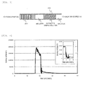
- FIG. 3 is a schematic diagram inside the sample loop 206 after the sample injection operation.
- the flow path switching valve 207 switches the flow path from Load to Inject, and the extracted sample solution is sent to the ionization source 114 by the operation of the passing pump 202.
- Each component in the extracted sample solution is ionized in the ionization source 114, and sent to the mass spectrometry section 115.
- the mass spectrometry section 115 the ionized components are separated for detection according to mass-to-charge (m/z).
- FIG. 4 represents the time dependent changes in the signal intensity detected in the mass spectrometry section 115 according to the present embodiment.
- the horizontal axis represents the time after the switching of the flow path to Inject by the flow path switching valve 207
- the vertical axis represents the signal intensity of the ionized tacrolimus.
- a 70% methanol aqueous solution containing 10 mmol/L of ammonium acetate was used as the flowing solvent 201.
- the passing pump 202 had a flow rate of 100 ⁇ L/min, and the sample loop 206 had a 60 ⁇ L volume.
- the sample injection operation injected the first air layer (5 ⁇ L), the extracted sample solution (injected in 10 ⁇ L), the second air layer (15 ⁇ L), and the washing solution 203 (2-propanol, 30 ⁇ L) into the sample loop 206.
- the tacrolimus contained in the extracted sample solution was detected in the mass spectrometry section 115 after about 16 seconds from the switching of the flow path by the flow path switching valve 207, and the signal intensity increased almost vertically.
- the signal intensity showed a rapid decrease after about 21 seconds from the switching of the flow path, and the count reached zero.
- Another signal was immediately detected, and the signal became gradually weaker over the course of about 10 seconds until it was finally undetectable after about 35 seconds from the switching of the flow path.
- the signal detected in the 6 second period from 16 seconds to 21 seconds after the switching of the flow path is attributed to the extracted sample solution between the two air layers.
- the signal detected after 22 seconds from the switching of the flow path is due to the extracted sample solution that remained in the sample loop 206, the ionization source 114, and the pipe, and washed by the washing solution 203.
- the rapid increase or decrease of signal intensity is due to two air layers disposed on the both sides of the extracted sample solution, preventing the extracted sample solution from being mixed and diluted with the flowing solvent 201 or the washing solution 203. While the air layer is passing the ionization source 114, the extracted sample solution does not exist in the ionization source 114, and accordingly the signal intensity count was zero.
- a quantitative analysis of components from mass spectrometry signals typically uses the integration value of the signal intensity, specifically the peak area.
- a further reduction of the measurement time can be achieved by using the 0 count time of signal intensity as the reference point of a peak area in the waveform of the signal intensity obtained in the present embodiment.
- the time needed to wash the flow path can be reduced by increasing the flow rate of the passing pump 202 and the velocity of the flowing solvent 201 at the time when the signal intensity has decreased to the zero count.
- Changing the flow rate of the passing pump 202 changes the ionization efficiency in the ionization source 114, and the signal intensity obtained in the mass spectrometry section 115 fluctuates.
- this does not affect the result of quantification because the peak area calculations only use the signal intensity from the zero count signal intensity (air layer) to the signal intensity that has decreased to 0 count.
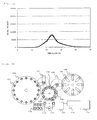
- FIG. 5 represents a conventional sample injection method performed under the same measurement conditions as in the present embodiment except for the absence of the two air layers.
- FIG. 5 represents the time dependent signal intensity changes when the extracted sample solution is passed to the ionization source 114 in contact with the flowing solvent 201 and the washing solution 203.
- the signal intensity gradually increased after about 10 seconds from the switching of the flow path, and became the maximum after about 24 seconds before the signal became undetectable after about 45 seconds.
- the signal intensity obtained in the result presented in FIG. 4 of the present embodiment was at least two times as strong as that shown in FIG. 5 , and the signal intensity of the component became undetectable about 10 seconds earlier.
- FIGS. 6 and 7 Another embodiment of the present invention is described below with reference to FIGS. 6 and 7 .
- FIG. 6 shows an automatic analyzer that is intended to automatically and continuously analyze trace components contained in biofluids such as serum and urine, and that includes a solid phase extracting mechanism for performing solid phase extraction as a pretreatment, a sample injection device for passing an extracted sample solution, and a MS equipped with an ESI ionization source. More specifically, Fig. 6 represents an example of an analysis of the immunosuppressant tacrolimus contained in a whole blood sample.
- the difference from First Embodiment is the configuration of a sample injection section 301, and the other configuration is the same as in First Embodiment.
- FIG. 7 is a detailed diagram of the sample injection section 301.
- the sample injection section 301 is configured from a passing pump 202 that delivers a flowing solvent 201; a syringe pump 204 that draws the extracted sample solution in the extract container 110, and the washing solution 203; a needle 205 that is placed in the extracted sample solution and the washing solution 203 when drawing these solutions; a sample loop 206 that retains the drawn extracted sample solution; a flow path switching valve 207 that connects the passing pump 202, the syringe pump 204, the needle 205, and the both ends of the sample loop 206 to the ionization source 114, and is adapted to switch the flow path to pass the retained extracted sample solution in the sample loop 206 to the ionization source 114; a waste receptacle 208 that collects the liquid ejected from the needle 205; a washing pump 303 that delivers the washing solution 302; and a three-way joint 304 that connects the flow path between the passing pump 202
- the operation of the sample injection section 301 is described below.
- the sample injection section 301 is in a standby state until the sample injection section 113 receives the extract container 110 containing the extracted sample solution, and the passing pump 202 passes the flowing solvent 201 to the ionization source 114 at a predetermined flow rate.
- the washing pump 303 remains inactivated with the washing solution 302 filling the flow path to the three-way joint 304.
- the flow path switching valve 207 switches the flow path to Inject, and the flowing solvent 201 is passed to the ionization source 114 through the sample loop 206.
- the syringe pump 204 repeats the drawing and the ejection of the washing solution 203 into the waste receptacle 208 to fill the flow path between the syringe pump 204 and the needle 205 with the liquid and remove the air.
- the sample injection operation is started upon the extract container 110 being sent to the sample injection section 301 in a standby state.
- the flow path switching valve 207 switches the flow path from Inject (solid line in FIG. 7 ) to Load (dotted line in FIG. 7 ). This connects the syringe pump 204 and the needle 205 with the sample loop 206 in between.
- the needle 205 is then moved to above the extract container where there is no liquid, and the syringe pump 204 performs a certain draw operation to draw air into the needle 205 through the needle tip (first air layer).
- the needle 205 is lifted down to move the tip into the extracted sample solution, and the syringe pump 204 performs a certain draw operation to draw the extracted sample solution into the needle 205 through the needle tip.
- the needle 205 is then lifted up to move the tip out of the extracted sample solution, and the syringe pump 204 performs a certain draw operation to draw air into the needle 205 through the needle tip (second air layer).
- the tip of the needle 205 is then moved into the washing solution 203, and the syringe pump 204 performs a certain draw operation. This draws air into the needle 205 through the needle tip, and, at the same time, injects the extracted sample solution between the two air layers into the sample loop 206.
- the flow path switching valve 207 switches the flow path from Load to Inject, and the extracted sample solution is sent to the ionization source 114 by the operation of the passing pump 202.
- Each component in the extracted sample solution is ionized in the ionization source 114, and sent to the mass spectrometry section 115.
- the mass spectrometry section 115 the ionized components are separated for detection according to mass-to-charge (m/z).
- the extracted sample solution is sent to the ionization source 114 by being sandwiched between the two air layers. Accordingly, as shown in FIG. 4 , the signal intensity rapidly increases upon the transition from the air layer to the extracted sample solution in the ionization source, and rapidly decreases upon the transition from the extracted sample solution to the air layer after a certain time period.
- the rapid signal intensity decrease is determined by signal processing, and washing of the flow path is started. Specifically, the washing pump 303 is operated to pass the washing solution 302.
- the washing solution 302 reaches the ionization source 114 through the flow path switching valve 207 and the sample loop 206.
- the washing solution 302 uses a solvent with a strong dissolving power for the contaminating components and the drugs contained in the whole blood in the extracted sample solution.
- the primary contaminating component of the whole blood is the lipid.
- an organic solvent such as 2-propanol and acetone may be used for the washing solution 302.
- the flow rate can be increased in the flow path from the three-way joint 304.
- This increases the velocity of the washing solution 302, and the washing time can be reduced as in First Embodiment in which the flow rate of the passing pump 202 is increased to increase the velocity of the washing solution.
- injecting a mixture of the washing solution 302 and the flowing solvent 201 into the ionization source 114 changes the ionization efficiency in the ionization source 114, and the signal intensity obtained in the mass spectrometry section 115 fluctuates.
- this does not affect the result of quantification because the peak area calculations only use the signal intensity from the zero count signal intensity (air layer) to the signal intensity that has decreased to 0 count.
- the three-way joint 304 is installed between the passing pump 202 and the flow path switching valve 207.
- the three-way joint 304 may be installed between the flow path switching valve 207 and the ionization source 114 to further reduce the washing time, provided that it is certain that the residual contaminating components or drugs occur in the ionization source 114.
Landscapes
- Chemical & Material Sciences (AREA)
- Analytical Chemistry (AREA)
- General Health & Medical Sciences (AREA)
- Health & Medical Sciences (AREA)
- Life Sciences & Earth Sciences (AREA)
- Biochemistry (AREA)
- Physics & Mathematics (AREA)
- General Physics & Mathematics (AREA)
- Immunology (AREA)
- Pathology (AREA)
- Automatic Analysis And Handling Materials Therefor (AREA)
- Other Investigation Or Analysis Of Materials By Electrical Means (AREA)
- Sampling And Sample Adjustment (AREA)
Applications Claiming Priority (2)
| Application Number | Priority Date | Filing Date | Title |
|---|---|---|---|
| JP2012276356A JP6035603B2 (ja) | 2012-12-19 | 2012-12-19 | 試料導入装置 |
| PCT/JP2013/078407 WO2014097731A1 (ja) | 2012-12-19 | 2013-10-21 | 試料導入装置 |
Publications (2)
| Publication Number | Publication Date |
|---|---|
| EP2937687A1 true EP2937687A1 (de) | 2015-10-28 |
| EP2937687A4 EP2937687A4 (de) | 2016-10-05 |
Family
ID=50978079
Family Applications (1)
| Application Number | Title | Priority Date | Filing Date |
|---|---|---|---|
| EP13865867.9A Withdrawn EP2937687A4 (de) | 2012-12-19 | 2013-10-21 | Probeninjektor |
Country Status (5)
| Country | Link |
|---|---|
| US (2) | US20150308986A1 (de) |
| EP (1) | EP2937687A4 (de) |
| JP (1) | JP6035603B2 (de) |
| CN (1) | CN104870993B (de) |
| WO (1) | WO2014097731A1 (de) |
Cited By (1)
| Publication number | Priority date | Publication date | Assignee | Title |
|---|---|---|---|---|
| WO2019199825A1 (en) * | 2018-04-10 | 2019-10-17 | Wiederin Daniel R | System for collecting liquid samples and transporting over distances while maintaining a liquid sample segment |
Families Citing this family (16)
| Publication number | Priority date | Publication date | Assignee | Title |
|---|---|---|---|---|
| GB0724736D0 (en) | 2007-12-19 | 2008-01-30 | Oxford Nanolabs Ltd | Formation of layers of amphiphilic molecules |
| WO2016006609A1 (ja) * | 2014-07-08 | 2016-01-14 | 国立研究開発法人産業技術総合研究所 | 採水装置兼粘性係数測定装置および粘性係数測定方法 |
| CN104730216B (zh) * | 2015-04-16 | 2016-12-07 | 肖巍 | 一种分析计量装置及液体分析系统 |
| US10241013B2 (en) * | 2015-12-08 | 2019-03-26 | Elemental Scientific, Inc. | Inline dilution and autocalibration for ICP-MS speciation analysis |
| KR101795747B1 (ko) * | 2016-01-15 | 2017-11-08 | 고려대학교 산학협력단 | 비연속적 시료 분획 및 통합유닛과 이를 구비한 이중 온라인 다기능 액체크로마토그래피 장치 |
| US10955390B2 (en) | 2017-09-01 | 2021-03-23 | Shimadzu Corporation | Autosampler and liquid chromatograph |
| JP2019074371A (ja) * | 2017-10-13 | 2019-05-16 | 株式会社島津製作所 | 質量分析装置を用いた特定物質監視システム |
| JP6864609B2 (ja) * | 2017-11-27 | 2021-04-28 | 株式会社日立製作所 | 光学分析装置、物質の製造システム、物質の製造方法、及びプログラム |
| EP3522201B1 (de) * | 2018-02-02 | 2020-10-07 | Tofwerk AG | Autosampler |
| CN109115579A (zh) * | 2018-10-16 | 2019-01-01 | 湖北工业大学 | 一种高通量样品前处理平台及加液方法 |
| CN111979087B (zh) * | 2019-05-22 | 2023-08-15 | 湖南乐准智芯生物科技有限公司 | 一种pcr微反应室芯片及其进样方法 |
| WO2021158674A1 (en) * | 2020-02-03 | 2021-08-12 | Elemental Scientific, Inc. | Inline chemical agent addition for inline reaction with fluid sample for analytic determinations |
| WO2021241357A1 (ja) * | 2020-05-29 | 2021-12-02 | 株式会社日立ハイテク | 自動分析装置の制御方法 |
| JP7571156B2 (ja) * | 2020-12-16 | 2024-10-22 | 株式会社日立ハイテク | オートサンプラの流路洗浄方法及びオートサンプラの流路洗浄装置 |
| CN113640364A (zh) * | 2021-07-21 | 2021-11-12 | 长江存储科技有限责任公司 | 一种传输方法和装置 |
| CN116869819A (zh) * | 2023-05-18 | 2023-10-13 | 太仓艺斯高医疗器械科技有限公司 | 用于脂质纳米颗粒合成、透析的一体化系统及方法 |
Family Cites Families (20)
| Publication number | Priority date | Publication date | Assignee | Title |
|---|---|---|---|---|
| US3504799A (en) * | 1968-04-02 | 1970-04-07 | Beckman Instruments Inc | Sample injector |
| US3918913A (en) * | 1974-12-02 | 1975-11-11 | Lilly Co Eli | Sampler-injector for liquid chromatography |
| US4311484A (en) * | 1980-04-09 | 1982-01-19 | Cortex Research Corporation | Specimen sampling apparatus |
| CN1009765B (zh) * | 1983-12-29 | 1990-09-26 | 株式会社岛津制作所 | 自动进料方法 |
| JPS6250659A (ja) | 1985-08-29 | 1987-03-05 | Shimadzu Corp | 液体クロマトグラフへの試料導入方法 |
| JPS62138753A (ja) * | 1985-12-12 | 1987-06-22 | Hitachi Ltd | 液体クロマトグラフイによる分画・分取方法および装置 |
| US4957009A (en) * | 1988-09-23 | 1990-09-18 | Spectra-Physics, Inc. | Pushloop liquid sampling method |
| JP2573678B2 (ja) * | 1988-11-14 | 1997-01-22 | 日本分光株式会社 | 液体クロマトグラフ用試料注入方法 |
| US5134445A (en) * | 1989-02-14 | 1992-07-28 | Canon Kabushiki Kaisha | Sample inspecting method and apparatus |
| US5468643A (en) * | 1991-08-28 | 1995-11-21 | The United States Of America As Represented By The Department Of Health And Human Services | Switching valve system for direct biological sample injection for LC analysis |
| JPH07311187A (ja) * | 1994-05-13 | 1995-11-28 | Shiseido Co Ltd | 液体クロマトグラフィ装置における試料注入方法及び注入装置 |
| JPH07159415A (ja) | 1993-12-08 | 1995-06-23 | Hitachi Ltd | 自動試料導入方法 |
| EP0686848A1 (de) | 1994-05-09 | 1995-12-13 | Shiseido Company Limited | Flüssigchromatograph mit Mikro- oder Halbmikrokolonne |
| US6136195A (en) * | 1998-04-10 | 2000-10-24 | Transgenomic, Inc. | MIPC column cleaning system and process |
| DE19926163B4 (de) * | 1998-06-19 | 2008-07-03 | Shimadzu Corp. | Flüssigchromatograph |
| JP2004283083A (ja) * | 2003-03-24 | 2004-10-14 | Hitachi Ltd | オンライン化学反応装置、及び解析システム |
| JP4522432B2 (ja) * | 2006-05-17 | 2010-08-11 | エーエムアール株式会社 | サンプルインジェクション用ニードルユニットおよびそれを用いたシリンジのサンプル吸引、洗浄装置 |
| JP2010014559A (ja) * | 2008-07-04 | 2010-01-21 | Shimadzu Corp | 分取液体クロマトグラフ装置 |
| AU2008243144A1 (en) * | 2008-11-06 | 2010-05-20 | Quark Technologies Australia Pty Ltd | Improvements in Radiopharmaceutical Purification |
| WO2010119801A1 (ja) * | 2009-04-16 | 2010-10-21 | 株式会社島津製作所 | 液体クロマトグラフ |
-
2012
- 2012-12-19 JP JP2012276356A patent/JP6035603B2/ja not_active Expired - Fee Related
-
2013
- 2013-10-21 EP EP13865867.9A patent/EP2937687A4/de not_active Withdrawn
- 2013-10-21 US US14/651,247 patent/US20150308986A1/en not_active Abandoned
- 2013-10-21 CN CN201380066520.6A patent/CN104870993B/zh not_active Expired - Fee Related
- 2013-10-21 WO PCT/JP2013/078407 patent/WO2014097731A1/ja not_active Ceased
-
2017
- 2017-10-12 US US15/730,936 patent/US10794874B2/en not_active Expired - Fee Related
Cited By (4)
| Publication number | Priority date | Publication date | Assignee | Title |
|---|---|---|---|---|
| WO2019199825A1 (en) * | 2018-04-10 | 2019-10-17 | Wiederin Daniel R | System for collecting liquid samples and transporting over distances while maintaining a liquid sample segment |
| US11499895B2 (en) | 2018-04-10 | 2022-11-15 | Elemental Scientific, Inc. | System for collecting liquid samples and transporting over distances while maintaining a liquid sample segment |
| US11761860B2 (en) | 2018-04-10 | 2023-09-19 | Elemental Scientific, Inc. | System for collecting liquid samples and transporting over distances while maintaining a liquid sample segment |
| TWI859135B (zh) * | 2018-04-10 | 2024-10-21 | 美商自然科學公司 | 用於傳輸樣品之系統及方法 |
Also Published As
| Publication number | Publication date |
|---|---|
| JP2014119400A (ja) | 2014-06-30 |
| CN104870993A (zh) | 2015-08-26 |
| US20180038837A1 (en) | 2018-02-08 |
| JP6035603B2 (ja) | 2016-11-30 |
| EP2937687A4 (de) | 2016-10-05 |
| US20150308986A1 (en) | 2015-10-29 |
| US10794874B2 (en) | 2020-10-06 |
| WO2014097731A1 (ja) | 2014-06-26 |
| CN104870993B (zh) | 2017-09-22 |
Similar Documents
| Publication | Publication Date | Title |
|---|---|---|
| US10794874B2 (en) | Sample injection device | |
| EP3896440B1 (de) | Flüssigchromatograf-massenspektrometer | |
| US9470664B2 (en) | Chromatographic interface | |
| US10942096B2 (en) | Automated system for remote inline concentration of ultra-low concentrations in pure chemicals | |
| US12368038B2 (en) | Automated system for remote inline concentration and homogenization of ultra-low concentrations in pure chemicals | |
| US20080142444A1 (en) | Liquid chromatograph apparatus | |
| US10643830B2 (en) | Specific substance monitoring system using mass spectrometer | |
| JP5707264B2 (ja) | 試料導入装置 | |
| EP3236256A1 (de) | Flüssigchromatograph | |
| KR20250042131A (ko) | 순수 화학물질 내의 초-저 농축물의 원격 인라인 농축을 위한 자동화된 시스템 | |
| US12130267B2 (en) | Analyzing method for azo compound | |
| CN104833761A (zh) | 一种快速分析样品中的糖类化合物的方法 | |
| CN103293268B (zh) | 一种人尿氢化可的松的检测方法 | |
| JP5202272B2 (ja) | 液体クロマトグラフ、液体クロマトグラフ用送液ポンプおよび液体クロマトグラフの洗浄方法 | |
| CN106979985B (zh) | 液相色谱原子光谱联用系统 | |
| EP4006952B1 (de) | Anomaliedetektion von gasflussparametern in der massenspektrometrie | |
| Rainville et al. | Increasing bioanalytical assay sensitivity for low exposure compounds with Xevo TQ-S | |
| GB2519395A (en) | Chromatographic interface | |
| Muller et al. | LC Coupled to MS–a User Report | |
| JPH09257779A (ja) | 微量陰イオン分析方法及び微量陰イオン分析装置 | |
| He et al. | A high-throughput, ultrafast, and online three-phase electro-extraction method for analysis of trace level basic pharmaceuticals |
Legal Events
| Date | Code | Title | Description |
|---|---|---|---|
| PUAI | Public reference made under article 153(3) epc to a published international application that has entered the european phase |
Free format text: ORIGINAL CODE: 0009012 |
|
| 17P | Request for examination filed |
Effective date: 20150715 |
|
| AK | Designated contracting states |
Kind code of ref document: A1 Designated state(s): AL AT BE BG CH CY CZ DE DK EE ES FI FR GB GR HR HU IE IS IT LI LT LU LV MC MK MT NL NO PL PT RO RS SE SI SK SM TR |
|
| AX | Request for extension of the european patent |
Extension state: BA ME |
|
| DAX | Request for extension of the european patent (deleted) | ||
| A4 | Supplementary search report drawn up and despatched |
Effective date: 20160902 |
|
| RIC1 | Information provided on ipc code assigned before grant |
Ipc: G01N 27/62 20060101AFI20160829BHEP Ipc: G01N 30/26 20060101ALI20160829BHEP Ipc: G01N 30/24 20060101ALI20160829BHEP Ipc: G01N 35/08 20060101ALI20160829BHEP Ipc: G01N 30/06 20060101ALI20160829BHEP Ipc: G01N 30/60 20060101ALI20160829BHEP Ipc: G01N 30/20 20060101ALI20160829BHEP Ipc: G01N 30/32 20060101ALI20160829BHEP |
|
| STAA | Information on the status of an ep patent application or granted ep patent |
Free format text: STATUS: EXAMINATION IS IN PROGRESS |
|
| RAP1 | Party data changed (applicant data changed or rights of an application transferred) |
Owner name: HITACHI HIGH-TECH CORPORATION |
|
| 17Q | First examination report despatched |
Effective date: 20200612 |
|
| STAA | Information on the status of an ep patent application or granted ep patent |
Free format text: STATUS: THE APPLICATION HAS BEEN WITHDRAWN |
|
| 18W | Application withdrawn |
Effective date: 20201021 |