EP2939511A1 - Säherz und Einzelkornsämaschine - Google Patents
Säherz und Einzelkornsämaschine Download PDFInfo
- Publication number
- EP2939511A1 EP2939511A1 EP14166850.9A EP14166850A EP2939511A1 EP 2939511 A1 EP2939511 A1 EP 2939511A1 EP 14166850 A EP14166850 A EP 14166850A EP 2939511 A1 EP2939511 A1 EP 2939511A1
- Authority
- EP
- European Patent Office
- Prior art keywords
- seed
- shaft
- säherz
- agitator shaft
- seeder
- Prior art date
- Legal status (The legal status is an assumption and is not a legal conclusion. Google has not performed a legal analysis and makes no representation as to the accuracy of the status listed.)
- Granted
Links
Images



Classifications
-
- A—HUMAN NECESSITIES
- A01—AGRICULTURE; FORESTRY; ANIMAL HUSBANDRY; HUNTING; TRAPPING; FISHING
- A01C—PLANTING; SOWING; FERTILISING
- A01C7/00—Sowing
- A01C7/04—Single-grain seeders with or without suction devices
- A01C7/042—Single-grain seeders with or without suction devices using pneumatic means
- A01C7/044—Pneumatic seed wheels
- A01C7/046—Pneumatic seed wheels with perforated seeding discs
-
- A—HUMAN NECESSITIES
- A01—AGRICULTURE; FORESTRY; ANIMAL HUSBANDRY; HUNTING; TRAPPING; FISHING
- A01C—PLANTING; SOWING; FERTILISING
- A01C7/00—Sowing
- A01C7/20—Parts of seeders for conducting and depositing seed
-
- A—HUMAN NECESSITIES
- A01—AGRICULTURE; FORESTRY; ANIMAL HUSBANDRY; HUNTING; TRAPPING; FISHING
- A01C—PLANTING; SOWING; FERTILISING
- A01C7/00—Sowing
- A01C7/20—Parts of seeders for conducting and depositing seed
- A01C7/201—Mounting of the seeding tools
- A01C7/205—Mounting of the seeding tools comprising pressure regulation means
Definitions
- the invention relates to a presety of diseases and conditions in which a presety of diseases and conditions in which a presety of diseases and conditions in which a presety of diseases and conditions in which a presety of diseases and conditions in which a presety of diseases and conditions in which a presety of diseases and conditions in which a presety of diseases and conditions in which a presety of diseases and conditions in which a presety of diseases and a seeder according to claim 7.
- Seed hearts for precision seed drills are used for the defined spreading of seeds, whereby the seed usually has no defined dimensions.
- seed hearts should be used as universally as possible for a variety of seed species of different sizes and geometric shapes. Since seed is partly very expensive, as little seed as possible should be produced and if possible no seeds should be destroyed.
- the application at a defined distance and in each case of a single seed grain plays an important role, so that the plants can develop optimally until harvest.
- Object of the present invention is therefore to provide a sheherz, which is versatile and reliable, so works as trouble-free as possible over a long period of time.
- the basic idea of the present invention is to arrange a stirrer shaft in a receiving section for receiving the seed on the seed disc or in the region of an inlet of the seed into the seed heart and to form the stirrer shaft in a modular exchangeable manner.
- Modular interchangeable means in particular that the seed must not be dismantled to replace the stirrer shaft.
- Seed hearts are usually constructed in two parts and have a variety of attachments, which must be used consuming in a disassembly and subsequent assembly.
- Modular interchangeable means, in particular, that the sowing heart does not have to be removed from the precision seed drill to replace the stirrer shaft. This is particularly advantageous because a seeder usually has a variety of sheherzen, namely at least one seed per shenism.
- stirrer shafts can be used for different seeds, which in particular have different outer contours, preferably different stirrer knobs on the circumference.
- the agitator shaft can be plugged onto a drive shaft, in particular with a drive of the seed disc, preferably via a bevel gear mechanism.
- a drive shaft in particular with a drive of the seed disc, preferably via a bevel gear mechanism.
- the drive shaft rotatably with a double ball bearing in a, in particular in a half of the poleherzes molded, hollow cylinder.
- the agitator shaft can be mounted at least predominantly, in particular exclusively, at its drive-side end, so that the modular exchange, in particular from the opposite end of the agitator shaft, is simplified.
- the drive shaft in particular has only one degree of freedom in the direction of rotation, preferably by positive engagement in the hollow cylinder.
- the agitator shaft is exchangeable through a, preferably opposite to the hollow cylinder, the housing opening of the seed ore.
- the stirring shaft in particular by a linear Aufsteckterrorism, in a simple manner interchangeable.
- the agitator shaft has a head which is shaped congruently to an inner wall of a housing opening, in particular a circular-cylindrical one. Due to the congruence of shape of the head of the seed having receiving portion of sheherzes can be closed.
- the head is arranged flush with an inner wall of the seed ore on a shoulder directed toward the drive side of the stirring shaft, in particular in the region of the receiving section.
- the head has a play relative to the inner wall of the housing opening, and is in particular rotatable with respect to this.
- the game is preferably such that no seed is trapped between the inner wall of the housing opening and the head.
- the actuating elements comprise at least one arranged in a receiving portion for receiving the seed on the sowing disc agitator shaft for moving the seed.
- a speed of the stirring shaft can be increased.
- an axis of the agitator shaft extends in the radial direction to the seed disc and parallel to a flat side of the seed disc.
- a stirring section of the stirring shaft is arranged in a storage region of the seed ore, preferably in the region of an inlet of the seed.
- the actuating elements comprise, alternatively or in addition to the adjustable scraper and / or the stirring shaft, a blower motor for generating negative pressure at the scoop holes.
- a blower motor for generating negative pressure at the scoop holes.
- the blower motor can be controlled by the control of the blower motor applied to the Söchöchern negative pressure for receiving the seed at the Söchöchern. If an underlay is detected by an evaluation unit, the negative pressure is increased and in the case of overcrowding the negative pressure is reduced, in particular in the range of a negative pressure range (corridor), preferably based on the respective seed.
- a combination of the adjustable scraper, the agitator shaft and the control of the fan motor is preferably provided, so that in particular control priorities can be defined and / or a control sequence in the case of under-occupancy and / or over-occupancy of individual sumps, preferably in each case separately, can be defined , preferably depending on the particular seed.
- the present invention relates to a seeder with one or more above-described stirrer shafts.
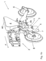
- FIGS. 1a and 1b a sowing unit 1 of a precision seed drill according to the invention is shown, which is attached via an arm 2 on the frame of the precision seed drill. Accordingly, the direction of travel when operating the seeder in the direction indicated by the arrow F direction.
- a setup 3 On the arm 2, which allows a pivoting movement, preferably as a vertical movement by forming the arm 2 as a parallelogram, are a setherz 3, a arranged above the workingherzes 3 tank 4, a arranged below the sheherzes 3 clutch 5 and two in the direction of travel before F and behind the sheherz 3 arranged, with respect to the sheherz 3 swivel wheels 6 attached.
- the tank 4 is over a Lid 4d closable and filled with seed, which in turn is guided laterally into the sheherz 3 via a channel 4k.
- the seed is singled in sheherz 3 and placed over the coulter 5 in a by a share tip 7 of the coulter 5 open furrow in the soil soil.
- the sheherz 3 consists of a first half 3.1 and a second half 3.2, which define a working space 8 therein.
- the working space 8 is divided by a seed disc 9 in a pressure side and a seed side.
- 9 seeding holes 15 are distributed on the circumference of the seeding disc (seedhole circle) through which the pressure side and the seed side are connected. Otherwise, the pressure side and the seed side are sealed off from each other by the seed disc 9 and in particular by corresponding seals.
- the seed from the tank 4 arrives at the seed disc 9 via a feed 30 in a receiving section 31 for receiving the seed.
- a negative pressure which is generated by a negative pressure region of the first half 3.1.
- a fan motor Connected to the negative pressure area is a fan motor, which can be controlled by a saw core control device.
- the seeding holes 15 have suitable diameters which are in particular in the range from 0.5 mm to 3 mm.
- each sowing hole 15 picks up a single seed grain, which does not always work 100% in practice, in particular because of the different severity of the seeds of each seed.
- a seed hole 15 no seed or even picking up multiple seeds. This leads to the corresponding sowing point in the field soil, which either no plant originates or for example two plants, which are not sufficiently supplied with nutrients and therefore remain underdeveloped.
- An agitating shaft 18, 18 'having stirring knobs 19, 19' for enhancing the movement of the seed in the receiving section 31 is preferably arranged in the region of the inlet 30 and / or on the beginning of the receiving section 31 in the direction of rotation R.
- the region of the inlet 30 is provided in particular with a fill level monitoring (not shown) in order to counteract a strong conveying effect of the agitator shaft 18, 18 '. If the filling level monitoring gives a corresponding signal that there is no or too little seed in the region of the inlet 30, the rotational speed of the agitator shaft 18, 18 'is reduced or the rotation of the agitator shaft 18, 18' is stopped.
- a scraper (not shown) for stripping excess seed from the sockets 15 is preferably disposed in the direction of rotation R between the agitator shaft 18, 18 'and a seed heart monitor (not shown), in particular closer to the agitator shaft 18, 18' than to the seed heart monitor.
- FIG. 2a It can be seen that according to the invention stirrer shafts 18, 18 'of different types in the sheherz 3 are used.
- the execution of the lower agitator shaft 18 has at its periphery 33 stirring knobs 19, which in the form and dimensions of stirring knobs 19 'of in FIG. 2a Distinguish above stirring shaft 18 '.
- the four on the circumference 33 of the Stirring shaft 18 'arranged stirring knobs 19' have a wing shape.
- the stirring shafts 18, 18 ' are preferably identical.
- both agitator shafts 18, 18 ' have a worm 26 on a drive-side end.
- the worm 26 ensures upon rotation of the agitator shaft 18, 18 'for a promotion of the seed in the direction of Rhaknoppen 19, 19'.
- the agitator shaft 18, 18 ' is at least partially, preferably predominantly, formed as a hollow body with a receiving opening 27 for receiving a drive shaft 12.
- the agitator shaft 18, 18 ' is axially aufsteckbar with its receiving opening 27 on the drive shaft 12 and has only one degree of freedom in the insertion direction.
- the stirring shaft 18, 18 ' is thus rotatably connected to the drive shaft 12.
- the stirring shaft 18, 18 At a surrounding the receiving opening 27 stop side 28, the stirring shaft 18, 18 'abuts against a stop ring 32 of a hollow cylinder for receiving a double ball bearing 13 of the drive shaft 12, in particular sealingly. This prevents that seed from the receiving portion 31 enters a drive space of a drive 10 for driving the seed disc 9.
- the drive shaft 12 extends in particular radially parallel to the seed disc 9 and / or orthogonal to a drive shaft of the drive 10 of the seeding disc 9.
- the drive shaft 12 is coupled in particular via a bevel gear 11 to the drive 10 so that during operation of the seed disc 9 so during rotation of scale 9, also the stirring shaft 18, 18 'rotates.
- a separate drive for, in particular separately controllable and / or controllable drive of the drive shaft 12 is provided.
- this has a head 20 with a circular cylindrical circumference, which is formed congruent to a housing opening 16 of the poleherzes 3.
- the head 20 has, in particular, a play relative to an inner wall 17 of the housing opening 16, so that the agitator shaft 18, 18 'can be removed through the housing opening 16 in an insertion direction extending axially with respect to the drive shaft 12.
- the housing opening 16 is closed by a lid 22, in particular sealing.
- the cover 22 fixes the agitator shaft 18, 18 'on the drive shaft 12 by means of at least one, in particular annular, projection 29.
- the projection 29 is in the mounted state at one, in particular tangential to the seed disc 9 and / or radially to the drive shaft 12 extending end face 25th the stirring shaft 18, 18 'on.
- the cover 22 thus simultaneously stabilizes the rotational movement of the free end of the agitator shaft 18, 18 '.
- the lid 22 also has a viewing window 23, which closes a viewing opening 24 of the sheherzes 3. Through the viewing opening 24 and the viewing window 23 gives insight into the operation of the sheherzes 3 inside the sheherzes. 3
Landscapes
- Life Sciences & Earth Sciences (AREA)
- Soil Sciences (AREA)
- Environmental Sciences (AREA)
- Sowing (AREA)
- Pretreatment Of Seeds And Plants (AREA)
Abstract
Description
- Die Erfindung betrifft ein Säherz gemäß Patentanspruch 1 und eine Einzelkornsämaschine gemäß Patentanspruch 7.
- Säherzen für Einzelkornsämaschinen dienen zur definierten Ausbringung von Saatgut, wobei das Saatgut In der Regel keine definierten Abmessungen aufweist. Darüber hinaus sollen Säherzen möglichst universell für eine Vielzahl von Saatgutarten unterschiedlicher Größe und geometrischer Form einsetzbar sein. Da Saatgut teils sehr teuer ist, soll möglichst wenig Saatgutausschuss produziert werden und möglichst kein Saatgut zerstört werden. Eine große Rolle spielt auch die Ausbringung in einem definierten Abstand und jeweils eines einzelnen Saatgutkorns, damit die Pflanzen sich bis zur Ernte optimal entwickeln können.
- Bei der zuverlässigen Vereinzelung des Saatguts auf Sälöchern einer rotierenden Säscheibe kommt es außerdem darauf an, dass ein langfristiger und störungsfreier Einsatz gewährleistet ist. Probleme bereiten nicht nur die oben genannten unterschiedlichen Abmessungen, sondern auch Staub und etwaige Verschmutzungen oder Fremdkörper, die bei gattungsgemäßen Säherzen häufig für Funktionsstörungen verantwortlich zeichnen, insbesondere bei längerem Betrieb.
- Aufgabe der vorliegenden Erfindung ist es daher, ein Säherz anzugeben, das vielseitig einsetzbar ist und zuverlässig, also möglichst störungsfrei über einen möglichst langen Zeitraum arbeitet.
- Diese Aufgabe wird mit den Merkmalen der Patentansprüche 1 und 7 gelöst. Vorteilhafte Weiterbildungen der Erfindung sind in den Unteransprüchen angegeben. In den Rahmen der Erfindung fallen sämtliche Kombinationen aus zumindest zwei in der Beschreibung, den Ansprüchen und/oder den Figuren angegebenen Merkmalen. Soweit Wertebereiche angegeben sind, sollen auch etwaige Zwischenwerte als Grenzwerte mit offenbart gelten.
- Grundidee der vorliegenden Erfindung ist es, eine Rührwelle in einem Aufnahmeabschnitt zur Aufnahme des Saatguts an der Säscheibe beziehungsweise im Bereich eines Zulaufs des Saatguts in das Säherz anzuordnen und die Rührwelle modular austauschbar auszubilden. Modular austauschbar heißt insbesondere, dass das Säherz nicht demontiert werden muss, um die Rührwelle auszutauschen. Säherzen sind meist zweiteilig aufgebaut und weisen eine Vielzahl von Anbauten auf, die bei einer Demontage und anschließender Montage aufwendig eingesetzt werden müssen. Modular austauschbar heißt insbesondere, dass das Säherz zum Auswechseln der Rührwelle nicht aus der Einzelkornsämaschine ausgebaut werden muss. Dies ist insbesondere deshalb von Vorteil, weil eine Einzelkornsämaschine meist eine Vielzahl von Säherzen aufweist, nämlich mindestens je ein Säherz pro Säreihe.
- Durch den modularen Aufbau ist es erfindungsgemäß möglich, die Rührwelle bei Verschleiß einfach auszutauschen, ohne eine Aufwendige Demontage des Säherzes von der Einzelkornsämaschine und/oder eine Zerlegung des Säherzes durchführen zu müssen. Außerdem können für unterschiedliche Saatgüter verschiedene Rührwellen eingesetzt werden, die insbesondere verschiedene Außenkonturen, vorzugsweise verschiedene Rührnoppen am Umfang, aufweisen.
- Gemäß einer bevorzugten Ausführungsform der Erfindung ist vorgesehen, dass die Rührwelle auf eine, insbesondere mit einem Antrieb der Säscheibe, vorzugsweise über ein Kegelradgetriebe, gekoppelte, Antriebswelle aufsteckbar ist. Durch die Kopplung mit der Antriebswelle wird der bauliche Aufwand für das Säherz verringert, da auf einen eigenen Antrieb für die Rührwelle verzichtet werden kann.
- In Weiterbildung ist es erfindungsgemäß denkbar, die Antriebswelle mit einem Doppelkugellager in einem, insbesondere in einer Gehäusehälfte des Säherzes eingeformten, Hohlzylinder drehbar anzuordnen. Auf diese Weise kann die Rührwelle zumindest überwiegend, insbesondere ausschließlich, an ihrem antriebsseitigen Ende gelagert werden, sodass der modulare Austausch, insbesondere von dem gegenüberliegenden Ende der Rührwelle her, vereinfacht wird.
- Die Antriebswelle besitzt insbesondere ausschließlich einen Freiheitsgrad in Rotationsrichtung, vorzugsweise durch formschlüssigen Einsatz in den Hohlzylinder.
- Gemäß einer weiteren vorteilhaften Ausführungsform der vorliegenden Erfindung ist vorgesehen, dass die Rührwelle durch eine, insbesondere gegenüberliegend zum Hohlzylinder angeordnete, Gehäuseöffnung des Säherzes austauschbar ist. Auf diese Weise ist die Rührwelle, insbesondere durch eine lineare Aufsteckbewegung, auf einfache Art und Weise austauschbar.
- Mit Vorteil ist die Rührwelle gemäß einer weiteren Ausführungsform der Erfindung mittels eines, insbesondere die Gehäuseöffnung, vorzugsweise dichtend, verschließenden, Deckels drehbar fixierbar. Hierdurch wird ein einfacher Austausch ermöglicht, wobei der Deckel insbesondere gleichzeitig mehrere Funktionen erfüllen kann, nämlich:
- a) Verschließen der Gehäuseöffnung, insbesondere dichtend gegenüber der Umgebung und/oder
- b) Halterung der Rührwelle in einer Steckrichtung der Rührwelle beziehungsweise in Axialrichtung der Antriebswelle und/oder
- c) Führung einer Stirnseite eines Kopfes der Rührwelle und dadurch Stabilisierung des, insbesondere freien, Endes der Rührwelle, das von der Antriebsseite entfernt ist.
- Gemäß einem weiteren Erfindungsaspekt weist die Rührwelle einen formkongruent zu einer Innenwand einer Gehäuseöffnung ausgestalteten, insbesondere kreiszylinderförmigen, Kopf auf. Durch die Formkongruenz des Kopfes kann der das Saatgut aufweisende Aufnahmeabschnitt des Säherzes verschlossen werden. Der Kopf ist insbesondere an einer zur Antriebsseite der Rührwelle gerichteten Schulter bündig zu einer Innenwand des Säherzes angeordnet, insbesondere im Bereich des Aufnahmeabschnitts. Der Kopf weist insbesondere ein Spiel gegenüber der Innenwand der Gehäuseöffnung auf, und ist insbesondere gegenüber dieser rotierbar. Das Spiel ist vorzugsweise so bemessen, dass kein Saatgut zwischen der Innenwand der Gehäuseöffnung und dem Kopf eingeklemmt wird.
- Hierdurch wird die Montage der Rührwelle auf einfache Art und Weise ermöglicht, bei gleichzeitig zuverlässigem Betrieb der Rührwelle über einen langen Zeitraum.
- Alternativ oder zusätzlich zu einem verstellbaren Abstreifer als Betätigungselement zur Beeinflussung einer Belegung der Sälöcher ist es erfindungsgemäß in einer Ausführungsform denkbar, dass die Betätigungselemente mindestens eine in einem Aufnahmeabschnitt zur Aufnahme des Saatguts an der Säscheibe angeordnete Rührwelle zur Bewegung des Saatguts umfassen. Eine zusätzlich zu der natürlichen Bewegung des Saatguts entlang der Säscheibe erfolgende, insbesondere quer dazu verlaufende Bewegung des Saatguts führt zu einer besseren Belegung der Sälöcher, insbesondere bei einer Unterbelegung. In diesem Fall kann insbesondere eine Drehzahl der Rührwelle vergrößert werden. Insbesondere verläuft eine Achse der Rührwelle in Radialrichtung zur Säscheibe und parallel zu einer Flachseite der Säscheibe. Insbesondere ist ein Rührabschnitt der Rührwelle in einem Vorratsbereich des Säherzes, vorzugsweise im Bereich eines Zulaufs des Saatguts, angeordnet.
- In einer weiteren, vorteilhaften Ausführungsform umfassen die Betätigungselemente alternativ oder zusätzlich zu dem verstellbaren Abstreifer und/oder der Rührwelle einen Gebläsemotor zur Erzeugung von Unterdruck an den Sälöchern. Erfindungsgemäß kann durch die Steuerung des Gebläsemotors der an den Sälöchern anliegende Unterdruck zur Aufnahme des Saatguts an den Sälöchern gesteuert werden. Wird von einer Auswerteeinheit eine Unterbelegung festgestellt, wird der Unterdruck erhöht und im Falle einer Überbelegung wird der Unterdruck reduziert, insbesondere im Bereich eines, vorzugsweise bezogen auf das jeweilige Saatgut, festgelegten Unterdruckbereiches (Korridor).
- Erfindungsgemäß bevorzugt wird eine Kombination aus dem verstellbaren Abstreifer, der Rührwelle und der Ansteuerung des Gebläsemotors vorgesehen, so dass insbesondere Steuerungsprioritäten festlegbar sind und/oder eine Steuerungssequenz im Falle einer Unterbelegung und/oder einer Überbelegung einzelner Sälöcher, vorzugsweise jeweils separat, festlegbar ist/sind, vorzugsweise abhängig vom jeweiligen Saatgut.
- Weiterhin betrifft die vorliegende Erfindung eine Einzelkornsämaschine mit einer oder mehreren vorbeschriebenen Rührwellen.
- Weitere Vorteile, Merkmale und Einzelheiten der Erfindung ergeben sich aus der nachfolgenden Beschreibung bevorzugter Ausführungsbeispiele sowie anhand der Zeichnungen. Diese zeigen in:
- Figur 1a und 1b
- perspektivische Ansichten einer Ausführungsform eines Einzelkornsäaggregats einer gattungsgemäßen Einzelkornsämaschine mit einem Säherz in Fahrtrichtung von schräg hinten (
Figur 1a ) und von schräg vorne (Figur 1b ), - Figur 2a
- eine perspektivische Ansicht des Säherzes der Ausführungsform gemäß
Figur 1 mit einem Ausbruch zur Darstellung einer Rührwelle und einer teilweise dargestellten Säscheibe mit Sälöchern, - Figur 2b
- eine Seitenansicht des Säherzes gemäß
Figur 2a mit geöffnetem Säherz und - Figur 2c
- eine geschnittene Aufsicht des Säherzes gemäß
Figur 2a . - In den Figuren sind gleiche Bauteile und Bauteile mit der gleichen Funktion mit den gleichen Bezugszeichen gekennzeichnet.
- In den
Figuren 1a und1b ist ein Säaggregat 1 einer erfindungsgemäßen Einzelkornsämaschine dargestellt, das über einen Arm 2 am Rahmen der Einzelkornsämaschine befestigt ist. Dementsprechend ist die Fahrtrichtung bei Betrieb der Einzelkornsämaschine in der durch den Pfeil F angegebenen Richtung. - An dem Arm 2, der eine Schwenkbewegung, vorzugsweise als Vertikalbewegung durch Ausbildung des Arms 2 als Parallelogrammarm, zulässt, sind ein Säherz 3, ein oberhalb des Säherzes 3 angeordneter Tank 4, ein unterhalb des Säherzes 3 angeordnetes Säschar 5 sowie zwei in Fahrtrichtung F vor und hinter dem Säherz 3 angeordnete, gegenüber dem Säherz 3 schwenkbare Laufräder 6 angebracht. Der Tank 4 ist über einen Deckel 4d verschließbar und mit Saatgut befüllbar, das wiederum über einen Kanal 4k seitlich in das Säherz 3 geführt wird.
- Das Saatgut wird im Säherz 3 vereinzelt und über das Säschar 5 in eine durch eine Scharspitze 7 des Säschars 5 geöffnete Furche im Ackerboden abgelegt.
- Das Säherz 3 besteht aus einer ersten Hälfte 3.1 und einer zweiten Hälfte 3.2, die ein Säherzgehäuse und einen darin befindlichen Arbeitsraum 8 definieren. Der Arbeitsraum 8 wird durch eine Säscheibe 9 in eine Druckseite und eine Saatgutseite unterteilt.
- Konzentrisch zur kreisförmigen Säscheibe 9 sind am Umfang der Säscheibe 9 Sälöcher 15 verteilt (Sälochkreis), durch welche die Druckseite und die Saatgutseite verbunden sind. Ansonsten sind die Druckseite und die Saatgutseite durch die Säscheibe 9 und insbesondere durch entsprechende Dichtungen voneinander abgedichtet.
- In der Hälfte 3.2 kommt das Saatgut von dem Tank 4 über einen Zulauf 30 in einem Aufnahmeabschnitt 31 zur Aufnahme des Saatguts an der Säscheibe 9 an. Zumindest im Aufnahmeabschnitt 31 liegt an den Sälöchern 15 ein Unterdruck an, der durch einen Unterdruckbereich der ersten Hälfte 3.1 erzeugt wird. An den Unterdruckbereich ist ein Gebläsemotor angeschlossen, der von einer Säherzsteuerungseinrichtung steuerbar ist.
- Die Sälöcher 15 weisen je nach zu vereinzelndem Saatgut geeignete Durchmesser auf, die insbesondere im Bereich von 0,5 mm bis 3 mm liegen.
- Idealerweise nimmt jedes Säloch 15 ein einziges Saatkorn auf, was insbesondere wegen der unterschiedlichen Ausprägung der Saatkörner jedes Saatguts in der Praxis nicht immer zu 100 % funktioniert. Je nach verwendetem Saatgut und abhängig von der Einstellung des Säherzes 3 und der Fahrgeschwindigkeit kommt es vor, dass ein Säloch 15 kein Saatkorn oder sogar mehrere Saatkörner aufnimmt. Dies führt an der entsprechenden Sästelle im Ackerboden dazu, das entweder keine Pflanze entsteht oder zum Beispiel zwei Pflanzen, die nicht ausreichend mit Nährstoffen versorgt werden und daher unterentwickelt bleiben.
- Besonders kritisch ist es jedoch, wenn einzelne Säaggregate einer Einzelkornsämaschine vollständig ausfallen, beispielsweise durch eine Funktionsstörung oder hohen Verschmutzungsgrad.
- Eine Rührnoppen 19, 19' aufweisende Rührwelle 18, 18' zur Verstärkung der Bewegung des Saatguts im Aufnahmeabschnitt 31 ist bevorzugt im Bereich des Zulaufs 30 und/oder am in Rotationsrichtung R liegenden Beginn des Aufnahmeabschnitts 31 angeordnet.
- Der Bereich des Zulaufs 30 ist insbesondere mit einer Füllstandsüberwachung (nicht dargestellt) versehen, um einer zu starken Förderwirkung der Rührwelle 18, 18' entgegen zu wirken. Wenn die Füllstandsüberwachung ein entsprechendes Signal gibt, dass sich im Bereich des Zulaufs 30 kein oder zu wenig Saatgut befindet, wird die Drehzahl der Rührwelle 18, 18' reduziert oder die Rotation der Rührwelle 18, 18' gestoppt.
- Ein Abstreifer (nicht dargestellt) zum Abstreifen überschüssigen Saatguts von den Sälöchern 15 ist in Rotationsrichtung R vorzugsweise zwischen der Rührwelle 18, 18' und einer Säherzüberwachungseinrichtung (nicht dargestellt) angeordnet, insbesondere näher an der Rührwelle 18, 18' als an der Säherzüberwachungseinrichtung.
-
Figur 2a ist zu entnehmen, dass erfindungsgemäß Rührwellen 18, 18' verschiedener Ausführungen in das Säherz 3 einsetzbar sind. Die Ausführung der unteren Rührwelle 18 weist an ihrem Umfang 33 Rührnoppen 19 auf, die sich in Form und Abmessungen von Rührnoppen 19' der inFigur 2a oben dargestellten Rührwelle 18' unterscheiden. Die vier am Umfang 33 der Rührwelle 18' angeordneten Rührnoppen 19' weisen eine Flügelform auf. Abgesehen von der Zahl, Form und Größe der Rührnoppen 19, 19' und/oder des Durchmessers des die Rührnoppen 19, 19' an seinem Umfang aufweisenden Hohlkörpers sind die Rührwellen 18, 18' bevorzugt identisch. - So weisen beide Rührwellen 18, 18' in einer optionalen Ausführung an einem antriebsseitigen Ende eine Schnecke 26 auf. Die Schnecke 26 sorgt bei Rotation der Rührwelle 18, 18' für eine Förderung des Saatguts in Richtung der Rührnoppen 19, 19'. Die Rührnoppen 19, 19' sorgen für eine Durchwirbelung des Saatguts im Aufnahmeabschnitt 31.
- Die Rührwelle 18, 18' ist zumindest teilweise, vorzugsweise überwiegend, als Hohlkörper mit einer Aufnahmeöffnung 27 zur Aufnahme einer Antriebswelle 12 ausgebildet. Die Rührwelle 18, 18' ist mit ihrer Aufnahmeöffnung 27 auf die Antriebswelle 12 axial aufsteckbar und weist lediglich in Steckrichtung einen Freiheitsgrad auf. Die Rührwelle 18, 18' ist somit drehfest mit der Antriebswelle 12 verbunden.
- An einer die Aufnahmeöffnung 27 umgebenden Anschlagsseite 28 schlägt die Rührwelle 18, 18' an einen Anschlagring 32 eines Hohlzylinders zur Aufnahme eines Doppelkugellagers 13 der Antriebswelle 12, insbesondere dichtend, an. Hierdurch wird verhindert, dass Saatgut von dem Aufnahmeabschnitt 31 in einen Antriebsraum eines Antriebs 10 zum Antrieb der Säscheibe 9 gelangt.
- Die Antriebswelle 12 verläuft insbesondere radial parallel zur Säscheibe 9 und/oder orthogonal zu einer Antriebswelle des Antriebs 10 der Säscheibe 9. Die Antriebswelle 12 ist insbesondere über ein Kegelradgetriebe 11 mit dem Antrieb 10 gekoppelt, sodass sich beim Betrieb der Säscheibe 9 also bei Rotation der Säscheibe 9, auch die Rührwelle 18, 18' dreht.
- Alternativ ist ein eigener Antrieb zum, insbesondere separat steuer- und/oder regelbaren Antrieb der Antriebswelle 12 vorgesehen.
- Am freien Ende der Rührwelle 18, 18' weist diese einen Kopf 20 mit kreiszylinderförmigen Umfang auf, der kongruent zu einer Gehäuseöffnung 16 des Säherzes 3 geformt ist. Der Kopf 20 weist insbesondere ein Spiel gegenüber einer Innenwand 17 der Gehäuseöffnung 16 auf, sodass die Rührwelle 18, 18' durch die Gehäuseöffnung 16 in einer axial zur Antriebswelle 12 verlaufenden Steckrichtung entnommen werden kann.
- Die Gehäuseöffnung 16 ist mit einem Deckel 22, insbesondere dichtend, verschließbar. Der Deckel 22 fixiert die Rührwelle 18, 18' auf der Antriebswelle 12 mittels mindestens einem, insbesondere ringförmigem, Vorsprung 29. Der Vorsprung 29 liegt in montiertem Zustand an einer, insbesondere tangential zur Säscheibe 9 und/oder radial zur Antriebswelle 12 verlaufenden, Stirnseite 25 der Rührwelle 18, 18' an. Der Deckel 22 stabilisiert somit gleichzeitig die Rotationsbewegung des freien Endes der Rührwelle 18, 18'.
- Der Deckel 22 weist weiterhin ein Sichtfenster 23 auf, das eine Sichtöffnung 24 des Säherzes 3 verschließt. Durch die Sichtöffnung 24 und das Sichtfenster 23 erhält man Einblick in den Betrieb des Säherzes 3 im Inneren des Säherzes 3.
-
- 1
- Säaggregat
- 2
- Arm
- 3
- Säherz
- 3.1
- Hälfte
- 3.2
- Hälfte
- 4
- Tank
- 4d
- Deckel
- 4k
- Kanal
- 5
- Säschar
- 6
- Laufräder
- 7
- Scharspitze
- 8
- Arbeitsraum
- 9
- Säscheibe
- 10
- Antrieb
- 11
- Kegelradgetriebe
- 12
- Antriebswelle
- 13
- Doppelkugellager
- 14
- Hohlzylinder
- 15
- Sälöcher
- 16
- Gehäuseöffnung
- 17
- Innenwand
- 18, 18'
- Rührwelle
- 19, 19'
- Rührnoppen
- 20
- Kopf
- 21
- Stirnseite
- 22
- Deckel
- 23
- Sichtfenster
- 24
- Sichtöffnung
- 25
- Stirnseite
- 26
- Schnecke
- 27
- Aufnahmeöffnung
- 28
- Anschlagseite
- 29
- Vorsprung
- 30
- Zulauf
- 31
- Aufnahmeabschnitt
- 32
- Anschlagring
- 33
- Umfang
- R
- Rotationsrichtung
- F
- Fahrtrichtung
Claims (7)
- Säherz für eine Einzelkornsämaschine mit- einer in einer Rotationsrichtung (R) rotierbaren Säscheibe (9) mit einer Vielzahl von konzentrisch zur Säscheibe (9) entlang mindestens eines Sälochkreises verteilten Sälöchern (15) und- mindestens einer in einem Aufnahmeabschnitt (31) zur Aufnahme des Saatguts an den Sälöchern (15) der Säscheibe (9) angeordnete Rührwelle (18, 18') zur Bewegung des Saatguts,dadurch gekennzeichnet, dass die Rührwelle (18, 18') modular austauschbar ausgebildet ist.
- Säherz nach Anspruch 1, bei der die Rührwelle (18, 18') auf eine, insbesondere mit einem Antrieb (10) der Säscheibe (9), vorzugsweise über ein Kegelradgetriebe (11), gekoppelten, Antriebswelle (12) aufsteckbar ist.
- Säherz nach Anspruch 2, bei der die Antriebswelle (12) mit einem Doppelkugellager (13) in einem, insbesondere in einer Gehäusehälfte (3.2) des Säherzes (3) eingeformten, Hohlzylinder (14) drehbar geführt ist.
- Säherz nach einem der vorhergehenden Ansprüche, bei der die Rührwelle (18, 18') durch eine, insbesondere gegenüberliegend zum Hohlzylinder (14) angeordnete, Gehäuseöffnung (16) des Säherzes (3) austauschbar ist.
- Säherz nach einem der vorhergehenden Ansprüche, bei der die Rührwelle (18, 18') mittels eines, insbesondere die Gehäuseöffnung (16), vorzugsweise dichtend, verschließenden, Deckels (22) drehbar fixierbar ist.
- Säherz nach einem der vorhergehenden Ansprüche, bei der die Rührwelle (18, 18') einen formkongruent zu einer Innenwand (17) einer Gehäuseöffnung (16) ausgestalteten, insbesondere kreiszylinderförmigen, Kopf (20) aufweist.
- Einzelkornsämaschine mit einem Säherz (3) nach einem der vorhergehenden Ansprüche.
Priority Applications (10)
| Application Number | Priority Date | Filing Date | Title |
|---|---|---|---|
| DK14166850.9T DK2939511T3 (en) | 2014-05-02 | 2014-05-02 | Sow-heart and single-grain drill. |
| PL14166850T PL2939511T3 (pl) | 2014-05-02 | 2014-05-02 | Dozownik siewnika i siewnik punktowy |
| EP14166850.9A EP2939511B1 (de) | 2014-05-02 | 2014-05-02 | Säherz und Einzelkornsämaschine |
| ES14166850.9T ES2598962T3 (es) | 2014-05-02 | 2014-05-02 | Unidad dosificadora y máquina sembradora de grano individual |
| HUE14166850A HUE029148T2 (hu) | 2014-05-02 | 2014-05-02 | Vetõszív szemenkénti vetõgéphez |
| PCT/EP2015/051846 WO2015165598A1 (de) | 2014-05-02 | 2015-01-29 | Säherz und einzelkornsämaschine |
| CA2933012A CA2933012C (en) | 2014-05-02 | 2015-01-29 | Seeding heart for a single-grain seeding machine |
| US15/035,650 US9901022B2 (en) | 2014-05-02 | 2015-01-29 | Seeding heart with a modular agitator shaft for seed |
| CN201580003185.4A CN105828597B (zh) | 2014-05-02 | 2015-01-29 | 用于播种机的播种机芯 |
| BR112016011967-3A BR112016011967B1 (pt) | 2014-05-02 | 2015-01-29 | núcleo de semeadura e máquina de semeadura de grão único |
Applications Claiming Priority (1)
| Application Number | Priority Date | Filing Date | Title |
|---|---|---|---|
| EP14166850.9A EP2939511B1 (de) | 2014-05-02 | 2014-05-02 | Säherz und Einzelkornsämaschine |
Publications (2)
| Publication Number | Publication Date |
|---|---|
| EP2939511A1 true EP2939511A1 (de) | 2015-11-04 |
| EP2939511B1 EP2939511B1 (de) | 2016-07-20 |
Family
ID=50630663
Family Applications (1)
| Application Number | Title | Priority Date | Filing Date |
|---|---|---|---|
| EP14166850.9A Active EP2939511B1 (de) | 2014-05-02 | 2014-05-02 | Säherz und Einzelkornsämaschine |
Country Status (10)
| Country | Link |
|---|---|
| US (1) | US9901022B2 (de) |
| EP (1) | EP2939511B1 (de) |
| CN (1) | CN105828597B (de) |
| BR (1) | BR112016011967B1 (de) |
| CA (1) | CA2933012C (de) |
| DK (1) | DK2939511T3 (de) |
| ES (1) | ES2598962T3 (de) |
| HU (1) | HUE029148T2 (de) |
| PL (1) | PL2939511T3 (de) |
| WO (1) | WO2015165598A1 (de) |
Cited By (1)
| Publication number | Priority date | Publication date | Assignee | Title |
|---|---|---|---|---|
| CN110972628A (zh) * | 2020-01-13 | 2020-04-10 | 鄂尔多斯市悍龙园林科技有限公司 | 一种手推式单粒玉米穴播机 |
Families Citing this family (3)
| Publication number | Priority date | Publication date | Assignee | Title |
|---|---|---|---|---|
| CN108055902A (zh) * | 2018-01-26 | 2018-05-22 | 河北农业大学 | 一种用于农业机械中的小麦排种器的清种片 |
| PL4305942T3 (pl) | 2022-07-12 | 2025-05-19 | Kverneland Group Soest Gmbh | Aparat wysiewający z wałkiem mieszadła do siewnika |
| US12317771B2 (en) | 2022-09-19 | 2025-06-03 | Cnh Industrial Canada, Ltd. | Agitator drive system for a product metering system |
Citations (2)
| Publication number | Priority date | Publication date | Assignee | Title |
|---|---|---|---|---|
| EP0046709A1 (de) * | 1980-08-21 | 1982-03-03 | Nodet-Gougis | Verteilvorrichtung für pneumatische Einzelkornsämaschine |
| EP0145237A1 (de) * | 1983-11-18 | 1985-06-19 | Stanhay Webb Limited | Samenausgabemechanismus |
Family Cites Families (8)
| Publication number | Priority date | Publication date | Assignee | Title |
|---|---|---|---|---|
| GB1591794A (en) * | 1976-10-28 | 1981-06-24 | Rota Spoon Ltd | Seed dispensing device |
| US4793511A (en) * | 1984-03-26 | 1988-12-27 | Deere & Company | Seed meter having seed disk aperture cleaning wiper and brush arrangement |
| CN2070086U (zh) * | 1990-08-04 | 1991-01-30 | 唐永生 | 人力小麦滚压旋窝窝播机 |
| US5784985A (en) * | 1996-03-04 | 1998-07-28 | Deere & Company | Mechanical seed meter |
| US6352042B1 (en) * | 2000-10-10 | 2002-03-05 | Deere & Company | Internal seed knockout assembly |
| RU2241323C1 (ru) * | 2003-06-09 | 2004-12-10 | Азово-Черноморская государственная агроинженерная академия | Пневматический высевающий аппарат |
| JP4389120B2 (ja) * | 2004-09-13 | 2009-12-24 | 井関農機株式会社 | 苗植機等の車輪 |
| FR2971391B1 (fr) * | 2011-02-10 | 2014-02-21 | Kuhn Sa | Boitier de distribution pour semoir monograine avec pales d'agitation et semoir utilisant un tel boitier |
-
2014
- 2014-05-02 PL PL14166850T patent/PL2939511T3/pl unknown
- 2014-05-02 HU HUE14166850A patent/HUE029148T2/hu unknown
- 2014-05-02 EP EP14166850.9A patent/EP2939511B1/de active Active
- 2014-05-02 DK DK14166850.9T patent/DK2939511T3/en active
- 2014-05-02 ES ES14166850.9T patent/ES2598962T3/es active Active
-
2015
- 2015-01-29 WO PCT/EP2015/051846 patent/WO2015165598A1/de not_active Ceased
- 2015-01-29 CN CN201580003185.4A patent/CN105828597B/zh not_active Expired - Fee Related
- 2015-01-29 CA CA2933012A patent/CA2933012C/en active Active
- 2015-01-29 US US15/035,650 patent/US9901022B2/en active Active
- 2015-01-29 BR BR112016011967-3A patent/BR112016011967B1/pt not_active IP Right Cessation
Patent Citations (2)
| Publication number | Priority date | Publication date | Assignee | Title |
|---|---|---|---|---|
| EP0046709A1 (de) * | 1980-08-21 | 1982-03-03 | Nodet-Gougis | Verteilvorrichtung für pneumatische Einzelkornsämaschine |
| EP0145237A1 (de) * | 1983-11-18 | 1985-06-19 | Stanhay Webb Limited | Samenausgabemechanismus |
Cited By (2)
| Publication number | Priority date | Publication date | Assignee | Title |
|---|---|---|---|---|
| CN110972628A (zh) * | 2020-01-13 | 2020-04-10 | 鄂尔多斯市悍龙园林科技有限公司 | 一种手推式单粒玉米穴播机 |
| CN110972628B (zh) * | 2020-01-13 | 2024-04-26 | 鄂尔多斯市悍龙园林科技有限公司 | 一种手推式单粒玉米穴播机 |
Also Published As
| Publication number | Publication date |
|---|---|
| US9901022B2 (en) | 2018-02-27 |
| HUE029148T2 (hu) | 2017-02-28 |
| ES2598962T3 (es) | 2017-01-30 |
| EP2939511B1 (de) | 2016-07-20 |
| CN105828597B (zh) | 2019-05-17 |
| CA2933012C (en) | 2020-06-09 |
| CA2933012A1 (en) | 2015-11-05 |
| CN105828597A (zh) | 2016-08-03 |
| PL2939511T3 (pl) | 2017-01-31 |
| DK2939511T3 (en) | 2016-10-24 |
| WO2015165598A1 (de) | 2015-11-05 |
| US20160270287A1 (en) | 2016-09-22 |
| BR112016011967B1 (pt) | 2020-07-07 |
| BR112016011967A2 (pt) | 2018-02-06 |
Similar Documents
| Publication | Publication Date | Title |
|---|---|---|
| EP2807914B1 (de) | Säherzsteuerungseinrichtung, Säherz und Einzelkornsämaschine | |
| EP0195900B1 (de) | Säaggregat für Einzelkornsämaschinen | |
| DE2217513A1 (de) | Verteilervorrichtung an Sämaschinen | |
| EP2939511B1 (de) | Säherz und Einzelkornsämaschine | |
| EP3592128B1 (de) | Verteilmaschine | |
| EP3323717B1 (de) | Rotormast | |
| DE102020002763A1 (de) | Dosiervorrichtung für eine landwirtschaftliche Maschine | |
| EP2989877B1 (de) | Dosieraggregat für körniges gut | |
| EP2923544B1 (de) | Pneumatische einzelkornsämaschine | |
| DE2259450A1 (de) | Vorrichtung zum ablegen von koernigem saatgut im erdreich, vorzugsweise in verbindung mit einzelkornsaemaschinen | |
| DE102008056534A1 (de) | Säherz und Einzelkornsämaschine | |
| EP2923543A1 (de) | Pneumatische einzelkornsämaschine | |
| EP2974583B9 (de) | Säherz und Einzelkornsämaschine | |
| EP2946904A1 (de) | Vorrichtung und Verfahren zur Entgasung von aufzubereitendem Material | |
| DE10224325A1 (de) | Bodenbearbeitungsgerät | |
| EP2503929A1 (de) | Küchengerät mit verarbeitungsbehälter | |
| EP1679448B1 (de) | Vorrichtung zum Bearbeiten von Schüttgütern | |
| EP3292747A1 (de) | Sämaschine mit vereinzelungsvorrichtung | |
| DE102015217701A1 (de) | Säscheibe eines Einzelkorndosiergeräts | |
| EP3011818B1 (de) | Verteilmaschine mit einem streugutbehälter, welcher mit einem rührwerk ausgestattet ist | |
| DE10319842B4 (de) | Entgasungseinrichtung für einen Extruder | |
| DE8713992U1 (de) | Einzelkornsämaschine | |
| EP1704762B1 (de) | Pneumatische Sämaschine | |
| EP3396163A1 (de) | Vakuumpumpe mit schmiermittelpegel-begrenzungsvorrichtung | |
| EP3542606B1 (de) | Kreiselegge und eingangsgetriebe für eine kreiselegge |
Legal Events
| Date | Code | Title | Description |
|---|---|---|---|
| PUAI | Public reference made under article 153(3) epc to a published international application that has entered the european phase |
Free format text: ORIGINAL CODE: 0009012 |
|
| 17P | Request for examination filed |
Effective date: 20150129 |
|
| AK | Designated contracting states |
Kind code of ref document: A1 Designated state(s): AL AT BE BG CH CY CZ DE DK EE ES FI FR GB GR HR HU IE IS IT LI LT LU LV MC MK MT NL NO PL PT RO RS SE SI SK SM TR |
|
| AX | Request for extension of the european patent |
Extension state: BA ME |
|
| GRAP | Despatch of communication of intention to grant a patent |
Free format text: ORIGINAL CODE: EPIDOSNIGR1 |
|
| INTG | Intention to grant announced |
Effective date: 20160314 |
|
| GRAS | Grant fee paid |
Free format text: ORIGINAL CODE: EPIDOSNIGR3 |
|
| GRAA | (expected) grant |
Free format text: ORIGINAL CODE: 0009210 |
|
| AK | Designated contracting states |
Kind code of ref document: B1 Designated state(s): AL AT BE BG CH CY CZ DE DK EE ES FI FR GB GR HR HU IE IS IT LI LT LU LV MC MK MT NL NO PL PT RO RS SE SI SK SM TR |
|
| REG | Reference to a national code |
Ref country code: GB Ref legal event code: FG4D Free format text: NOT ENGLISH |
|
| REG | Reference to a national code |
Ref country code: CH Ref legal event code: EP |
|
| REG | Reference to a national code |
Ref country code: IE Ref legal event code: FG4D Free format text: LANGUAGE OF EP DOCUMENT: GERMAN |
|
| REG | Reference to a national code |
Ref country code: AT Ref legal event code: REF Ref document number: 813195 Country of ref document: AT Kind code of ref document: T Effective date: 20160815 |
|
| REG | Reference to a national code |
Ref country code: DE Ref legal event code: R096 Ref document number: 502014001132 Country of ref document: DE |
|
| REG | Reference to a national code |
Ref country code: SE Ref legal event code: TRGR |
|
| REG | Reference to a national code |
Ref country code: RO Ref legal event code: EPE |
|
| REG | Reference to a national code |
Ref country code: NL Ref legal event code: FP |
|
| REG | Reference to a national code |
Ref country code: DK Ref legal event code: T3 Effective date: 20161020 |
|
| REG | Reference to a national code |
Ref country code: LT Ref legal event code: MG4D |
|
| REG | Reference to a national code |
Ref country code: ES Ref legal event code: FG2A Ref document number: 2598962 Country of ref document: ES Kind code of ref document: T3 Effective date: 20170130 |
|
| PG25 | Lapsed in a contracting state [announced via postgrant information from national office to epo] |
Ref country code: FI Free format text: LAPSE BECAUSE OF FAILURE TO SUBMIT A TRANSLATION OF THE DESCRIPTION OR TO PAY THE FEE WITHIN THE PRESCRIBED TIME-LIMIT Effective date: 20160720 Ref country code: RS Free format text: LAPSE BECAUSE OF FAILURE TO SUBMIT A TRANSLATION OF THE DESCRIPTION OR TO PAY THE FEE WITHIN THE PRESCRIBED TIME-LIMIT Effective date: 20160720 Ref country code: IS Free format text: LAPSE BECAUSE OF FAILURE TO SUBMIT A TRANSLATION OF THE DESCRIPTION OR TO PAY THE FEE WITHIN THE PRESCRIBED TIME-LIMIT Effective date: 20161120 Ref country code: NO Free format text: LAPSE BECAUSE OF FAILURE TO SUBMIT A TRANSLATION OF THE DESCRIPTION OR TO PAY THE FEE WITHIN THE PRESCRIBED TIME-LIMIT Effective date: 20161020 Ref country code: LT Free format text: LAPSE BECAUSE OF FAILURE TO SUBMIT A TRANSLATION OF THE DESCRIPTION OR TO PAY THE FEE WITHIN THE PRESCRIBED TIME-LIMIT Effective date: 20160720 Ref country code: HR Free format text: LAPSE BECAUSE OF FAILURE TO SUBMIT A TRANSLATION OF THE DESCRIPTION OR TO PAY THE FEE WITHIN THE PRESCRIBED TIME-LIMIT Effective date: 20160720 |
|
| REG | Reference to a national code |
Ref country code: SK Ref legal event code: T3 Ref document number: E 22264 Country of ref document: SK |
|
| PG25 | Lapsed in a contracting state [announced via postgrant information from national office to epo] |
Ref country code: LV Free format text: LAPSE BECAUSE OF FAILURE TO SUBMIT A TRANSLATION OF THE DESCRIPTION OR TO PAY THE FEE WITHIN THE PRESCRIBED TIME-LIMIT Effective date: 20160720 Ref country code: PT Free format text: LAPSE BECAUSE OF FAILURE TO SUBMIT A TRANSLATION OF THE DESCRIPTION OR TO PAY THE FEE WITHIN THE PRESCRIBED TIME-LIMIT Effective date: 20161121 Ref country code: GR Free format text: LAPSE BECAUSE OF FAILURE TO SUBMIT A TRANSLATION OF THE DESCRIPTION OR TO PAY THE FEE WITHIN THE PRESCRIBED TIME-LIMIT Effective date: 20161021 |
|
| REG | Reference to a national code |
Ref country code: HU Ref legal event code: AG4A Ref document number: E029148 Country of ref document: HU |
|
| REG | Reference to a national code |
Ref country code: DE Ref legal event code: R097 Ref document number: 502014001132 Country of ref document: DE |
|
| PG25 | Lapsed in a contracting state [announced via postgrant information from national office to epo] |
Ref country code: EE Free format text: LAPSE BECAUSE OF FAILURE TO SUBMIT A TRANSLATION OF THE DESCRIPTION OR TO PAY THE FEE WITHIN THE PRESCRIBED TIME-LIMIT Effective date: 20160720 |
|
| REG | Reference to a national code |
Ref country code: FR Ref legal event code: PLFP Year of fee payment: 4 |
|
| PLBE | No opposition filed within time limit |
Free format text: ORIGINAL CODE: 0009261 |
|
| STAA | Information on the status of an ep patent application or granted ep patent |
Free format text: STATUS: NO OPPOSITION FILED WITHIN TIME LIMIT |
|
| PG25 | Lapsed in a contracting state [announced via postgrant information from national office to epo] |
Ref country code: BG Free format text: LAPSE BECAUSE OF FAILURE TO SUBMIT A TRANSLATION OF THE DESCRIPTION OR TO PAY THE FEE WITHIN THE PRESCRIBED TIME-LIMIT Effective date: 20161020 Ref country code: SM Free format text: LAPSE BECAUSE OF FAILURE TO SUBMIT A TRANSLATION OF THE DESCRIPTION OR TO PAY THE FEE WITHIN THE PRESCRIBED TIME-LIMIT Effective date: 20160720 |
|
| 26N | No opposition filed |
Effective date: 20170421 |
|
| PG25 | Lapsed in a contracting state [announced via postgrant information from national office to epo] |
Ref country code: SI Free format text: LAPSE BECAUSE OF FAILURE TO SUBMIT A TRANSLATION OF THE DESCRIPTION OR TO PAY THE FEE WITHIN THE PRESCRIBED TIME-LIMIT Effective date: 20160720 Ref country code: LU Free format text: LAPSE BECAUSE OF NON-PAYMENT OF DUE FEES Effective date: 20170531 |
|
| REG | Reference to a national code |
Ref country code: CH Ref legal event code: PL |
|
| PG25 | Lapsed in a contracting state [announced via postgrant information from national office to epo] |
Ref country code: MC Free format text: LAPSE BECAUSE OF FAILURE TO SUBMIT A TRANSLATION OF THE DESCRIPTION OR TO PAY THE FEE WITHIN THE PRESCRIBED TIME-LIMIT Effective date: 20160720 |
|
| REG | Reference to a national code |
Ref country code: IE Ref legal event code: MM4A |
|
| PG25 | Lapsed in a contracting state [announced via postgrant information from national office to epo] |
Ref country code: CH Free format text: LAPSE BECAUSE OF NON-PAYMENT OF DUE FEES Effective date: 20170531 Ref country code: LI Free format text: LAPSE BECAUSE OF NON-PAYMENT OF DUE FEES Effective date: 20170531 |
|
| PG25 | Lapsed in a contracting state [announced via postgrant information from national office to epo] |
Ref country code: LU Free format text: LAPSE BECAUSE OF NON-PAYMENT OF DUE FEES Effective date: 20170502 |
|
| PG25 | Lapsed in a contracting state [announced via postgrant information from national office to epo] |
Ref country code: IE Free format text: LAPSE BECAUSE OF NON-PAYMENT OF DUE FEES Effective date: 20170502 |
|
| REG | Reference to a national code |
Ref country code: FR Ref legal event code: PLFP Year of fee payment: 5 |
|
| PG25 | Lapsed in a contracting state [announced via postgrant information from national office to epo] |
Ref country code: MT Free format text: LAPSE BECAUSE OF FAILURE TO SUBMIT A TRANSLATION OF THE DESCRIPTION OR TO PAY THE FEE WITHIN THE PRESCRIBED TIME-LIMIT Effective date: 20160720 |
|
| PG25 | Lapsed in a contracting state [announced via postgrant information from national office to epo] |
Ref country code: AL Free format text: LAPSE BECAUSE OF FAILURE TO SUBMIT A TRANSLATION OF THE DESCRIPTION OR TO PAY THE FEE WITHIN THE PRESCRIBED TIME-LIMIT Effective date: 20160720 |
|
| PG25 | Lapsed in a contracting state [announced via postgrant information from national office to epo] |
Ref country code: CY Free format text: LAPSE BECAUSE OF FAILURE TO SUBMIT A TRANSLATION OF THE DESCRIPTION OR TO PAY THE FEE WITHIN THE PRESCRIBED TIME-LIMIT Effective date: 20160720 |
|
| PG25 | Lapsed in a contracting state [announced via postgrant information from national office to epo] |
Ref country code: MK Free format text: LAPSE BECAUSE OF FAILURE TO SUBMIT A TRANSLATION OF THE DESCRIPTION OR TO PAY THE FEE WITHIN THE PRESCRIBED TIME-LIMIT Effective date: 20160720 |
|
| PG25 | Lapsed in a contracting state [announced via postgrant information from national office to epo] |
Ref country code: RO Free format text: LAPSE BECAUSE OF NON-PAYMENT OF DUE FEES Effective date: 20190502 |
|
| PG25 | Lapsed in a contracting state [announced via postgrant information from national office to epo] |
Ref country code: TR Free format text: LAPSE BECAUSE OF FAILURE TO SUBMIT A TRANSLATION OF THE DESCRIPTION OR TO PAY THE FEE WITHIN THE PRESCRIBED TIME-LIMIT Effective date: 20160720 |
|
| PGFP | Annual fee paid to national office [announced via postgrant information from national office to epo] |
Ref country code: NL Payment date: 20200527 Year of fee payment: 7 |
|
| PGFP | Annual fee paid to national office [announced via postgrant information from national office to epo] |
Ref country code: BE Payment date: 20200527 Year of fee payment: 7 |
|
| REG | Reference to a national code |
Ref country code: DE Ref legal event code: R082 Ref document number: 502014001132 Country of ref document: DE Representative=s name: KILBURN & STRODE LLP, NL Ref country code: DE Ref legal event code: R082 Ref document number: 502014001132 Country of ref document: DE Representative=s name: PATENTANWAELTE BECKER & MUELLER, DE |
|
| REG | Reference to a national code |
Ref country code: NL Ref legal event code: MM Effective date: 20210601 |
|
| REG | Reference to a national code |
Ref country code: BE Ref legal event code: MM Effective date: 20210531 |
|
| REG | Reference to a national code |
Ref country code: AT Ref legal event code: PC Ref document number: 813195 Country of ref document: AT Kind code of ref document: T Owner name: KVERNELAND GROUP SOEST GMBH, DE Effective date: 20220411 |
|
| REG | Reference to a national code |
Ref country code: HU Ref legal event code: GB9C Owner name: KVERNELAND GROUP SOEST GMBH, DE Free format text: FORMER OWNER(S): KVERNELAND AS, NO |
|
| REG | Reference to a national code |
Ref country code: ES Ref legal event code: PC2A Owner name: KVERNELAND GROUP SOEST GMBH Effective date: 20220525 |
|
| PG25 | Lapsed in a contracting state [announced via postgrant information from national office to epo] |
Ref country code: NL Free format text: LAPSE BECAUSE OF NON-PAYMENT OF DUE FEES Effective date: 20210601 |
|
| REG | Reference to a national code |
Ref country code: SK Ref legal event code: TE4A Ref document number: E 22264 Country of ref document: SK Owner name: KVERNELAND AS, 4353 KLEPP STASJON, NO Effective date: 20220704 Ref country code: SK Ref legal event code: PC4A Ref document number: E 22264 Country of ref document: SK Owner name: KVERNELAND GROUP SOEST GMBH, 59494 SOEST, DE Free format text: FORMER OWNER: KVERNELAND AS, 4353 KLEPP STASJON, NO Effective date: 20220704 |
|
| PG25 | Lapsed in a contracting state [announced via postgrant information from national office to epo] |
Ref country code: BE Free format text: LAPSE BECAUSE OF NON-PAYMENT OF DUE FEES Effective date: 20210531 |
|
| REG | Reference to a national code |
Ref country code: GB Ref legal event code: 732E Free format text: REGISTERED BETWEEN 20220707 AND 20220713 |
|
| REG | Reference to a national code |
Ref country code: DE Ref legal event code: R081 Ref document number: 502014001132 Country of ref document: DE Owner name: KVERNELAND GROUP SOEST GMBH, DE Free format text: FORMER OWNER: KVERNELAND AS, KVERNALAND, NO Ref country code: DE Ref legal event code: R082 Ref document number: 502014001132 Country of ref document: DE Representative=s name: PATENTANWAELTE BECKER & MUELLER, DE |
|
| REG | Reference to a national code |
Ref country code: DE Ref legal event code: R082 Ref document number: 502014001132 Country of ref document: DE |
|
| P01 | Opt-out of the competence of the unified patent court (upc) registered |
Effective date: 20230525 |
|
| PGFP | Annual fee paid to national office [announced via postgrant information from national office to epo] |
Ref country code: PL Payment date: 20250425 Year of fee payment: 12 Ref country code: DE Payment date: 20250521 Year of fee payment: 12 |
|
| PGFP | Annual fee paid to national office [announced via postgrant information from national office to epo] |
Ref country code: GB Payment date: 20250521 Year of fee payment: 12 Ref country code: ES Payment date: 20250627 Year of fee payment: 12 Ref country code: DK Payment date: 20250526 Year of fee payment: 12 |
|
| PGFP | Annual fee paid to national office [announced via postgrant information from national office to epo] |
Ref country code: HU Payment date: 20250523 Year of fee payment: 12 |
|
| PGFP | Annual fee paid to national office [announced via postgrant information from national office to epo] |
Ref country code: IT Payment date: 20250527 Year of fee payment: 12 |
|
| PGFP | Annual fee paid to national office [announced via postgrant information from national office to epo] |
Ref country code: FR Payment date: 20250528 Year of fee payment: 12 |
|
| PGFP | Annual fee paid to national office [announced via postgrant information from national office to epo] |
Ref country code: AT Payment date: 20250522 Year of fee payment: 12 |
|
| PGFP | Annual fee paid to national office [announced via postgrant information from national office to epo] |
Ref country code: SK Payment date: 20250428 Year of fee payment: 12 |
|
| PGFP | Annual fee paid to national office [announced via postgrant information from national office to epo] |
Ref country code: CZ Payment date: 20250425 Year of fee payment: 12 |
|
| PGFP | Annual fee paid to national office [announced via postgrant information from national office to epo] |
Ref country code: SE Payment date: 20250521 Year of fee payment: 12 |