EP2939862A2 - Personenfahrzeug mit einem modularen bedienfeld - Google Patents
Personenfahrzeug mit einem modularen bedienfeld Download PDFInfo
- Publication number
- EP2939862A2 EP2939862A2 EP15164980.3A EP15164980A EP2939862A2 EP 2939862 A2 EP2939862 A2 EP 2939862A2 EP 15164980 A EP15164980 A EP 15164980A EP 2939862 A2 EP2939862 A2 EP 2939862A2
- Authority
- EP
- European Patent Office
- Prior art keywords
- mount frame
- face plate
- control panel
- contact area
- contact sensor
- Prior art date
- Legal status (The legal status is an assumption and is not a legal conclusion. Google has not performed a legal analysis and makes no representation as to the accuracy of the status listed.)
- Granted
Links
Images




Classifications
-
- G—PHYSICS
- G06—COMPUTING OR CALCULATING; COUNTING
- G06F—ELECTRIC DIGITAL DATA PROCESSING
- G06F3/00—Input arrangements for transferring data to be processed into a form capable of being handled by the computer; Output arrangements for transferring data from processing unit to output unit, e.g. interface arrangements
- G06F3/01—Input arrangements or combined input and output arrangements for interaction between user and computer
- G06F3/03—Arrangements for converting the position or the displacement of a member into a coded form
- G06F3/041—Digitisers, e.g. for touch screens or touch pads, characterised by the transducing means
- G06F3/0412—Digitisers structurally integrated in a display
-
- B—PERFORMING OPERATIONS; TRANSPORTING
- B60—VEHICLES IN GENERAL
- B60K—ARRANGEMENT OR MOUNTING OF PROPULSION UNITS OR OF TRANSMISSIONS IN VEHICLES; ARRANGEMENT OR MOUNTING OF PLURAL DIVERSE PRIME-MOVERS IN VEHICLES; AUXILIARY DRIVES FOR VEHICLES; INSTRUMENTATION OR DASHBOARDS FOR VEHICLES; ARRANGEMENTS IN CONNECTION WITH COOLING, AIR INTAKE, GAS EXHAUST OR FUEL SUPPLY OF PROPULSION UNITS IN VEHICLES
- B60K35/00—Instruments specially adapted for vehicles; Arrangement of instruments in or on vehicles
- B60K35/10—Input arrangements, i.e. from user to vehicle, associated with vehicle functions or specially adapted therefor
-
- B—PERFORMING OPERATIONS; TRANSPORTING
- B60—VEHICLES IN GENERAL
- B60K—ARRANGEMENT OR MOUNTING OF PROPULSION UNITS OR OF TRANSMISSIONS IN VEHICLES; ARRANGEMENT OR MOUNTING OF PLURAL DIVERSE PRIME-MOVERS IN VEHICLES; AUXILIARY DRIVES FOR VEHICLES; INSTRUMENTATION OR DASHBOARDS FOR VEHICLES; ARRANGEMENTS IN CONNECTION WITH COOLING, AIR INTAKE, GAS EXHAUST OR FUEL SUPPLY OF PROPULSION UNITS IN VEHICLES
- B60K35/00—Instruments specially adapted for vehicles; Arrangement of instruments in or on vehicles
- B60K35/20—Output arrangements, i.e. from vehicle to user, associated with vehicle functions or specially adapted therefor
- B60K35/21—Output arrangements, i.e. from vehicle to user, associated with vehicle functions or specially adapted therefor using visual output, e.g. blinking lights or matrix displays
- B60K35/22—Display screens
-
- B—PERFORMING OPERATIONS; TRANSPORTING
- B60—VEHICLES IN GENERAL
- B60K—ARRANGEMENT OR MOUNTING OF PROPULSION UNITS OR OF TRANSMISSIONS IN VEHICLES; ARRANGEMENT OR MOUNTING OF PLURAL DIVERSE PRIME-MOVERS IN VEHICLES; AUXILIARY DRIVES FOR VEHICLES; INSTRUMENTATION OR DASHBOARDS FOR VEHICLES; ARRANGEMENTS IN CONNECTION WITH COOLING, AIR INTAKE, GAS EXHAUST OR FUEL SUPPLY OF PROPULSION UNITS IN VEHICLES
- B60K35/00—Instruments specially adapted for vehicles; Arrangement of instruments in or on vehicles
- B60K35/20—Output arrangements, i.e. from vehicle to user, associated with vehicle functions or specially adapted therefor
- B60K35/25—Output arrangements, i.e. from vehicle to user, associated with vehicle functions or specially adapted therefor using haptic output
-
- B—PERFORMING OPERATIONS; TRANSPORTING
- B60—VEHICLES IN GENERAL
- B60K—ARRANGEMENT OR MOUNTING OF PROPULSION UNITS OR OF TRANSMISSIONS IN VEHICLES; ARRANGEMENT OR MOUNTING OF PLURAL DIVERSE PRIME-MOVERS IN VEHICLES; AUXILIARY DRIVES FOR VEHICLES; INSTRUMENTATION OR DASHBOARDS FOR VEHICLES; ARRANGEMENTS IN CONNECTION WITH COOLING, AIR INTAKE, GAS EXHAUST OR FUEL SUPPLY OF PROPULSION UNITS IN VEHICLES
- B60K35/00—Instruments specially adapted for vehicles; Arrangement of instruments in or on vehicles
- B60K35/50—Instruments characterised by their means of attachment to or integration in the vehicle
-
- B—PERFORMING OPERATIONS; TRANSPORTING
- B60—VEHICLES IN GENERAL
- B60K—ARRANGEMENT OR MOUNTING OF PROPULSION UNITS OR OF TRANSMISSIONS IN VEHICLES; ARRANGEMENT OR MOUNTING OF PLURAL DIVERSE PRIME-MOVERS IN VEHICLES; AUXILIARY DRIVES FOR VEHICLES; INSTRUMENTATION OR DASHBOARDS FOR VEHICLES; ARRANGEMENTS IN CONNECTION WITH COOLING, AIR INTAKE, GAS EXHAUST OR FUEL SUPPLY OF PROPULSION UNITS IN VEHICLES
- B60K35/00—Instruments specially adapted for vehicles; Arrangement of instruments in or on vehicles
- B60K35/60—Instruments characterised by their location or relative disposition in or on vehicles
-
- G—PHYSICS
- G06—COMPUTING OR CALCULATING; COUNTING
- G06F—ELECTRIC DIGITAL DATA PROCESSING
- G06F1/00—Details not covered by groups G06F3/00 - G06F13/00 and G06F21/00
- G06F1/16—Constructional details or arrangements
-
- G—PHYSICS
- G06—COMPUTING OR CALCULATING; COUNTING
- G06F—ELECTRIC DIGITAL DATA PROCESSING
- G06F3/00—Input arrangements for transferring data to be processed into a form capable of being handled by the computer; Output arrangements for transferring data from processing unit to output unit, e.g. interface arrangements
- G06F3/01—Input arrangements or combined input and output arrangements for interaction between user and computer
- G06F3/03—Arrangements for converting the position or the displacement of a member into a coded form
- G06F3/033—Pointing devices displaced or positioned by the user, e.g. mice, trackballs, pens or joysticks; Accessories therefor
- G06F3/0362—Pointing devices displaced or positioned by the user, e.g. mice, trackballs, pens or joysticks; Accessories therefor with detection of one-dimensional [1D] translations or rotations of an operating part of the device, e.g. scroll wheels, sliders, knobs, rollers or belts
-
- G—PHYSICS
- G06—COMPUTING OR CALCULATING; COUNTING
- G06F—ELECTRIC DIGITAL DATA PROCESSING
- G06F3/00—Input arrangements for transferring data to be processed into a form capable of being handled by the computer; Output arrangements for transferring data from processing unit to output unit, e.g. interface arrangements
- G06F3/01—Input arrangements or combined input and output arrangements for interaction between user and computer
- G06F3/048—Interaction techniques based on graphical user interfaces [GUI]
- G06F3/0484—Interaction techniques based on graphical user interfaces [GUI] for the control of specific functions or operations, e.g. selecting or manipulating an object, an image or a displayed text element, setting a parameter value or selecting a range
- G06F3/04847—Interaction techniques to control parameter settings, e.g. interaction with sliders or dials
-
- G—PHYSICS
- G06—COMPUTING OR CALCULATING; COUNTING
- G06F—ELECTRIC DIGITAL DATA PROCESSING
- G06F3/00—Input arrangements for transferring data to be processed into a form capable of being handled by the computer; Output arrangements for transferring data from processing unit to output unit, e.g. interface arrangements
- G06F3/01—Input arrangements or combined input and output arrangements for interaction between user and computer
- G06F3/048—Interaction techniques based on graphical user interfaces [GUI]
- G06F3/0487—Interaction techniques based on graphical user interfaces [GUI] using specific features provided by the input device, e.g. functions controlled by the rotation of a mouse with dual sensing arrangements, or of the nature of the input device, e.g. tap gestures based on pressure sensed by a digitiser
- G06F3/0488—Interaction techniques based on graphical user interfaces [GUI] using specific features provided by the input device, e.g. functions controlled by the rotation of a mouse with dual sensing arrangements, or of the nature of the input device, e.g. tap gestures based on pressure sensed by a digitiser using a touch-screen or digitiser, e.g. input of commands through traced gestures
-
- G—PHYSICS
- G06—COMPUTING OR CALCULATING; COUNTING
- G06F—ELECTRIC DIGITAL DATA PROCESSING
- G06F3/00—Input arrangements for transferring data to be processed into a form capable of being handled by the computer; Output arrangements for transferring data from processing unit to output unit, e.g. interface arrangements
- G06F3/01—Input arrangements or combined input and output arrangements for interaction between user and computer
- G06F3/048—Interaction techniques based on graphical user interfaces [GUI]
- G06F3/0487—Interaction techniques based on graphical user interfaces [GUI] using specific features provided by the input device, e.g. functions controlled by the rotation of a mouse with dual sensing arrangements, or of the nature of the input device, e.g. tap gestures based on pressure sensed by a digitiser
- G06F3/0488—Interaction techniques based on graphical user interfaces [GUI] using specific features provided by the input device, e.g. functions controlled by the rotation of a mouse with dual sensing arrangements, or of the nature of the input device, e.g. tap gestures based on pressure sensed by a digitiser using a touch-screen or digitiser, e.g. input of commands through traced gestures
- G06F3/04886—Interaction techniques based on graphical user interfaces [GUI] using specific features provided by the input device, e.g. functions controlled by the rotation of a mouse with dual sensing arrangements, or of the nature of the input device, e.g. tap gestures based on pressure sensed by a digitiser using a touch-screen or digitiser, e.g. input of commands through traced gestures by partitioning the display area of the touch-screen or the surface of the digitising tablet into independently controllable areas, e.g. virtual keyboards or menus
-
- B—PERFORMING OPERATIONS; TRANSPORTING
- B60—VEHICLES IN GENERAL
- B60K—ARRANGEMENT OR MOUNTING OF PROPULSION UNITS OR OF TRANSMISSIONS IN VEHICLES; ARRANGEMENT OR MOUNTING OF PLURAL DIVERSE PRIME-MOVERS IN VEHICLES; AUXILIARY DRIVES FOR VEHICLES; INSTRUMENTATION OR DASHBOARDS FOR VEHICLES; ARRANGEMENTS IN CONNECTION WITH COOLING, AIR INTAKE, GAS EXHAUST OR FUEL SUPPLY OF PROPULSION UNITS IN VEHICLES
- B60K2360/00—Indexing scheme associated with groups B60K35/00 or B60K37/00 relating to details of instruments or dashboards
- B60K2360/122—Instrument input devices with reconfigurable control functions, e.g. reconfigurable menus
-
- B—PERFORMING OPERATIONS; TRANSPORTING
- B60—VEHICLES IN GENERAL
- B60K—ARRANGEMENT OR MOUNTING OF PROPULSION UNITS OR OF TRANSMISSIONS IN VEHICLES; ARRANGEMENT OR MOUNTING OF PLURAL DIVERSE PRIME-MOVERS IN VEHICLES; AUXILIARY DRIVES FOR VEHICLES; INSTRUMENTATION OR DASHBOARDS FOR VEHICLES; ARRANGEMENTS IN CONNECTION WITH COOLING, AIR INTAKE, GAS EXHAUST OR FUEL SUPPLY OF PROPULSION UNITS IN VEHICLES
- B60K2360/00—Indexing scheme associated with groups B60K35/00 or B60K37/00 relating to details of instruments or dashboards
- B60K2360/126—Rotatable input devices for instruments
-
- B—PERFORMING OPERATIONS; TRANSPORTING
- B60—VEHICLES IN GENERAL
- B60K—ARRANGEMENT OR MOUNTING OF PROPULSION UNITS OR OF TRANSMISSIONS IN VEHICLES; ARRANGEMENT OR MOUNTING OF PLURAL DIVERSE PRIME-MOVERS IN VEHICLES; AUXILIARY DRIVES FOR VEHICLES; INSTRUMENTATION OR DASHBOARDS FOR VEHICLES; ARRANGEMENTS IN CONNECTION WITH COOLING, AIR INTAKE, GAS EXHAUST OR FUEL SUPPLY OF PROPULSION UNITS IN VEHICLES
- B60K2360/00—Indexing scheme associated with groups B60K35/00 or B60K37/00 relating to details of instruments or dashboards
- B60K2360/139—Clusters of instrument input devices
-
- B—PERFORMING OPERATIONS; TRANSPORTING
- B60—VEHICLES IN GENERAL
- B60K—ARRANGEMENT OR MOUNTING OF PROPULSION UNITS OR OF TRANSMISSIONS IN VEHICLES; ARRANGEMENT OR MOUNTING OF PLURAL DIVERSE PRIME-MOVERS IN VEHICLES; AUXILIARY DRIVES FOR VEHICLES; INSTRUMENTATION OR DASHBOARDS FOR VEHICLES; ARRANGEMENTS IN CONNECTION WITH COOLING, AIR INTAKE, GAS EXHAUST OR FUEL SUPPLY OF PROPULSION UNITS IN VEHICLES
- B60K2360/00—Indexing scheme associated with groups B60K35/00 or B60K37/00 relating to details of instruments or dashboards
- B60K2360/143—Touch sensitive instrument input devices
-
- B—PERFORMING OPERATIONS; TRANSPORTING
- B60—VEHICLES IN GENERAL
- B60K—ARRANGEMENT OR MOUNTING OF PROPULSION UNITS OR OF TRANSMISSIONS IN VEHICLES; ARRANGEMENT OR MOUNTING OF PLURAL DIVERSE PRIME-MOVERS IN VEHICLES; AUXILIARY DRIVES FOR VEHICLES; INSTRUMENTATION OR DASHBOARDS FOR VEHICLES; ARRANGEMENTS IN CONNECTION WITH COOLING, AIR INTAKE, GAS EXHAUST OR FUEL SUPPLY OF PROPULSION UNITS IN VEHICLES
- B60K2360/00—Indexing scheme associated with groups B60K35/00 or B60K37/00 relating to details of instruments or dashboards
- B60K2360/143—Touch sensitive instrument input devices
- B60K2360/1438—Touch screens
- B60K2360/1442—Emulation of input devices
-
- B—PERFORMING OPERATIONS; TRANSPORTING
- B60—VEHICLES IN GENERAL
- B60K—ARRANGEMENT OR MOUNTING OF PROPULSION UNITS OR OF TRANSMISSIONS IN VEHICLES; ARRANGEMENT OR MOUNTING OF PLURAL DIVERSE PRIME-MOVERS IN VEHICLES; AUXILIARY DRIVES FOR VEHICLES; INSTRUMENTATION OR DASHBOARDS FOR VEHICLES; ARRANGEMENTS IN CONNECTION WITH COOLING, AIR INTAKE, GAS EXHAUST OR FUEL SUPPLY OF PROPULSION UNITS IN VEHICLES
- B60K2360/00—Indexing scheme associated with groups B60K35/00 or B60K37/00 relating to details of instruments or dashboards
- B60K2360/145—Instrument input by combination of touch screen and hardware input devices
-
- B—PERFORMING OPERATIONS; TRANSPORTING
- B60—VEHICLES IN GENERAL
- B60K—ARRANGEMENT OR MOUNTING OF PROPULSION UNITS OR OF TRANSMISSIONS IN VEHICLES; ARRANGEMENT OR MOUNTING OF PLURAL DIVERSE PRIME-MOVERS IN VEHICLES; AUXILIARY DRIVES FOR VEHICLES; INSTRUMENTATION OR DASHBOARDS FOR VEHICLES; ARRANGEMENTS IN CONNECTION WITH COOLING, AIR INTAKE, GAS EXHAUST OR FUEL SUPPLY OF PROPULSION UNITS IN VEHICLES
- B60K2360/00—Indexing scheme associated with groups B60K35/00 or B60K37/00 relating to details of instruments or dashboards
- B60K2360/146—Instrument input by gesture
- B60K2360/1468—Touch gesture
-
- B—PERFORMING OPERATIONS; TRANSPORTING
- B60—VEHICLES IN GENERAL
- B60K—ARRANGEMENT OR MOUNTING OF PROPULSION UNITS OR OF TRANSMISSIONS IN VEHICLES; ARRANGEMENT OR MOUNTING OF PLURAL DIVERSE PRIME-MOVERS IN VEHICLES; AUXILIARY DRIVES FOR VEHICLES; INSTRUMENTATION OR DASHBOARDS FOR VEHICLES; ARRANGEMENTS IN CONNECTION WITH COOLING, AIR INTAKE, GAS EXHAUST OR FUEL SUPPLY OF PROPULSION UNITS IN VEHICLES
- B60K2360/00—Indexing scheme associated with groups B60K35/00 or B60K37/00 relating to details of instruments or dashboards
- B60K2360/60—Structural details of dashboards or instruments
- B60K2360/68—Features of instruments
-
- B—PERFORMING OPERATIONS; TRANSPORTING
- B60—VEHICLES IN GENERAL
- B60K—ARRANGEMENT OR MOUNTING OF PROPULSION UNITS OR OF TRANSMISSIONS IN VEHICLES; ARRANGEMENT OR MOUNTING OF PLURAL DIVERSE PRIME-MOVERS IN VEHICLES; AUXILIARY DRIVES FOR VEHICLES; INSTRUMENTATION OR DASHBOARDS FOR VEHICLES; ARRANGEMENTS IN CONNECTION WITH COOLING, AIR INTAKE, GAS EXHAUST OR FUEL SUPPLY OF PROPULSION UNITS IN VEHICLES
- B60K2360/00—Indexing scheme associated with groups B60K35/00 or B60K37/00 relating to details of instruments or dashboards
- B60K2360/828—Mounting or fastening exchangeable modules
Definitions
- the present disclosure relates to control panels for passenger vehicles. More specifically, the present disclosure is directed to passenger vehicles with modular control panels.
- a modular control panel adapted for use in a passenger vehicle dashboard may include a contact sensor and a face plate arranged over the contact sensor.
- the face plate may include a mount frame and a plurality of movable control elements each coupled to the mount frame to move relative to the mount frame.
- the contact sensor may detect contacts over a substantially monolithic contact area.
- each of the plurality of movable control elements may engage the substantially monolithic contact area of the contact sensor in response to a user moving the movable control elements relative to the mount frame.
- At least one of the plurality of movable control elements may be a button coupled to the mount frame to move relative to the mount frame.
- at least one of the moveable control elements may be a knob coupled to the mount frame to rotate relative to the mount frame about an axis.
- the button may be coupled to the mount frame to move from a deactivated position, spaced apart from or in light contact with the substantially monolithic contact area, to a push-activation position, engaged with the substantially monolithic contact area to exert a predetermined pressure on the substantially monolithic contact area.
- the knob may he coupled to the mount frame to rotate from a first position engaging the substantially monolithic contact area at a first location along a circle that extends around the axis to a second position engaging the substantially monolithic contact area at a second location along the circle that extends around the axis.
- the face plate may include a flexible membrane that includes a main sheet and a plurality of deformable control elements.
- the plurality of deformable control elements may engage the substantially monolithic contact area of the contact sensor in response to a user applying a force onto the deformable control elements.
- At least one of the deformable control elements may be an indentation that extends from the main sheet toward the substantially monolithic contact area of the contact sensor.
- the indentation may be elongated to form a channel sized to receive a fingertip and to allow a fingertip to swipe along the channel.
- a passenger vehicle may include a plurality of subsystems, a controller coupled to the subsystems to direct operation of the plurality of subsystems, and a modular control panel coupled to the controller to provide signals to the controller.
- the signals may be indicative of user inputs received by the modular control panel associated with the plurality of subsystems.
- the modular control panel may include a contact sensor that detects contacts over a substantially monolithic contact area and a face plate that extends over the substantially monolithic contact area.
- the face plate may include a mount frame and a plurality of movable control elements each coupled to the mount frame to move relative to the mount frame. Each of the plurality of movable control elements may engage the substantially monolithic contact area of the contact sensor in response to a user moving the movable control elements relative to the mount frame.
- At least one of the plurality of movable control elements may be a button coupled to the mount frame to slide relative to the mount frame from a deactivated position, to a touch-activation position, and further to a push-activation position.
- the button In the deactivated position, the button may be spaced apart from or in light contact with the substantially monolithic contact area.
- the button In the touch-activation position, the button may apply a touch-activation pressure on the substantially monolithic contact area in response to a user applying a touch force on to the button.
- the button may apply a push-activation pressure, greater than the touch-activation pressure, on the substantially monolithic contact area in response to a user applying a press force, greater than the touch force, on to the button.
- the controller may adjust a parameter of at least one subsystem at a first rate of change in response to receipt of a signal from the modular control panel associated with the button being moved to the push-activation position and maintained in the push-activation positiong by a first amount of force.
- the controller may also adjust the parameter of the at least one subsystem at a second rate of change, greater than the first rate of change, in response to receipt of a signal from the modular control panel associated with the button being moved to the push-activation position and maintained in the push-activation position by a second amount of force, greater than the first amount of force.
- the passenger vehicle may include a display coupled to the controller.
- the controller may display indicia suggestive of a parameter of at least one subsystem that will be changed in response to receipt of a signal from the modular control panel associated with the button being moved to the touch-activation position and the controller may change the parameter of the at least one subsystem in response to receipt of a signal from the modular control panel associated with the button being moved to the push-activation position.
- At least one of the plurality of movable control elements may be a button coupled to the mount frame to move relative to the mount frame.
- at least one of the plurality of moveable control elements may be a knob coupled to the mount frame to rotate relative to the mount frame about an axis.
- the button may be coupled to the mount frame to move from a deactivated position spaced apart from the substantially monolithic contact area of the contact sensor to a push-activation position that engages the substantially monolithic contact area of the contact sensor.
- the knob may be coupled to the mount frame to rotate from a first position that engages the substantially monolithic contact area of the contact sensor at a first location along a circle that extends around the axis to a second position that engages the substantially monolithic contact area of the contact sensor at a second location along the circle that extends around the axis.
- the face plate may include a flexible membrane includes a main sheet and a plurality of deformable control elements.
- the deformable control elements may engage the substantially monolithic contact area of the contact sensor in response to a user applying a force onto the deformable control elements.
- At least one of the deformable control elements may be an indentation that extends from the main sheet toward the substantially monolithic contact area of the contact sensor.
- a modular control panel system for use in a passenger vehicle may include a contact sensor, a first face plate, and a second face plate.
- the first face plate may be mounted adjacent to the contact sensor.
- the second face plate may be mounted adjacent to the contact sensor in place of the first face plate.
- the contact sensor may detect contacts over a substantially monolithic contact area.
- the first face plate may be sized to extend over the substantially monolithic contact area of the contact sensor and may include a first mount frame and a first plurality of movable control elements.
- the second face plate may be sized to extend over the substantially monolithic contact area of the contact sensor and may include a second mount frame and a second plurality of movable control elements, different from the first plurality of movable control elements.
- At least one of the first plurality of movable control elements may be a button coupled to the mount frame to move relative to the mount frame. Also, at least one of the first plurality of moveable control elements may be a knob coupled to the mount frame to rotate relative to the mount frame about an axis.
- the first face plate may include a first flexible membrane includes a first main sheet and a first plurality of deformable control elements that engage the substantially monolithic contact area of the contact sensor in response to a user applying a force onto the deformable control elements. At least one of the first plurality deformable control elements may be an indentation that extends from the first main sheet toward the substantially monolithic contact area of the contact sensor.
- the modular control panel system may include a face-plate-identification mechanism that determines if the first face plate is mounted adjacent to the contact sensor or if the second face plate is mounted adjacent to the contact sensor.
- the face-plate-identification mechanism may include at least one identification protrusion that extends from the mount frame of the first face plate. The at least one identification protrusion may engage the substantially monolithic contact area of the contact sensor in a predetermined location when the first face plate is mounted adjacent to the contact sensor
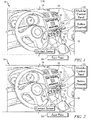
- An illustrative passenger vehicle 10 includes a number of subsystems 12, 13, 14, a display 16, a controller 18, and a modular control panel 20 as shown, for example, in Figs. 1 and 2 .
- the subsystems 12, 13, 14 illustratively provide temperature control functions and infotainment functions to users in the passenger vehicle 10.
- the display 16 is coupled to a dashboard 22 of the passenger vehicle 10 and may be viewed by users in the passenger vehicle 10.
- the controller 18 is illustratively housed in the dashboard 22 and is coupled to the subsystems 12, 13, 14, the display 16, and the modular control panel 20 to direct operation of the subsystems 12, 13, 14 and the display 16.
- the modular control panel 20 receives various user inputs associated with the subsystems 12, 13, 14 and provides signals to the controller 18 indicative of the received user inputs.
- the modular control panel 20 is reconfigurable for use in a variety of passenger vehicles to provide a number of different user interface options and to accommodate a number of different subsystem combinations that may be present in a particular passenger vehicle as suggested in Figs. 1 , 4 , 6 , and 8 .
- the modular control panel 20 shown in Figs. 1-3 illustratively includes a contact sensor 24 that provides a substantially monolithic contact area 25 and a face plate 26 that overlies the contact sensor 24 to engage various predetermined locations within the contact area 25 when manipulated by a user.
- the contact sensor 24 is adapted for use in a variety of passenger vehicles and provides signals associated with a number of subsystem combinations.
- the face plate 26 is interchangeable with other face plates (e.g., face plate 226 shown in Fig. 4 and face plate 326 shown in Fig. 6 ) and provides a particular user interface for a corresponding subsystem combination.
- the contact sensor 24 includes a pressure-sensitive pad 28 and a microcontroller 30 as shown diagrammatically in Fig. 3 .
- the pressure-sensitive pad 28 defines the contact area 25 and detects pressure levels applied at locations within the contact area 25.
- the pressure-sensitive pad 28 is illustratively semi-transparent to allow backlights (Light Emitting Diodes (LEDs)) associated with the modular control panel 20 to shine through the face plate 26 and convey information to a user.
- the microcontroller 30 is coupled to the pressure-sensitive pad 28 and produces signals in response to detection of a pressure input at a preselected location onto the contact area 25.
- the pressure-sensitive pad 28 included in the contact sensor 24 may be replaced by a capacitive pad, an optical sensor, a magnetic field distortion sensor, or another sensing device that detects location-specific interaction within a generally monolithic contact area.
- the location-specific interaction from the face plate 26 may correspond to contacts made by the face plate 26 onto the contact sensor 24 or to contacts made by a user onto the face plate 26 that are subsequently detected by the contact sentor 24.
- the interchangeable face plates 26, 226, 326 may be configured to interact with the particular sensing device used in the modular control panel 20.
- the face plate 26 illustratively extends over the pressure-sensitive pad 28 included in the contact sensor 24 and exerts pressure onto the pressure-sensitive pad 28 in predetermined locations when a user interacts with the face plate 26 as suggested in Figs. 1 and 2 .
- the face plate 26 includes a mount frame 32 and a plurality of control elements 34 coupled to the mount frame 32.
- the mount frame 32 is illustratively rigid and includes a plurality of apertures 36.
- the control elements 34 extend through the apertures 36 formed through the mount frame 32 toward the pressure-sensitive pad 28 and move relative to the mount frame 32 in response to user interaction with particular control elements 34 so that pressure is applied by the control elements 34 onto the pressure-sensitive pad 28.
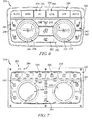
- the control elements 34 of face plate 26 illustratively include a plurality of buttons 41-45 and a plurality of knobs 46-48 as shown in Fig. 5 .
- the buttons 41-45 are coupled to the mount frame 32 to slide relative to the mount frame 32 and are configured exert pressure in preselected positions on the contact sensor 24 when pressed by a user.
- the knobs 46-49 are coupled to the mount frame 32 to rotate relative to the mount frame 32 and exert pressure on the contact sensor 24 in predetermined positions when turned by a user.
- other types of control element such as sliders, switches, and the like may be included in the face plate 26.
- Each button 41-45 illustratively includes a corresponding interface tab 51-55 and contact pin 61-65 as shown in Figs. 4 and 5 .
- the interface tabs 51-55 include markings and/or transparent indicia suggesting the functions controlled by interaction with the button 41-45 and are sized to be pressed by a user.
- the contact pins 61-65 extend from the interface tabs 51-55 toward the contact sensor 24 so that the contact pins 61-65 engage the contact sensor 24 when a user presses the corresponding interface tab 51-55.
- snap domes are coupled between the buttons 41-45 to the mount frame 32 to bias the buttons 41-45 away from the contact sensor 24 and to provide tactile feedback to a user when pressing the buttons 41-45.
- Each button 41-45 is illustratively movable relative to the mount frame 32 between a deactivated position, a touch-activation position, and a push-activation position as suggested in Figs. 1 and 2 .
- a button 41-45 In the deactivated position, a button 41-45 is spaced apart from or in light contact with the contact area 25.
- a button 41-45 In the touch-activation position, a button 41-45 applies a touch-activation pressure on the contact area 25 in response to a user applying a touch force on to the button 41-45 as suggested in Fig. 1 .
- a button 41-45 applies a push-activation pressure, greater than the touch-activation pressure, on the contact area 25 in response to a user applying a press force, greater than the touch force, onto the button 41-45 as suggested in Fig. 2 .
- buttons 41-45 are associated with a temperature control subsystem 12 as suggested in Fig. 3 . More particularly the button 41 is associated with a driver-side seat warmer; the button 42 is associated with a passenger-side seat warmer; the button 43 is associated with a rear-window defroster; the button 44 is associated with an air recirculator; and the button 45 is associated with an air conditioner. In other embodiments, the buttons 41-45 may be associated with an infotainment subsystem 13, a communication subsystem 14, or another subsystem of the passenger vehicle 10.
- Each knob 46-48 illustratively includes a corresponding interface handle 56-58 and contact ball 66-68 as shown in Figs. 4 and 5 .
- the interface handles 56-56 may be gripped and rotated by a user.
- the contact balls 66-68 are coupled to the interface handles 56-58 and engage the contact sensor 24 along a predetermined path when a user turns the corresponding interface handle 56-58.
- the contact balls 66-68 are freely rotating and spring-loaded to reduce wear on the contact air and on the contact balls 66-68 themselves. This arrangement may also mitigate inconsistency in distance between the face plate 26 and the contact area 25.
- Inconsistency in distance between the face plate 26 and the contact area 25 may result from multiple changes of the face plate 26, vibration during operation of the passenger vehicle 10, manufacturing differences, material warping, etc.
- ball-nosed spring detents (not shown) apply pressure onto the knobs 46-48 as the knobs 46-48 rotate to provide tactile feedback to a user when turning the knobs 46-48.
- the knobs 46-48 are associated with the temperature control subsystem 12 as suggested in Fig. 3 . More particularly the knob 46 is associated with a temperature setting; the knob 47 is associated with a fan setting; and the knob 48 is associated with an air-distribution setting. In other embodiments, the knobs 46-48 may be associated with the infotainment subsystem 13, the communication subsystem 14, or another subsystem of the passenger vehicle 10.
- the controller 18 illustratively includes a memory 72 and a processor 74 coupled to the memory 72 as shown diagrammatically in Fig. 3 .
- the memory 72 may be of any type suitable for holding instructions and/or other types of information.
- the processor 74 may be of any type suitable for reading information from the memory 72 and for performing instructions contained therein.
- the controller 18 may provide a function preview when a user touches a button 41-45 before adjusting a parameter when a user pushes the button as suggested in Figs. 1 and 2 . Additionally, more in-depth information about the function controlled by a button 41-45 could be displayed when the button 41-45 is touched before it is pushed. Such a preview could be provided on the display 16 or provided via lights visible through the face plate 26. In one example, the controller 18 may display words indicating that a touched button 42 is associated with a passenger seat warmer parameter and a graphic suggesting that the seat warmer parameter will be increased if the button 42 is pushed as shown in Fig. 1 .
- the controller 18 may then display the words and an updated graphic suggesting that the seat warmer parameter is changed after the button is pushed as shown in Fig. 2 .
- the controller 18 may preview the association and function of touched buttons associated with audio volume parameters, audio track/next track parameters, desired temperature parameters, and other parameters.
- the controller 18 may display indicia suggestive of a parameter that will be changed and/or suggestive of how that parameter will be changed in response to a button 41-45 being moved to the touch-activation position. Further, the controller 18 may change the parameter in response to the button 41-45 being moved to the push-activation position. In some embodiments, the controller 18 may provide such a preview feature when a user touches a knob, switch, slider, or other control element before the user applies a greater input force to move the knob, switch, slider, or other control element.
- the controller 18 may provide pressure-variable adjustment of parameters at different rates based on the amount of pressure applied by a user onto a button 41-45. For example, a parameter could be adjusted more quickly when a user presses hard on a button 41-45 than when a user presses softly on the button 41-45.
- the controller 18 may change a desired temperature parameter at the rate of one degree per second in response to a user pushing a desired temperature button with a first amount of force and may change a desired temperature parameter at the rate of five degrees per second in response to a user pushing the desired temperature button with a second, greater, amount of force.
- Such pressure-sensitive operation may also be applied to changes in fan speeds, audio volume, contact scrolling, and other parameters.
- the controller 18 may adjust a parameter of at least one subsystem at a first rate of change in response to receipt of a signal from the modular control panel 20 associated with a button 41-45 being moved to the push-activation position and maintained in that position by a first amount of force. Further, the controller 18 may adjust the parameter of the at least one subsystem at a second rate of change, greater than the first rate of change, in response to receipt of a signal from the modular control panel 20 associated with the button 41-45 being moved to the push-activation position and maintained in that position by a second amount of force, greater than the first amount of force.
- the pressure-sensitive pad 28 included in the contact sensor 24 provides a single, substantially monolithic contact area 25 as suggested in Figs. 1 and 2 .
- the contact area 25 is unitary and integral to read a pressure/touch event anywhere in the contact area 25.
- Exemplary pressure-sensitive pad 28 that may be used in the modular control panel 20 are available from Tactonic Technologies, LLC of Long Island City, New York. Unlike some Printed Circuit Boards (PCBs) used with specific control elements, the contact area 25 is not divided into separated sensitive regions associated with a particular control element layout.
- modular control panels 20 including the contact sensor 24 may be used with a variety of face plates (e.g., 26, 226, 326) to provide a modular control panel system 80 adapted for use in passenger vehicles for various markets and/or with various trim levels.
- the modular control panel 20 also illustratively includes a face-plate-identification mechanism 82 that determines which face plate 26, 226, 326 is mounted adjacent to the contact sensor 24 as suggested in Fig. 5 .
- the face-plate-identification mechanism 82 allows the microcontroller 30 included in the contact sensor 24 of the modular control panel 20 to provide signals to the controller 18 associated with control elements 34 included in a particular face plate 26, 226, 326 coupled to the contact sensor 24.
- the face-plate-identification mechanism 82 includes a plurality of identification protrusions 84 that extend from the mount frame 32 of the face plate 26 as shown in Fig. 5 .
- the identification protrusions 84 engage the contact area 25 of the contact sensor 24 in a predetermined location when the face plate 26 is mounted adjacent to the contact sensor 24 so that the microcontroller 30 can identify the face plate 26.
- the face-plate-identification mechanism 82 may include a pattern of metallic pins coupled to the face plate 26 that engage at least some complementary metallic contacts coupled to the contact sensor 24. When the pattern of metallic pins engages the complementary metallic contacts, the contact sensor 24 may identify the face plate 26 by comparing the pattern of metallic pins to a list of known face plate patterns.
- the face-plate-identification mechanism 82 may include a Radio Frequency Identification (RFID) tag coupled to the face plate 26 and a corresponding radio frequency sensor coupled to the contact sensor 24. When the RFID tag is moved into close proximity to the radio frequency sensor, the contact sensor 24 may identify the face plate 26.
- RFID Radio Frequency Identification
- other types of identification system may be used to provide the face-plate-identification mechanism 82.
- a second face plate 226 adapted for use in passenger vehicle 10 with contact sensor 24 is shown in Figs. 6 and 7 .
- the face plate 226 is interchangeable with the face plate 26 within modular control panel 20 and, along with the contact sensor 24 and the face plate 26, is part of the modular control panel system 80.
- the face plate 226 may extend over the pressure-sensitive pad 28 included in the contact sensor 24 and to exert pressure onto the pressure-sensitive pad 28 in predetermined locations when a user interacts with the face plate 226 as suggested in Fig. 6 .
- the face plate 226 includes a mount frame 232 and a plurality of control elements 234 coupled to the mount frame 232.
- the mount frame 232 is illustratively rigid and includes a plurality of apertures 236.
- the control elements 234 extend through the apertures 236 formed through the mount frame 232 toward the pressure-sensitive pad 28 and move relative to the mount frame 232 in response to user interaction with particular control elements 234 so that pressure is applied by the control elements 234 onto the pressure-sensitive pad 28.
- the control elements 234 of face plate 226 illustratively include a plurality of buttons 241-245 (among others), a pair of knobs 246, 247, and a pair of linear touch sliders 248, 249 as shown in Fig. 6 .
- the buttons 241-245 are coupled to the mount frame 232 to slide relative to the mount frame 232 and are configured to exert pressure in preselected positions on the contact sensor 24 when pressed by a user.
- the knobs 246, 247 are coupled to the mount frame 232 to rotate relative to the mount frame 232 and exert pressure on the contact sensor 24 in predetermined positions when turned by a user.
- the linear touch sliders 248, 249 are mounted within the knobs 246, 247 and allow pressure exerted by a user during a swipe gesture along the sliders 248, 249 to be transmitted to the contact sensor 24.
- Each button 241-245 illustratively includes a corresponding interface tab 251-255 and contact pin 261-265 as shown in Figs. 6 and 7 .
- the interface tabs 251-255 include markings suggesting the functions controlled by interaction with the button 241-245 and are to be pressed by a user.
- the contact pins 261-265 extend from the interface tabs 251-255 toward the contact sensor 24 so that the contact pins 261-265 engage the contact sensor 24 when a user presses the corresponding interface tab 251-255.
- snap domes are coupled between the buttons 241-245 to the mount frame 232 to bias the buttons 241-245 away from the contact sensor 24 and to provide tactile feedback to a user when pressing the buttons 241-245.
- Each button 241-245 is illustratively movable relative to the mount frame 232 between the deactivated position, the touch-activation position, and the push-activation position as described above.
- the buttons 241-245 are illustratively associated with various parameters of a temperature control subsystem.
- Each knob 246, 247 illustratively includes a corresponding interface handle 256, 257 and contact finger 266, 267 as shown in Figs. 6 and 7 .
- the interface handles 256, 257 may be gripped and rotated by a user.
- the contact fingers 266, 267 are coupled to the interface handles 256, 267 and engage the contact sensor 24 along a predetermined path when a user turns the corresponding interface handle 256, 257.
- the knobs 246, 247 are associated with an infotainment subsystem to control volume and radio channel.
- Each linear touch slider 248, 249 illustratively has a corresponding silicone backing 258, 259 as shown in Figs. 6 and 7 .
- the silicone backing 258, 259 deforms to transmit pressure from a user swiping along the linear touch sliders 248,249 on to the contact sensor 24.
- the linear touch sliders 248, 249 are illustratively associated with fan speed parameters of a temperature control subsystem.
- the second face plate 226 also includes a plurality of identification protrusions 284 that extend from the mount frame 232 of the face plate 226 as part of the face-plate-identification mechanism 82 as shown in Fig. 7 .
- the identification protrusions 284 engage the contact area 25 of the contact sensor 24 in a predetermined location when the face plate 226 is mounted adjacent to the contact sensor 24 so that the microcontroller 30 can identify the face plate 226.
- a third face plate 326 adapted for use in passenger vehicle 10 with contact sensor 24 is shown in Figs. 8 and 9 .
- the face plate 326 is interchangeable with the face plate 26 within modular control panel 20 and, along with the contact sensor 24 and the face plate 26, is part of the modular control panel system 80.
- the face plate 326 may extend over the pressure-sensitive pad 28 included in the contact sensor 24 and to exert pressure onto the pressure-sensitive pad 28 in predetermined locations when a user interacts with the face plate 326 as suggested in Fig. 8 .
- the face plate 326 includes a mount frame 332 and a plurality of control elements 334 coupled to the mount frame 332.
- the mount frame 332 is illustratively rigid and includes a plurality of apertures 336.
- the control elements 334 extend through the apertures 336 formed through the mount frame 332 toward the pressure-sensitive pad 28 and move relative to the mount frame 332 in response to user interaction with particular control elements 334 so that pressure is applied by the control elements 334 onto the pressure-sensitive pad 28.
- the control elements 334 of face plate 326 illustratively include a plurality of buttons 341-345 (among others) and a pair of touch pads 348, 349 as shown in Fig. 8 .
- the buttons 341-345 are coupled to the mount frame 332 to slide relative to the mount frame 332 and are configured exert pressure in preselected positions on the contact sensor 24 when pressed by a user.
- the touch pads 348, 349 allow pressure exerted by a user during a swipe gestures horizontally or vertically along the pads 348, 349 to be transmitted to the contact sensor 24.
- Each button 341-345 includes a corresponding interface tab 351-355 and contact pin (not shown) illustrated, for example, in Figs. 8 and 9 .
- the interface tabs 351-355 include markings suggesting the functions controlled by interaction with the button 341-345 and may be pressed by a user.
- the contact pins 361-365 extend from the interface tabs 351-355 toward the contact sensor 24 so that the contact pins 361-365 engage the contact sensor 24 when a user presses the corresponding interface tab 351-355.
- snap domes 361-365 are coupled between the buttons 341-345 to the mount frame 332 to bias the buttons 341-345 away from the contact sensor 24 and to provide tactile feedback to a user when pressing the buttons 341-345.
- Each button 341-345 is illustratively movable relative to the mount frame 332 between the deactivated position, the touch-activation position, and the push-activation position as described above.
- the buttons 341-345 are illustratively associated with various parameters of a temperature control subsystem.
- the touch pads 348, 349 are illustratively associated with fan speed parameters (horizontal swipes) and temperature parameters (vertical swipes) of a temperature control subsystem.
- the third face plate 326 also includes a plurality of identification protrusions 384 that extend from the mount frame 332 of the face plate 326 as part of the face-plate-identification mechanism 82 as shown in Fig. 9 .
- the identification protrusions 384 engage the contact area 25 of the contact sensor 24 in a predetermined location when the face plate 326 is mounted adjacent to the contact sensor 24 so that the microcontroller 30 can identify the face plate 326.
- a fourth face plate 426 adapted for use in a passenger vehicle with a contact sensor 424 to provide a modular control panel 420 is shown, for example, in Fig. 10 .
- the modular control panel 420 is substantially similar to the modular control panel 20 except the size of the contact sensor 424 and the face plate 426 is adjusted for use in different passenger vehicle applications.
- the contact sensor 424 has a pressure-sensitive pad (not shown) that defines a substantially monolithic contact area 425 as shown in Fig. 10 .
- the face plate 426 illustratively includes a mount frame 432 and a number of control elements 434 as shown in Fig. 10 .
- the control elements 434 illustratively include a number of buttons 441-445 (among others), a pair of knobs 446, 447, and a pivot switch 448 all extending through apertures 436 formed in the mount frame 432.
- the buttons 441-445 (among others), knobs 446, 447, and pivot switch 448 are all mounted to move relative to the mount frame 432.
- a fifth face plate 526 adapted for use in a passenger vehicle with contact sensor 424 is shown in Fig. 11 .
- the face plate 526 is interchangeable with the face plate 426 within modular control panel 420 and, along with the contact sensor 424 and the face plate 426, is part of the modular control panel system 480.
- the face plate 526 illustratively includes a mount frame 532, a flexible membrane 533, and a number of control elements 534 as shown in Fig. 11 .
- the control elements 534 a pair of knobs 546, 547, a plurality of press indentations 591-595 (among others), and a slide indentation 596.
- the knobs 546, 547 extend through the mount frame 532 to engage the contact sensor 424 and rotate relative to the mount frame 532.
- the press indentations 591-595 are formed by the flexible membrane 533 and extend toward the contact sensor 424 so that the flexible membrane 533 transmits pressure to the contact sensor 424 in a predetermined position when a user pushes a press indentation 591-595.
- the slide indentation 596 is formed by the flexible membrane 533 and extends toward the contact sensor 424 along a linear path across a portion of the flexible membrane 533.
- the flexible membrane 533 transmits pressure to the contact sensor 424 along a predetermined path when a user swipes along the slide indentation 596.
- a sixth face plate 626 adapted for use in a passenger vehicle with contact sensor 424 is shown in Fig. 12 .
- the face plate 626 is interchangeable with the face plate 426 within modular control panel 420 and, along with the contact sensor 424 and the face plate 426, is part of the modular control panel system 480.
- the face plate 626 illustratively includes a mount frame 632, a flexible membrane 633, and a number of control elements 634 as shown in Fig. 12 .
- the control elements 634 include a number of press indentations 691-695 (among others) and a pair of circular slider indentations 696, 697.
- the press indentations 691-695 and the circular slider indentations 696, 697 are formed by the flexible membrane 633.
- All the indentations 691-697 extend toward the contact sensor 424 so that the flexible membrane 633 transmits pressure to the contact sensor 424 in a predetermined position when a user pushes a press indentation 691-695 or slides her finger around a circular path associated with a circular slider indentation 696, 697.
- Some passenger vehicles include control panels for receiving and communicating user inputs associated with various subsystems (e.g., temperature control subsystems, communication subsystems, infotainment subsystems, etc.).
- control panels can include a face plate used in conjunction with a face-plate-specific printed circuit board (PCB) that underlies the face plate.
- PCB printed circuit board
- Embodiments of the present disclosure provide a solution to the technical problem that various face plates are needed for use in different applications leading to the need for corresponding face-plate-specific printed circuit boards which can be costly.
- the present disclosure provides a modular control panel system including a contact sensor that may be used with a variety of different face plates.
- control panels used in passenger vehicles can include touch-screen control panels such as Liquid Crystal Displays (LCDs) or other touch-screen interfaces.
- touch-screen control panels such as Liquid Crystal Displays (LCDs) or other touch-screen interfaces.
- LCDs Liquid Crystal Displays
- touch-screen control panels while capable of providing various layouts, presents technical problems relating to the need for tactile feedhack and constantly located control elements.
- Embodiments of the present disclosure provide a solution to the technical problem that some touch-screen control panels that are interoperable in various applications do not provide tactile feedback or constant control element location to a user.
- the present disclosure provides a modular control panel system including control elements that give tactile feedback to a user and that are constantly located over the control panel allowing a user to manipulate the control panel while maintaining a view of the road.
Landscapes
- Engineering & Computer Science (AREA)
- Theoretical Computer Science (AREA)
- General Engineering & Computer Science (AREA)
- Human Computer Interaction (AREA)
- Physics & Mathematics (AREA)
- General Physics & Mathematics (AREA)
- Mechanical Engineering (AREA)
- Transportation (AREA)
- Combustion & Propulsion (AREA)
- Chemical & Material Sciences (AREA)
- User Interface Of Digital Computer (AREA)
- Push-Button Switches (AREA)
- Automation & Control Theory (AREA)
- Steering Controls (AREA)
- Air-Conditioning For Vehicles (AREA)
- Air Bags (AREA)
- Switches That Are Operated By Magnetic Or Electric Fields (AREA)
Applications Claiming Priority (1)
| Application Number | Priority Date | Filing Date | Title |
|---|---|---|---|
| US14/265,559 US9440536B2 (en) | 2014-04-30 | 2014-04-30 | Passenger vehicle with a modular control panel |
Publications (3)
| Publication Number | Publication Date |
|---|---|
| EP2939862A2 true EP2939862A2 (de) | 2015-11-04 |
| EP2939862A3 EP2939862A3 (de) | 2016-03-23 |
| EP2939862B1 EP2939862B1 (de) | 2019-10-16 |
Family
ID=53039256
Family Applications (1)
| Application Number | Title | Priority Date | Filing Date |
|---|---|---|---|
| EP15164980.3A Active EP2939862B1 (de) | 2014-04-30 | 2015-04-24 | Personenfahrzeug mit einem modularen bedienfeld |
Country Status (4)
| Country | Link |
|---|---|
| US (1) | US9440536B2 (de) |
| EP (1) | EP2939862B1 (de) |
| KR (1) | KR101768308B1 (de) |
| CN (1) | CN105539149B (de) |
Cited By (2)
| Publication number | Priority date | Publication date | Assignee | Title |
|---|---|---|---|---|
| FR3061567A1 (fr) * | 2017-01-03 | 2018-07-06 | Hap2U | Interface tactile comportant un capteur de force |
| IT201700058490A1 (it) * | 2017-05-30 | 2018-11-30 | Bitron Spa | Plancia di comando con dispositivo di riscontro aptico. |
Families Citing this family (11)
| Publication number | Priority date | Publication date | Assignee | Title |
|---|---|---|---|---|
| GB2547032B (en) * | 2016-02-05 | 2020-05-20 | Ford Global Tech Llc | A vehicle human interface assembly |
| CN106042837B (zh) * | 2016-06-27 | 2018-07-17 | 北京新能源汽车股份有限公司 | 电动汽车的空气调节系统的控制方法 |
| CN106114130B (zh) * | 2016-06-27 | 2018-07-17 | 北京新能源汽车股份有限公司 | 电动汽车的空气调节系统的控制方法 |
| CN106184064A (zh) * | 2016-07-29 | 2016-12-07 | 芜湖新泉汽车饰件系统有限公司 | 仪表板传感器检测格栅 |
| DE102016216543A1 (de) * | 2016-09-01 | 2018-03-01 | Audi Ag | Bedieneinrichtung für ein Komfortsystem eines Kraftfahrzeugs, Komfortsystem mit einer Bedieneinrichtung und Kraftfahrzeug mit einem Komfortsystem |
| KR102463695B1 (ko) * | 2016-12-12 | 2022-11-08 | 현대자동차주식회사 | 차량용 입력기구 |
| JP6824047B2 (ja) * | 2017-01-20 | 2021-02-03 | 株式会社クボタ | 作業車 |
| US20180246641A1 (en) * | 2017-02-28 | 2018-08-30 | GM Global Technology Operations LLC | Triggering control of a zone using a zone image overlay on an in-vehicle display |
| KR102403356B1 (ko) * | 2017-11-01 | 2022-06-02 | 현대자동차주식회사 | 차량용 컨트롤 패널 |
| DE102018219549A1 (de) * | 2018-11-15 | 2020-05-20 | Zf Friedrichshafen Ag | Bedienelement für ein Fahrzeug, Verfahren und Vorrichtung zum Ansteuern einer Funktion eines Fahrzeugs unter Verwendung eines Bedienelements und Bediensystem |
| US11364857B2 (en) | 2019-01-31 | 2022-06-21 | Toyota Motor Engineering & Manufacturing North America, Inc. | Modular interior vehicle electronics system |
Family Cites Families (18)
| Publication number | Priority date | Publication date | Assignee | Title |
|---|---|---|---|---|
| US5742894A (en) | 1995-02-06 | 1998-04-21 | Motorola, Inc. | Radio communication device having a moveable housing element and keypad disposed therein |
| US20090273574A1 (en) | 1995-06-29 | 2009-11-05 | Pryor Timothy R | Programmable tactile touch screen displays and man-machine interfaces for improved vehicle instrumentation and telematics |
| CA2278832A1 (en) | 1999-01-06 | 2000-07-06 | Vtech Communications, Ltd. | Touch screen overlay apparatus |
| US6642629B2 (en) * | 2000-12-28 | 2003-11-04 | Intel Corporation | Audio system with removable, active faceplate |
| GB0205925D0 (en) | 2002-03-13 | 2002-04-24 | Mcgavigan John Ltd | Improved control panel |
| US6681176B2 (en) * | 2002-05-02 | 2004-01-20 | Robert Bosch Gmbh | Method and device for a detachable navigation system |
| US7226268B2 (en) * | 2004-06-25 | 2007-06-05 | John Gustafson | Faceplate |
| US20050123148A1 (en) * | 2003-11-20 | 2005-06-09 | Ohler Robert E. | Motorcycle audio system |
| JP2008517815A (ja) * | 2004-08-12 | 2008-05-29 | コリンズ・アンド・アイクマン・プロダクツ・コーポレーション | メディア挿通開口部の周囲にデザインされた自動車のセンターコンソール内の電子モジュールのための一体型フェイスプレート |
| US20060046778A1 (en) * | 2004-08-30 | 2006-03-02 | Hembree Ryan M | System for listening to playback of music files by a portable audio device while in a vehicle |
| FR2905195B1 (fr) * | 2006-08-23 | 2008-10-10 | Dav Sa | Module de commande, en particulier pour vehicule automobile |
| US8066319B2 (en) * | 2006-12-01 | 2011-11-29 | Bae Systems Land & Armaments, L.P. | Vehicle emergency egress assembly |
| WO2009047437A2 (fr) * | 2007-09-14 | 2009-04-16 | Delphi Technologies Inc. | Panneaux de controle d'instruments de bord |
| US20100250071A1 (en) * | 2008-03-28 | 2010-09-30 | Denso International America, Inc. | Dual function touch switch with haptic feedback |
| US7995208B2 (en) * | 2008-08-06 | 2011-08-09 | Ftrx Llc | Monolithic interferometer with optics of different material |
| US10150245B2 (en) * | 2008-11-11 | 2018-12-11 | University Of Florida Research Foundation, Inc. | Method of patterning a surface and articles comprising the same |
| DE102009058144B4 (de) | 2009-12-12 | 2023-10-12 | Volkswagen Ag | Verfahren zur Darstellung einer Funktion eines Bedienelements einer Bedienvorrichtung eines Fahrzeugs sowie eine Bedienvorrichtung und ein Fahrzeug |
| US8991772B2 (en) * | 2011-09-02 | 2015-03-31 | Toyota Motor Engineering & Manufacturing North America, Inc. | Instrument panel assembly |
-
2014
- 2014-04-30 US US14/265,559 patent/US9440536B2/en active Active
-
2015
- 2015-04-24 EP EP15164980.3A patent/EP2939862B1/de active Active
- 2015-04-30 KR KR1020150061837A patent/KR101768308B1/ko active Active
- 2015-04-30 CN CN201510426404.1A patent/CN105539149B/zh active Active
Non-Patent Citations (1)
| Title |
|---|
| None |
Cited By (4)
| Publication number | Priority date | Publication date | Assignee | Title |
|---|---|---|---|---|
| FR3061567A1 (fr) * | 2017-01-03 | 2018-07-06 | Hap2U | Interface tactile comportant un capteur de force |
| WO2018127651A1 (fr) * | 2017-01-03 | 2018-07-12 | Hap2U | Interface tactile comportant un capteur de force |
| US10860107B2 (en) | 2017-01-03 | 2020-12-08 | Hap2U | Touch-sensitive interface comprising a force sensor |
| IT201700058490A1 (it) * | 2017-05-30 | 2018-11-30 | Bitron Spa | Plancia di comando con dispositivo di riscontro aptico. |
Also Published As
| Publication number | Publication date |
|---|---|
| CN105539149B (zh) | 2019-10-22 |
| KR101768308B1 (ko) | 2017-08-14 |
| CN105539149A (zh) | 2016-05-04 |
| US20150314683A1 (en) | 2015-11-05 |
| US9440536B2 (en) | 2016-09-13 |
| KR20150125622A (ko) | 2015-11-09 |
| EP2939862A3 (de) | 2016-03-23 |
| EP2939862B1 (de) | 2019-10-16 |
Similar Documents
| Publication | Publication Date | Title |
|---|---|---|
| EP2939862B1 (de) | Personenfahrzeug mit einem modularen bedienfeld | |
| EP3623930B1 (de) | Betriebsvorrichtung | |
| US10120567B2 (en) | System, apparatus and method for vehicle command and control | |
| CN108495766B (zh) | 基于位置的能重新配置的控制旋钮 | |
| US20200089358A1 (en) | Systems and methods for illuminating a track pad system | |
| US10596908B1 (en) | Input apparatus for vehicle | |
| US10996841B2 (en) | Interactive sliding touchbar for automotive display | |
| US20140210795A1 (en) | Control Assembly for a Motor Vehicle and Method for Operating the Control Assembly for a Motor Vehicle | |
| KR20190111095A (ko) | 사람 장치간 인터페이스를 조작하기 위한 방법 및 사람 장치간 인터페이스 | |
| CN105760029A (zh) | 多级开关 | |
| JP5778904B2 (ja) | タッチ式入力装置 | |
| KR102684822B1 (ko) | 입력장치 및 이를 포함하는 차량 | |
| CN107656659A (zh) | 输入系统、检测装置、控制装置、存储介质以及方法 | |
| CN114391131A (zh) | 操作装置 | |
| JP7529380B2 (ja) | 車両用操作制御装置 | |
| US20160170507A1 (en) | Touch pad module, remote input system, and method of controlling a remote input system | |
| CN107107758A (zh) | 信息娱乐系统、交通运输工具和用于操作交通运输工具的信息娱乐系统的设备 | |
| TWI861850B (zh) | 用於車輛的調用功能和操作設置的方法和控制系統 | |
| JP2002140165A (ja) | 電子インタフェース・パネル及び電子機器 | |
| CN106020661A (zh) | 具有内部边框的跟踪板 | |
| GB2441340A (en) | Operator interface sensing a touch position on a movable portion | |
| CN110870204B (zh) | 用于机动车的操作设备,用于借助于操作设备运行机动车的方法,控制装置和机动车 | |
| JP6649127B2 (ja) | 操作装置 | |
| EP4542349B1 (de) | Eingabeanzeigevorrichtung | |
| HK40116122A (zh) | 用於车辆的调用功能和操作设置的方法和控制系统 |
Legal Events
| Date | Code | Title | Description |
|---|---|---|---|
| PUAI | Public reference made under article 153(3) epc to a published international application that has entered the european phase |
Free format text: ORIGINAL CODE: 0009012 |
|
| AK | Designated contracting states |
Kind code of ref document: A2 Designated state(s): AL AT BE BG CH CY CZ DE DK EE ES FI FR GB GR HR HU IE IS IT LI LT LU LV MC MK MT NL NO PL PT RO RS SE SI SK SM TR |
|
| AX | Request for extension of the european patent |
Extension state: BA ME |
|
| PUAL | Search report despatched |
Free format text: ORIGINAL CODE: 0009013 |
|
| AK | Designated contracting states |
Kind code of ref document: A3 Designated state(s): AL AT BE BG CH CY CZ DE DK EE ES FI FR GB GR HR HU IE IS IT LI LT LU LV MC MK MT NL NO PL PT RO RS SE SI SK SM TR |
|
| AX | Request for extension of the european patent |
Extension state: BA ME |
|
| RIC1 | Information provided on ipc code assigned before grant |
Ipc: G06F 1/16 20060101ALI20160216BHEP Ipc: B60H 1/00 20060101ALI20160216BHEP Ipc: G06F 3/0484 20130101ALI20160216BHEP Ipc: B60K 37/06 20060101AFI20160216BHEP Ipc: G06F 3/041 20060101ALI20160216BHEP Ipc: G06F 3/0488 20130101ALI20160216BHEP |
|
| 17P | Request for examination filed |
Effective date: 20160923 |
|
| RBV | Designated contracting states (corrected) |
Designated state(s): AL AT BE BG CH CY CZ DE DK EE ES FI FR GB GR HR HU IE IS IT LI LT LU LV MC MK MT NL NO PL PT RO RS SE SI SK SM TR |
|
| STAA | Information on the status of an ep patent application or granted ep patent |
Free format text: STATUS: EXAMINATION IS IN PROGRESS |
|
| 17Q | First examination report despatched |
Effective date: 20180615 |
|
| GRAP | Despatch of communication of intention to grant a patent |
Free format text: ORIGINAL CODE: EPIDOSNIGR1 |
|
| STAA | Information on the status of an ep patent application or granted ep patent |
Free format text: STATUS: GRANT OF PATENT IS INTENDED |
|
| INTG | Intention to grant announced |
Effective date: 20190508 |
|
| GRAS | Grant fee paid |
Free format text: ORIGINAL CODE: EPIDOSNIGR3 |
|
| GRAA | (expected) grant |
Free format text: ORIGINAL CODE: 0009210 |
|
| STAA | Information on the status of an ep patent application or granted ep patent |
Free format text: STATUS: THE PATENT HAS BEEN GRANTED |
|
| AK | Designated contracting states |
Kind code of ref document: B1 Designated state(s): AL AT BE BG CH CY CZ DE DK EE ES FI FR GB GR HR HU IE IS IT LI LT LU LV MC MK MT NL NO PL PT RO RS SE SI SK SM TR |
|
| REG | Reference to a national code |
Ref country code: GB Ref legal event code: FG4D |
|
| REG | Reference to a national code |
Ref country code: CH Ref legal event code: EP |
|
| REG | Reference to a national code |
Ref country code: DE Ref legal event code: R096 Ref document number: 602015039784 Country of ref document: DE |
|
| REG | Reference to a national code |
Ref country code: IE Ref legal event code: FG4D |
|
| REG | Reference to a national code |
Ref country code: AT Ref legal event code: REF Ref document number: 1190941 Country of ref document: AT Kind code of ref document: T Effective date: 20191115 |
|
| REG | Reference to a national code |
Ref country code: NL Ref legal event code: MP Effective date: 20191016 |
|
| REG | Reference to a national code |
Ref country code: LT Ref legal event code: MG4D |
|
| REG | Reference to a national code |
Ref country code: AT Ref legal event code: MK05 Ref document number: 1190941 Country of ref document: AT Kind code of ref document: T Effective date: 20191016 |
|
| PG25 | Lapsed in a contracting state [announced via postgrant information from national office to epo] |
Ref country code: FI Free format text: LAPSE BECAUSE OF FAILURE TO SUBMIT A TRANSLATION OF THE DESCRIPTION OR TO PAY THE FEE WITHIN THE PRESCRIBED TIME-LIMIT Effective date: 20191016 Ref country code: BG Free format text: LAPSE BECAUSE OF FAILURE TO SUBMIT A TRANSLATION OF THE DESCRIPTION OR TO PAY THE FEE WITHIN THE PRESCRIBED TIME-LIMIT Effective date: 20200116 Ref country code: PT Free format text: LAPSE BECAUSE OF FAILURE TO SUBMIT A TRANSLATION OF THE DESCRIPTION OR TO PAY THE FEE WITHIN THE PRESCRIBED TIME-LIMIT Effective date: 20200217 Ref country code: AT Free format text: LAPSE BECAUSE OF FAILURE TO SUBMIT A TRANSLATION OF THE DESCRIPTION OR TO PAY THE FEE WITHIN THE PRESCRIBED TIME-LIMIT Effective date: 20191016 Ref country code: LT Free format text: LAPSE BECAUSE OF FAILURE TO SUBMIT A TRANSLATION OF THE DESCRIPTION OR TO PAY THE FEE WITHIN THE PRESCRIBED TIME-LIMIT Effective date: 20191016 Ref country code: PL Free format text: LAPSE BECAUSE OF FAILURE TO SUBMIT A TRANSLATION OF THE DESCRIPTION OR TO PAY THE FEE WITHIN THE PRESCRIBED TIME-LIMIT Effective date: 20191016 Ref country code: NO Free format text: LAPSE BECAUSE OF FAILURE TO SUBMIT A TRANSLATION OF THE DESCRIPTION OR TO PAY THE FEE WITHIN THE PRESCRIBED TIME-LIMIT Effective date: 20200116 Ref country code: NL Free format text: LAPSE BECAUSE OF FAILURE TO SUBMIT A TRANSLATION OF THE DESCRIPTION OR TO PAY THE FEE WITHIN THE PRESCRIBED TIME-LIMIT Effective date: 20191016 Ref country code: SE Free format text: LAPSE BECAUSE OF FAILURE TO SUBMIT A TRANSLATION OF THE DESCRIPTION OR TO PAY THE FEE WITHIN THE PRESCRIBED TIME-LIMIT Effective date: 20191016 Ref country code: LV Free format text: LAPSE BECAUSE OF FAILURE TO SUBMIT A TRANSLATION OF THE DESCRIPTION OR TO PAY THE FEE WITHIN THE PRESCRIBED TIME-LIMIT Effective date: 20191016 Ref country code: ES Free format text: LAPSE BECAUSE OF FAILURE TO SUBMIT A TRANSLATION OF THE DESCRIPTION OR TO PAY THE FEE WITHIN THE PRESCRIBED TIME-LIMIT Effective date: 20191016 Ref country code: GR Free format text: LAPSE BECAUSE OF FAILURE TO SUBMIT A TRANSLATION OF THE DESCRIPTION OR TO PAY THE FEE WITHIN THE PRESCRIBED TIME-LIMIT Effective date: 20200117 |
|
| PG25 | Lapsed in a contracting state [announced via postgrant information from national office to epo] |
Ref country code: HR Free format text: LAPSE BECAUSE OF FAILURE TO SUBMIT A TRANSLATION OF THE DESCRIPTION OR TO PAY THE FEE WITHIN THE PRESCRIBED TIME-LIMIT Effective date: 20191016 Ref country code: IS Free format text: LAPSE BECAUSE OF FAILURE TO SUBMIT A TRANSLATION OF THE DESCRIPTION OR TO PAY THE FEE WITHIN THE PRESCRIBED TIME-LIMIT Effective date: 20200224 Ref country code: RS Free format text: LAPSE BECAUSE OF FAILURE TO SUBMIT A TRANSLATION OF THE DESCRIPTION OR TO PAY THE FEE WITHIN THE PRESCRIBED TIME-LIMIT Effective date: 20191016 |
|
| PG25 | Lapsed in a contracting state [announced via postgrant information from national office to epo] |
Ref country code: AL Free format text: LAPSE BECAUSE OF FAILURE TO SUBMIT A TRANSLATION OF THE DESCRIPTION OR TO PAY THE FEE WITHIN THE PRESCRIBED TIME-LIMIT Effective date: 20191016 |
|
| REG | Reference to a national code |
Ref country code: DE Ref legal event code: R097 Ref document number: 602015039784 Country of ref document: DE |
|
| PG2D | Information on lapse in contracting state deleted |
Ref country code: IS |
|
| PG25 | Lapsed in a contracting state [announced via postgrant information from national office to epo] |
Ref country code: EE Free format text: LAPSE BECAUSE OF FAILURE TO SUBMIT A TRANSLATION OF THE DESCRIPTION OR TO PAY THE FEE WITHIN THE PRESCRIBED TIME-LIMIT Effective date: 20191016 Ref country code: RO Free format text: LAPSE BECAUSE OF FAILURE TO SUBMIT A TRANSLATION OF THE DESCRIPTION OR TO PAY THE FEE WITHIN THE PRESCRIBED TIME-LIMIT Effective date: 20191016 Ref country code: CZ Free format text: LAPSE BECAUSE OF FAILURE TO SUBMIT A TRANSLATION OF THE DESCRIPTION OR TO PAY THE FEE WITHIN THE PRESCRIBED TIME-LIMIT Effective date: 20191016 Ref country code: DK Free format text: LAPSE BECAUSE OF FAILURE TO SUBMIT A TRANSLATION OF THE DESCRIPTION OR TO PAY THE FEE WITHIN THE PRESCRIBED TIME-LIMIT Effective date: 20191016 Ref country code: IS Free format text: LAPSE BECAUSE OF FAILURE TO SUBMIT A TRANSLATION OF THE DESCRIPTION OR TO PAY THE FEE WITHIN THE PRESCRIBED TIME-LIMIT Effective date: 20200216 |
|
| REG | Reference to a national code |
Ref country code: DE Ref legal event code: R082 Ref document number: 602015039784 Country of ref document: DE Representative=s name: FDST PATENTANWAELTE FREIER DOERR STAMMLER TSCH, DE |
|
| PLBE | No opposition filed within time limit |
Free format text: ORIGINAL CODE: 0009261 |
|
| STAA | Information on the status of an ep patent application or granted ep patent |
Free format text: STATUS: NO OPPOSITION FILED WITHIN TIME LIMIT |
|
| PG25 | Lapsed in a contracting state [announced via postgrant information from national office to epo] |
Ref country code: SM Free format text: LAPSE BECAUSE OF FAILURE TO SUBMIT A TRANSLATION OF THE DESCRIPTION OR TO PAY THE FEE WITHIN THE PRESCRIBED TIME-LIMIT Effective date: 20191016 Ref country code: SK Free format text: LAPSE BECAUSE OF FAILURE TO SUBMIT A TRANSLATION OF THE DESCRIPTION OR TO PAY THE FEE WITHIN THE PRESCRIBED TIME-LIMIT Effective date: 20191016 Ref country code: IT Free format text: LAPSE BECAUSE OF FAILURE TO SUBMIT A TRANSLATION OF THE DESCRIPTION OR TO PAY THE FEE WITHIN THE PRESCRIBED TIME-LIMIT Effective date: 20191016 |
|
| 26N | No opposition filed |
Effective date: 20200717 |
|
| PG25 | Lapsed in a contracting state [announced via postgrant information from national office to epo] |
Ref country code: SI Free format text: LAPSE BECAUSE OF FAILURE TO SUBMIT A TRANSLATION OF THE DESCRIPTION OR TO PAY THE FEE WITHIN THE PRESCRIBED TIME-LIMIT Effective date: 20191016 Ref country code: MC Free format text: LAPSE BECAUSE OF FAILURE TO SUBMIT A TRANSLATION OF THE DESCRIPTION OR TO PAY THE FEE WITHIN THE PRESCRIBED TIME-LIMIT Effective date: 20191016 |
|
| REG | Reference to a national code |
Ref country code: CH Ref legal event code: PL |
|
| PG25 | Lapsed in a contracting state [announced via postgrant information from national office to epo] |
Ref country code: LU Free format text: LAPSE BECAUSE OF NON-PAYMENT OF DUE FEES Effective date: 20200424 Ref country code: LI Free format text: LAPSE BECAUSE OF NON-PAYMENT OF DUE FEES Effective date: 20200430 Ref country code: FR Free format text: LAPSE BECAUSE OF NON-PAYMENT OF DUE FEES Effective date: 20200430 Ref country code: CH Free format text: LAPSE BECAUSE OF NON-PAYMENT OF DUE FEES Effective date: 20200430 |
|
| REG | Reference to a national code |
Ref country code: BE Ref legal event code: MM Effective date: 20200430 |
|
| PG25 | Lapsed in a contracting state [announced via postgrant information from national office to epo] |
Ref country code: BE Free format text: LAPSE BECAUSE OF NON-PAYMENT OF DUE FEES Effective date: 20200430 |
|
| GBPC | Gb: european patent ceased through non-payment of renewal fee |
Effective date: 20200424 |
|
| PG25 | Lapsed in a contracting state [announced via postgrant information from national office to epo] |
Ref country code: GB Free format text: LAPSE BECAUSE OF NON-PAYMENT OF DUE FEES Effective date: 20200424 Ref country code: IE Free format text: LAPSE BECAUSE OF NON-PAYMENT OF DUE FEES Effective date: 20200424 |
|
| PG25 | Lapsed in a contracting state [announced via postgrant information from national office to epo] |
Ref country code: TR Free format text: LAPSE BECAUSE OF FAILURE TO SUBMIT A TRANSLATION OF THE DESCRIPTION OR TO PAY THE FEE WITHIN THE PRESCRIBED TIME-LIMIT Effective date: 20191016 Ref country code: MT Free format text: LAPSE BECAUSE OF FAILURE TO SUBMIT A TRANSLATION OF THE DESCRIPTION OR TO PAY THE FEE WITHIN THE PRESCRIBED TIME-LIMIT Effective date: 20191016 Ref country code: CY Free format text: LAPSE BECAUSE OF FAILURE TO SUBMIT A TRANSLATION OF THE DESCRIPTION OR TO PAY THE FEE WITHIN THE PRESCRIBED TIME-LIMIT Effective date: 20191016 |
|
| PG25 | Lapsed in a contracting state [announced via postgrant information from national office to epo] |
Ref country code: MK Free format text: LAPSE BECAUSE OF FAILURE TO SUBMIT A TRANSLATION OF THE DESCRIPTION OR TO PAY THE FEE WITHIN THE PRESCRIBED TIME-LIMIT Effective date: 20191016 |
|
| P01 | Opt-out of the competence of the unified patent court (upc) registered |
Effective date: 20230530 |
|
| REG | Reference to a national code |
Ref country code: DE Ref legal event code: R079 Ref document number: 602015039784 Country of ref document: DE Free format text: PREVIOUS MAIN CLASS: B60K0037060000 Ipc: B60K0035100000 |
|
| PGFP | Annual fee paid to national office [announced via postgrant information from national office to epo] |
Ref country code: DE Payment date: 20250429 Year of fee payment: 11 |