EP2939964A1 - Dispositif de poussée pour un dispositif de palettisation avec une surface supérieure tridimensionnelle - Google Patents
Dispositif de poussée pour un dispositif de palettisation avec une surface supérieure tridimensionnelle Download PDFInfo
- Publication number
- EP2939964A1 EP2939964A1 EP15156463.0A EP15156463A EP2939964A1 EP 2939964 A1 EP2939964 A1 EP 2939964A1 EP 15156463 A EP15156463 A EP 15156463A EP 2939964 A1 EP2939964 A1 EP 2939964A1
- Authority
- EP
- European Patent Office
- Prior art keywords
- sliding
- structural
- sacks
- filled
- sliding surface
- Prior art date
- Legal status (The legal status is an assumption and is not a legal conclusion. Google has not performed a legal analysis and makes no representation as to the accuracy of the status listed.)
- Granted
Links
Images



Classifications
-
- B—PERFORMING OPERATIONS; TRANSPORTING
- B65—CONVEYING; PACKING; STORING; HANDLING THIN OR FILAMENTARY MATERIAL
- B65G—TRANSPORT OR STORAGE DEVICES, e.g. CONVEYORS FOR LOADING OR TIPPING, SHOP CONVEYOR SYSTEMS OR PNEUMATIC TUBE CONVEYORS
- B65G57/00—Stacking of articles
- B65G57/02—Stacking of articles by adding to the top of the stack
- B65G57/11—Stacking of articles by adding to the top of the stack the articles being stacked by direct action of the feeding conveyor
- B65G57/14—Stacking of articles by adding to the top of the stack the articles being stacked by direct action of the feeding conveyor the articles being transferred from carriers moving in an endless path adjacent to the stacks
-
- B—PERFORMING OPERATIONS; TRANSPORTING
- B65—CONVEYING; PACKING; STORING; HANDLING THIN OR FILAMENTARY MATERIAL
- B65G—TRANSPORT OR STORAGE DEVICES, e.g. CONVEYORS FOR LOADING OR TIPPING, SHOP CONVEYOR SYSTEMS OR PNEUMATIC TUBE CONVEYORS
- B65G57/00—Stacking of articles
- B65G57/02—Stacking of articles by adding to the top of the stack
- B65G57/09—Stacking of articles by adding to the top of the stack from alongside
- B65G57/10—Stacking of articles by adding to the top of the stack from alongside by devices, e.g. reciprocating, acting directly on articles for horizontal transport to the top of stack
-
- B—PERFORMING OPERATIONS; TRANSPORTING
- B65—CONVEYING; PACKING; STORING; HANDLING THIN OR FILAMENTARY MATERIAL
- B65G—TRANSPORT OR STORAGE DEVICES, e.g. CONVEYORS FOR LOADING OR TIPPING, SHOP CONVEYOR SYSTEMS OR PNEUMATIC TUBE CONVEYORS
- B65G57/00—Stacking of articles
- B65G57/02—Stacking of articles by adding to the top of the stack
- B65G57/16—Stacking of articles of particular shape
- B65G57/20—Stacking of articles of particular shape three-dimensional [3D], e.g. cubiform or cylindrical
- B65G57/22—Stacking of articles of particular shape three-dimensional [3D], e.g. cubiform or cylindrical in layers each of predetermined arrangement
- B65G57/24—Stacking of articles of particular shape three-dimensional [3D], e.g. cubiform or cylindrical in layers each of predetermined arrangement the layers being transferred as a whole, e.g. on pallets
-
- B—PERFORMING OPERATIONS; TRANSPORTING
- B65—CONVEYING; PACKING; STORING; HANDLING THIN OR FILAMENTARY MATERIAL
- B65G—TRANSPORT OR STORAGE DEVICES, e.g. CONVEYORS FOR LOADING OR TIPPING, SHOP CONVEYOR SYSTEMS OR PNEUMATIC TUBE CONVEYORS
- B65G2201/00—Indexing codes relating to handling devices, e.g. conveyors, characterised by the type of product or load being conveyed or handled
- B65G2201/02—Articles
- B65G2201/0235—Containers
- B65G2201/0238—Bags
Definitions
- the present invention relates to a sliding device for a palletizing device for stacking filled bags into a stack of sacks.
- palletizers are used to stack individual filled bags into a stack of sacks. This serves for better transportability and improved shelf life of the filled bags.
- individual layers are usually formed, which may have two or more rows of filled sacks. The individual layers are stacked to form the sack stack.
- a sliding device is usually provided in the palletizing device.
- the Sliding device has a sliding surface and a sliding table, wherein the layers are formed on the sliding surface. After forming the respective layer, this layer is moved from the sliding surface by means of a slider to the adjacent sliding table. This movement is usually transverse to the feed motion and the filled sacks of a separate feed device. Thus, usually a lateral feeding of the filled bags and a straight pushing the position of the filled bags on the sliding table.
- a disadvantage of the known devices is that a high frictional force must be overcome for the movement of the position by means of the slider on the sliding table.
- the filled sacks have a large contact surface with the sliding surface, so that a high friction surface with the correspondingly usually high weight of the filled sacks leads to a high resistance to friction. This can lead to high wear or even damage to the filled bags during the sliding process.
- Known solutions such. As a non-stick coating or a complex air cushion, are not able to remedy the disadvantages entirely. Thus, non-stick coatings are only temporary use, since they are also subject to high wear due to the high friction.
- the formation of an active air cushion is associated with a very high design complexity, so that neither the space nor the cost factor is sufficiently taken into account here.
- a sliding device according to the invention for a palletizing device for stacking filled sacks to form a sack stack has a sliding surface.
- a sliding table is arranged.
- a slider is provided for pushing the bags from the sliding surface to the sliding table.
- the sliding device according to the invention is characterized in that the sliding surface has at least one structure section with a three-dimensional surface structure for reducing the friction when pushing the bags.
- a sliding device is thus basically based on known sliding devices.
- the filled sacks for forming the layer are also fed laterally onto the sliding surface in a sliding device according to the invention.
- this finished position of the filled bags is pushed onto the sliding table with the aid of the slider.
- the sliding table can open, so that the formed layer can lower to a lifting device or an already finished and piled up position below the lifting table.
- the forming stack of sacks can be moved downwards via the lifting device so that the sliding table can close again. Then the process starts again.
- the sliding surface is formed with a structural portion having a three-dimensional surface structure.
- This three-dimensional surface structure serves the function of reducing the friction during pushing.
- Under a three-dimensional surface structure is to be understood as a surface of the structural portion, which z. B. has by surveys or depressions a three-dimensional expression.
- this surface structure can also be understood as an increasing or deepening surface structure. In sum, this results in the sum of the contact areas between a filled sack sliding down over it as compared to a flat contact surface This three-dimensional surface structure is significantly reduced.
- the filled sacks will touch the structural section only in the region of the elevations and not in the valleys between the elevations. This reduces the contact surface, which accordingly reduces the resistance by friction. If, however, the three-dimensional surface structure z. B. formed by depressions, then a filled sack will not touch the structure portion in the recessed areas just during the sliding process. In the same way, therefore, there is the possibility of a reduction of the contact surface and thus a reduction of the resistance by friction.
- a static and thus passive air cushion is generated according to the invention. While air is blown in known solutions in active nature, to ensure by appropriate openings a floating or floating of the filled bags, so to speak, a passive or static air cushion is guaranteed by the three-dimensional surface structure according to the present invention. Due to the fact that in valley areas between elevations of the three-dimensional surface structure or in corresponding wells no contact with the filled bag during the sliding process, but there remains an empty volume filled with air, there adhesion can be particularly effectively avoided. Thus, so to speak, a static air cushion in addition to the friction reduction by reducing the contact surface ensure easier sliding.
- an inventive design of the structure section now leads to the sliding process can take place with less resistance. On the one hand, this leads to less wear of the structural section itself and thus the sliding surface. Next, a lesser amount of force can go hand in hand with a smaller and thus more cost-effective drive device for the slide. Last but not least, the sliding process now also takes place in a gentler manner, so that the surface of the filled bags is loaded with less mechanical interference during the sliding process. Also a Local sticking, especially during pauses in the sliding process, is effectively avoided by the described static or passive air cushion.
- the structural portion is provided in a region in which the filled sacks perform a movement during the sliding operation. Accordingly, it is preferred if the entire movement region over which the filled sacks slide from the sliding surface onto the sliding table during the sliding process is provided with a corresponding structural section.
- the sliding table may preferably also have corresponding structural sections. Accordingly, it is therefore also preferred if the structural section or the structural sections have a width which corresponds to the maximum width of the forming layer of the filled sacks.
- the sliding surface may have a sliding portion, which corresponds to the sliding movement, so that this sliding portion is substantially completely formed as a structural portion.
- the at least one structural section extends over the entire sliding width.
- the sliding width can be understood to mean that with the maximum width of the position of the filled bags, the sliding width is necessary to carry out the sliding operation.
- the structural section now extends over the entire sliding width in accordance with the invention, the corresponding reduction of the resistance force can also be made available over the entire sliding width.
- the inventive advantages thus reach over the entire sliding width to the effect. It is also preferred if the structural section has the extension not only over the entire sliding width, but also over the entire or essentially the entire sliding length in order to be able to ensure the advantages of the present invention over the entire path section of the sliding process.
- the sliding table has at least one structural section.
- the sliding table itself preferably also has a structural section.
- a part of the sliding table can be designed as a sliding surface, so that only the sliding table can have a corresponding structural portion.
- the advantages of the design of the structural section in the region of the sliding table are identical to the advantages described for the sliding surface. It is preferred if a corresponding structural section is provided on all sections which act as a contact surface to the pushed sacks during the sliding process.
- the sliding surface has at least one sliding band, wherein the at least one structural portion is arranged adjacent in the sliding direction of the slider next to the sliding band. Since, as is known, feeding usually takes place from the side, the filled sacks must still be moved from a feed position to a pushing position.
- a sliding band can be used in the sliding device, which forms a part of the sliding surface.
- the sliding band itself has a corresponding structural portion or is designed as a structural sliding band.
- the at least one structural portion adjacent, in particular directly adjacent in the sliding direction of the slider is disposed adjacent to the sliding band.
- the slider moves the filled bags from the sliding band down on the adjacent structure section.
- the effect of the reduced resistance force according to the invention now occurs directly, so that the advantages according to the invention have an immediate effect on the sliding process.
- two or more sliding bands may be provided when two or more supply belts to be used in the supply device.
- the transitions between the respective sliding band and the structural section can be made smooth, so that in particular an overlap in this area avoids a gap formation.
- a further advantage may be if, in a sliding device according to the invention, the at least one structural section has elevations and / or depressions, in particular in an embossed manner.
- these are surveys and / or recesses around advantageous embodiments of the three-dimensional surface structure.
- a formative training can be provided in particular by a cold deformation.
- the embossed manner is thus a particularly simple and cost-effective production possibility for the structural section.
- the structural portion separately or integrally with the sliding surface z. B. are formed of a metal sheet.
- the at least one structural section has a multiplicity of structural elements which have the same or essentially the same orientation.
- the alignment is preferably along the sliding direction.
- the individual structural elements may have an elongated shape, which coincide with their main extension direction with the sliding direction.
- a transverse alignment is also conceivable in order to prevent a correspondingly further reduction and above all an undesired slipping of the filled sacks.
- the guiding functionality serves, in particular, to prevent a lateral breakage of the filled sacks, so that after forming the respective layer on the sliding surface, the positional position relative to one another for the individual filled sacks can also be retained with a higher probability.
- the respective embossing point and thus the respective elevation and / or the respective depression can be understood in each case as a structural element.
- the plurality of structural elements are arranged offset to one another in the sliding direction of the slide in a sliding device according to the invention.
- the individual structural elements can be designed transversely to the sliding direction in rows, wherein the subsequent row has an offset in the sliding direction.
- the individual rows overlap one another in the sliding direction and thus a lowering of the filled bag when sliding over the structural elements is particularly effectively avoided.
- the offset in the sliding direction is preferably formed in the region of about half of the elongate alignment of the structural elements, so that a substantially always the same contact between all structural elements and the respective filled bag remains while the sliding operation is performed.
- the plurality of structural elements may also be advantageous if, in a sliding device according to the invention, the plurality of structural elements have different structural heights.
- a ripple can be generated, which provides a reduction or a defined and desired increase in the resistance in defined sections.
- the sliding speed can be influenced in a geometric and constructive manner.
- an additional air cushion is formed by the waviness, which further reduces the frictional force and thus the resistance force in a static manner between the individual higher structural heights.
- the at least one structural section is formed as a separate structural plate of the sliding surface.
- a separate structural plate is also produced separately from the sliding surface and can therefore be produced more cheaply and easily.
- a structural plate can be used in a separate embodiment in the sliding surface and above all be replaced, so that with recognizable wear over the useful life of an exchange of this wearing part is possible. In the assembly, a reduction of the effort is also recognizable, since the geometric dimensions of the sliding surface can now be formed independently of the structural plate.
- a further advantage may be, if in a sliding device according to the invention between the sliding surface and the sliding table, there is a height offset, which is overcome in particular stepwise by the at least one structural portion.
- a vertical offset in the sliding direction downwards serves, so to speak, gradually to support the sliding process. Since in this way an overlapping of the individual stages is possible in addition, gaps between the individual stages can be effectively avoided and thus a risk of jamming or crushing of the filled sacks are almost excluded.
- the overcoming of the height offset takes place in particular by the structure section, which is preferably designed as a separate structural plate in this embodiment.
- Fig. 1 is shown schematically how the stacking process of a bag stack 240 can take place.
- a pallet 300 can be arranged on a lifting device 140.
- On this pallet 300 already a plurality of layers 230 are arranged, which are part of the forming sack stack 240.
- Another layer 230 to be stacked of the filled sacks 200 is still above on the sliding table 114.
- the sliding table 114 is divided and can open outwards along the two arrows, so that the layer 230 of the filled sacks arranged there can sink and come into contact with the sack stack 240 passes.
- the entire stack of sacks 240 is now at least the sack width with the new uppermost layer 230 lowered, so that the sliding table 114 can close again. Subsequently, the sliding table can accommodate the next layer 230 of the filled sacks.
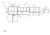
- Fig. 2 and 3 show the previous steps.
- a manufacturing device 400 in the palletizer 100 a plurality of filled bags are provided.
- the production device z. B. as so-called form-fill-and-seal machine filled bags 200 produce.
- a changeover of the rotational alignment of the filled sacks 200 can take place via a switch shown schematically by means of a turning device 130. This makes it possible to achieve different positional images for different positional orientations of the layers 230.
- a feed device 10 with here two feed belts 20 is provided with separate drive devices 30. The feed takes place here in two simultaneous rows 210, so that the layer 230 is also formed with two rows 210 of the filled sacks 200.
- the formation of the situation takes place on the sliding surface 112th
- a movement of the filled bags 200 must take place.
- the filled sacks 200 slide along the sliding surface 112 and along the sliding table 114.
- a structural portion 120 is now provided at least in the region of the sliding surface 112.
- the sliding table 114 may have one or more corresponding structural sections 120. In the following figures, different embodiments of inventive structural sections 120 are explained in more detail.
- Fig. 4 shows a first way to form a structural portion 120.
- the individual structural elements 126 are formed as elevations 124a, which thus result in a three-dimensional surface structure 122 with a structural height 126a.
- the structure height 126a is constant.
- the filled bag 200 can now be moved to the right with the aid of the slider 116 along the sliding direction SR.
- the structural elements 126 now the actual contact surface to the filled bag 200.
- the resistance is reduced by appropriate friction.
- a static or passive air cushion is formed between the structural portion 120, namely the valley area, and the filled bag 200, pushing is further facilitated in terms of the necessary pushing force.
- Fig. 5 shows a schematic side view of a similar embodiment Fig. 4 , however, here the structure portion 120 is formed with a surface structure 122 having a plurality of recesses 124b. Each of these depressions 124b thus forms a single structural element 126.
- the resistance force is reduced by reducing the contact area and by forming a static or passive air cushion.
- Fig. 6 is shown as in plan view of a structural portion 120 over the entire sliding width SB a corresponding formation of the structural portion 120 can be carried out.
- the individual structural elements 126 are formed in rows here in order to form the corresponding three-dimensional surface structure 122.
- the Fig. 7 shows an evolution of the Fig. 6 , wherein the individual rows of the structural elements 126 in the sliding direction SR offset from each other, in particular formed overlapping and arranged.
- Fig. 8 it is shown how a height offset can be compensated during the sliding process.
- two sliding bands 113 are provided here in the area of the sliding surface 112 in order to move the supplied filled sacks 200 each from a supply position into a sliding position.
- the structural sections 122 are formed as separate structural plates 128.
- the separate structural plates 128 are preferably interchangeable designed.
- About the height offset can be additionally avoided by the overlap shown gap formation, so that a risk of jamming or crushing during the sliding operation can be completely avoided.
Landscapes
- Engineering & Computer Science (AREA)
- Mechanical Engineering (AREA)
- Sheets, Magazines, And Separation Thereof (AREA)
- Bag Frames (AREA)
Applications Claiming Priority (1)
| Application Number | Priority Date | Filing Date | Title |
|---|---|---|---|
| DE102014105930.1A DE102014105930A1 (de) | 2014-04-28 | 2014-04-28 | Schiebevorrichtung für eine Palettiervorrichtung |
Publications (2)
| Publication Number | Publication Date |
|---|---|
| EP2939964A1 true EP2939964A1 (fr) | 2015-11-04 |
| EP2939964B1 EP2939964B1 (fr) | 2017-06-28 |
Family
ID=52577715
Family Applications (1)
| Application Number | Title | Priority Date | Filing Date |
|---|---|---|---|
| EP15156463.0A Not-in-force EP2939964B1 (fr) | 2014-04-28 | 2015-02-25 | Dispositif de poussée pour un dispositif de palettisation avec une surface supérieure tridimensionnelle |
Country Status (3)
| Country | Link |
|---|---|
| US (1) | US20150307292A1 (fr) |
| EP (1) | EP2939964B1 (fr) |
| DE (1) | DE102014105930A1 (fr) |
Families Citing this family (4)
| Publication number | Priority date | Publication date | Assignee | Title |
|---|---|---|---|---|
| IT201700101384A1 (it) * | 2017-09-11 | 2019-03-11 | Ocme Srl | Dispositivo di presa strato a strisciamento e relativo metodo di trasferimento di strati. |
| US10899562B2 (en) * | 2017-12-27 | 2021-01-26 | The Procter & Gamble Company | Apparatus for transferring and/or stacking products |
| US10882705B2 (en) * | 2017-12-27 | 2021-01-05 | The Procter & Gamble Company | Method for transferring and/or stacking products |
| DE102022119392A1 (de) * | 2022-08-02 | 2024-02-08 | Newtec Bag Palletizing | Ablegetisch |
Citations (6)
| Publication number | Priority date | Publication date | Assignee | Title |
|---|---|---|---|---|
| GB620724A (en) * | 1946-10-24 | 1949-03-29 | Austin Richard Palmer | Improvements in and relating to chutes and the like for bread or biscuit dough pieces |
| GB897835A (en) * | 1959-12-07 | 1962-05-30 | Drohmann Gmbh C | Apparatus for forming stacks of packages |
| JPS52137866A (en) * | 1976-05-11 | 1977-11-17 | Oishi Sangiyou Kk | Pallet stacking device of stacked bag |
| US4214848A (en) * | 1977-02-25 | 1980-07-29 | Precision Industries, Inc. | Palletizer |
| JPH01252421A (ja) * | 1988-03-30 | 1989-10-09 | Hitachi Plant Eng & Constr Co Ltd | ワーク段積装置 |
| EP1437458A1 (fr) * | 2001-10-16 | 2004-07-14 | Shin Caterpillar-Mitsubishi Co., Ltd. | Structure antiderapante |
Family Cites Families (5)
| Publication number | Priority date | Publication date | Assignee | Title |
|---|---|---|---|---|
| US3624782A (en) * | 1969-04-14 | 1971-11-30 | Aircraft Mechanics | Semiautomatic palletizer |
| US4593571A (en) * | 1984-12-14 | 1986-06-10 | Schwarz John F | Linear actuator |
| US4708564A (en) * | 1986-07-07 | 1987-11-24 | Master Conveyor Corporation | Palletizing apparatus |
| US5540545A (en) * | 1995-04-07 | 1996-07-30 | Marquip, Inc. | Palletizing system |
| US5868549A (en) * | 1997-08-29 | 1999-02-09 | Hk Systems, Inc. | Palletizer with air assisted slide plate assembly and indexing pallet hoist |
-
2014
- 2014-04-28 DE DE102014105930.1A patent/DE102014105930A1/de not_active Ceased
-
2015
- 2015-02-25 EP EP15156463.0A patent/EP2939964B1/fr not_active Not-in-force
- 2015-04-27 US US14/696,489 patent/US20150307292A1/en not_active Abandoned
Patent Citations (6)
| Publication number | Priority date | Publication date | Assignee | Title |
|---|---|---|---|---|
| GB620724A (en) * | 1946-10-24 | 1949-03-29 | Austin Richard Palmer | Improvements in and relating to chutes and the like for bread or biscuit dough pieces |
| GB897835A (en) * | 1959-12-07 | 1962-05-30 | Drohmann Gmbh C | Apparatus for forming stacks of packages |
| JPS52137866A (en) * | 1976-05-11 | 1977-11-17 | Oishi Sangiyou Kk | Pallet stacking device of stacked bag |
| US4214848A (en) * | 1977-02-25 | 1980-07-29 | Precision Industries, Inc. | Palletizer |
| JPH01252421A (ja) * | 1988-03-30 | 1989-10-09 | Hitachi Plant Eng & Constr Co Ltd | ワーク段積装置 |
| EP1437458A1 (fr) * | 2001-10-16 | 2004-07-14 | Shin Caterpillar-Mitsubishi Co., Ltd. | Structure antiderapante |
Also Published As
| Publication number | Publication date |
|---|---|
| US20150307292A1 (en) | 2015-10-29 |
| EP2939964B1 (fr) | 2017-06-28 |
| DE102014105930A1 (de) | 2015-10-29 |
Similar Documents
| Publication | Publication Date | Title |
|---|---|---|
| EP2881347B1 (fr) | Dispositif de palettisation et son procédé de fonctionnement | |
| EP2939959B1 (fr) | Dispositif de palettisation pour un empilement de sacs pleins | |
| EP2832667B1 (fr) | Procédé et dispositif d'empilement et/ou de palettisation de couches de paquets ou de pièces | |
| EP2939964B1 (fr) | Dispositif de poussée pour un dispositif de palettisation avec une surface supérieure tridimensionnelle | |
| DE2364751C3 (de) | Vorrichtung zur Herstellung eines Stapels von Paketschichten | |
| WO2016156220A1 (fr) | Installation de palettisation et procédé de palettisation mécanique d'objets | |
| EP2103556A1 (fr) | Dispositif de palettisation | |
| EP2939965B1 (fr) | Dispositif de poussée pour un dispositif de palettisation avec un poussoir, un guide d'arrêt en butée et deux guides latéraux | |
| EP2939963B1 (fr) | Dispositif d'alimentation destiné à alimenter en sacs remplis un dispositif de palettisation | |
| EP2581331B1 (fr) | Dispositif et procédé d'alignement de produits | |
| DE2332988A1 (de) | Verfahren und vorrichtung zum entladen und stapeln von gegenstaenden, insbesondere von ziegeln | |
| EP4375221A1 (fr) | Machine pour empiler et désempiler des palettes | |
| DE102016225499A1 (de) | Verfahren und Vorrichtung zum Überführen einer palettierfähigen Lage auf eine zugeordnete Palette | |
| EP3129311A1 (fr) | Procédé et dispositif permettant de déplacer horizontalement des groupes d'articles | |
| WO2017129720A1 (fr) | Dispositif d'empilage et de désempilage de moules | |
| DE102014213520B4 (de) | Vorrichtung zum Stapeln von Gegenständen | |
| EP2133271A1 (fr) | Dispositif et procédé de transmission de marchandises sur un système de transport de marchandises ou sur un dispositif de stockage | |
| EP3210917A1 (fr) | Stockage vertical avec moyens de levage pour marchandises | |
| EP2133293A1 (fr) | Dispositif de transmission de marchandises sur un système de transport de marchandises ou sur un dispositif de stockage | |
| EP2939957B1 (fr) | Dispositif d'alimentation destiné à alimenter en sacs remplis un dispositif de palettisation | |
| DE60212212T2 (de) | Verfahren und Maschine zum Bilden von geordneten Gruppen von Papierrollen | |
| DE102013114014B4 (de) | Durchlaufofen zum Erwärmen von Metallplatinen | |
| EP2621839B1 (fr) | Installation et procédé pour déposer des unités d' emballage sur des palettes de transport en rangées et/ou en colonnes | |
| EP3841045B1 (fr) | Dispositif de palettisation et procédé pour faire fonctionner un dispositif de palettisation | |
| EP1851144A1 (fr) | Dispositif de rotation |
Legal Events
| Date | Code | Title | Description |
|---|---|---|---|
| PUAI | Public reference made under article 153(3) epc to a published international application that has entered the european phase |
Free format text: ORIGINAL CODE: 0009012 |
|
| AK | Designated contracting states |
Kind code of ref document: A1 Designated state(s): AL AT BE BG CH CY CZ DE DK EE ES FI FR GB GR HR HU IE IS IT LI LT LU LV MC MK MT NL NO PL PT RO RS SE SI SK SM TR |
|
| AX | Request for extension of the european patent |
Extension state: BA ME |
|
| 17P | Request for examination filed |
Effective date: 20160504 |
|
| RBV | Designated contracting states (corrected) |
Designated state(s): AL AT BE BG CH CY CZ DE DK EE ES FI FR GB GR HR HU IE IS IT LI LT LU LV MC MK MT NL NO PL PT RO RS SE SI SK SM TR |
|
| GRAP | Despatch of communication of intention to grant a patent |
Free format text: ORIGINAL CODE: EPIDOSNIGR1 |
|
| STAA | Information on the status of an ep patent application or granted ep patent |
Free format text: STATUS: GRANT OF PATENT IS INTENDED |
|
| RIC1 | Information provided on ipc code assigned before grant |
Ipc: B65G 57/22 20060101AFI20170110BHEP Ipc: B65G 47/66 20060101ALN20170110BHEP |
|
| RIC1 | Information provided on ipc code assigned before grant |
Ipc: B65G 57/22 20060101AFI20170117BHEP Ipc: B65G 47/66 20060101ALN20170117BHEP |
|
| INTG | Intention to grant announced |
Effective date: 20170130 |
|
| GRAS | Grant fee paid |
Free format text: ORIGINAL CODE: EPIDOSNIGR3 |
|
| GRAA | (expected) grant |
Free format text: ORIGINAL CODE: 0009210 |
|
| STAA | Information on the status of an ep patent application or granted ep patent |
Free format text: STATUS: THE PATENT HAS BEEN GRANTED |
|
| GRAL | Information related to payment of fee for publishing/printing deleted |
Free format text: ORIGINAL CODE: EPIDOSDIGR3 |
|
| GRAS | Grant fee paid |
Free format text: ORIGINAL CODE: EPIDOSNIGR3 |
|
| AK | Designated contracting states |
Kind code of ref document: B1 Designated state(s): AL AT BE BG CH CY CZ DE DK EE ES FI FR GB GR HR HU IE IS IT LI LT LU LV MC MK MT NL NO PL PT RO RS SE SI SK SM TR |
|
| REG | Reference to a national code |
Ref country code: GB Ref legal event code: FG4D Free format text: NOT ENGLISH |
|
| REG | Reference to a national code |
Ref country code: CH Ref legal event code: EP |
|
| REG | Reference to a national code |
Ref country code: AT Ref legal event code: REF Ref document number: 904642 Country of ref document: AT Kind code of ref document: T Effective date: 20170715 |
|
| REG | Reference to a national code |
Ref country code: IE Ref legal event code: FG4D Free format text: LANGUAGE OF EP DOCUMENT: GERMAN |
|
| REG | Reference to a national code |
Ref country code: DE Ref legal event code: R096 Ref document number: 502015001303 Country of ref document: DE |
|
| PG25 | Lapsed in a contracting state [announced via postgrant information from national office to epo] |
Ref country code: NO Free format text: LAPSE BECAUSE OF FAILURE TO SUBMIT A TRANSLATION OF THE DESCRIPTION OR TO PAY THE FEE WITHIN THE PRESCRIBED TIME-LIMIT Effective date: 20170928 Ref country code: GR Free format text: LAPSE BECAUSE OF FAILURE TO SUBMIT A TRANSLATION OF THE DESCRIPTION OR TO PAY THE FEE WITHIN THE PRESCRIBED TIME-LIMIT Effective date: 20170929 Ref country code: LT Free format text: LAPSE BECAUSE OF FAILURE TO SUBMIT A TRANSLATION OF THE DESCRIPTION OR TO PAY THE FEE WITHIN THE PRESCRIBED TIME-LIMIT Effective date: 20170628 Ref country code: FI Free format text: LAPSE BECAUSE OF FAILURE TO SUBMIT A TRANSLATION OF THE DESCRIPTION OR TO PAY THE FEE WITHIN THE PRESCRIBED TIME-LIMIT Effective date: 20170628 Ref country code: HR Free format text: LAPSE BECAUSE OF FAILURE TO SUBMIT A TRANSLATION OF THE DESCRIPTION OR TO PAY THE FEE WITHIN THE PRESCRIBED TIME-LIMIT Effective date: 20170628 |
|
| REG | Reference to a national code |
Ref country code: NL Ref legal event code: MP Effective date: 20170628 |
|
| REG | Reference to a national code |
Ref country code: LT Ref legal event code: MG4D |
|
| PG25 | Lapsed in a contracting state [announced via postgrant information from national office to epo] |
Ref country code: SE Free format text: LAPSE BECAUSE OF FAILURE TO SUBMIT A TRANSLATION OF THE DESCRIPTION OR TO PAY THE FEE WITHIN THE PRESCRIBED TIME-LIMIT Effective date: 20170628 Ref country code: RS Free format text: LAPSE BECAUSE OF FAILURE TO SUBMIT A TRANSLATION OF THE DESCRIPTION OR TO PAY THE FEE WITHIN THE PRESCRIBED TIME-LIMIT Effective date: 20170628 Ref country code: LV Free format text: LAPSE BECAUSE OF FAILURE TO SUBMIT A TRANSLATION OF THE DESCRIPTION OR TO PAY THE FEE WITHIN THE PRESCRIBED TIME-LIMIT Effective date: 20170628 Ref country code: NL Free format text: LAPSE BECAUSE OF FAILURE TO SUBMIT A TRANSLATION OF THE DESCRIPTION OR TO PAY THE FEE WITHIN THE PRESCRIBED TIME-LIMIT Effective date: 20170628 Ref country code: BG Free format text: LAPSE BECAUSE OF FAILURE TO SUBMIT A TRANSLATION OF THE DESCRIPTION OR TO PAY THE FEE WITHIN THE PRESCRIBED TIME-LIMIT Effective date: 20170928 |
|
| PG25 | Lapsed in a contracting state [announced via postgrant information from national office to epo] |
Ref country code: SK Free format text: LAPSE BECAUSE OF FAILURE TO SUBMIT A TRANSLATION OF THE DESCRIPTION OR TO PAY THE FEE WITHIN THE PRESCRIBED TIME-LIMIT Effective date: 20170628 Ref country code: RO Free format text: LAPSE BECAUSE OF FAILURE TO SUBMIT A TRANSLATION OF THE DESCRIPTION OR TO PAY THE FEE WITHIN THE PRESCRIBED TIME-LIMIT Effective date: 20170628 Ref country code: EE Free format text: LAPSE BECAUSE OF FAILURE TO SUBMIT A TRANSLATION OF THE DESCRIPTION OR TO PAY THE FEE WITHIN THE PRESCRIBED TIME-LIMIT Effective date: 20170628 Ref country code: CZ Free format text: LAPSE BECAUSE OF FAILURE TO SUBMIT A TRANSLATION OF THE DESCRIPTION OR TO PAY THE FEE WITHIN THE PRESCRIBED TIME-LIMIT Effective date: 20170628 |
|
| REG | Reference to a national code |
Ref country code: FR Ref legal event code: PLFP Year of fee payment: 4 |
|
| PG25 | Lapsed in a contracting state [announced via postgrant information from national office to epo] |
Ref country code: ES Free format text: LAPSE BECAUSE OF FAILURE TO SUBMIT A TRANSLATION OF THE DESCRIPTION OR TO PAY THE FEE WITHIN THE PRESCRIBED TIME-LIMIT Effective date: 20170628 Ref country code: IS Free format text: LAPSE BECAUSE OF FAILURE TO SUBMIT A TRANSLATION OF THE DESCRIPTION OR TO PAY THE FEE WITHIN THE PRESCRIBED TIME-LIMIT Effective date: 20171028 Ref country code: PL Free format text: LAPSE BECAUSE OF FAILURE TO SUBMIT A TRANSLATION OF THE DESCRIPTION OR TO PAY THE FEE WITHIN THE PRESCRIBED TIME-LIMIT Effective date: 20170628 Ref country code: SM Free format text: LAPSE BECAUSE OF FAILURE TO SUBMIT A TRANSLATION OF THE DESCRIPTION OR TO PAY THE FEE WITHIN THE PRESCRIBED TIME-LIMIT Effective date: 20170628 |
|
| REG | Reference to a national code |
Ref country code: DE Ref legal event code: R097 Ref document number: 502015001303 Country of ref document: DE |
|
| PG25 | Lapsed in a contracting state [announced via postgrant information from national office to epo] |
Ref country code: DK Free format text: LAPSE BECAUSE OF FAILURE TO SUBMIT A TRANSLATION OF THE DESCRIPTION OR TO PAY THE FEE WITHIN THE PRESCRIBED TIME-LIMIT Effective date: 20170628 |
|
| PGFP | Annual fee paid to national office [announced via postgrant information from national office to epo] |
Ref country code: DE Payment date: 20180228 Year of fee payment: 4 |
|
| PLBE | No opposition filed within time limit |
Free format text: ORIGINAL CODE: 0009261 |
|
| STAA | Information on the status of an ep patent application or granted ep patent |
Free format text: STATUS: NO OPPOSITION FILED WITHIN TIME LIMIT |
|
| PGFP | Annual fee paid to national office [announced via postgrant information from national office to epo] |
Ref country code: FR Payment date: 20180226 Year of fee payment: 4 Ref country code: IT Payment date: 20180228 Year of fee payment: 4 |
|
| 26N | No opposition filed |
Effective date: 20180329 |
|
| PG25 | Lapsed in a contracting state [announced via postgrant information from national office to epo] |
Ref country code: SI Free format text: LAPSE BECAUSE OF FAILURE TO SUBMIT A TRANSLATION OF THE DESCRIPTION OR TO PAY THE FEE WITHIN THE PRESCRIBED TIME-LIMIT Effective date: 20170628 |
|
| REG | Reference to a national code |
Ref country code: CH Ref legal event code: PL |
|
| PG25 | Lapsed in a contracting state [announced via postgrant information from national office to epo] |
Ref country code: MT Free format text: LAPSE BECAUSE OF FAILURE TO SUBMIT A TRANSLATION OF THE DESCRIPTION OR TO PAY THE FEE WITHIN THE PRESCRIBED TIME-LIMIT Effective date: 20170628 Ref country code: MC Free format text: LAPSE BECAUSE OF FAILURE TO SUBMIT A TRANSLATION OF THE DESCRIPTION OR TO PAY THE FEE WITHIN THE PRESCRIBED TIME-LIMIT Effective date: 20170628 |
|
| REG | Reference to a national code |
Ref country code: IE Ref legal event code: MM4A |
|
| REG | Reference to a national code |
Ref country code: BE Ref legal event code: MM Effective date: 20180228 |
|
| PG25 | Lapsed in a contracting state [announced via postgrant information from national office to epo] |
Ref country code: LI Free format text: LAPSE BECAUSE OF NON-PAYMENT OF DUE FEES Effective date: 20180228 Ref country code: LU Free format text: LAPSE BECAUSE OF NON-PAYMENT OF DUE FEES Effective date: 20180225 Ref country code: CH Free format text: LAPSE BECAUSE OF NON-PAYMENT OF DUE FEES Effective date: 20180228 |
|
| PG25 | Lapsed in a contracting state [announced via postgrant information from national office to epo] |
Ref country code: IE Free format text: LAPSE BECAUSE OF NON-PAYMENT OF DUE FEES Effective date: 20180225 |
|
| PG25 | Lapsed in a contracting state [announced via postgrant information from national office to epo] |
Ref country code: BE Free format text: LAPSE BECAUSE OF NON-PAYMENT OF DUE FEES Effective date: 20180228 |
|
| REG | Reference to a national code |
Ref country code: DE Ref legal event code: R119 Ref document number: 502015001303 Country of ref document: DE |
|
| GBPC | Gb: european patent ceased through non-payment of renewal fee |
Effective date: 20190225 |
|
| PG25 | Lapsed in a contracting state [announced via postgrant information from national office to epo] |
Ref country code: GB Free format text: LAPSE BECAUSE OF NON-PAYMENT OF DUE FEES Effective date: 20190225 Ref country code: DE Free format text: LAPSE BECAUSE OF NON-PAYMENT OF DUE FEES Effective date: 20190903 |
|
| PG25 | Lapsed in a contracting state [announced via postgrant information from national office to epo] |
Ref country code: IT Free format text: LAPSE BECAUSE OF NON-PAYMENT OF DUE FEES Effective date: 20190225 Ref country code: FR Free format text: LAPSE BECAUSE OF NON-PAYMENT OF DUE FEES Effective date: 20190228 |
|
| PG25 | Lapsed in a contracting state [announced via postgrant information from national office to epo] |
Ref country code: TR Free format text: LAPSE BECAUSE OF FAILURE TO SUBMIT A TRANSLATION OF THE DESCRIPTION OR TO PAY THE FEE WITHIN THE PRESCRIBED TIME-LIMIT Effective date: 20170628 |
|
| PG25 | Lapsed in a contracting state [announced via postgrant information from national office to epo] |
Ref country code: PT Free format text: LAPSE BECAUSE OF FAILURE TO SUBMIT A TRANSLATION OF THE DESCRIPTION OR TO PAY THE FEE WITHIN THE PRESCRIBED TIME-LIMIT Effective date: 20170628 |
|
| PG25 | Lapsed in a contracting state [announced via postgrant information from national office to epo] |
Ref country code: CY Free format text: LAPSE BECAUSE OF FAILURE TO SUBMIT A TRANSLATION OF THE DESCRIPTION OR TO PAY THE FEE WITHIN THE PRESCRIBED TIME-LIMIT Effective date: 20170628 Ref country code: MK Free format text: LAPSE BECAUSE OF NON-PAYMENT OF DUE FEES Effective date: 20170628 Ref country code: HU Free format text: LAPSE BECAUSE OF FAILURE TO SUBMIT A TRANSLATION OF THE DESCRIPTION OR TO PAY THE FEE WITHIN THE PRESCRIBED TIME-LIMIT; INVALID AB INITIO Effective date: 20150225 |
|
| PG25 | Lapsed in a contracting state [announced via postgrant information from national office to epo] |
Ref country code: AL Free format text: LAPSE BECAUSE OF FAILURE TO SUBMIT A TRANSLATION OF THE DESCRIPTION OR TO PAY THE FEE WITHIN THE PRESCRIBED TIME-LIMIT Effective date: 20170628 |
|
| REG | Reference to a national code |
Ref country code: AT Ref legal event code: MM01 Ref document number: 904642 Country of ref document: AT Kind code of ref document: T Effective date: 20200225 |
|
| PG25 | Lapsed in a contracting state [announced via postgrant information from national office to epo] |
Ref country code: AT Free format text: LAPSE BECAUSE OF NON-PAYMENT OF DUE FEES Effective date: 20200225 |