EP2940207A1 - Dispositif destiné à la préparation de substances - Google Patents
Dispositif destiné à la préparation de substances Download PDFInfo
- Publication number
- EP2940207A1 EP2940207A1 EP14166181.9A EP14166181A EP2940207A1 EP 2940207 A1 EP2940207 A1 EP 2940207A1 EP 14166181 A EP14166181 A EP 14166181A EP 2940207 A1 EP2940207 A1 EP 2940207A1
- Authority
- EP
- European Patent Office
- Prior art keywords
- drive ring
- preparation vessel
- vessel
- drive
- treatment
- Prior art date
- Legal status (The legal status is an assumption and is not a legal conclusion. Google has not performed a legal analysis and makes no representation as to the accuracy of the status listed.)
- Withdrawn
Links
- 239000000463 material Substances 0.000 title description 8
- 238000012545 processing Methods 0.000 title description 7
- 238000002360 preparation method Methods 0.000 claims abstract description 109
- 239000000126 substance Substances 0.000 claims abstract description 44
- 230000033001 locomotion Effects 0.000 claims abstract description 23
- 238000000034 method Methods 0.000 claims abstract description 9
- 239000002994 raw material Substances 0.000 claims abstract description 9
- 230000005291 magnetic effect Effects 0.000 claims description 30
- 238000009413 insulation Methods 0.000 claims description 12
- 238000002156 mixing Methods 0.000 claims description 10
- 238000004519 manufacturing process Methods 0.000 claims description 6
- 230000008569 process Effects 0.000 claims description 3
- 238000006243 chemical reaction Methods 0.000 claims 1
- 230000001360 synchronised effect Effects 0.000 abstract description 2
- 230000003993 interaction Effects 0.000 description 13
- 238000005096 rolling process Methods 0.000 description 9
- 230000005540 biological transmission Effects 0.000 description 7
- 230000008859 change Effects 0.000 description 5
- 230000001276 controlling effect Effects 0.000 description 4
- 239000010893 paper waste Substances 0.000 description 4
- 230000008901 benefit Effects 0.000 description 3
- 230000000694 effects Effects 0.000 description 3
- 239000002184 metal Substances 0.000 description 3
- 238000004140 cleaning Methods 0.000 description 2
- 238000013461 design Methods 0.000 description 2
- 230000008030 elimination Effects 0.000 description 2
- 238000003379 elimination reaction Methods 0.000 description 2
- 238000010438 heat treatment Methods 0.000 description 2
- 239000000203 mixture Substances 0.000 description 2
- 239000004033 plastic Substances 0.000 description 2
- 229920003023 plastic Polymers 0.000 description 2
- 230000001105 regulatory effect Effects 0.000 description 2
- 238000012958 reprocessing Methods 0.000 description 2
- 238000000926 separation method Methods 0.000 description 2
- 125000006850 spacer group Chemical group 0.000 description 2
- 239000007858 starting material Substances 0.000 description 2
- 238000012546 transfer Methods 0.000 description 2
- XLYOFNOQVPJJNP-UHFFFAOYSA-N water Substances O XLYOFNOQVPJJNP-UHFFFAOYSA-N 0.000 description 2
- 239000002023 wood Substances 0.000 description 2
- 206010013710 Drug interaction Diseases 0.000 description 1
- 239000010425 asbestos Substances 0.000 description 1
- 230000033228 biological regulation Effects 0.000 description 1
- 239000003795 chemical substances by application Substances 0.000 description 1
- 239000011248 coating agent Substances 0.000 description 1
- 238000000576 coating method Methods 0.000 description 1
- 239000004020 conductor Substances 0.000 description 1
- 238000010276 construction Methods 0.000 description 1
- 238000010411 cooking Methods 0.000 description 1
- 230000008878 coupling Effects 0.000 description 1
- 238000010168 coupling process Methods 0.000 description 1
- 238000005859 coupling reaction Methods 0.000 description 1
- 230000007423 decrease Effects 0.000 description 1
- 230000001419 dependent effect Effects 0.000 description 1
- 238000011161 development Methods 0.000 description 1
- 239000003302 ferromagnetic material Substances 0.000 description 1
- 229910052500 inorganic mineral Inorganic materials 0.000 description 1
- 239000012212 insulator Substances 0.000 description 1
- 238000004898 kneading Methods 0.000 description 1
- 230000004807 localization Effects 0.000 description 1
- 239000000696 magnetic material Substances 0.000 description 1
- 238000012423 maintenance Methods 0.000 description 1
- 239000011707 mineral Substances 0.000 description 1
- 239000000546 pharmaceutical excipient Substances 0.000 description 1
- 229910052895 riebeckite Inorganic materials 0.000 description 1
- 239000010802 sludge Substances 0.000 description 1
- 239000007787 solid Substances 0.000 description 1
- 239000013589 supplement Substances 0.000 description 1
- 230000002123 temporal effect Effects 0.000 description 1
- 239000004753 textile Substances 0.000 description 1
- 230000036962 time dependent Effects 0.000 description 1
- 230000001960 triggered effect Effects 0.000 description 1
- 239000002699 waste material Substances 0.000 description 1
- 239000002351 wastewater Substances 0.000 description 1
Images



Classifications
-
- D—TEXTILES; PAPER
- D21—PAPER-MAKING; PRODUCTION OF CELLULOSE
- D21B—FIBROUS RAW MATERIALS OR THEIR MECHANICAL TREATMENT
- D21B1/00—Fibrous raw materials or their mechanical treatment
- D21B1/04—Fibrous raw materials or their mechanical treatment by dividing raw materials into small particles, e.g. fibres
- D21B1/12—Fibrous raw materials or their mechanical treatment by dividing raw materials into small particles, e.g. fibres by wet methods, by the use of steam
- D21B1/30—Defibrating by other means
- D21B1/32—Defibrating by other means of waste paper
-
- D—TEXTILES; PAPER
- D21—PAPER-MAKING; PRODUCTION OF CELLULOSE
- D21B—FIBROUS RAW MATERIALS OR THEIR MECHANICAL TREATMENT
- D21B1/00—Fibrous raw materials or their mechanical treatment
- D21B1/04—Fibrous raw materials or their mechanical treatment by dividing raw materials into small particles, e.g. fibres
- D21B1/12—Fibrous raw materials or their mechanical treatment by dividing raw materials into small particles, e.g. fibres by wet methods, by the use of steam
- D21B1/30—Defibrating by other means
- D21B1/34—Kneading or mixing; Pulpers
-
- D—TEXTILES; PAPER
- D21—PAPER-MAKING; PRODUCTION OF CELLULOSE
- D21D—TREATMENT OF THE MATERIALS BEFORE PASSING TO THE PAPER-MAKING MACHINE
- D21D5/00—Purification of the pulp suspension by mechanical means; Apparatus therefor
- D21D5/02—Straining or screening the pulp
- D21D5/06—Rotary screen-drums
-
- D—TEXTILES; PAPER
- D21—PAPER-MAKING; PRODUCTION OF CELLULOSE
- D21F—PAPER-MAKING MACHINES; METHODS OF PRODUCING PAPER THEREON
- D21F7/00—Other details of machines for making continuous webs of paper
- D21F7/02—Mechanical driving arrangements
-
- Y—GENERAL TAGGING OF NEW TECHNOLOGICAL DEVELOPMENTS; GENERAL TAGGING OF CROSS-SECTIONAL TECHNOLOGIES SPANNING OVER SEVERAL SECTIONS OF THE IPC; TECHNICAL SUBJECTS COVERED BY FORMER USPC CROSS-REFERENCE ART COLLECTIONS [XRACs] AND DIGESTS
- Y02—TECHNOLOGIES OR APPLICATIONS FOR MITIGATION OR ADAPTATION AGAINST CLIMATE CHANGE
- Y02W—CLIMATE CHANGE MITIGATION TECHNOLOGIES RELATED TO WASTEWATER TREATMENT OR WASTE MANAGEMENT
- Y02W30/00—Technologies for solid waste management
- Y02W30/50—Reuse, recycling or recovery technologies
- Y02W30/64—Paper recycling
Definitions
- the invention relates to a device and a method for the treatment of substances, in particular of raw materials in papermaking. Furthermore, the invention relates to a drive unit for such a device for the treatment of substances and an industrial plant, in particular for the production of paper with such a drive unit.
- Reprocessing vessels are often used in industrial plants.
- a preparation vessel a pulper, a dissolver drum or a cone spinner.
- a dissolving drum is a long tube, which is rotatably mounted, rotated about an axis during operation and mixed by means of an inwardly directed structure, preferably waste paper and water.
- a dissolving drum For the drive of a dissolving drum, it is also known to drive the dissolving drum by rotating wheels on the outside of the dissolving drum, wherein the wheels touch upon rotation to a rotational movement along the axis of rotation to put the drum into a rotary motion.
- the wheels in particular fitted with tires for improved grip, are regularly grouped and driven by an electric motor and an optional transmission.
- the object of the invention is to provide an improved drive for a treatment vessel.
- a device for the treatment of substances comprising at least one preparation vessel, wherein the preparation vessel is rotatably mounted with the aid of at least one support.
- the preparation vessel has at least one drive ring, wherein the at least one drive ring is fixedly connected to the treatment vessel, wherein the drive ring comprises means for converting a magnetic field into a torque, wherein the drive ring in cooperation with at least one stator for generating a rotational movement of Mixing vessel is provided, wherein the at least one stator element comprises magnets and / or stator coils and wherein the magnets and / or stator coils of the at least one stator provided in cooperation with the means for converting a magnetic field to a rotational movement of the at least one drive ring for generating the rotational movement of the processing vessel is.
- This object is further achieved by a process for the treatment of substances, in particular of raw materials in papermaking, wherein for the preparation of the substances, a device according to one of claims 1 to 11 is used.
- the object is further achieved by a system, in particular for the production of paper, preferably a paper machine, wherein the system has at least one such drive unit or a device for the treatment of substances.
- Processing means mixing, dividing, defibering, cleaning, blending, kneading, separating, roasting, heating, cooking and / or extracting a substance or mixture of substances.
- such a device or a method described here finds application in the defibration of waste paper and / or a subsequent sludge cleaning in the treatment of waste paper.
- a preparation vessel is understood to mean a vessel, in particular in the form of a tube, with at least one inlet opening and at least one outlet opening for the at least one substance to be reprocessed and optionally for further auxiliaries, such as water.
- the substances located in the interior are mixed or thoroughly mixed or otherwise processed by rotation of the preparation vessel.
- a preparation vessel is, for example, a pulper, a dissolving drum, a roasting drum or a fiberizing system. If necessary, such a preparation vessel has elements on the inside which serve for thorough mixing and possibly transportation of substances through the preparation vessel from an inlet to an outlet and / or vice versa.
- a means for converting a magnetic field into a torque, in particular a torque of the drive ring is understood to mean a technical device which, by the interaction with the magnetic field, causes a force to act on the drive ring.
- a means may be, for example, a permanent magnet, a possibly current-carrying coil and an increase or recess of a ferromagnetic material. An increase or recess serves to divert a magnetic field, for example by reluctance effect.
- a drive ring is a ring, preferably having a laminated core, which is firmly connected to the treatment vessel. If necessary, the drive ring on an inner side an insulation against a transfer of heat. Such insulation is particularly advantageous in a treatment vessel which has a high temperature.
- existing drive magnets (permanent magnets) on the drive ring are protected from the heat of the treatment vessel.
- a drive ring is applied to an existing treatment vessel and firmly connected by means of fastening elements or a thermal shrinkage process with the treatment vessel.
- the drive ring advantageously on its outer sides, drive magnets (permanent magnets) on.
- the drive magnets are possibly reinforced by drive coils in their effect. The drive coils are thereby current-carrying, wherein the current flow is guided by a connection with slip rings, as in an electric motor in the coils.
- squirrel-cage rotors are integrated in a drive ring or a treatment vessel, which serve as a means for generating a force through an interaction with a magnetic field.
- the drive ring has recesses at designated locations, so that an externally applied magnetic field causes a reluctance effect.
- a drive ring and a preparation vessel which itself has means for generating a force or torque through the interaction with a magnetic field.
- such means may be less expensive and / or less space-consuming, instead of a separate drive ring.
- the drive ring and / or the preparation vessel can also have other means known to those skilled in the art but not shown here, in order to induce a torque from a present magnetic field.
- the stator element advantageously has electromagnets which each consist of a stator coil, such as a core.
- the outgoing magnetic field of the electromagnets can be amplified by a permanent magnet, which is directed towards the drive ring on the outside of the stator.
- the starter element advantageously has a laminated core.
- the stator element has a roller bearing, in particular a cylindrical roller bearing, so that the preparation vessel is rotatably mounted with respect to the stator element and maintains a constant distance from the stator element.
- rolling bearings which are associated with a stator and / or the treatment vessel, it is also possible that the preparation vessel is rotatably supported by at least one separate support and is held in its position and orientation.
- a stator element may either comprise the drive ring associated with the stator element or partially cover it by a surface facing the drive ring.
- the drive ring and thus the standing in operative connection with the drive ring preparation vessel is placed in a rotational movement.
- the temporal course of the magnetic field controls the speed of the drive ring and thus the speed of the preparation vessel.
- the frequency of the periodically extending magnetic field can influence the speed.
- the power transmission takes place analogously to the power transmission of an electric motor, in particular a ring motor.
- a drive of the preparation vessel by means of a commercially available ring motor is possible.
- the use of a ring motor is a particularly cost-effective drive unit for such a treatment vessel.
- the ring motor is advantageous to connect to the outside on the ground and standing on its inside advantageously in operative connection with the treatment vessel.
- a drive unit is advantageously retrofittable in an existing apparatus for mixing substances, in particular in the case of a pulper, in a dissolving drum, in a defibering system and / or in a conical extractor.
- the operation of such a drive unit corresponds to the operation of a ring motor, which is associated with a treatment vessel.
- Particularly advantageous is the method for the treatment of substances with such a device, since the use of the direct drive is a particularly uniform, adjustable in a large range, rotational speed of at least one preparation vessel.
- An advantage of the method is the possibility of changing the position and orientation of the at least one preparation vessel. Such a change in the position and orientation is advantageously carried out by the control device, which controls or regulates both the speed, the direction of rotation and the orientation or position of the treatment vessel.
- the control device which controls or regulates both the speed, the direction of rotation and the orientation or position of the treatment vessel.
- the device has a drive ring as a means for converting the magnetic field into a torque drive magnets, recesses and / or at least one drive coil.
- the drive magnets which integrates at least one drive coil and possibly additional magnetic materials and the recesses in the laminated core of the drive ring.
- the drive magnets or the drive coil are releasably secured to the drive ring, so that the drive magnets can be replaced when their magnetic field strength decreases.
- the above-described means for converting the magnetic field into a torque are used to interact with the external magnetic field emanating from the at least one stator element. Due to the interaction, a force is applied to the means for converting the magnetic field into a torque (also referred to simply as a means). The force on the means induces a torque on the drive ring and thus on the treatment vessel. It is also possible to use other agents known to the person skilled in the art.
- Such an embodiment is particularly advantageous because technical expertise from the development of electrical machines can be applied directly to the design and functionality of the drive ring.
- an insulation between the drive ring and the treatment vessel is provided.
- insulation advantageously serves a layer with a low thermal conductivity.
- the insulation consists for example of a mineral, a plastic or a textile material, which is located between the outside of the preparation vessel and the inside of the drive ring.
- asbestos, wood, plastics and / or air pockets can serve as insulation.
- the insulation can also be done with the aid of a spacer, wherein the at least one spacer provides for an air layer between the preparation vessel and the drive ring and advantageously has a poor thermal conductivity.
- the insulation advantageously prevents a strong heating of the drive ring, if the preparation vessel has an increased outside temperature. On the other hand, the preparation vessel is protected by a local heat through the drive ring.
- At least one of the stator elements covers the drive ring, in particular angle-related, only partially.
- a stator element which at least largely surrounds the preparation vessel and the drive ring is advantageous.
- the preparation vessel is advantageously rotatably supported by means of a rolling bearing. If the preparation vessel is predominantly horizontal or slightly angled, however, it is particularly advantageous if at least one stator element is used, which covers the drive ring only in sections.
- a partial cover can also be understood to mean the covering of a radial partial region of the drive ring and / or the partial covering of a partial region in the width of the drive-on ring.
- the stator has an inner circle angle of about 180 °.
- a stator element which encloses the drive ring and the treatment vessel, can bring about a higher torque on the drive ring and thus on the treatment vessel.
- rolling bearings or other conditions on the at least one stator element a fixed orientation of the preparation vessel and thus a stable construction of the device for the treatment of substances is possible.
- the preparation vessel and the stator elements are variable in position and / or orientation.
- the stator is not fixed to the ground, but is with the help of an adjusting and possibly a joint, in particular a hydraulic cylinder and / or an electrically operated device, in position and orientation changeable.
- an adjusting and possibly a joint in particular a hydraulic cylinder and / or an electrically operated device, in position and orientation changeable.
- a localization of substances in the preparation vessel can be selectively changed.
- at least one adjusting member and / or at least one joint for the support are necessary for a change in the orientation.
- a change in the orientation can also take place during operation of the device, that is during the processing of the at least one substance.
- the at least one support is provided for the positioning of the treatment vessel.
- a support means a device on which the preparation vessel and possibly the drive ring is supported in its horizontal or vertical position.
- the support serves for spatial fixation of the axis of rotation of the drive ring or the treatment vessel.
- the support advantageously supports the rotation of the preparation vessel around at least one axis of rotation.
- a support may comprise a roller bearing or a part of such a roller bearing.
- a particularly advantageous for a preparation vessel with high weight is possibly a, provided with a soft coating, rotatably suspended metal cylinder.
- at least one further technical device such as a non-necessarily driven drive device according to the current state of the art, can support the task in its task.
- At least one support is part of the at least one stator element.
- the horizontal fixing of the mixing vessel by means of a rolling bearing wherein the rolling bearing and / or a ball bearing are fixedly connected to the starter element or part of the stator element.
- a connecting member is provided between a preparation vessel and a further treatment vessel.
- the connecting member is used to link a preparation vessel with at least one further treatment vessel.
- a stream can be passed by means of the connecting member of a preparation vessel in another treatment vessel.
- the connecting member is advantageously used as a support for at least one treatment vessel, which is in interaction with the connecting member.
- the connecting member further serves advantageously for deflecting the material flow from a horizontally extending treatment vessel into a further preparation vessel, in particular in the case of angled rotational axes of the treatment vessels, which are assigned to the connecting member.
- such a treatment vessel is equipped with variable input and output elements, wherein both the size and the orientation of the inputs and / or outputs can be made variable at the treatment vessels.
- Such a connecting member allows a particularly simple change in the orientation or positioning of a treatment vessel in comparison to a further treatment vessel, if both treatment systems are connected via the connecting member.
- several treatment vessels can be in operative connection via such a connecting link. It is conceivable a coupling of the rotational movements, in particular by a transmission.
- At least one of the treatment vessels is a pulper, a dissolving drum or a conical centrifugal.
- a pulper or a dissolving drum is used for mixing and for producing pulp in the production of paper from wood, pulp and / or waste paper, if necessary with the addition of Excipients, like water.
- a dissolving drum often consists of a long tube, wherein on the insides of the dissolving drum metallic inserts serve to mix the introduced substances and to carry out the flow of material through the dissolver drum.
- a drive unit for the treatment of substances, in particular of such a drive unit, is conceivable in food production, in the chemical industry and in the separation of waste in a preparation vessel.
- a drive unit according to claim 12 can be used for the separation of substances, for example analogously to a conical spin dryer.
- the device for the treatment of substances and / or the drive unit to a control unit, wherein the control unit for controlling the rotational movement, in particular the rotational speed and / or the torque of the at least one treatment vessel is provided.
- the control device controls the rotational speed, the torque, the position and / or the orientation of the at least one treatment vessel.
- sensors for example for the determination of temperature and / or composition of matter in the preparation vessel
- a device for the treatment of substances in speed, torque, direction of rotation and / or orientation of the at least one preparation vessel can be regulated advantageously.
- a control device for a control of the device or the drive unit, the variables which are determined with the sensors are transmitted to the control unit and act on the output of the control device.
- a control device then controls the speed of the at least based on the specifications of the controller and / or the sensors, in particular with the aid of a frequency converter a preparation vessel by the choice of the frequency of the voltage applied to the stator coils and / or to the drive coil.
- a control device can be advantageously control a commercial ring motor.
- control device also controls or regulates the positioning and / or the orientation of the at least one treatment vessel.
- the positioning of the at least one treatment vessel is advantageously carried out by one or more hydraulic cylinders, wherein the control of the hydraulic cylinder (for example, the oil pump (s)) is connected to the control device.
- the control of the hydraulic cylinder for example, the oil pump (s)
- the control thereof is advantageously also carried out with the aid of the control device.
- a drive unit comprising at least one drive ring, an at least one associated stator element and possibly the control device in an existing industrial plant, in particular in a paper machine, retrofitted.
- FIG. 1 shows a device for the treatment of substances.
- the treatment of the substances takes place in the preparation vessel M.
- the treatment vessel M is held by (at least) a support 19 in a horizontal orientation.
- a support 19 advantageously has a movable roller, wherein the roller is optionally coated to reduce friction with a soft layer. Due to the interaction of the drive ring 3 with a stator element 11, 11 'assigned to the drive ring 3, a torque is induced on the drive ring 3 and thus on the preparation vessel M.
- stator element 11, 11 'and / or by the drive ring 3 leads to a rotational movement of the preparation vessel M.
- the direction of rotation is through the semicircular Arrow on the left side of the preparation vessel M symbolizes.
- the electromagnets 13 consist of a coil 13a and, if appropriate, in each case an additional stator element-side permanent magnet 15 (not shown here).
- the magnetic field which originates in particular from the electromagnets 13 of the respective stator element, is converted by means of the drive ring 3 into a torque.
- the coils 13a can extend along the width of the stator element 11, 11 '. Furthermore, it is possible for the coils 13a to pass through only part of the width of the stator element 11, 11 '.
- the drive ring 3 has means 7, 9 for converting the magnetic field into a rotary movement of the preparation vessel M. Shown here are as means for converting drive magnets 7, which are integrated in the drive ring 3.
- the drive magnets 7 alternate in their outward pole position (N pole, S pole) from.
- the drive of the preparation vessel M thus takes place analogously to an electrically rotating machine, in particular by means of a ring motor.
- An insulation 5 is located between the drive rings 3 and the preparation vessel M.
- the insulation 5 represents a layer, advantageously made of an inorganic, thermally poorly conducting material, which is located between the drive ring 3 and the preparation vessel M.
- the Antriebring is advantageously attached to the preparation vessel M.
- FIG. 2 shows a plan view of a stator 11 'and a preparation vessel M with drive ring 3.
- the stator element 11' shown here has a semicircular recess.
- the stator element can be expanded by at least one further stator element 11 ', as indicated.
- the stator elements 11 ' can be mounted at a distance from each other or touch each other and / or enter into a solid connection with each other. As already stated above, a stator element 11 'may be sufficient.
- the radius of the semicircular Recesses is chosen such that the outside of the drive ring 3, which is mounted on the preparation vessel M, a constant distance from the inside of the semicircular recess of the stator 11 'has.
- the stator 11' On the inside of the semicircular recess of the stator 11 ', the stator 11' has electromagnets 13.
- the electromagnets 13 each have a coil 13a running in the stator element 11 '.
- the electromagnets 13 are additionally equipped with stator-side permanent magnets 15.
- the preparation vessel M In the semicircular recess of the stator 11 'is the preparation vessel M with the drive ring 3, wherein the drive ring 3 interacts with the magnetic field generated by the electromagnet 13 and / or the stator-side permanent magnets 15. The interaction takes place either with the recesses 9 of the drive ring 3, analogous to a reluctance drive, or with the drive magnet 7 of the drive ring 3.
- stator-side electromagnets 13 The arrangement of the stator-side electromagnets 13 is based on the design of the embodiment of the drive ring. Due to the interaction of the electromagnets 13 and the stator-side permanent magnets 15 with the drive ring 3, a torque acts on the drive ring 3 and thus on the preparation vessel M, which is connected to the drive ring 3 via the insulation 5. The drive is thus, as in a ring motor, with a half stator.
- FIG. 2 shows a combination of two possible interaction of drive ring 3 and stator 11.
- an interaction analogous to a reluctance in which the drive ring has no permanent magnets 7, or an interaction of permanent magnet 7 with the electromagnet 13 to drive sufficient.
- a particularly high power transmission takes place during the interaction of the stator-side electromagnets 13, 13a with permanent magnets 7, as shown.
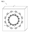
- FIG. 3 shows a section through a stator 11 with a drive ring 3 and a preparation vessel.
- the stator element 11 shown here surrounds the entire circumference of the preparation vessel M and the drive ring 3.
- the stator 11 consists here in the majority of a laminated core.
- Such a stator element 11 is particularly well suited for a reluctance drive.
- such a stator element 11 is suitable for a preparation vessel M, which has a vertically oriented direction of rotation and / or is variably alignable.
- the drive ring 3 also advantageously has a sheet metal package.
- the sheet-metal package also has recesses, wherein the recesses for receiving further drive magnets 7 are suitable (not shown).
- a reluctance drive retrofitted with magnets and the torque can be increased.
- the spatial fixation of the preparation vessel M and / or the drive ring is advantageously carried out with a roller bearing 21 (not shown), wherein the roller bearing 21 and / or a support 19 serves for a movable assignment of stator 11, 11 'and drive ring. Further functional relationships between the drive ring 3 and the stator element have already been described above.
- FIG. 4 shows a section through a part of a device (1) for the treatment of substances.
- the preparation vessel M is shown with a, attached to the preparation vessel drive ring 3, which extends between a comprehensive stator 11 or between two separate stator elements 11 '.
- a comprehensive stator element 11 is in FIG. 2 shown.
- Such a comprehensive stator element 11 is in plan view in FIG. 3 shown.
- the spatial fixation of the preparation vessel is carried out by rolling bearings 21.
- the rolling bearings 21 are associated with the stator element (s) 11, 11 'and serve to fix the preparation vessel M in its position and orientation and for low-friction rotational movement.
- the drive ring has in addition to the drive magnet 7 drive coils 7a, wherein the drive coils serve to generate a magnetic field and / or support the drive magnets.
- the power supply of the drive coil 7a is advantageous as solved in a DC motor, but the power transmission is not shown in this figure for the sake of clarity.
- the curved arrows indicate the direction of rotation of the preparation vessel M or the cylinder of the rolling bearing 21 in each case.
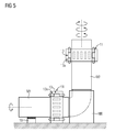
- FIG. 5 shows a device 1 for the treatment of substances with two treatment vessels M1, M2.
- the preparation vessels M1, M2 are connected by a connecting link MX.
- a link MX advantageously supports the transfer of substances from one treatment vessel M1 into the further treatment vessel M2 and / or vice versa.
- the connecting member MX support a fixation of the orientation and / or position of the at least one treatment vessel M1, M2.
- the connecting member MX can be used for positioning and securing the alignment of the further treatment vessel M2.
- the further preparation vessel M2 is aligned horizontally.
- the curved arrow symbolizes the direction of rotation of the further treatment vessel M.
- the further treatment vessel M2 can have a different direction of rotation and / or a different rotational speed during the treatment of the substances than the one preparation vessel M1. This is in the FIG. 5 symbolized by the two semicircular arrows.
- the one preparation vessel M1 with a support 19 is advantageously held in position and alignment.
- To generate the rotational movement of the preparation vessels M1, M2 serve stator elements 11, wherein the stator 11, the fixation possibly assist alignment and position, in particular by means of roller bearings 21 (not shown).
- the connecting member MX may also have a rotary operative connection between a plurality of treatment vessels M1, M2.
- uswiese serves a gear for carrying the rotational movement of a preparation vessel M1 to at least one further treatment vessel M2.
- FIG. 6 shows an alignable device for the treatment of substances.
- the treatment vessel M is fixed as a possibility only with the stator elements 11 '. Further holding devices are possible, but not shown.
- (an) inlet opening (s) for the at least one material to be treated or (an) outlet opening (s) for the at least one treated material are optionally present on the processing vessel, but not shown.
- the orientation of the preparation vessel is effected by an adjusting member 23a, which is connected via joints 23 to the stator elements 11 '. It is also possible, other stator elements 11, 11 'via a joint 23 with an adjusting 23a in height and / or in the position / orientation to make adjustable.
- the possibility of aligning the preparation vessel is symbolized by the curved double arrow.
- the rotational movement of the preparation vessel M is symbolized by the curved arrow on the axis of rotation.
- the control and / or regulation of the direction of rotation, the torque and / or the alignment takes place via the control device 25.
- the control device 25 is advantageously connected to a technical data connection 25a of the control of the system, in the preferred use of a paper machine.
- the arrow next to the adjusting member 23a symbolizes the adjustment of the adjusting member 23a.
- the control device 25 is advantageously connected to a valve, which adjusts the positioning / alignment of the joint 23 and / or the stator element 11 '.
- the control unit has a converter, so that the movement of the treatment vessel M can be controlled by a direct connection to the stator element 11 '.
- control device 25 may be connected to sensors (not shown for the sake of clarity), wherein the sensors assist in controlling the speed, torque, positioning and / or orientation of the treatment vessel M.
- the control device 25 can be supplemented with a control device.
- the invention relates to a device 1 and a method for the preparation of materials, in particular of raw materials in papermaking, preferably comprising a pulper or a dissolving drum, comprising a about a axis (rotation axis) rotatable treatment vessel M, M1, M2, wherein the processing vessel M , M1, M2 has at least one drive ring 3, wherein the drive ring 3 is fixedly connected to the preparation vessel M, M1, M2, wherein the drive ring 3 is provided in cooperation with at least one stator element 11, 11 'for rotating movement, wherein the stator element 11 , 11 'comprises electromagnets 13, the electromagnets 13 being provided for generating a torque of the preparation vessel M, M1, M2.
- the drive ring 3 has either drive magnets 7, in particular permanent magnets, or recesses 9. If the drive ring 3 has permanent magnets, the drive unit corresponds to a synchronous machine. If the drive ring 3 has recesses 9, the drive unit corresponds to a reluctance ring motor.
- the position and / or orientation of the treatment vessel M, M1, M2 is variable. Further advantageous are the drive-relevant variables such as torque, speed, position and / or orientation of the preparation vessel M, M1, M2 controllable or controllable by means of a control device 25.
Landscapes
- Engineering & Computer Science (AREA)
- Mechanical Engineering (AREA)
- Life Sciences & Earth Sciences (AREA)
- Wood Science & Technology (AREA)
- Paper (AREA)
- Manufacture Of Motors, Generators (AREA)
- Connection Of Motors, Electrical Generators, Mechanical Devices, And The Like (AREA)
- Dynamo-Electric Clutches, Dynamo-Electric Brakes (AREA)
Priority Applications (6)
| Application Number | Priority Date | Filing Date | Title |
|---|---|---|---|
| EP14166181.9A EP2940207A1 (fr) | 2014-04-28 | 2014-04-28 | Dispositif destiné à la préparation de substances |
| PCT/EP2015/056490 WO2015165659A1 (fr) | 2014-04-28 | 2015-03-26 | Dispositif de traitement de matières |
| ES15713685T ES3000667T3 (en) | 2014-04-28 | 2015-03-26 | Device for processing materials |
| FIEP15713685.4T FI3108057T3 (fi) | 2014-04-28 | 2015-03-26 | Laite aineiden käsittelyä varten |
| CN201580023354.0A CN106460324B (zh) | 2014-04-28 | 2015-03-26 | 用于处理材料的设备 |
| EP15713685.4A EP3108057B1 (fr) | 2014-04-28 | 2015-03-26 | Dispositif destiné à la préparation de substances |
Applications Claiming Priority (1)
| Application Number | Priority Date | Filing Date | Title |
|---|---|---|---|
| EP14166181.9A EP2940207A1 (fr) | 2014-04-28 | 2014-04-28 | Dispositif destiné à la préparation de substances |
Publications (1)
| Publication Number | Publication Date |
|---|---|
| EP2940207A1 true EP2940207A1 (fr) | 2015-11-04 |
Family
ID=50630603
Family Applications (2)
| Application Number | Title | Priority Date | Filing Date |
|---|---|---|---|
| EP14166181.9A Withdrawn EP2940207A1 (fr) | 2014-04-28 | 2014-04-28 | Dispositif destiné à la préparation de substances |
| EP15713685.4A Active EP3108057B1 (fr) | 2014-04-28 | 2015-03-26 | Dispositif destiné à la préparation de substances |
Family Applications After (1)
| Application Number | Title | Priority Date | Filing Date |
|---|---|---|---|
| EP15713685.4A Active EP3108057B1 (fr) | 2014-04-28 | 2015-03-26 | Dispositif destiné à la préparation de substances |
Country Status (5)
| Country | Link |
|---|---|
| EP (2) | EP2940207A1 (fr) |
| CN (1) | CN106460324B (fr) |
| ES (1) | ES3000667T3 (fr) |
| FI (1) | FI3108057T3 (fr) |
| WO (1) | WO2015165659A1 (fr) |
Families Citing this family (1)
| Publication number | Priority date | Publication date | Assignee | Title |
|---|---|---|---|---|
| CN111342092B (zh) * | 2020-02-15 | 2021-02-12 | 江苏大学 | 一种基于智能控制的车用燃料电池尾气处理装置及方法 |
Citations (4)
| Publication number | Priority date | Publication date | Assignee | Title |
|---|---|---|---|---|
| GB922500A (en) * | 1960-03-19 | 1963-04-03 | Erna Wandel | Improvements in or relating to apparatus for straining suspensions of solid particles |
| DE10319012A1 (de) * | 2003-04-28 | 2004-11-18 | Voith Paper Patent Gmbh | Drehteil mit Hohlwellenmotor und konzentrisch dazu angeordneter Drehlagerung |
| DE102009035247A1 (de) | 2009-07-29 | 2011-02-03 | Biotec Sistemi S.R.L. | Pulper mit Torque-Motor |
| DE102010043612A1 (de) * | 2009-11-10 | 2011-05-26 | Metso Paper, Inc. | Walzenantrieb, Walze und Verfahren |
Family Cites Families (1)
| Publication number | Priority date | Publication date | Assignee | Title |
|---|---|---|---|---|
| DE10252110A1 (de) * | 2002-11-08 | 2004-05-27 | Siemens Ag | Direktantrieb für einen Zylinder |
-
2014
- 2014-04-28 EP EP14166181.9A patent/EP2940207A1/fr not_active Withdrawn
-
2015
- 2015-03-26 EP EP15713685.4A patent/EP3108057B1/fr active Active
- 2015-03-26 ES ES15713685T patent/ES3000667T3/es active Active
- 2015-03-26 FI FIEP15713685.4T patent/FI3108057T3/fi active
- 2015-03-26 CN CN201580023354.0A patent/CN106460324B/zh active Active
- 2015-03-26 WO PCT/EP2015/056490 patent/WO2015165659A1/fr not_active Ceased
Patent Citations (4)
| Publication number | Priority date | Publication date | Assignee | Title |
|---|---|---|---|---|
| GB922500A (en) * | 1960-03-19 | 1963-04-03 | Erna Wandel | Improvements in or relating to apparatus for straining suspensions of solid particles |
| DE10319012A1 (de) * | 2003-04-28 | 2004-11-18 | Voith Paper Patent Gmbh | Drehteil mit Hohlwellenmotor und konzentrisch dazu angeordneter Drehlagerung |
| DE102009035247A1 (de) | 2009-07-29 | 2011-02-03 | Biotec Sistemi S.R.L. | Pulper mit Torque-Motor |
| DE102010043612A1 (de) * | 2009-11-10 | 2011-05-26 | Metso Paper, Inc. | Walzenantrieb, Walze und Verfahren |
Also Published As
| Publication number | Publication date |
|---|---|
| EP3108057A1 (fr) | 2016-12-28 |
| FI3108057T3 (fi) | 2024-11-27 |
| CN106460324B (zh) | 2019-01-18 |
| WO2015165659A1 (fr) | 2015-11-05 |
| CN106460324A (zh) | 2017-02-22 |
| EP3108057B1 (fr) | 2024-09-25 |
| ES3000667T3 (en) | 2025-03-03 |
Similar Documents
| Publication | Publication Date | Title |
|---|---|---|
| EP2828961B1 (fr) | Entraînement direct pour une machine tournante, en particulier, une machine de traitement de récipients | |
| EP2221272B1 (fr) | Dispositif de fermeture de récipients doté d'une production à couple sans contact | |
| EP3717132B1 (fr) | Séparateur | |
| DE2017311C3 (de) | Zentrifuge zum Trennen von Gasgemischen Und dazugehöriges Verfahren | |
| AT513498B1 (de) | Vorrichtung und Verfahren zur magnetischen Axiallagerung eines Rotors | |
| EP2737834A1 (fr) | Appareil électrique de traitement d'un produit alimentaire liquide ou d'un produit alimentaire à base de liquide, en particulier pour la formation de mousse dudit produit | |
| EP2950901B1 (fr) | Evaporateur rotatif | |
| DE112016000636T5 (de) | Schwingungsvorrichtung für Vibrationsverdichter | |
| EP4196284B1 (fr) | Insert de séparateur, séparateur, et procédé d'échange d'un insert de séparateur | |
| EP3930909B1 (fr) | Séparateur | |
| DE102006039090A1 (de) | Antrieb für Rotationsmaschinen | |
| DE102009018361B4 (de) | Anordnung zur Pitchwinkel-Verstellung mindestens eines Rotorblatts und Maschine, insbesondere Windkraftanlage | |
| EP4196282B1 (fr) | Insert de séparateur et séparateur | |
| EP2817526B1 (fr) | Palier magnétique avec compensation des forces | |
| EP3108057B1 (fr) | Dispositif destiné à la préparation de substances | |
| DE102009012353C5 (de) | Rollenmühle | |
| EP4196285B1 (fr) | Insert de séparateur et séparateur | |
| WO2015150411A1 (fr) | Accouplement magnétique, dispositif d'accouplement, et procédé correspondant | |
| EP3630628B1 (fr) | Machine de traitement de contenants et procédé de fonctionnement d'une machine de traitement de contenants | |
| DE2114040A1 (de) | Antrieb eines Rotors mit im wesentlichen vertikaler Drehachse | |
| DE102014210441A1 (de) | Drehgestell für einen Schienenfahrzeugwagen | |
| DE202013102392U1 (de) | Steuerungsanordnung für eine Synchronmaschine | |
| EP2801406A1 (fr) | Agencement pour un broyeur à rouleaux | |
| EP2955821A1 (fr) | Dispositif d'entraînement pour un élément rotatif | |
| DE102024101077A1 (de) | Schwungmassenspeicher |
Legal Events
| Date | Code | Title | Description |
|---|---|---|---|
| PUAI | Public reference made under article 153(3) epc to a published international application that has entered the european phase |
Free format text: ORIGINAL CODE: 0009012 |
|
| AK | Designated contracting states |
Kind code of ref document: A1 Designated state(s): AL AT BE BG CH CY CZ DE DK EE ES FI FR GB GR HR HU IE IS IT LI LT LU LV MC MK MT NL NO PL PT RO RS SE SI SK SM TR |
|
| AX | Request for extension of the european patent |
Extension state: BA ME |
|
| STAA | Information on the status of an ep patent application or granted ep patent |
Free format text: STATUS: THE APPLICATION IS DEEMED TO BE WITHDRAWN |
|
| 18D | Application deemed to be withdrawn |
Effective date: 20160505 |