EP2940228A1 - Dispositif de retenue destiné au support d'une ou plusieurs vitres en verre formant un appui de balustrade - Google Patents
Dispositif de retenue destiné au support d'une ou plusieurs vitres en verre formant un appui de balustrade Download PDFInfo
- Publication number
- EP2940228A1 EP2940228A1 EP14166530.7A EP14166530A EP2940228A1 EP 2940228 A1 EP2940228 A1 EP 2940228A1 EP 14166530 A EP14166530 A EP 14166530A EP 2940228 A1 EP2940228 A1 EP 2940228A1
- Authority
- EP
- European Patent Office
- Prior art keywords
- rail
- substructure
- holding device
- profile
- connecting rail
- Prior art date
- Legal status (The legal status is an assumption and is not a legal conclusion. Google has not performed a legal analysis and makes no representation as to the accuracy of the status listed.)
- Granted
Links
Images



Classifications
-
- E—FIXED CONSTRUCTIONS
- E04—BUILDING
- E04F—FINISHING WORK ON BUILDINGS, e.g. STAIRS, FLOORS
- E04F11/00—Stairways, ramps, or like structures; Balustrades; Handrails
- E04F11/18—Balustrades; Handrails
- E04F11/181—Balustrades
- E04F11/1812—Details of anchoring to the wall or floor
-
- E—FIXED CONSTRUCTIONS
- E04—BUILDING
- E04F—FINISHING WORK ON BUILDINGS, e.g. STAIRS, FLOORS
- E04F11/00—Stairways, ramps, or like structures; Balustrades; Handrails
- E04F11/18—Balustrades; Handrails
- E04F11/181—Balustrades
- E04F11/1851—Filling panels, e.g. concrete, sheet metal panels
- E04F11/1853—Glass panels
Definitions
- the invention relates to a holding device for supporting one or more a balustrade forming glass sheet according to the preamble of claim 1.
- a holding profile is fixed, to which the bag of the mounting rail is mounted during assembly of the balustrade parapet.
- the holding profile is therefore with a leg of the substructure and is freely accessible from above; the other leg is firmly attached to the substructure.
- the substructure by means of one or more Adjusting threaded pins is adjustable, is advantageously achieved that the vertical orientation of the balustrade parapet is independent of the contact surfaces between the mounting rail and the retaining profile vorrisebar exclusively from the regulatory threaded pin.
- the regulating threaded pin both as a distance adjusting aid and as a clamping and fastening screw, so that all the necessary fastening measures and the distance regulation can be ensured by the regulating threaded pin, or the regulatory threaded pin is spatially spaced to position a fastening and a clamping screw , by which the connecting rail is held in a position-oriented manner on the substructure or the retaining profile and by the clamping screw to the other a non-positive and positive operative connection between the connecting rail and the support rail is reached.
- the connecting rail can be moved relative to the support rail until the existing through holes are aligned with the mounting threaded hole and the threaded screws are positioned in the box profile of the connecting rail accordingly.
- the support rail By acting in particular in the horizontal direction compressive and tensile forces, which are absorbed by the regulating threaded pin and the fastening screw, the support rail can be arranged spatially spaced from the holding profile, so that there is no contact surface between this and the holding profile.
- the regulating threaded pins or the fixing screws define the distance between the mounting rail and the substructure by the predetermined unchangeable position, arises between the mounting rail and the substructure an air gap, so that advantageously support rail is spaced from the substructure or the holding profile. Consequently, the mounting rail requires no contact surface. Rather, the vertical adjustment of the mounting rail is accomplished exclusively by the positioning of the regulatory threaded pins or the mounting screw. It thus eliminates costly machining and assembly steps to achieve the orientation of the mounting rail in the mounted state in the desired vertical position.
- the entire holding device can be sealed by means of a sealing strip, so that water and air particles can be prevented from entering the substructure.
- the sealing strip also extends between the shoulder bag of the mounting rail and the perpendicular projecting from the substructure legs of the retaining profile and also between the mounting rail, the retaining profile or the substructure, so that the entire transition region between the components to be sealed, namely on the one hand, the substructure and the retaining profile and on the other hand, the support rail and the bag from each other are separated from each other air or waterproof.
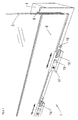
- FIG. 1 a holding device 1 is shown, which serves to support two a balustrade 2 forming glass sheets 3.
- the holding device 1 is attached to a substructure 4, such as a wall, a step or a ceiling or a floor and supports the balustrade parapet 2 from.
- the parapet parapet 2 should be kept in a position-oriented manner and be aligned in a straightforward manner.
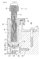
- FIG. 2 on the other hand, the assembled state of the holding device 1 on the substructure 4 and the vertical alignment of the parapet parapet 2 are shown.
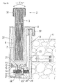
- FIGS. 3a . 3b and 3c refer to.
- the holding device 1 is formed from a U-shaped support rail 6, in which the two the balustrade 2 forming glass sheets 3 are used.
- the glass sheets 3 are connected to each other by means of films such that they form a safety glass, so that the balustrade parapet 2 is a fall protection, for example on stairs, parapets, balconies and the like.
- the glass sheets 3 are connected by means of an adhesive 7, for example, silicone-based, fixed to the inside of the support rail 6, so that the glass sheet 3 and the support rail 6 form a fixed assembly.
- the support rail 6 consequently surrounds the glass panes 3 in regions and supports them.
- the mounting rail 6 is firmly connected to the substructure 4 in such a way that the glass sheets 3 are aligned vertically.
- a U-shaped designed bag 1 is initially provided on the support rail 6, which is either integrally, as shown in the embodiment, connected to the support rail 6, or even releasably attached to the support rail 6, for example by means of screws or a weld, can be attached.
- the U-shaped designed shoulder bag 8 points in the direction of the substructure 4, to which a retaining profile 9 is fastened by means of a plurality of screws 33.
- a leg of the retaining profile 9 is therefore flat on the substructure 4, whereas the projecting perpendicularly projecting legs of the retaining profiles 9 protrudes in the direction of the shoulder bag 8, so that the support rail 6 can be placed with your bag 8 on the retaining profile 9 and therefore suspended.
- the hanging bag 8 essentially accommodates the vertical downward weight forces of the balustrade 2.
- the horizontal distance between the support rail 6 of the bag 8 on the one hand and the vertically projecting leg of the holding profile 9 on the other hand is sized so large that on the one hand the bag 8 can be hung almost free of play on the leg of the support section 9 and on the other the horizontal forces and Nevertheless, torques from the bag 8 are supported and are forwarded to the vertically projecting leg of the holding profile 9.
- a rail guide 12 is integrally formed on the underside 11 of the support rail 6, which is thus firmly connected to the support rail 6.
- the rail guide 12 consists of two extending in a plane and projecting lugs 13 are formed by the two mutually parallel rails or undercuts.
- the rail guide 12 accordingly has an I-shape in the cross-sectional profile.
- connection rail 14 may also be clipped onto the guide rail 12 in order to achieve a locking of the connecting rail 14 to the support rail 6.
- the inner contour 15 of the connecting rail 14 is adapted to the outer contour of the rail guide 12 and thus consists of a partially open U-profile cross-section.
- the two facing each other noses of the connecting rail 14 extend in the inserted state of the connecting rail 14 on the inside of the rail guide 12 and are encompassed and supported by the two protruding lugs 13 and the substantially horizontally extending bottom 11 of the support rail 6.
- connection between the mounting rail 6 and the connecting rail 14 is a dovetail guide, which allows a relative movement between the connecting rail 14 and the mounting rail 6 in the preassembled state.
- the connecting rail 14 can be moved in the direction of the longitudinal axis 5 of the balustrade parapet 2 until the through-holes 27 incorporated in the connecting rail 14 are positioned in alignment with a threaded hole or nut to be described in greater detail below, in order to position the connecting rail 14 and thus the support rail 6 perpendicular to the substructure 4 to position.
- a fastening screw 18 is provided, which passes through an incorporated into the connecting rail 14 through opening 27 and projects in the direction of the substructure 4.
- a threaded bore 26 is incorporated, so that the passage opening 27 of the connecting rail 14 and the threaded bore 26 of the substructure 4 for mounting the connecting rail 14 on the substructure 4 must be in alignment with each other.
- the connecting rail 14 can therefore be moved along the longitudinal axis 5 of the balustrade parapet 2 until the threaded bore 26 is aligned with the passage opening 27 of the connecting rail 14.
- the head of the fastening screw 18 rests against a limb projecting from the connecting rail 14, so that when the fastening screw 18 is screwed in in the direction of the substructure 4, the connecting rail 14 is pressed in the direction of the substructure 4.
- this attraction by the fastening screw 18 would cause the balustrade 2 tilts to the left and that the parapet parapet 2 is not sufficiently secured to be pushed further to the left, for example, parallel to the substructure 4 on the free end of the balustrade corresponding horizontal forces act.
- One of the railing parapet 2 final handrail 31 thus moves to the bearing axis defined by the mounting screw 18 by up to 20 millimeters from the vertical.
- a regulating threaded pin 17 is provided, which is inserted into a further passage opening 27 of the connecting rail 14 and this according to FIG. 3b be upheld.
- the free end of the regulating threaded pin 17 abuts against the end face of the substructure 4 facing the support rail 6 or else on the retaining profile 19, so that the regulating threaded pin 17 is supported by the substructure 4 to the right.
- a mechanical connection between the regulating threaded pin 17 and the connecting rail 14 is achieved in that a box section 28 is formed or worked on this, in which a threaded nut 29 is laterally inserted.
- the box section 28 has a further passage opening 27 which extends in alignment with the threaded bore 26 so that the regulating threaded pin 17 is movable through the box section 28 in the direction of the substructure 4 until the regulating threaded pin 17 bears against the substructure 4 and thus the connecting rail 14 and thus also the support rail 6 in the horizontal direction and in the direction of the substructure 4 is supported.
- the regulating threaded pin 17 fixes the connecting rail 14 in the horizontal direction with the substructure 4.
- the vertical orientation of the parapet parapet 2 can be adjusted so that an exact desired vertical position of the parapet parapet 2 is reached.
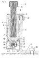
- FIG 3c is shown how the non-positive and positive operative connection between the connecting bar 14 and the rail guide 12 of the support rail 6 is reached.
- a further threaded nut 29 is inserted into the box section 28 of the connecting rail 14, which is to be positioned in alignment with a further passage opening 24.
- a clamping screw 19 is screwed, the head rests on the outside of the connecting rail 14.
- FIGS. 4 and 5 These three spatially separated fastening and adjusting means can also be combined in a single regulating threaded pin 17.
- FIG. 5 It can be seen that the regulating threaded pin 17 has a plurality of spatially separated areas, each of which assumes the function that in the FIGS. 3a . 3b and 3c are explained.
- a sealing tape 20 is provided, through which the entire parting plane between the holding device 1 and the substructure 4 is sealed. Accordingly, the sealing edge 20 extends between the connecting rail 14, the mounting rail 6, the shoulder bag 8 and the substructure 4 and seals them against incoming water particles.
- the regulating threaded pin 17 passes through a recess incorporated in the sealing strip 20 and presses the sealing strip 14 against the substructure 4.
- the mounting of the mounting rail 6 and the connecting rail 14 is carried out such that the regulating threaded pin 17 is first pushed through the incorporated into the connecting rail 14 through holes 24 and 27 and screwed into the substructure 4 threaded bore 26 is screwed.
- the sealing edge 20 is penetrated by this and pressed firmly by means of a screwed onto the Einstelltechniksschraube 17 threaded nut 29 to the substructure, whereby the regulating threaded pin 17 is fixedly positioned on the substructure 4.
- the threaded nut 29 inserted into the box section 28 and the threaded nut 29 through which the As soon as the distance between these two threaded nuts 29 is reduced or increased, the balustrade parachute 2 moves about the vertical axis.
- the two exemplary embodiments have in common that the vertical alignment of the balustrade parapet 2 is achieved by means of a bearing rail 21 integrally formed on the underside 11 of the support rail 6.
- the free end of the bearing rail 21 has an approximately spherical head 22 on which rests the respective regulating pins 17, the fastening screw 18 and the clamping screw 19, which either have an outer circumferential surface or the thread structure which is flat in this area.
- a correspondingly sized through-groove 25 is incorporated in this, which is penetrated by the bearing rail 21 and the head 22 ..
Landscapes
- Engineering & Computer Science (AREA)
- Architecture (AREA)
- Civil Engineering (AREA)
- Structural Engineering (AREA)
- Bridges Or Land Bridges (AREA)
Priority Applications (1)
| Application Number | Priority Date | Filing Date | Title |
|---|---|---|---|
| EP14166530.7A EP2940228B1 (fr) | 2014-04-30 | 2014-04-30 | Dispositif de retenue destiné au support d'une ou plusieurs vitres en verre formant un appui de balustrade |
Applications Claiming Priority (1)
| Application Number | Priority Date | Filing Date | Title |
|---|---|---|---|
| EP14166530.7A EP2940228B1 (fr) | 2014-04-30 | 2014-04-30 | Dispositif de retenue destiné au support d'une ou plusieurs vitres en verre formant un appui de balustrade |
Publications (2)
| Publication Number | Publication Date |
|---|---|
| EP2940228A1 true EP2940228A1 (fr) | 2015-11-04 |
| EP2940228B1 EP2940228B1 (fr) | 2018-02-14 |
Family
ID=50628647
Family Applications (1)
| Application Number | Title | Priority Date | Filing Date |
|---|---|---|---|
| EP14166530.7A Active EP2940228B1 (fr) | 2014-04-30 | 2014-04-30 | Dispositif de retenue destiné au support d'une ou plusieurs vitres en verre formant un appui de balustrade |
Country Status (1)
| Country | Link |
|---|---|
| EP (1) | EP2940228B1 (fr) |
Cited By (8)
| Publication number | Priority date | Publication date | Assignee | Title |
|---|---|---|---|---|
| US20150007514A1 (en) * | 2004-07-15 | 2015-01-08 | Abdul Lathief | Self-locking handrail system |
| CN106088494A (zh) * | 2016-07-28 | 2016-11-09 | 苏州金螳螂建筑装饰股份有限公司 | 小半径旋转楼梯玻璃扶手安装结构 |
| GB2566303A (en) * | 2017-09-08 | 2019-03-13 | Fastec Handrail Systems Ltd | Panel support |
| CN113323301A (zh) * | 2021-05-08 | 2021-08-31 | 中国建筑第八工程局有限公司 | 挑空楼板的异型外倾玻璃栏杆构造 |
| AT523545B1 (de) * | 2020-06-15 | 2021-09-15 | Weiss Rupert | Verstellbarer punkthalter |
| FR3111653A1 (fr) * | 2020-06-23 | 2021-12-24 | Speedinnov | Dispositif pour la formation d’une balustrade dans un véhicule, notamment ferroviaire |
| EP3974598A1 (fr) * | 2020-09-23 | 2022-03-30 | Ebner event logistics GmbH | Module de garde-corps |
| CN117052068A (zh) * | 2023-09-05 | 2023-11-14 | 中建科工集团有限公司 | 夹持玻璃的楼梯栏杆构造及其施工方法 |
Families Citing this family (1)
| Publication number | Priority date | Publication date | Assignee | Title |
|---|---|---|---|---|
| US20240076878A1 (en) * | 2022-09-07 | 2024-03-07 | Bendheim Wall Systems Inc. | Fascia Rail System |
Citations (3)
| Publication number | Priority date | Publication date | Assignee | Title |
|---|---|---|---|---|
| DE10338816B3 (de) * | 2003-08-21 | 2005-05-25 | Bernhard Feigl | Halterung für eine Platte, insbesondere für eine Glasscheibe |
| DE102006028766A1 (de) * | 2006-06-23 | 2007-12-27 | Bernhard Feigl | Haltevorrichtung für eine Platte |
| EP2194207B1 (fr) | 2008-12-05 | 2012-12-05 | Bernhard Feigl | Dispositif de support du panneau en verre d'un garde-corps |
-
2014
- 2014-04-30 EP EP14166530.7A patent/EP2940228B1/fr active Active
Patent Citations (3)
| Publication number | Priority date | Publication date | Assignee | Title |
|---|---|---|---|---|
| DE10338816B3 (de) * | 2003-08-21 | 2005-05-25 | Bernhard Feigl | Halterung für eine Platte, insbesondere für eine Glasscheibe |
| DE102006028766A1 (de) * | 2006-06-23 | 2007-12-27 | Bernhard Feigl | Haltevorrichtung für eine Platte |
| EP2194207B1 (fr) | 2008-12-05 | 2012-12-05 | Bernhard Feigl | Dispositif de support du panneau en verre d'un garde-corps |
Cited By (11)
| Publication number | Priority date | Publication date | Assignee | Title |
|---|---|---|---|---|
| US20150007514A1 (en) * | 2004-07-15 | 2015-01-08 | Abdul Lathief | Self-locking handrail system |
| US9797185B2 (en) * | 2004-07-15 | 2017-10-24 | City Glass & Glazing (P) Ltd. | Self-locking handrail system |
| CN106088494A (zh) * | 2016-07-28 | 2016-11-09 | 苏州金螳螂建筑装饰股份有限公司 | 小半径旋转楼梯玻璃扶手安装结构 |
| CN106088494B (zh) * | 2016-07-28 | 2018-07-10 | 苏州金螳螂建筑装饰股份有限公司 | 小半径旋转楼梯玻璃扶手安装结构 |
| GB2566303A (en) * | 2017-09-08 | 2019-03-13 | Fastec Handrail Systems Ltd | Panel support |
| AT523545B1 (de) * | 2020-06-15 | 2021-09-15 | Weiss Rupert | Verstellbarer punkthalter |
| AT523545A4 (de) * | 2020-06-15 | 2021-09-15 | Weiss Rupert | Verstellbarer punkthalter |
| FR3111653A1 (fr) * | 2020-06-23 | 2021-12-24 | Speedinnov | Dispositif pour la formation d’une balustrade dans un véhicule, notamment ferroviaire |
| EP3974598A1 (fr) * | 2020-09-23 | 2022-03-30 | Ebner event logistics GmbH | Module de garde-corps |
| CN113323301A (zh) * | 2021-05-08 | 2021-08-31 | 中国建筑第八工程局有限公司 | 挑空楼板的异型外倾玻璃栏杆构造 |
| CN117052068A (zh) * | 2023-09-05 | 2023-11-14 | 中建科工集团有限公司 | 夹持玻璃的楼梯栏杆构造及其施工方法 |
Also Published As
| Publication number | Publication date |
|---|---|
| EP2940228B1 (fr) | 2018-02-14 |
Similar Documents
| Publication | Publication Date | Title |
|---|---|---|
| EP2940228B1 (fr) | Dispositif de retenue destiné au support d'une ou plusieurs vitres en verre formant un appui de balustrade | |
| DE10338816B3 (de) | Halterung für eine Platte, insbesondere für eine Glasscheibe | |
| DE69705662T2 (de) | Rollvorrichtung für Schiebetüren, Fenster oder ähnliches | |
| DE69125572T2 (de) | Tragschiene für eine gläserne Tür oder Trennwand | |
| CH627508A5 (de) | Verschiebbare wand mit boden- und deckendichtung. | |
| EP0056564A2 (fr) | Ensemble de porte coulissante | |
| EP3594427B1 (fr) | Système et procédé de fixation d'éléments de façade | |
| EP2235279A2 (fr) | Dispositif d'accrochage pour une façade et façade | |
| EP2194207B1 (fr) | Dispositif de support du panneau en verre d'un garde-corps | |
| EP2365155A1 (fr) | Dispositif de fixation d'un appui de balustrade | |
| AT511046B1 (de) | Rahmensystem eines partikelschutzgitters | |
| DE69306287T2 (de) | Verstellbarer Laufwagen für Schiebetür- und Schiebefensterbeschläge | |
| DE29621112U1 (de) | Fliegenschutzgitter | |
| EP4114777A1 (fr) | Dispositif de protection lors de travaux d'installation sur un escalier roulant ou un trottoir roulant | |
| DE69600926T2 (de) | Gitterträger für tragende geländer von hängebühne | |
| DE3527224C3 (de) | Befestigungsvorrichtung für eine Fassadenverkleidung | |
| EP2700778A1 (fr) | Dispositif de soutien déplaçable d'une plaque | |
| EP2935742A1 (fr) | Système de porte | |
| EP1500768A2 (fr) | Dispositif de support et de fixation d'encadrements pour portes ou fenêtres à la périphérie d'une ouverture de paroi | |
| DE2611323A1 (de) | Einstellvorrichtung | |
| EP1126099A2 (fr) | Dispositif de fixation pour éléments de façade en plaques | |
| EP3293336B1 (fr) | Rail de retenue pour un balcon français ainsi que dispositif et système de retenue associés | |
| EP1485563A1 (fr) | Dispositif de support et de guidage permettant de fixer des elements porte ou mur mobiles suspendus | |
| DE4140867A1 (de) | Fassadenkonstruktion | |
| EP3098361A1 (fr) | Construction plane destinée à la réalisation de parois, parois de séparation, façades et similaires |
Legal Events
| Date | Code | Title | Description |
|---|---|---|---|
| PUAI | Public reference made under article 153(3) epc to a published international application that has entered the european phase |
Free format text: ORIGINAL CODE: 0009012 |
|
| 17P | Request for examination filed |
Effective date: 20150318 |
|
| AK | Designated contracting states |
Kind code of ref document: A1 Designated state(s): AL AT BE BG CH CY CZ DE DK EE ES FI FR GB GR HR HU IE IS IT LI LT LU LV MC MK MT NL NO PL PT RO RS SE SI SK SM TR |
|
| AX | Request for extension of the european patent |
Extension state: BA ME |
|
| GRAJ | Information related to disapproval of communication of intention to grant by the applicant or resumption of examination proceedings by the epo deleted |
Free format text: ORIGINAL CODE: EPIDOSDIGR1 |
|
| GRAP | Despatch of communication of intention to grant a patent |
Free format text: ORIGINAL CODE: EPIDOSNIGR1 |
|
| INTG | Intention to grant announced |
Effective date: 20171031 |
|
| GRAS | Grant fee paid |
Free format text: ORIGINAL CODE: EPIDOSNIGR3 |
|
| GRAA | (expected) grant |
Free format text: ORIGINAL CODE: 0009210 |
|
| AK | Designated contracting states |
Kind code of ref document: B1 Designated state(s): AL AT BE BG CH CY CZ DE DK EE ES FI FR GB GR HR HU IE IS IT LI LT LU LV MC MK MT NL NO PL PT RO RS SE SI SK SM TR |
|
| REG | Reference to a national code |
Ref country code: GB Ref legal event code: FG4D Free format text: NOT ENGLISH |
|
| REG | Reference to a national code |
Ref country code: CH Ref legal event code: EP |
|
| REG | Reference to a national code |
Ref country code: IE Ref legal event code: FG4D Free format text: LANGUAGE OF EP DOCUMENT: GERMAN |
|
| REG | Reference to a national code |
Ref country code: DE Ref legal event code: R096 Ref document number: 502014007228 Country of ref document: DE Ref country code: AT Ref legal event code: REF Ref document number: 969927 Country of ref document: AT Kind code of ref document: T Effective date: 20180315 |
|
| REG | Reference to a national code |
Ref country code: NL Ref legal event code: MP Effective date: 20180214 |
|
| PG25 | Lapsed in a contracting state [announced via postgrant information from national office to epo] |
Ref country code: ES Free format text: LAPSE BECAUSE OF FAILURE TO SUBMIT A TRANSLATION OF THE DESCRIPTION OR TO PAY THE FEE WITHIN THE PRESCRIBED TIME-LIMIT Effective date: 20180214 Ref country code: NO Free format text: LAPSE BECAUSE OF FAILURE TO SUBMIT A TRANSLATION OF THE DESCRIPTION OR TO PAY THE FEE WITHIN THE PRESCRIBED TIME-LIMIT Effective date: 20180514 Ref country code: HR Free format text: LAPSE BECAUSE OF FAILURE TO SUBMIT A TRANSLATION OF THE DESCRIPTION OR TO PAY THE FEE WITHIN THE PRESCRIBED TIME-LIMIT Effective date: 20180214 Ref country code: LT Free format text: LAPSE BECAUSE OF FAILURE TO SUBMIT A TRANSLATION OF THE DESCRIPTION OR TO PAY THE FEE WITHIN THE PRESCRIBED TIME-LIMIT Effective date: 20180214 Ref country code: CY Free format text: LAPSE BECAUSE OF FAILURE TO SUBMIT A TRANSLATION OF THE DESCRIPTION OR TO PAY THE FEE WITHIN THE PRESCRIBED TIME-LIMIT Effective date: 20180214 Ref country code: NL Free format text: LAPSE BECAUSE OF FAILURE TO SUBMIT A TRANSLATION OF THE DESCRIPTION OR TO PAY THE FEE WITHIN THE PRESCRIBED TIME-LIMIT Effective date: 20180214 Ref country code: FI Free format text: LAPSE BECAUSE OF FAILURE TO SUBMIT A TRANSLATION OF THE DESCRIPTION OR TO PAY THE FEE WITHIN THE PRESCRIBED TIME-LIMIT Effective date: 20180214 |
|
| PG25 | Lapsed in a contracting state [announced via postgrant information from national office to epo] |
Ref country code: GR Free format text: LAPSE BECAUSE OF FAILURE TO SUBMIT A TRANSLATION OF THE DESCRIPTION OR TO PAY THE FEE WITHIN THE PRESCRIBED TIME-LIMIT Effective date: 20180515 Ref country code: LV Free format text: LAPSE BECAUSE OF FAILURE TO SUBMIT A TRANSLATION OF THE DESCRIPTION OR TO PAY THE FEE WITHIN THE PRESCRIBED TIME-LIMIT Effective date: 20180214 Ref country code: RS Free format text: LAPSE BECAUSE OF FAILURE TO SUBMIT A TRANSLATION OF THE DESCRIPTION OR TO PAY THE FEE WITHIN THE PRESCRIBED TIME-LIMIT Effective date: 20180214 Ref country code: SE Free format text: LAPSE BECAUSE OF FAILURE TO SUBMIT A TRANSLATION OF THE DESCRIPTION OR TO PAY THE FEE WITHIN THE PRESCRIBED TIME-LIMIT Effective date: 20180214 Ref country code: BG Free format text: LAPSE BECAUSE OF FAILURE TO SUBMIT A TRANSLATION OF THE DESCRIPTION OR TO PAY THE FEE WITHIN THE PRESCRIBED TIME-LIMIT Effective date: 20180514 |
|
| PG25 | Lapsed in a contracting state [announced via postgrant information from national office to epo] |
Ref country code: MT Free format text: LAPSE BECAUSE OF FAILURE TO SUBMIT A TRANSLATION OF THE DESCRIPTION OR TO PAY THE FEE WITHIN THE PRESCRIBED TIME-LIMIT Effective date: 20180214 |
|
| PG25 | Lapsed in a contracting state [announced via postgrant information from national office to epo] |
Ref country code: PL Free format text: LAPSE BECAUSE OF FAILURE TO SUBMIT A TRANSLATION OF THE DESCRIPTION OR TO PAY THE FEE WITHIN THE PRESCRIBED TIME-LIMIT Effective date: 20180214 Ref country code: IT Free format text: LAPSE BECAUSE OF FAILURE TO SUBMIT A TRANSLATION OF THE DESCRIPTION OR TO PAY THE FEE WITHIN THE PRESCRIBED TIME-LIMIT Effective date: 20180214 Ref country code: EE Free format text: LAPSE BECAUSE OF FAILURE TO SUBMIT A TRANSLATION OF THE DESCRIPTION OR TO PAY THE FEE WITHIN THE PRESCRIBED TIME-LIMIT Effective date: 20180214 Ref country code: AL Free format text: LAPSE BECAUSE OF FAILURE TO SUBMIT A TRANSLATION OF THE DESCRIPTION OR TO PAY THE FEE WITHIN THE PRESCRIBED TIME-LIMIT Effective date: 20180214 Ref country code: RO Free format text: LAPSE BECAUSE OF FAILURE TO SUBMIT A TRANSLATION OF THE DESCRIPTION OR TO PAY THE FEE WITHIN THE PRESCRIBED TIME-LIMIT Effective date: 20180214 |
|
| REG | Reference to a national code |
Ref country code: DE Ref legal event code: R097 Ref document number: 502014007228 Country of ref document: DE |
|
| PG25 | Lapsed in a contracting state [announced via postgrant information from national office to epo] |
Ref country code: MC Free format text: LAPSE BECAUSE OF FAILURE TO SUBMIT A TRANSLATION OF THE DESCRIPTION OR TO PAY THE FEE WITHIN THE PRESCRIBED TIME-LIMIT Effective date: 20180214 Ref country code: CZ Free format text: LAPSE BECAUSE OF FAILURE TO SUBMIT A TRANSLATION OF THE DESCRIPTION OR TO PAY THE FEE WITHIN THE PRESCRIBED TIME-LIMIT Effective date: 20180214 Ref country code: SK Free format text: LAPSE BECAUSE OF FAILURE TO SUBMIT A TRANSLATION OF THE DESCRIPTION OR TO PAY THE FEE WITHIN THE PRESCRIBED TIME-LIMIT Effective date: 20180214 Ref country code: SM Free format text: LAPSE BECAUSE OF FAILURE TO SUBMIT A TRANSLATION OF THE DESCRIPTION OR TO PAY THE FEE WITHIN THE PRESCRIBED TIME-LIMIT Effective date: 20180214 Ref country code: DK Free format text: LAPSE BECAUSE OF FAILURE TO SUBMIT A TRANSLATION OF THE DESCRIPTION OR TO PAY THE FEE WITHIN THE PRESCRIBED TIME-LIMIT Effective date: 20180214 |
|
| REG | Reference to a national code |
Ref country code: BE Ref legal event code: MM Effective date: 20180430 |
|
| PLBE | No opposition filed within time limit |
Free format text: ORIGINAL CODE: 0009261 |
|
| STAA | Information on the status of an ep patent application or granted ep patent |
Free format text: STATUS: NO OPPOSITION FILED WITHIN TIME LIMIT |
|
| 26N | No opposition filed |
Effective date: 20181115 |
|
| REG | Reference to a national code |
Ref country code: IE Ref legal event code: MM4A |
|
| GBPC | Gb: european patent ceased through non-payment of renewal fee |
Effective date: 20180514 |
|
| PG25 | Lapsed in a contracting state [announced via postgrant information from national office to epo] |
Ref country code: LU Free format text: LAPSE BECAUSE OF NON-PAYMENT OF DUE FEES Effective date: 20180430 |
|
| PG25 | Lapsed in a contracting state [announced via postgrant information from national office to epo] |
Ref country code: BE Free format text: LAPSE BECAUSE OF NON-PAYMENT OF DUE FEES Effective date: 20180430 Ref country code: SI Free format text: LAPSE BECAUSE OF FAILURE TO SUBMIT A TRANSLATION OF THE DESCRIPTION OR TO PAY THE FEE WITHIN THE PRESCRIBED TIME-LIMIT Effective date: 20180214 |
|
| PG25 | Lapsed in a contracting state [announced via postgrant information from national office to epo] |
Ref country code: IE Free format text: LAPSE BECAUSE OF NON-PAYMENT OF DUE FEES Effective date: 20180430 Ref country code: GB Free format text: LAPSE BECAUSE OF NON-PAYMENT OF DUE FEES Effective date: 20180514 Ref country code: FR Free format text: LAPSE BECAUSE OF NON-PAYMENT OF DUE FEES Effective date: 20180430 |
|
| PG25 | Lapsed in a contracting state [announced via postgrant information from national office to epo] |
Ref country code: TR Free format text: LAPSE BECAUSE OF FAILURE TO SUBMIT A TRANSLATION OF THE DESCRIPTION OR TO PAY THE FEE WITHIN THE PRESCRIBED TIME-LIMIT Effective date: 20180214 |
|
| PG25 | Lapsed in a contracting state [announced via postgrant information from national office to epo] |
Ref country code: PT Free format text: LAPSE BECAUSE OF FAILURE TO SUBMIT A TRANSLATION OF THE DESCRIPTION OR TO PAY THE FEE WITHIN THE PRESCRIBED TIME-LIMIT Effective date: 20180214 |
|
| PG25 | Lapsed in a contracting state [announced via postgrant information from national office to epo] |
Ref country code: MK Free format text: LAPSE BECAUSE OF NON-PAYMENT OF DUE FEES Effective date: 20180214 Ref country code: HU Free format text: LAPSE BECAUSE OF FAILURE TO SUBMIT A TRANSLATION OF THE DESCRIPTION OR TO PAY THE FEE WITHIN THE PRESCRIBED TIME-LIMIT; INVALID AB INITIO Effective date: 20140430 |
|
| PG25 | Lapsed in a contracting state [announced via postgrant information from national office to epo] |
Ref country code: IS Free format text: LAPSE BECAUSE OF FAILURE TO SUBMIT A TRANSLATION OF THE DESCRIPTION OR TO PAY THE FEE WITHIN THE PRESCRIBED TIME-LIMIT Effective date: 20180614 |
|
| REG | Reference to a national code |
Ref country code: DE Ref legal event code: R082 Ref document number: 502014007228 Country of ref document: DE Representative=s name: GEITZ PATENTANWAELTE PARTG MBB, DE Ref country code: DE Ref legal event code: R082 Ref document number: 502014007228 Country of ref document: DE Representative=s name: GEITZ TRUCKENMUELLER LUCHT CHRIST PATENTANWAEL, DE |
|
| P01 | Opt-out of the competence of the unified patent court (upc) registered |
Effective date: 20230512 |
|
| PGFP | Annual fee paid to national office [announced via postgrant information from national office to epo] |
Ref country code: DE Payment date: 20250417 Year of fee payment: 12 |
|
| PGFP | Annual fee paid to national office [announced via postgrant information from national office to epo] |
Ref country code: CH Payment date: 20250501 Year of fee payment: 12 |
|
| PGFP | Annual fee paid to national office [announced via postgrant information from national office to epo] |
Ref country code: AT Payment date: 20250416 Year of fee payment: 12 |