EP2194207B1 - Dispositif de support du panneau en verre d'un garde-corps - Google Patents
Dispositif de support du panneau en verre d'un garde-corps Download PDFInfo
- Publication number
- EP2194207B1 EP2194207B1 EP08021182A EP08021182A EP2194207B1 EP 2194207 B1 EP2194207 B1 EP 2194207B1 EP 08021182 A EP08021182 A EP 08021182A EP 08021182 A EP08021182 A EP 08021182A EP 2194207 B1 EP2194207 B1 EP 2194207B1
- Authority
- EP
- European Patent Office
- Prior art keywords
- rail
- holding
- holding device
- box
- accordance
- Prior art date
- Legal status (The legal status is an assumption and is not a legal conclusion. Google has not performed a legal analysis and makes no representation as to the accuracy of the status listed.)
- Active
Links
Images





Classifications
-
- E—FIXED CONSTRUCTIONS
- E04—BUILDING
- E04F—FINISHING WORK ON BUILDINGS, e.g. STAIRS, FLOORS
- E04F11/00—Stairways, ramps, or like structures; Balustrades; Handrails
- E04F11/18—Balustrades; Handrails
- E04F11/181—Balustrades
- E04F11/1851—Filling panels, e.g. concrete, sheet metal panels
Definitions
- the invention relates to a holding device, by which one or more a balustrade forming glass sheets is supported on a wall or ceiling according to the preamble of claim 1.
- Such fixtures have been developed by the Applicant in the recent past; For example, such a holding device from the DE 103 38 816 B3 be removed.
- the glass panes forming the balustrade are inserted in a U-profile rail and are fixed there by means of an adhesive and spacers.
- a U-shaped designed shoulder bag is formed, which is hooked into a nose, which is integrally formed on a base profile.
- the basic profile is fixed to the ceiling and extends over the entire length of the parapet parapet.
- the bag and the molded on the base profile retaining lug take as a floating bearing horizontally acting forces, especially between the horizontally extending leg of the bag and the free end of the retaining lug in the assembled state, an air gap is provided.
- the vertical weight forces caused by the railing parapet that is to say the glass panes, are supported on the underside of the support rail by the base profile, because there is provided a detent designed as a fixed bearing, by which the U-profile rail is supported in the vertical and horizontal directions.
- the adjusting screws pass through a fixing plate, which is positively connected to the underside of the U-profile rail.
- a fixing plate which is positively connected to the underside of the U-profile rail.
- the basic profile has a complicated structural design. Namely, the basic profile is to be manufactured, for example, as an extruded profile in order to provide a contact surface extending over the entire length of the parapet parapet for the U-profile rail. In some buildings and applications, however, has been found that the structurally complex design of the basic profile after the DE 103 38 818 B3 not absolutely necessary.
- a clamping screw is provided, which is screwed to a in the box rail and a frictionally held in this nut and the other by means of the integrally formed on the clamping screw head on the outside of the support rail. Consequently, the support rail is supported by means of adjusting and clamping screws on the box rail;
- a strip or individual holding blocks can be molded to the upwardly projecting end face of the retaining plate to the building construction of the building to adapt the suspension of the support rail to the support plate to these circumstances.
- FIG. 1 is a holding device 1zu refer, is supported by a constructed of two sheets of glass 2 parapet railing 3 between two walls 4 on a ceiling 5.
- the selected representation is a schematic illustration for such balustrade parapets 3.
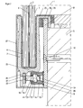
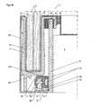
- the structural design of the holding device 1 and the different design variants and applications are shown in FIGS. 2 to 7. Identical components are provided with identical reference numbers.
- the holding device 1 consists of a U-shaped support rail 7, in which the two glass sheets 2 are inserted.
- the support rail 7 may also be designed as a L-shaped receiving body or as a plate.
- the two glass sheets 2 are firmly connected to one another via an adhesive film 6 arranged between them, so that a safety glass is produced.
- the safety glass so at least one of the two glass panes 2, is fixedly connected to the support rail 7, for example via an adhesive 8.
- mechanical connections for example by means of fastening screws, which pass through the glass sheets 2 and are supported on the support rail 7, can be used for the provision of a parapet parapet 3.
- the fixation of the two glass panes 2 with the support rail 7 takes place at the factory, so that they are delivered pre-assembled as a unit.
- a holding plate 9 made of metal by means of fastening screws 10 is attached.
- the holding plate 9 projects beyond the bottom formed by the ceiling 5, so that the free end 9 'of the holding plate 9, which protrudes from the ceiling 5, can be used as a retaining lug or retaining web for a molded onto the mounting rail 7 shoulder bag 25.
- the U-shaped designed shoulder bag 25, which is integrally formed on a support plate facing leg of the support rail 7, is used exclusively to support in the assembled state, the horizontally acting forces on the support plate 9 in the form of a floating bearing.
- an air gap 30 is provided between the horizontally extending leg of the shoulder bag 25 and the free end face of the holding plate 9.
- the balancing body 26 may be made of metal or of a hard material, such as plastic.
- the distance in the horizontal direction between the two inner surfaces of the shoulder bag 25 and the two outer surfaces of the support plate 9 can be compensated by the Ausreteskörpem 26; Namely, the width of the holding plate 9 may vary or have waves over its length.
- Such a compensatory measure causes the support rail 7 is tilted, that is inclined from the vertical in the direction of the support plate 9 and is applied to this linear.
- this pre-assembly condition is not desired for the parapet parapet 3; rather, the parapet parapet 3 should run vertically, ie exactly vertically.
- a box rail 11 is provided in the lower region of the support rail 7, which via a support member 12, which in the illustrated embodiment of Figures 2 and 3 is formed as a box-shaped rail 14 is fixed to the holding plate 9.
- the rail 14 is secured by means of two opposing and mutually parallel welds 15 on the support plate 9 and is perpendicular from this.
- the top of the rail 14 forms a support surface 23 on which the underside of the support rail 7 flies in the mounted state and is thus supported in the vertical direction.
- a set screw 16 and a clamping screw 34 is used, which run perpendicular to the holding plate 9 and the head 16 'and 34' non-positively or positively connected to the support rail 7, as will be explained in more detail below are.
- the adjusting screw 16 engages through a slot-like or round opening 22 incorporated in the rail 14 and two through bores 18 and 19 incorporated in the box rail 11.
- the opening 22 and the two through bores 18 and 19 therefore run in alignment with one another in the mounted state.
- a rectangular recess 20 is incorporated into the interior of the box rail 11, into which a nut 21 is inserted, so that the threaded bore of the nut 21 is aligned with the opening 22 and the two through holes 18 and 19. Consequently, the free end of the adjusting screw 16 can first be screwed through the opening 22 and the through hole 18 into the threaded bore of the nut 21. Since the through hole 19 is aligned with the threaded bore of the nut 21, the free end of the screw can dip into this through hole 19, so that the rail from the box 11 and the rail 14 protruding part of the screw 16 is variably adjustable by the screw 16 is moved in the direction of the holding plate 9 or away.
- the head 16 'of the adjusting screw 16 is inserted into a U-shaped receiving pocket 24, which is integrally formed on the underside of the support rail 7. Consequently, it is the adjusting screw 16 frictionally connected in the horizontal direction with the support rail 7, so that by the screw 16 horizontal forces on the support rail 7 are transferable.
- a change in length of the adjusting screw 16 therefore causes the inclination of the support rail 7 relative to the support plate 9 and thus the cover 5 and the vertical can be changed, in dependence on the desired inclination.
- FIG. 3 can be seen that laterally next to the screw 16 a clamping screw 34 is screwed into the box rail 11.
- the clamping screw 34 serves as an additional definition of the support rail 7, so that a bearing is formed by the support surface 23 and the clamping of the support rail 7 by means of the screws 16 and the clamping screw 34, because in the mounted state are vertically and horizontally acting forces and their torques through which the support rail 7 is loaded, received by this design of the bearing and reliably supported.
- the support rail 7 can be covered to provide a privacy.
- FIGS. 4a and 4b a second embodiment of the holding device 1 is shown.
- the support member 12 is configured as a continuous bar 13 which is attached via the weld 15 on the holding plate .9.
- the bar 13 forms together with the holding plate 9 a right angle.
- a plurality of openings 22 are incorporated, in which the fixing screws 17 are inserted.
- the box rail 11 is placed on the surface of the retaining strip 13, ie between this and the underside of the support rail 7, the box rail 11 is placed.
- the incorporated in the box rail 11 through holes 18 and 19 are now facing the bar 13, so that in the through holes 18 and 19 are aligned with a machined into the bar 13 bore 28 and the fixing screw 17 can be inserted through this.
- the recess 20 is provided, into which the nut 21 is inserted for receiving the fixing screw 17. Consequently, the box rail 11 is held by the nut 21 and screwed into this fixing screw 17 on the bar 13 stationary.
- the adjusting screws 16 and the clamping screw 34 receiving through holes 18 and 19 extend perpendicular to the fixing screws 19 associated through holes 18 and 19, so that the head 16 'of the adjusting screw 16 and the head 34' of the clamping screw 34 formed on the support rail 7 Receiving pocket 25 facing and inserted into this.
- the holding device can also be used to support a balustrade for a staircase.
- the support rail 7 rests on the top of the rail 14, which is connected via the welds 15 with the support plate 9.
- the adjusting screw 16 engages in the interior of the box rail 11 and is supported there by means of the nut 21.
Landscapes
- Engineering & Computer Science (AREA)
- Architecture (AREA)
- Civil Engineering (AREA)
- Structural Engineering (AREA)
- Steps, Ramps, And Handrails (AREA)
- Curtains And Furnishings For Windows Or Doors (AREA)
- Clamps And Clips (AREA)
- Connection Of Plates (AREA)
Claims (13)
- Dispositif de support (1) d'un ou de plusieurs panneaux en verre (2) formant un garde-corps (3), sur un mur (4) ou un plafond (5), comprenant une glissière de support (7) recevant ou appuyant les panneaux en verre (2), et une plaque de retient (9) fixée au mur (4) ou aue plafond (5), sur lequel la glissière de support (7) est retenue en direction horizontale à l'aide d'une poche d'accroche (25) saillant de celle-ci et conçu sous la forme d'un U, et une glissière en caisson (11) sur la plaque de retient (9) saillant en direction de glissière de support (7) où une ou plusieurs vis de réglage (16) et vis de serrage (34) saillent hors de la glissière en caisson (11) en direction de la glissière de support (7) avec laquelle elles sont retenues par adhérence et géométrie, et où l'écartement entre la glissière en caisson (11) et la glissière de support (7) se laisse régler à l'aide de la ou des vis de réglage (16), caractérisé en ce que
la glissière en caisson (11) est fixé par l'intermédiaire d'un élément d'appui (12) sur la plaque de retient (9), où, en état monté, la glissière de support (7) s'appuye en direction verticale sur l'élément d'appui (12), et que l'élément d'appui (12) est conçu sous la forme d'une barre (13) ou d'une glissière en caisson (14), dans laquelle est insérée la glissière en caisson (11), et que l'élément d'appui (13, 14) est soudé ou vissé entièrement ou par endroits sur la plaque de retient (9). - Dispositif de support d'après la revendication 1,
caractérisé en ce que
la tête (34') de la vis de serrage (34) porte sur la face extérieure de la glissière de support (7) et que la glissière de support (7) est serrée en direction horizontale sur la plaque de retient (9) à l'aide de la vis de réglage (16) et de la vis de serrage (34). - Dispositif de support d'après la revendication 2,
caractérisé en ce que
le serrage de la glissière de support (7) moyennant les vis de réglage (16) et les vis de serrage (34), et les portées (23) de la glissière en caisson (11) ou de l'élément d'appui (12) recevant les forces verticales, forment un palier fixe. - Dispositif de support d'après une des revendications précédentes, caractérisé en ce que
la glissière en caisson (11) comporte deux perçages (18, 19) en alignement précis l'un par rapport à l'autre, que la vis de réglage (16) et la vis de serrage (34) passent partiellement ou entièrement par les perçages (18, 19) et que, entre les perçages (18, 19), il est pratiqué un évidement rectangulaire (20) dans lequel il est inséré un écrou (21), dans lequel la vis de réglage (16) et la vis de serrage (34) sont retenues de manière variante à l'aide d'un filetage. - Dispositif de support d'après la revendication 4,
caractérisé en ce que
dans la paroi de la glissière (14) donnant sur la glissière de support (7), il est pratiqué une ou plusieurs ouvertures sous la forme de fentes ou rondes (22) qui, la glissière (14) une fois montée, s'étendent en alignement précis par rapport aux deux perçages (18, 19) de la glissière en caisson (11) et que respectivement une des vis de réglage (16) ou des vis de serrage (34) saille hors de l'ouverture. - Dispositif de support d'après la revendication 4,
caractérisé en ce que
l'écartement entre deux faces (21') parallèles de l'écrou (21) est tel que l'écrou (21) est retenu résistant à la torsion dans l'évidement (20) de la glissière en caisson (11). - Dispositif de support d'après la revendication 1,
caractérisé en ce que
dans la barre (13), il est pratiqué un ou plusieurs perçages (28) parallèles à la plaque de retient (9), que sur la surface de la barre (13) donnant sur la glissière de support (7), il est posé la glissière en caisson (11), dans laquelle il est prévu un ou plusieurs trous taraudés (29), qu'une vis de fixation (17) est vissée dans le trou taraudé respectif (29) de la glissière en caisson (11), et que celle-ci est fixée par les vis de fixation (17) sur la barre (13). - Dispositif de support d'après une des revendications précédentes, caractérisé en ce que
sur la face de la glissière de support (7) donnant sur la glissière en caisson (11), il est formé une poche d'accroche (24) sous la forme d'un U, dans laquelle, en état monté, s'insère la tête (16') de la vis de réglage respective (16), et travers laquelle passe la vis de serrage (34). - Dispositif de support d'après une des revendications précédentes, caractérisé en ce que
la glissière en caisson (11) ou l'élément d'appui respectif (13, 14) saillent en angle droit de la plaque de retient (9). - Dispositif de support d'après une des revendications précédentes, caractérisé en ce que,
une fois montée, la poche d'accroche (25) formée sur la glissière en caisson (11) est raccordée avec la plaque de retient (9) de sorte qu'entre la face intérieure de la poche d'accroche (25) et la face frontale saillant vers le haut de la plaque de retient (9), il est formé un interstice (30), et que la poche d'accroche (25) porte en direction horizontale, soit directement soit moyennant des corps de compensation, sur la plaque de retient (9). - Dispositif de support d'après la revendication 10,
caractérisé en ce que
les corps de compensation (26) sont réalisés en métal ou en matière synthétique dure. - Dispositif de support d'après une des revendications précédentes, caractérisé en ce que
sur la face frontale libre de la plaque de retient (9) assignée à la poche d'accroche (25), il est soudé parallèles et à une certaine distance de la glissière de support (7) une réglette de fixation (31) ou une multitude de blocs de retient, sur laquelle ou lesquelles est fixée, en état monté, la poche d'accroche (25) de la glissière de support (7). - Dispositif de support d'après la revendication 12,
caractérisé en ce que
le plan vertical formé par la réglette de fixation (31) ou les blocs de retient se trouve à une certaine distance du plan formé par la plaque de retient (9) et que, moyennant les corps d'amortissement (26), il est possible de compenser le jeu.
Priority Applications (5)
| Application Number | Priority Date | Filing Date | Title |
|---|---|---|---|
| ES08021182T ES2400848T3 (es) | 2008-12-05 | 2008-12-05 | Mecanismo de sujeción para el vidrio de un parapeto |
| EP08021182A EP2194207B1 (fr) | 2008-12-05 | 2008-12-05 | Dispositif de support du panneau en verre d'un garde-corps |
| DK08021182.4T DK2194207T3 (da) | 2008-12-05 | 2008-12-05 | Holdeindretning til glasruden af en gelænderbrystning |
| JP2009273338A JP5448759B2 (ja) | 2008-12-05 | 2009-12-01 | 手摺のための保持装置 |
| US12/592,818 US8240111B2 (en) | 2008-12-05 | 2009-12-03 | Holding device for a balustrade |
Applications Claiming Priority (1)
| Application Number | Priority Date | Filing Date | Title |
|---|---|---|---|
| EP08021182A EP2194207B1 (fr) | 2008-12-05 | 2008-12-05 | Dispositif de support du panneau en verre d'un garde-corps |
Publications (2)
| Publication Number | Publication Date |
|---|---|
| EP2194207A1 EP2194207A1 (fr) | 2010-06-09 |
| EP2194207B1 true EP2194207B1 (fr) | 2012-12-05 |
Family
ID=40336681
Family Applications (1)
| Application Number | Title | Priority Date | Filing Date |
|---|---|---|---|
| EP08021182A Active EP2194207B1 (fr) | 2008-12-05 | 2008-12-05 | Dispositif de support du panneau en verre d'un garde-corps |
Country Status (5)
| Country | Link |
|---|---|
| US (1) | US8240111B2 (fr) |
| EP (1) | EP2194207B1 (fr) |
| JP (1) | JP5448759B2 (fr) |
| DK (1) | DK2194207T3 (fr) |
| ES (1) | ES2400848T3 (fr) |
Cited By (1)
| Publication number | Priority date | Publication date | Assignee | Title |
|---|---|---|---|---|
| EP2940228A1 (fr) | 2014-04-30 | 2015-11-04 | Bernhard Feigl | Dispositif de retenue destiné au support d'une ou plusieurs vitres en verre formant un appui de balustrade |
Families Citing this family (10)
| Publication number | Priority date | Publication date | Assignee | Title |
|---|---|---|---|---|
| EP2365155A1 (fr) * | 2010-03-12 | 2011-09-14 | Bernhard Feigl | Dispositif de fixation d'un appui de balustrade |
| DK2423409T3 (da) | 2010-08-19 | 2013-02-11 | Bernhard Feigl | Beskyttelsesvæg |
| GB2511954A (en) * | 2011-10-31 | 2014-09-17 | Glass Vice Holdings Ltd | A panel mount system |
| SE539588C2 (sv) | 2013-12-17 | 2017-10-17 | Arqdesign Byggprodukter Ab | Infästning för glasräcke |
| ES2939141T3 (es) * | 2018-10-05 | 2023-04-19 | Sedak Gmbh & Co Kg | Construcción de vidrio para vidriados de balaustradas y/o pasamanos o soportes de vidrio |
| AT523944B1 (de) * | 2020-09-23 | 2022-01-15 | Ebner Event Logistics Gmbh | Geländermodul |
| KR102758757B1 (ko) * | 2022-07-18 | 2025-01-21 | 김승현 | 마감재를 이용한 유리 난간 시공구조 |
| KR102758754B1 (ko) * | 2022-07-18 | 2025-01-21 | 김승현 | 마감재를 이용한 유리 난간 시공구조 |
| US20240076878A1 (en) * | 2022-09-07 | 2024-03-07 | Bendheim Wall Systems Inc. | Fascia Rail System |
| US20250263946A1 (en) * | 2024-02-15 | 2025-08-21 | Apex Pool Windows LLC | Panel assembly and method of installation |
Family Cites Families (10)
| Publication number | Priority date | Publication date | Assignee | Title |
|---|---|---|---|---|
| US5853828A (en) * | 1996-12-24 | 1998-12-29 | Solutia Inc. | Safety glass structure resistant to extreme wind and impact |
| US6517056B2 (en) * | 2000-03-30 | 2003-02-11 | John D. Shepherd | Railing assembly |
| US20020152713A1 (en) * | 2001-04-20 | 2002-10-24 | Franco Greco | Baluster |
| US7104015B2 (en) * | 2002-02-22 | 2006-09-12 | Thoi Huu Huynh | Window assembly for buildings in seismic zones |
| AU2003279265A1 (en) * | 2002-10-11 | 2004-05-04 | Anne E. Merica | Integrated curtain wall and wireway distribution system |
| DE10338816B3 (de) * | 2003-08-21 | 2005-05-25 | Bernhard Feigl | Halterung für eine Platte, insbesondere für eine Glasscheibe |
| DE10338818B3 (de) | 2003-08-21 | 2004-09-09 | Intedis Gmbh & Co. Kg | Scharnieranordnung mit Lichtleiter |
| CN100478268C (zh) * | 2006-08-18 | 2009-04-15 | 西子奥的斯电梯有限公司 | 易拆卸的扶梯外盖板 |
| DE202007009239U1 (de) * | 2007-07-02 | 2007-09-06 | Bangratz, René, Dipl.-Ing. | Glasscheiben-Geländer |
| EP2365155A1 (fr) * | 2010-03-12 | 2011-09-14 | Bernhard Feigl | Dispositif de fixation d'un appui de balustrade |
-
2008
- 2008-12-05 ES ES08021182T patent/ES2400848T3/es active Active
- 2008-12-05 EP EP08021182A patent/EP2194207B1/fr active Active
- 2008-12-05 DK DK08021182.4T patent/DK2194207T3/da active
-
2009
- 2009-12-01 JP JP2009273338A patent/JP5448759B2/ja not_active Expired - Fee Related
- 2009-12-03 US US12/592,818 patent/US8240111B2/en not_active Expired - Fee Related
Cited By (1)
| Publication number | Priority date | Publication date | Assignee | Title |
|---|---|---|---|---|
| EP2940228A1 (fr) | 2014-04-30 | 2015-11-04 | Bernhard Feigl | Dispositif de retenue destiné au support d'une ou plusieurs vitres en verre formant un appui de balustrade |
Also Published As
| Publication number | Publication date |
|---|---|
| JP2010133239A (ja) | 2010-06-17 |
| EP2194207A1 (fr) | 2010-06-09 |
| DK2194207T3 (da) | 2013-03-18 |
| US8240111B2 (en) | 2012-08-14 |
| US20100154335A1 (en) | 2010-06-24 |
| JP5448759B2 (ja) | 2014-03-19 |
| ES2400848T3 (es) | 2013-04-12 |
Similar Documents
| Publication | Publication Date | Title |
|---|---|---|
| EP2194207B1 (fr) | Dispositif de support du panneau en verre d'un garde-corps | |
| DE10338816B3 (de) | Halterung für eine Platte, insbesondere für eine Glasscheibe | |
| EP2940228B1 (fr) | Dispositif de retenue destiné au support d'une ou plusieurs vitres en verre formant un appui de balustrade | |
| EP2365155A1 (fr) | Dispositif de fixation d'un appui de balustrade | |
| DE102008059103B4 (de) | Fensterbank-Halter | |
| DE29703481U1 (de) | Universelles Tragegestell zur Montage von Paneelen, insbesondere Solar- und Photovoltaikmodulen | |
| EP0585684B1 (fr) | Dispositif pour fixation des guides pour ascenseurs | |
| DE4342748A1 (de) | Befestigungssystem für Fassadenplatten | |
| EP2700778A1 (fr) | Dispositif de soutien déplaçable d'une plaque | |
| EP2320000A1 (fr) | Construction de poteaux traverses et support en verre pour une construction de poteaux traverses | |
| EP4126732B1 (fr) | Dispositif de fixation d'un entraînement d'une installation d'ascenseur | |
| DE19831453C2 (de) | Einstellbare Befestigung für Gegenstände, insbesondere Glasplatten auf einer Unterkonstruktion | |
| EP3612703B1 (fr) | Truelle de montage pour la pose de banquettes de fenêtre et procédé de montage d'une banquette de fenêtre avec cette truelle de montage | |
| EP2476843B1 (fr) | Elément de fixation pour la fixation frontale d'un rail de guidage | |
| DE3209746A1 (de) | Hinterlueftete aussenwandbekleidung | |
| DE102005030757B4 (de) | Schiebetüranlage | |
| EP1201840B1 (fr) | Système à parois de séparation sur pieds | |
| AT409510B (de) | Wand- und fassaden-system | |
| DE20004859U1 (de) | Glasfasssadensystem | |
| DE4140867A1 (de) | Fassadenkonstruktion | |
| EP4386151B1 (fr) | Installation de cloison et procédé d'assemblage d'une installation de cloison | |
| DE19755697A1 (de) | Vorrichtung zur Befestigung plattenartiger Elemente an der Fassade eines Gebäudes | |
| EP0736478B1 (fr) | Support de vitre de balustrade pour escalier roulant ou trottoir roulant | |
| EP0736436B1 (fr) | Véhicule ferroviaire | |
| EP1321416A1 (fr) | Dispositif pour rails de guidage d'ascenseurs |
Legal Events
| Date | Code | Title | Description |
|---|---|---|---|
| PUAI | Public reference made under article 153(3) epc to a published international application that has entered the european phase |
Free format text: ORIGINAL CODE: 0009012 |
|
| 17P | Request for examination filed |
Effective date: 20100316 |
|
| AK | Designated contracting states |
Kind code of ref document: A1 Designated state(s): AT BE BG CH CY CZ DE DK EE ES FI FR GB GR HR HU IE IS IT LI LT LU LV MC MT NL NO PL PT RO SE SI SK TR |
|
| AX | Request for extension of the european patent |
Extension state: AL BA MK RS |
|
| AKX | Designation fees paid |
Designated state(s): AT BE BG CH CY CZ DE DK EE ES FI FR GB GR HR HU IE IS IT LI LT LU LV MC MT NL NO PL PT RO SE SI SK TR |
|
| 17Q | First examination report despatched |
Effective date: 20110307 |
|
| GRAP | Despatch of communication of intention to grant a patent |
Free format text: ORIGINAL CODE: EPIDOSNIGR1 |
|
| GRAS | Grant fee paid |
Free format text: ORIGINAL CODE: EPIDOSNIGR3 |
|
| GRAA | (expected) grant |
Free format text: ORIGINAL CODE: 0009210 |
|
| AK | Designated contracting states |
Kind code of ref document: B1 Designated state(s): AT BE BG CH CY CZ DE DK EE ES FI FR GB GR HR HU IE IS IT LI LT LU LV MC MT NL NO PL PT RO SE SI SK TR |
|
| REG | Reference to a national code |
Ref country code: GB Ref legal event code: FG4D Free format text: NOT ENGLISH |
|
| REG | Reference to a national code |
Ref country code: CH Ref legal event code: EP |
|
| REG | Reference to a national code |
Ref country code: AT Ref legal event code: REF Ref document number: 587382 Country of ref document: AT Kind code of ref document: T Effective date: 20121215 |
|
| REG | Reference to a national code |
Ref country code: IE Ref legal event code: FG4D Free format text: LANGUAGE OF EP DOCUMENT: GERMAN |
|
| REG | Reference to a national code |
Ref country code: DE Ref legal event code: R096 Ref document number: 502008008812 Country of ref document: DE Effective date: 20130131 |
|
| REG | Reference to a national code |
Ref country code: SE Ref legal event code: TRGR |
|
| REG | Reference to a national code |
Ref country code: DK Ref legal event code: T3 |
|
| REG | Reference to a national code |
Ref country code: NL Ref legal event code: T3 |
|
| REG | Reference to a national code |
Ref country code: ES Ref legal event code: FG2A Ref document number: 2400848 Country of ref document: ES Kind code of ref document: T3 Effective date: 20130412 |
|
| PG25 | Lapsed in a contracting state [announced via postgrant information from national office to epo] |
Ref country code: LT Free format text: LAPSE BECAUSE OF FAILURE TO SUBMIT A TRANSLATION OF THE DESCRIPTION OR TO PAY THE FEE WITHIN THE PRESCRIBED TIME-LIMIT Effective date: 20121205 Ref country code: NO Free format text: LAPSE BECAUSE OF FAILURE TO SUBMIT A TRANSLATION OF THE DESCRIPTION OR TO PAY THE FEE WITHIN THE PRESCRIBED TIME-LIMIT Effective date: 20130305 |
|
| REG | Reference to a national code |
Ref country code: LT Ref legal event code: MG4D |
|
| PG25 | Lapsed in a contracting state [announced via postgrant information from national office to epo] |
Ref country code: LV Free format text: LAPSE BECAUSE OF FAILURE TO SUBMIT A TRANSLATION OF THE DESCRIPTION OR TO PAY THE FEE WITHIN THE PRESCRIBED TIME-LIMIT Effective date: 20121205 Ref country code: SI Free format text: LAPSE BECAUSE OF FAILURE TO SUBMIT A TRANSLATION OF THE DESCRIPTION OR TO PAY THE FEE WITHIN THE PRESCRIBED TIME-LIMIT Effective date: 20121205 Ref country code: GR Free format text: LAPSE BECAUSE OF FAILURE TO SUBMIT A TRANSLATION OF THE DESCRIPTION OR TO PAY THE FEE WITHIN THE PRESCRIBED TIME-LIMIT Effective date: 20130306 Ref country code: PL Free format text: LAPSE BECAUSE OF FAILURE TO SUBMIT A TRANSLATION OF THE DESCRIPTION OR TO PAY THE FEE WITHIN THE PRESCRIBED TIME-LIMIT Effective date: 20121205 |
|
| PG25 | Lapsed in a contracting state [announced via postgrant information from national office to epo] |
Ref country code: EE Free format text: LAPSE BECAUSE OF FAILURE TO SUBMIT A TRANSLATION OF THE DESCRIPTION OR TO PAY THE FEE WITHIN THE PRESCRIBED TIME-LIMIT Effective date: 20121205 Ref country code: MC Free format text: LAPSE BECAUSE OF NON-PAYMENT OF DUE FEES Effective date: 20121231 Ref country code: CZ Free format text: LAPSE BECAUSE OF FAILURE TO SUBMIT A TRANSLATION OF THE DESCRIPTION OR TO PAY THE FEE WITHIN THE PRESCRIBED TIME-LIMIT Effective date: 20121205 Ref country code: BG Free format text: LAPSE BECAUSE OF FAILURE TO SUBMIT A TRANSLATION OF THE DESCRIPTION OR TO PAY THE FEE WITHIN THE PRESCRIBED TIME-LIMIT Effective date: 20130305 Ref country code: SK Free format text: LAPSE BECAUSE OF FAILURE TO SUBMIT A TRANSLATION OF THE DESCRIPTION OR TO PAY THE FEE WITHIN THE PRESCRIBED TIME-LIMIT Effective date: 20121205 Ref country code: IS Free format text: LAPSE BECAUSE OF FAILURE TO SUBMIT A TRANSLATION OF THE DESCRIPTION OR TO PAY THE FEE WITHIN THE PRESCRIBED TIME-LIMIT Effective date: 20130405 |
|
| PG25 | Lapsed in a contracting state [announced via postgrant information from national office to epo] |
Ref country code: PT Free format text: LAPSE BECAUSE OF FAILURE TO SUBMIT A TRANSLATION OF THE DESCRIPTION OR TO PAY THE FEE WITHIN THE PRESCRIBED TIME-LIMIT Effective date: 20130405 Ref country code: RO Free format text: LAPSE BECAUSE OF FAILURE TO SUBMIT A TRANSLATION OF THE DESCRIPTION OR TO PAY THE FEE WITHIN THE PRESCRIBED TIME-LIMIT Effective date: 20121205 |
|
| REG | Reference to a national code |
Ref country code: IE Ref legal event code: MM4A |
|
| PLBE | No opposition filed within time limit |
Free format text: ORIGINAL CODE: 0009261 |
|
| STAA | Information on the status of an ep patent application or granted ep patent |
Free format text: STATUS: NO OPPOSITION FILED WITHIN TIME LIMIT |
|
| PG25 | Lapsed in a contracting state [announced via postgrant information from national office to epo] |
Ref country code: IE Free format text: LAPSE BECAUSE OF NON-PAYMENT OF DUE FEES Effective date: 20121205 |
|
| 26N | No opposition filed |
Effective date: 20130906 |
|
| PG25 | Lapsed in a contracting state [announced via postgrant information from national office to epo] |
Ref country code: CY Free format text: LAPSE BECAUSE OF FAILURE TO SUBMIT A TRANSLATION OF THE DESCRIPTION OR TO PAY THE FEE WITHIN THE PRESCRIBED TIME-LIMIT Effective date: 20121205 Ref country code: MT Free format text: LAPSE BECAUSE OF FAILURE TO SUBMIT A TRANSLATION OF THE DESCRIPTION OR TO PAY THE FEE WITHIN THE PRESCRIBED TIME-LIMIT Effective date: 20121205 Ref country code: HR Free format text: LAPSE BECAUSE OF FAILURE TO SUBMIT A TRANSLATION OF THE DESCRIPTION OR TO PAY THE FEE WITHIN THE PRESCRIBED TIME-LIMIT Effective date: 20121205 |
|
| PG25 | Lapsed in a contracting state [announced via postgrant information from national office to epo] |
Ref country code: IT Free format text: LAPSE BECAUSE OF FAILURE TO SUBMIT A TRANSLATION OF THE DESCRIPTION OR TO PAY THE FEE WITHIN THE PRESCRIBED TIME-LIMIT Effective date: 20121205 |
|
| REG | Reference to a national code |
Ref country code: DE Ref legal event code: R097 Ref document number: 502008008812 Country of ref document: DE Effective date: 20130906 |
|
| PG25 | Lapsed in a contracting state [announced via postgrant information from national office to epo] |
Ref country code: TR Free format text: LAPSE BECAUSE OF FAILURE TO SUBMIT A TRANSLATION OF THE DESCRIPTION OR TO PAY THE FEE WITHIN THE PRESCRIBED TIME-LIMIT Effective date: 20121205 |
|
| PG25 | Lapsed in a contracting state [announced via postgrant information from national office to epo] |
Ref country code: LU Free format text: LAPSE BECAUSE OF NON-PAYMENT OF DUE FEES Effective date: 20121205 |
|
| PG25 | Lapsed in a contracting state [announced via postgrant information from national office to epo] |
Ref country code: HU Free format text: LAPSE BECAUSE OF FAILURE TO SUBMIT A TRANSLATION OF THE DESCRIPTION OR TO PAY THE FEE WITHIN THE PRESCRIBED TIME-LIMIT Effective date: 20081205 |
|
| REG | Reference to a national code |
Ref country code: FR Ref legal event code: PLFP Year of fee payment: 8 |
|
| REG | Reference to a national code |
Ref country code: FR Ref legal event code: PLFP Year of fee payment: 9 |
|
| REG | Reference to a national code |
Ref country code: FR Ref legal event code: PLFP Year of fee payment: 10 |
|
| PGFP | Annual fee paid to national office [announced via postgrant information from national office to epo] |
Ref country code: SE Payment date: 20211220 Year of fee payment: 14 Ref country code: GB Payment date: 20211222 Year of fee payment: 14 Ref country code: DK Payment date: 20211220 Year of fee payment: 14 Ref country code: FI Payment date: 20211216 Year of fee payment: 14 Ref country code: FR Payment date: 20211220 Year of fee payment: 14 |
|
| PGFP | Annual fee paid to national office [announced via postgrant information from national office to epo] |
Ref country code: BE Payment date: 20211217 Year of fee payment: 14 |
|
| PGFP | Annual fee paid to national office [announced via postgrant information from national office to epo] |
Ref country code: NL Payment date: 20211217 Year of fee payment: 14 |
|
| REG | Reference to a national code |
Ref country code: DE Ref legal event code: R082 Ref document number: 502008008812 Country of ref document: DE Representative=s name: GEITZ PATENTANWAELTE PARTG MBB, DE Ref country code: DE Ref legal event code: R082 Ref document number: 502008008812 Country of ref document: DE Representative=s name: GEITZ TRUCKENMUELLER LUCHT CHRIST PATENTANWAEL, DE |
|
| PGFP | Annual fee paid to national office [announced via postgrant information from national office to epo] |
Ref country code: ES Payment date: 20220119 Year of fee payment: 14 |
|
| P01 | Opt-out of the competence of the unified patent court (upc) registered |
Effective date: 20230512 |
|
| REG | Reference to a national code |
Ref country code: DK Ref legal event code: EBP Effective date: 20221231 |
|
| REG | Reference to a national code |
Ref country code: SE Ref legal event code: EUG |
|
| REG | Reference to a national code |
Ref country code: NL Ref legal event code: MM Effective date: 20230101 |
|
| GBPC | Gb: european patent ceased through non-payment of renewal fee |
Effective date: 20221205 |
|
| REG | Reference to a national code |
Ref country code: BE Ref legal event code: MM Effective date: 20221231 |
|
| PG25 | Lapsed in a contracting state [announced via postgrant information from national office to epo] |
Ref country code: NL Free format text: LAPSE BECAUSE OF NON-PAYMENT OF DUE FEES Effective date: 20230101 |
|
| PG25 | Lapsed in a contracting state [announced via postgrant information from national office to epo] |
Ref country code: SE Free format text: LAPSE BECAUSE OF NON-PAYMENT OF DUE FEES Effective date: 20221206 Ref country code: GB Free format text: LAPSE BECAUSE OF NON-PAYMENT OF DUE FEES Effective date: 20221205 |
|
| PG25 | Lapsed in a contracting state [announced via postgrant information from national office to epo] |
Ref country code: FR Free format text: LAPSE BECAUSE OF NON-PAYMENT OF DUE FEES Effective date: 20221231 Ref country code: BE Free format text: LAPSE BECAUSE OF NON-PAYMENT OF DUE FEES Effective date: 20221231 |
|
| REG | Reference to a national code |
Ref country code: ES Ref legal event code: FD2A Effective date: 20240126 |
|
| PG25 | Lapsed in a contracting state [announced via postgrant information from national office to epo] |
Ref country code: DK Free format text: LAPSE BECAUSE OF NON-PAYMENT OF DUE FEES Effective date: 20221231 |
|
| PG25 | Lapsed in a contracting state [announced via postgrant information from national office to epo] |
Ref country code: ES Free format text: LAPSE BECAUSE OF NON-PAYMENT OF DUE FEES Effective date: 20221206 |
|
| PG25 | Lapsed in a contracting state [announced via postgrant information from national office to epo] |
Ref country code: FI Free format text: LAPSE BECAUSE OF NON-PAYMENT OF DUE FEES Effective date: 20221205 Ref country code: ES Free format text: LAPSE BECAUSE OF NON-PAYMENT OF DUE FEES Effective date: 20221206 |
|
| REG | Reference to a national code |
Ref country code: CH Ref legal event code: U11 Free format text: ST27 STATUS EVENT CODE: U-0-0-U10-U11 (AS PROVIDED BY THE NATIONAL OFFICE) Effective date: 20260101 |
|
| PGFP | Annual fee paid to national office [announced via postgrant information from national office to epo] |
Ref country code: AT Payment date: 20251215 Year of fee payment: 18 |
|
| PGFP | Annual fee paid to national office [announced via postgrant information from national office to epo] |
Ref country code: DE Payment date: 20251222 Year of fee payment: 18 |
|
| PGFP | Annual fee paid to national office [announced via postgrant information from national office to epo] |
Ref country code: CH Payment date: 20260101 Year of fee payment: 18 |