EP2940533B1 - Option-Satz Adapter und Bilderzeugungsvorrichtung damit - Google Patents
Option-Satz Adapter und Bilderzeugungsvorrichtung damit Download PDFInfo
- Publication number
- EP2940533B1 EP2940533B1 EP15153362.7A EP15153362A EP2940533B1 EP 2940533 B1 EP2940533 B1 EP 2940533B1 EP 15153362 A EP15153362 A EP 15153362A EP 2940533 B1 EP2940533 B1 EP 2940533B1
- Authority
- EP
- European Patent Office
- Prior art keywords
- forming apparatus
- image forming
- option
- adaptor
- unit
- Prior art date
- Legal status (The legal status is an assumption and is not a legal conclusion. Google has not performed a legal analysis and makes no representation as to the accuracy of the status listed.)
- Active
Links
Images



Classifications
-
- G—PHYSICS
- G03—PHOTOGRAPHY; CINEMATOGRAPHY; ANALOGOUS TECHNIQUES USING WAVES OTHER THAN OPTICAL WAVES; ELECTROGRAPHY; HOLOGRAPHY
- G03G—ELECTROGRAPHY; ELECTROPHOTOGRAPHY; MAGNETOGRAPHY
- G03G21/00—Arrangements not provided for by groups G03G13/00 - G03G19/00, e.g. cleaning, elimination of residual charge
- G03G21/16—Mechanical means for facilitating the maintenance of the apparatus, e.g. modular arrangements
- G03G21/1604—Arrangement or disposition of the entire apparatus
- G03G21/1619—Frame structures
-
- G—PHYSICS
- G03—PHOTOGRAPHY; CINEMATOGRAPHY; ANALOGOUS TECHNIQUES USING WAVES OTHER THAN OPTICAL WAVES; ELECTROGRAPHY; HOLOGRAPHY
- G03G—ELECTROGRAPHY; ELECTROPHOTOGRAPHY; MAGNETOGRAPHY
- G03G21/00—Arrangements not provided for by groups G03G13/00 - G03G19/00, e.g. cleaning, elimination of residual charge
- G03G21/16—Mechanical means for facilitating the maintenance of the apparatus, e.g. modular arrangements
- G03G21/1642—Mechanical means for facilitating the maintenance of the apparatus, e.g. modular arrangements for connecting the different parts of the apparatus
- G03G21/1652—Electrical connection means
-
- G—PHYSICS
- G03—PHOTOGRAPHY; CINEMATOGRAPHY; ANALOGOUS TECHNIQUES USING WAVES OTHER THAN OPTICAL WAVES; ELECTROGRAPHY; HOLOGRAPHY
- G03G—ELECTROGRAPHY; ELECTROPHOTOGRAPHY; MAGNETOGRAPHY
- G03G15/00—Apparatus for electrographic processes using a charge pattern
- G03G15/50—Machine control of apparatus for electrographic processes using a charge pattern, e.g. regulating differents parts of the machine, multimode copiers, microprocessor control
- G03G15/5075—Remote control machines, e.g. by a host
- G03G15/5087—Remote control machines, e.g. by a host for receiving image data
-
- G—PHYSICS
- G03—PHOTOGRAPHY; CINEMATOGRAPHY; ANALOGOUS TECHNIQUES USING WAVES OTHER THAN OPTICAL WAVES; ELECTROGRAPHY; HOLOGRAPHY
- G03G—ELECTROGRAPHY; ELECTROPHOTOGRAPHY; MAGNETOGRAPHY
- G03G15/00—Apparatus for electrographic processes using a charge pattern
- G03G15/80—Details relating to power supplies, circuits boards, electrical connections
-
- G—PHYSICS
- G03—PHOTOGRAPHY; CINEMATOGRAPHY; ANALOGOUS TECHNIQUES USING WAVES OTHER THAN OPTICAL WAVES; ELECTROGRAPHY; HOLOGRAPHY
- G03G—ELECTROGRAPHY; ELECTROPHOTOGRAPHY; MAGNETOGRAPHY
- G03G2215/00—Apparatus for electrophotographic processes
- G03G2215/00025—Machine control, e.g. regulating different parts of the machine
- G03G2215/00126—Multi-job machines
Definitions
- One or more embodiments relate to an option kit adaptor, on which option kits providing an apparatus (e.g. an image forming apparatus) with additional functions are installed, and an image forming apparatus adopting the option kit adaptor.
- an apparatus e.g. an image forming apparatus
- Additional functions of an image forming apparatus may be realized by installing an option kit on the image forming apparatus, for example, a printer, a copy machine, etc.
- an option kit may be installed on a main body of the image forming apparatus to perform a facsimile function.
- a user may disassemble a main body of an image forming apparatus partially, and may directly install a mechanical structure for installing an option kit on the image forming apparatus and an electrical connecting structure for electrically connecting the option kit to a main controller in the main body of the image forming apparatus.
- the user may break the internal structures of the image forming apparatus or may install the mechanical and electrical connecting structures in a wrong location, and thus, the image forming apparatus may be damaged.
- An installation member including a mechanical structure for installing an option kit on a main body of an image forming apparatus and an electrical connecting structure for electrically connecting the option kit to a main controller of the image forming apparatus, may be provided in advance.
- the user may install the option kit on the installation member to perform additional functions.
- a plurality of installation members may be necessary to realize a plurality of additional functions. That is, since option kits for realizing the additional functions may have different types of mechanical structures and electrical connecting structures, a plurality of installation members of various types may have to be provided in the image forming apparatus. Therefore, a structure of the main body of the image forming apparatus becomes complicated and a size of the image forming apparatus may be increased.
- the user may have to find an appropriate installation member for an option kit of a particular kind to install the option kit in the image forming apparatus.
- EP0055346 (A2 ) discloses a cooperating font storage module-receptacle combination for use in a matrix printer.
- US4908637 discloses a font cartridge adapter for inserting in the cartridge opening of a laser printer. Inserting a multiplicity of font cartridges in the cartridge insertion-end of this adapter, the user can select the desired font through the computer or control console of the laser printer and then print on single paper the different font for the characters or symbols.
- One or more embodiments of an exemplary embodiment include an option kit adaptor on which two or more option kits may be installed.
- One or more embodiments of an exemplary embodiment include an image forming apparatus having a simple installation structure to install two or more option kits.
- One or more embodiments of an exemplary embodiment include an image forming apparatus of a small size in which two or more option kits are installed.
- an image forming apparatus as set out in claim 1.
- Optional features are set out in the dependent claims.
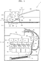
- FIG. 1 is a schematic diagram of an image forming apparatus 1 according to an embodiment.
- the image forming apparatus 1 includes a printing unit 2.
- the printing unit 2 may print images on a recording medium P in various printing methods, for example, an inkjet method, a thermal transfer method, an electrophotographic method, etc.
- the printing unit 2 according to an embodiment prints color images by using the electrophotographic method.
- the printing unit 2 includes a plurality of developing units 10 and a plurality of developing agent receiving units 20 in which a developing agent may be accommodated.
- the plurality of developing units 10 and the plurality of developing agent receiving units 20 may be connected to each other respectively through a plurality of developing agent supplying paths 15.
- the developing agents accommodated in the plurality of developing agent receiving units 20 may be respectively supplied to the plurality of developing units 10 via the plurality of developing agent supplying paths 15.
- the plurality of developing agent receiving units 20 and the plurality of developing units 10 may be independently replaced.
- the plurality of developing units 10 may include developing units 10C, 10M, 10Y, and 10K to respectively develop cyan (C), magenta (M), yellow (Y), and black (K) colors.
- the plurality of developing agent receiving units 20 may include developing agent receiving units 20C, 20M, 20Y, and 20K respectively including C, M, Y, and K developing agents that are to be supplied respectively to the plurality of developing units 10C, 10M, 10Y, and 10K.
- one or more embodiments are not limited thereto, and more developing agent receiving units 20 and developing units 10 to receive and develop other developing agents of various colors such as light magenta and white may be provided.
- the image forming apparatus including the plurality of developing units 10C, 10M, 10Y, and 10K and the plurality of developing agent receiving members 20C, 20M, 20Y, and 20K are described. Unless otherwise specified, references with Y, M, C, and K refer to elements for developing Y, M, C, and K developing agents, respectively.
- Each of the developing units 10 includes a photosensitive body 11.
- the photosensitive body 11 may have a cylindrical shape, on which a photosensitive layer is formed, however, one or more embodiments are not limited thereto.
- a charging roller 12 charges the photosensitive body 11 to have a uniform surface potential.
- a charging brush, a corona charger, and the like may be used instead of the charging roller 12.
- a developing roller 13 supplies a developing agent in the developing unit 10 to the photosensitive body 11.
- the developing unit 10 may include a charging roller cleaner to remove impurities such as the developing agent or dust attached to the charging roller 12, a cleaning member to remove the developing agent remaining on a surface of the photosensitive body 11 after an intermediate transfer process that will be described later, and a regulating member to regulate the amount of the developing agent supplied to a developing region where the photosensitive body 11 and the developing roller 13 face each other.
- a charging roller cleaner to remove impurities such as the developing agent or dust attached to the charging roller 12
- a cleaning member to remove the developing agent remaining on a surface of the photosensitive body 11 after an intermediate transfer process that will be described later
- a regulating member to regulate the amount of the developing agent supplied to a developing region where the photosensitive body 11 and the developing roller 13 face each other.
- a magnetic carrier may be accommodated in the developing unit 10, and the developing roller 13 is separated tens to hundreds of ⁇ m from the photosensitive body 11.
- the developing roller 13 may be a magnetic roller, or may include a developing sleeve and a magnetic roller disposed in the developing sleeve.
- the developing agent supplied from one of the developing agent receiving units 20 to the developing unit 10 is attached to a surface of the magnetic carrier.
- the magnetic carrier may be carried to the developing region where the photosensitive body 11 and the developing roller 13 face each other while being attached to the surface of the developing roller 13.
- the developing agent may be supplied to the photosensitive body 11 by a developing bias applied between the developing roller 13 and the photosensitive body 11 so as to develop an electrostatic latent image formed on the surface of the photosensitive body 11 into a visible image. If a mono-component development method that does not include a carrier is used, the developing roller 13 may rotate in contact with the photosensitive body 11 or may rotate while being separate by tens to hundreds of ⁇ m from the photosensitive body 11.
- the developing unit 10 may include an agitating/conveying member that mixes and agitates the developing agent supplied from the developing agent receiving unit 20 with the carrier in the developing unit 10 to supply the mixture to the developing roller 13.
- the developing unit 10 may include a conveying member that agitates the developing agent introduced from the developing agent receiving unit 20 and conveys the developing agent to the developing roller 13.
- the developing method of the image forming apparatus is described above, however, one or more embodiments are not limited thereto, and the developing method may be variously modified.
- a light scanning unit 40 irradiates light that may be modulated in correspondence with image information to the photosensitive body 11 to form an electrostatic latent image on the photosensitive body 11, and examples of the light scanning unit 40 may include a laser scanning unit (LSU) using a laser diode as a light source or a light scanning unit using a light-emitting diode (LED) as a light source.
- LSU laser scanning unit
- LED light-emitting diode
- the images formed on the photosensitive bodies 11 of the plurality of developing units 10C, 10M, 10Y, and 10K may be temporarily transferred on an intermediate transfer belt 30.
- a plurality of intermediate transfer rollers 50 are disposed to face the photosensitive bodies 11 of the plurality of developing units 10C, 10M, 10Y, and 10K with the intermediate transfer belt 30 interposed therebetween.
- An intermediate transfer bias may be applied to the plurality of intermediate transfer rollers 50 to transfer the images formed on the photosensitive bodies 11 to the intermediate transfer belt 30.
- a corona transfer unit or a transfer unit of a pin scorotron may be used instead of the intermediate transfer roller 50.
- a transfer roller 60 may be located facing the intermediate transfer belt 30.
- a transfer bias may be applied to the transfer roller 60 to transfer the image transferred on the intermediate transfer belt 30 to a recording medium P.
- the image formed on the photosensitive body 11 is intermediately transferred to the intermediate transfer belt 30, and then, is transferred to the recording medium P that passes between the intermediate transfer belt 30 and the transfer roller 60.
- embodiments are not limited thereto. That is, the recording medium P passes between the intermediate transfer belt 30 and the photosensitive body 11 so that the image is directly transferred to the recording medium P.
- the transfer roller 60 is not provided.
- a fusing device 80 applies heat and/or pressure to the image transferred onto the recording medium P to fuse the image in the recording medium P.
- the fusing device 80 is not limited to the example illustrated in FIG. 1 .
- the light scanning unit 40 irradiates a plurality of light rays that are modulated according to image information of each color to the photosensitive bodies 11 of the plurality of developing units 10C, 10M, 10Y, and 10K to form electrostatic latent images on the photosensitive bodies 11.
- the electrostatic latent images on the photosensitive bodies 11 of the plurality of developing units 10C, 10M, 10Y, and 10K are developed into visible images by the C, M, Y, and K developing agents supplied from the plurality of developing agent receiving units 20C, 20M, 20Y, and 20K to the plurality of developing units 10C, 10M, 10Y, and 10K.
- the visible images may be intermediately transferred to the intermediate transfer belt 30, for example, sequentially.
- the recording medium P loaded in a paper feed unit 70 may be conveyed along a paper feeding path 91 to a region where the transfer roller 60 and the intermediate transfer belt 30 face each other.
- the image formed on the intermediate transfer belt 30 may be transferred to the recording medium P by the transfer bias applied to the transfer roller 60.
- the recording medium P passes through the fusing device 80, the image is fixed on the recording medium P due to the heat and pressure.
- the recording medium P, on which the fusing of the image has finished, is discharged to a discharge unit 93. If a duplex printing is performed, a selection device 90 guides the recording medium P that has passed through the fusing device 80 so that the image may be printed on a surface thereof to a duplex printing path 92.
- the recording medium P may be supplied between the intermediate transfer belt 30 and the transfer roller 60 again, and another image is transferred to a rear surface of the recording medium P.
- the recording medium P passes through the fusing device 80 again, and, may be discharged to the discharge unit 93 by the selection device 90.
- the image forming apparatus 1 may include a scanner unit 3.
- the scanner unit 3 may include a document feeding unit 3-1 and a scanning unit 3-2.
- the scanning unit 3-2 includes a scanning member 320 to read images from a document.
- the scanning member 320 irradiates light to the document and receives light reflected by the document to read the images on the document.
- the scanning member 320 may be a contact-type image sensor (CIS) or a charge-coupled device (CCD).
- the scanner unit 3 is a combined-type scanner device, in which both a flatbed type scanning operation and a document feed type scanning operation are possible.
- the scanning unit 3-2 includes a platen glass 330, on which a document may be placed in order to read images from the document in the flatbed type scanning operation.
- the scanning unit 3-2 may include a scanning window 340 in order to read images from the document in the document feed type scanning operation.
- the scanning window 340 may be, for example, a transparent member.
- the scanning member 320 may be disposed under the scanning window 340.
- the scanning member 320 may be transferred in a sub-scanning direction S, that is, a lengthwise direction of the document, by a transfer unit (not illustrated) under the platen glass 330.
- the platen glass 330 may need to be exposed to the outside in order to place the document on the platen glass 330.
- the document feeding unit 3-1 may be rotated with respect to the scanning unit 3-2.
- the document feeding unit 3-1 moves the document so that the scanning member 320 may read an image recorded on the document and discharges the document that has been read.
- the document feeding unit 3-1 includes a document feeding path, and the scanning member 320 reads the image from the document that is fed through the document feeding path.
- the document feeding path may include a supply path 351, a scanning path 352, and a discharge path 353.
- the scanning member 320 may be disposed on the scanning path 352, and the image recorded on the document is read by the scanning member 320 while the document passes through the scanning path 352.
- the supply path 351 is a path to supply the document to the scanning path 352, and the document loaded in a supply tray 361 is supplied to the scanning path 352 via the supply path 351.
- the discharge path 353 is a path discharge the document that has passed through the scanning path 352. Therefore, the document loaded in the supply tray 361 is transferred along the supply path 351, the scanning path 352, and the discharge path 353, and then, is discharged to a discharge tray 362.
- An automatic document feed (ADF) unit 310 separates documents loaded in the supply tray 361 one-by-one and supplies the document to the supply path 351.
- the ADF unit 310 may include a first ADF roller 311 and a second ADF roller 312 that are engaged with each other to rotate in opposite directions to each other.
- the first ADF roller 311 rotates in a direction in which the document is transferred to the supply path 351, and the second ADF roller 312 rotates in an opposite direction thereto. If two or more documents are supplied between the first and second ADF rollers 312 and 312, the first and second ADF rollers 311 and 312 may separate only one document by using a difference between frictional forces and supply the document to the supply path 351.
- Supply rollers 313 and 314 to transfer the document may be disposed on the supply path 351.
- a feeding roller 315 to transfer the document may be disposed on the scanning path 352 to face the scanning member 320.
- a discharge roller 316 to discharge the document, on which the reading operation is finished, may be disposed on the discharge path 353.
- the document, a surface of which has been read may be supplied to the scanning path 352 again via a re-supply path 354.
- a re-supply roller 317 may be disposed on the re-supply path 354.
- Each of the supply rollers 313 and 314, the discharge roller 316, and the re-supply roller 317 may include a pair of rollers that are rotated while engaged with each other to transfer the document.
- One roller of the pair of rollers may be a driving roller and the other may be a driven roller that may be rotated by being compressed by the driving roller.
- one or more sensors to sense the document may be disposed on the document feeding path.
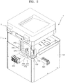
- FIG. 2 is a partially exploded perspective view of the image forming apparatus 1 illustrated from a rear of the image forming apparatus 1.
- the image forming apparatus 1 includes a main control unit 210.
- the main control unit 210 controls operations of the image forming apparatus 1, which include printing processes and image reading processes.
- the main control unit 210 may be electrically connected to the components of the image forming apparatus 1 to transmit/receive control signals to control operations of the components to/from the components.
- the main control unit 210 may be configured as a central processing unit (CPU) or a circuit board including the CPU.
- CPU central processing unit
- Each of elements included in the main control unit 210 may be realized by software stored in a memory of the main control unit 210, or electrical circuits.
- the image forming apparatus 1 has a printing function, and a scanning function. Functions of the image forming apparatus 1 may be expanded when an option kit is installed on the image forming apparatus 1. For example, functions such as a facsimile function using one or more telephone wires, a Wi-Fi communication function to connect to an external device or an external host via wireless communication, or a network communication unction to connect to an external device or an external host via wired communication may be added as a function of the image forming apparatus 1. To do this, one or more option kits may be installed to the image forming apparatus 1. The user may expand the functions of the image forming apparatus 1, for example, by buying and installing an option kit on the image forming apparatus 1.
- the image forming apparatus 1 may include an adaptor 400 on which two or more option kits, namely, first and second option kits 510 and 520, (see, for example, FIG. 5 ) may be installed, an installation member 230 on which the adaptor 400 may be installed, and an option interface unit 220 to form an electric interface between the first and second option kits 510 and 520 (see, for example, FIG. 5 ) and the main control unit 210.
- An installation hole 102 to install the adaptor 400 may be formed in a housing 101 that forms an outer appearance of the image forming apparatus 1.
- a cover 110 covers the installation hole 102. The cover 110 may be removed in order to install the adaptor 400.
- FIG. 3 is a perspective view of the installation hole 102 and the cover 110
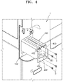
- FIG. 4 is a perspective view illustrating the adaptor 400 that may be installed on the image forming apparatus 1 via the installation hole 102.
- the cover 110 may be connected to an edge of the installation hole 102 by a plurality of connecting protrusions 112 to block the installation hole 102.
- the cover 110 may be integrally formed with the housing 101. Before installing the adaptor 400, the cover 110 may be removed to open the installation hole 102400 by cutting the plurality of connecting protrusions 112. Since the housing 101 may be manufactured by, for example, a plastic molding process, the cover 110 may be easily removed by using a tool or applying a force to the cover 110.
- the cover 110 that is removable in FIG. 3 is an example, and embodiments are not limited thereto.
- the cover 110 may be detachably coupled to the housing 101 in a screw coupling method or a snap fit coupling method.
- the installation hole 102 may be opened as illustrated in FIG. 3 .
- the adaptor 400 may be pushed into the image forming apparatus 1 via the installation hole 102 so that the adaptor 400 may be installed in the image forming apparatus 1.
- the adaptor 400 may be fixed in the image forming apparatus 1 by using coupling members, for example, screws S, through fixing holes 452 in a fixing bracket 450.
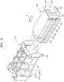
- FIG. 5 is an exploded perspective view of the adaptor 400.
- two option kits namely, the first and second option kits 510 and 520, may be installed on the adaptor 400.
- the adaptor 400 includes a first member 410 and a second member 420 located at a side of the first member 410 (for example, a lower portion of the first member 410 in FIG. 5 ) to form a first accommodation space 401, in which the first option kit 510 is accommodated, with the first member 410.
- the adaptor 400 may include a third member 430 located at the other side of the first member 410 (for example, an upper portion of the first member 410 in FIG. 5 ) to form a second accommodation space 402, in which the second option kit 520 is accommodated, with the first member 410.
- the adaptor 400 may include a ground bracket 440 to ground the first and second option kits 510 and 520.
- the adaptor 400 may include the fixing bracket 450 to block the installation hole 102, when the adaptor 400 is installed in the image forming apparatus 1.
- the fixing bracket 450 may be integrally formed with, for example, the second member 420, and may be coupled to the second member 420.
- the fixing bracket 450 may include a connecting hole 451 to connect the first and second option kits 510 and 520 to the outside (for example, a telephone line or a network communication line).
- the first option kit 510 may be disposed between the first and second members 410 and 420 and the second option kit 520 may be disposed between the first and third members 410 and 430.
- the ground bracket 440 may be disposed to contact ground portions of circuit patterns in the first and second option kits 510 and 520.
- a screw Si and a screw S2 may be coupled to each other, and thus, the first, second, and third members 410, 420, and 430 may be coupled to one another, and at the same time, the first and second option kits 510 and 520 may be accommodated in the adaptor 400.
- FIG. 6 is a perspective view of the installation member 230 in which the adaptor 400 is installed.
- the installation member 230 may include an accommodation space 231, in which the adaptor 400 is accommodated, and a fixing hook 232 fixed on the image forming apparatus 1.
- the image forming apparatus 1 includes a supporting bracket 240 to support the main control unit 210, and the fixing hook 232 may be fixed on the supporting bracket 240 after penetrating through the main control unit 210.
- the option interface unit 220 may be located in the accommodation space 231 of the installation member 230.
- the installation member 230 may include a guide portion 233 that supports the adaptor 400 so that the adaptor 400 may slide in an installation direction A and is guided to the accommodation space 231 when the adaptor 400 is installed.
- the adaptor 400 may include a guide rail 460 extending in the installation direction A, and the guide portion 233 may be formed as a recess extending in the installation direction A to support the guide rail 460.
- the guide portion 233 may include, for example, a first protrusion 233-1 and a second protrusion 233-2 that protrude from opposite walls 234 of the installation member 230 and are separated by a predetermined interval from each other.
- the option interface unit 220 includes a connecting portion 223 that is electrically connected to connectors 511 and 521 disposed on the first and second option kits 510 and 520.
- the option interface unit 220 connects the two or more option kits, namely, the first and second option kits 510 and 520, to the main control unit 210.
- the connection portion 223 includes a first connection portion 221 and a second connection portion 222.
- the first connection portion 221 is connected to the connector 511 of the first option kit 510, and the second connection portion 222 is connected to the connector 521 of the second option kit 520.
- the first and second connection portions 221 and 222 may have any kind of structures, provided that they are electrically connected to the connectors 511 and 521, respectively, and a scope is not limited by the structures of the first and second connection portions 221 and 222.
- the first and second connection portions 221 and 222 may be connected to the connectors 511 and 512 in a male-and-female coupling method.
- the option interface unit 220 may be disposed on a circuit board forming the main control unit 210.
- the option interface unit 220 may be separated from the main control unit 210 and may be connected to the main control unit 210 via a signal line.
- the option interface unit 220 may be formed as a circuit board including the first and second connection portions 221 and 222 and may be coupled to the main control unit 210.
- the adaptor 400 is prepared.
- the adaptor 400 may be provided to a user in a preliminary assembled state. Otherwise, the adaptor 400 may be provided to the user in a disassembled state.
- the first and second option kits 510 and 520 may be respectively inserted between the first and second members 410 and 420 and between the first and third members 410 and 430, as illustrated in FIG. 5 .
- the adaptor 400 may be assembled by using the screws Si and S2.
- the adaptor 400 may be provided to the user in a state where the first and second option kits 510 and 520 are installed thereon.
- the installation hole 102 may be opened.
- the installation hole 102 may be opened by cutting the connecting protrusions 112, by removing the screws, or by releasing the snap fit connecting structure.
- the adaptor 400 may be inserted into the image forming apparatus 1 through the installation hole 102.
- the guide rail 460 of the adaptor 400 may be supported by the guide portion 233 of the installation member 230.
- the connectors 511 and 521 of the first and second option kits 510 and 520 are respectively connected to the first and second connection portions 221 and 222 of the option interface unit 220.
- the adaptor 400 may be fixed in the image forming apparatus 1 by using, for example, a screw S, and then, the installation of the adaptor 400 is finished.
- the installation member 230 including a kind of guide portion 233 and the option interface unit 220 including two connecting portions, for example, the first and second connecting portions 221 and 222, may be provided in the image forming apparatus 1 so that the adaptor 400 including the first and second option kits 510 and 520 may be installed in the image forming apparatus 1.
- the two option kits may be installed in the image forming apparatus 1 through different installation holes.
- the option kits have different external sizes, guide portions formed in the two installation members may have to be formed in different structures. Therefore, the number of components in the image forming apparatus 1 may be increased and costs for components and manufacturing costs may be increased.
- the image forming apparatus 1 may have to be partially disassembled before installing the first and second option kits 510 and 520, and, the two installation members are installed in the image forming apparatus 1. Therefore, processes of installing the first and second option kits 510 and 520 become complicated and internal components of the image forming apparatus 1 may be damaged during disassembling and assembling processes.
- FIG. 7 is a systemic block diagram of the image forming apparatus 1 in which two option kits, namely, the first and second option kits 510 and 520, are installed.
- the first option kit 510 is a single fax card
- the second option kit 520 is a dual fax card.
- the image forming apparatus 1 may operate as a fax using two telephone lines (telephone line 1 and telephone line 2).
- the main control unit 210 may include a processor 211, a memory 213, and a user interface unit 214.
- the processor 211 may be formed by an electric circuit including a CPU and controls overall operations of the image forming apparatus 1.
- the processor 211 may be driven by, for example, software stored in the memory 213, or may be driven by software provided from a host 4.
- the user interface unit 214 may be connected to, for example, an input device (not illustrated) to input a manipulation command of the user and an output device (not illustrated) to display operational states of the image forming apparatus 1.
- the user interface unit 214 receives the manipulation command of the user via the input device and transmits an output signal to the output device so as to display the operational state of the image forming apparatus 1.
- the first and second option kits 510 and 520 may be respectively connected to the first and second connection portions 221 and 222 of the option interface unit 220 so as to exchange signals with the main control unit 210.
- the main control unit 210 receives installation signals of the first and second option kits 510 and 520 via an installation sensing unit 215.
- the main control unit 210 recognizes that the two telephone lines are available.
- the main control unit 210 receives image information provided from the host 4 and controls a printing unit 2 so as to print an image on the recording medium P.
- the main control unit 210 reads image information that is read from the document by using the scanner unit 3 and controls the printing unit 2 to print the read image information on the recording medium P.
- the main control unit 210 may control the first option kit 510 and/or the second option kit 520 to transmit the read image information via the telephone line 1 and/or the telephone line 2.
- the main control unit 210 may control the first option kit 510 and/or the second option kit 520 to receive the image information via the local 1 and/or the local 2 and may control the printing unit 2 to print the image information on the recording medium P.
- the first and second option kits 510 and 520 are the single fax card and the dual fax card; however, the embodiments are not limited thereto.
- the first and second option kits 510 and 520 may be combinations of the single fax card, a Wi-Fi card, and a network card or other suitable hardware.
- the image forming apparatus 1 may be connected to a router connected to an infrastructure network, that is, an access point (AP).
- the Wi-Fi card may have a Wi-Fi direct (WFD) function.
- the image forming apparatus 1 may function as a multi-functional apparatus supporting WFD. According to the WFD function, one of the WFD devices that are to form a wireless network performs as an AP, and the other WFD devices perform as stations that are wirelessly connected to the WFD device performing as the AP. Therefore, the WFD devices may form the wireless network without an AP connected to the infrastructure network.
- wireless LAN devices such as Wi-Fi devices may recognize the WFD device performing as the AP as an AP and may be wirelessly connected to the WFD device.
- the image forming apparatus 1 When the network card is installed, the image forming apparatus 1 may be connected to the infrastructure network through wires. Therefore, the image forming apparatus 1 may perform as a network printer or a network scanner.
- the adaptor 400 includes two option kits, namely, the first and second option kits 510 and 520; however, the embodiments are not limited thereto. Although not illustrated in the drawings, the adaptor 400 may have a structure in which three or more option kits may be accommodated.
- the option interface unit 220 may include three or more connection portions.
Landscapes
- Physics & Mathematics (AREA)
- General Physics & Mathematics (AREA)
- Accessory Devices And Overall Control Thereof (AREA)
- Electrophotography Configuration And Component (AREA)
- Facsimiles In General (AREA)
Claims (7)
- Bilderzeugungsvorrichtung (1), die Folgendes umfasst:eine Druckeinheit (2), um Bilder auf ein Aufzeichnungsmedium (P) zu drucken;ein Einbauelement (230), das einen Aufnahmeraum (401, 402) aufweist; undeinen Adapter (400), auf den zwei oder mehr Optionskits (510, 520) geladen sind, die an dem Aufnahmeraum des Einbauelements abnehmbar angebracht sind;eine Hauptsteuereinheit (210), um Vorgänge der Bilderzeugungsvorrichtung zu steuern; undeine Optionsschnittstelleneinheit (220), um sich mit dem Adapter zu verbinden, wenn der Adapter in dem Einbauelement eingebaut ist, um die zwei oder mehr Optionssätze mit der Hauptsteuereinheit zu verbinden, wobei die Optionsschnittstelleneinheit zwei oder mehr Verbindungabschnitte (221, 222) umfasst, die jeweils mit den zwei oder mehr Optionskits verbunden sind, wenn der Adapter in dem Einbauelement eingebaut ist.
- Bilderzeugungsvorrichtung nach Anspruch 1, wobei der Adapter eine Führungsschiene (460) umfasst und das Einbauelement eine Führungseinheit umfasst, um die Führungsschiene zu tragen, um den Adapter zu dem Aufnahmeraum zu führen.
- Bilderzeugungsvorrichtung nach Anspruch 1, die ferner ein Gehäuse (101) umfasst, das ein Einbauloch (102) aufweist, wobei eine Abdeckung (110), die entfernbar ist, auf dem Einbauloch angeordnet ist.
- Bilderzeugungsvorrichtung nach Anspruch 3, wobei der Adapter ferner eine Befestigungshalterung (450) umfasst, um das Einbauloch zu blockieren.
- Bilderzeugungsvorrichtung nach Anspruch 4, wobei die Befestigungshalterung ein Verbindungsloch (451) umfasst, um die zwei oder mehr Optionskits mit der Außenseite zu verbinden.
- Bilderzeugungsvorrichtung nach Anspruch 6 oder 5, wobei die Befestigungshalterung ein Befestigungsloch beinhaltet, um den Adapter zu befestigen.
- Bilderzeugungsvorrichtung nach einem der Ansprüche 1 bis 6, wobei die zwei oder mehr Optionskits wenigstens zwei aus einer Faxkarte, einer Wireless-Fidelity(Wi-Fi)-Karte und einer Netzwerkkarte beinhalten.
Applications Claiming Priority (1)
| Application Number | Priority Date | Filing Date | Title |
|---|---|---|---|
| KR1020140042537A KR20150117138A (ko) | 2014-04-09 | 2014-04-09 | 옵션 키트 어댑터 및 이를 채용한 화상형성장치 |
Publications (3)
| Publication Number | Publication Date |
|---|---|
| EP2940533A2 EP2940533A2 (de) | 2015-11-04 |
| EP2940533A3 EP2940533A3 (de) | 2016-02-10 |
| EP2940533B1 true EP2940533B1 (de) | 2021-03-10 |
Family
ID=52440593
Family Applications (1)
| Application Number | Title | Priority Date | Filing Date |
|---|---|---|---|
| EP15153362.7A Active EP2940533B1 (de) | 2014-04-09 | 2015-01-30 | Option-Satz Adapter und Bilderzeugungsvorrichtung damit |
Country Status (3)
| Country | Link |
|---|---|
| US (1) | US9405265B2 (de) |
| EP (1) | EP2940533B1 (de) |
| KR (1) | KR20150117138A (de) |
Families Citing this family (2)
| Publication number | Priority date | Publication date | Assignee | Title |
|---|---|---|---|---|
| JP6475155B2 (ja) * | 2015-12-25 | 2019-02-27 | 株式会社沖データ | 基板取付機構、現像剤収容器、画像形成ユニット及び画像形成装置 |
| JP6551299B2 (ja) * | 2016-05-18 | 2019-07-31 | 京セラドキュメントソリューションズ株式会社 | 画像形成装置 |
Citations (1)
| Publication number | Priority date | Publication date | Assignee | Title |
|---|---|---|---|---|
| US4908637A (en) * | 1989-01-30 | 1990-03-13 | Acer Incorporated | Font cartridge adapter |
Family Cites Families (13)
| Publication number | Priority date | Publication date | Assignee | Title |
|---|---|---|---|---|
| US4388010A (en) | 1980-12-31 | 1983-06-14 | International Business Machines Corporation | Font module for matrix printer |
| US4730947A (en) | 1985-08-19 | 1988-03-15 | Citizen Watch Co., Ltd. | Printer having a control circuit section of cassette type |
| JP2853908B2 (ja) * | 1990-12-04 | 1999-02-03 | 株式会社リコー | プリンタの拡張オプションボード |
| US5481656A (en) | 1993-06-18 | 1996-01-02 | Seiko Epson Corporation | Accessory control device and information processing method |
| JPH07304231A (ja) * | 1994-05-09 | 1995-11-21 | Hewlett Packard Co <Hp> | 画像形成装置 |
| JPH118025A (ja) | 1997-06-16 | 1999-01-12 | Amp Japan Ltd | 回路装置 |
| US6412749B1 (en) * | 1998-04-30 | 2002-07-02 | Ati Technologies, Inc. | Bracket for mounting an expansion card and method therefore |
| US6282099B1 (en) * | 1998-05-15 | 2001-08-28 | Hewlett-Packard Company | Structure for mounting and method for installing a circuit card |
| KR20020089744A (ko) | 2001-05-24 | 2002-11-30 | 삼성전자 주식회사 | 팩스 데이터의 선택적 인쇄가 가능한 팩시밀리 겸용프린터 및 팩스 데이터의 선택적 인쇄방법 |
| US7143940B2 (en) * | 2002-11-15 | 2006-12-05 | Hewlett-Packard Development Company, L.P. | Electronic device that accepts an accessory card, and design methodology therefor |
| CN103105909B (zh) * | 2011-11-14 | 2016-04-27 | 河南农业大学 | 具有扩展卡模组的服务器 |
| CN104335555B (zh) * | 2012-05-04 | 2017-11-17 | 诺基亚技术有限公司 | 用于接受多个存储卡的装置 |
| CN104281230A (zh) * | 2013-07-08 | 2015-01-14 | 鸿富锦精密电子(天津)有限公司 | 电子装置及其扩展卡模组 |
-
2014
- 2014-04-09 KR KR1020140042537A patent/KR20150117138A/ko not_active Withdrawn
- 2014-09-02 US US14/474,577 patent/US9405265B2/en active Active
-
2015
- 2015-01-30 EP EP15153362.7A patent/EP2940533B1/de active Active
Patent Citations (1)
| Publication number | Priority date | Publication date | Assignee | Title |
|---|---|---|---|---|
| US4908637A (en) * | 1989-01-30 | 1990-03-13 | Acer Incorporated | Font cartridge adapter |
Also Published As
| Publication number | Publication date |
|---|---|
| EP2940533A2 (de) | 2015-11-04 |
| US20150293491A1 (en) | 2015-10-15 |
| KR20150117138A (ko) | 2015-10-19 |
| US9405265B2 (en) | 2016-08-02 |
| EP2940533A3 (de) | 2016-02-10 |
Similar Documents
| Publication | Publication Date | Title |
|---|---|---|
| JP7353778B2 (ja) | 画像形成装置 | |
| JP2015138246A (ja) | 画像形成装置 | |
| US6366747B1 (en) | Customizable control panel for a functionally upgradable image printing machine | |
| EP0854399A2 (de) | Modulares Mehrmoden-Vervielfältigungsgerät | |
| JP2010107825A (ja) | 画像読取装置及び画像形成装置 | |
| KR101505092B1 (ko) | 화상 처리 장치 및 화상 형성 장치 | |
| CN110632837B (zh) | 处理盒、以及具备处理盒的图像形成装置 | |
| US9405265B2 (en) | Option kit adaptor and image forming apparatus employing the same | |
| US20130135652A1 (en) | Image forming apparatus | |
| US11061360B2 (en) | Image forming apparatus | |
| JP2010026129A (ja) | 画像形成装置、制御装置、およびプログラム | |
| KR20130084092A (ko) | 화상형성장치 | |
| US20090073478A1 (en) | Image forming apparatus | |
| JP7770887B2 (ja) | 画像形成装置 | |
| JP2016114723A (ja) | 画像形成ユニット及びこれを備えた画像形成装置 | |
| JP6722405B2 (ja) | 画像形成装置、及び搭載部材 | |
| US9420131B2 (en) | Image forming apparatus having electrical unit projecting from top surface | |
| JP4219359B2 (ja) | 画像形成装置、画像処理装置、及び画像形成システム | |
| JP4765420B2 (ja) | 画像形成装置 | |
| WO2021065566A1 (ja) | 画像形成装置 | |
| JP2908037B2 (ja) | 画像記録装置 | |
| JP2011253119A (ja) | 画像形成装置 | |
| JP4538300B2 (ja) | 画像形成装置 | |
| JP2009217058A (ja) | 画像形成装置及び同装置の制御方法 | |
| JP4365203B2 (ja) | 画像形成装置 |
Legal Events
| Date | Code | Title | Description |
|---|---|---|---|
| PUAI | Public reference made under article 153(3) epc to a published international application that has entered the european phase |
Free format text: ORIGINAL CODE: 0009012 |
|
| 17P | Request for examination filed |
Effective date: 20150130 |
|
| AK | Designated contracting states |
Kind code of ref document: A2 Designated state(s): AL AT BE BG CH CY CZ DE DK EE ES FI FR GB GR HR HU IE IS IT LI LT LU LV MC MK MT NL NO PL PT RO RS SE SI SK SM TR |
|
| AX | Request for extension of the european patent |
Extension state: BA ME |
|
| PUAL | Search report despatched |
Free format text: ORIGINAL CODE: 0009013 |
|
| AK | Designated contracting states |
Kind code of ref document: A3 Designated state(s): AL AT BE BG CH CY CZ DE DK EE ES FI FR GB GR HR HU IE IS IT LI LT LU LV MC MK MT NL NO PL PT RO RS SE SI SK SM TR |
|
| AX | Request for extension of the european patent |
Extension state: BA ME |
|
| RIC1 | Information provided on ipc code assigned before grant |
Ipc: G03G 21/16 20060101AFI20160107BHEP |
|
| RAP1 | Party data changed (applicant data changed or rights of an application transferred) |
Owner name: S-PRINTING SOLUTION CO., LTD. |
|
| RAP1 | Party data changed (applicant data changed or rights of an application transferred) |
Owner name: HP PRINTING KOREA CO., LTD. |
|
| STAA | Information on the status of an ep patent application or granted ep patent |
Free format text: STATUS: EXAMINATION IS IN PROGRESS |
|
| RAP1 | Party data changed (applicant data changed or rights of an application transferred) |
Owner name: HEWLETT-PACKARD DEVELOPMENT COMPANY, L.P. |
|
| 17Q | First examination report despatched |
Effective date: 20191128 |
|
| GRAP | Despatch of communication of intention to grant a patent |
Free format text: ORIGINAL CODE: EPIDOSNIGR1 |
|
| STAA | Information on the status of an ep patent application or granted ep patent |
Free format text: STATUS: GRANT OF PATENT IS INTENDED |
|
| INTG | Intention to grant announced |
Effective date: 20201106 |
|
| GRAS | Grant fee paid |
Free format text: ORIGINAL CODE: EPIDOSNIGR3 |
|
| GRAA | (expected) grant |
Free format text: ORIGINAL CODE: 0009210 |
|
| STAA | Information on the status of an ep patent application or granted ep patent |
Free format text: STATUS: THE PATENT HAS BEEN GRANTED |
|
| AK | Designated contracting states |
Kind code of ref document: B1 Designated state(s): AL AT BE BG CH CY CZ DE DK EE ES FI FR GB GR HR HU IE IS IT LI LT LU LV MC MK MT NL NO PL PT RO RS SE SI SK SM TR |
|
| REG | Reference to a national code |
Ref country code: GB Ref legal event code: FG4D |
|
| REG | Reference to a national code |
Ref country code: AT Ref legal event code: REF Ref document number: 1370504 Country of ref document: AT Kind code of ref document: T Effective date: 20210315 Ref country code: CH Ref legal event code: EP |
|
| REG | Reference to a national code |
Ref country code: DE Ref legal event code: R096 Ref document number: 602015066569 Country of ref document: DE |
|
| REG | Reference to a national code |
Ref country code: IE Ref legal event code: FG4D |
|
| REG | Reference to a national code |
Ref country code: LT Ref legal event code: MG9D |
|
| PG25 | Lapsed in a contracting state [announced via postgrant information from national office to epo] |
Ref country code: GR Free format text: LAPSE BECAUSE OF FAILURE TO SUBMIT A TRANSLATION OF THE DESCRIPTION OR TO PAY THE FEE WITHIN THE PRESCRIBED TIME-LIMIT Effective date: 20210611 Ref country code: HR Free format text: LAPSE BECAUSE OF FAILURE TO SUBMIT A TRANSLATION OF THE DESCRIPTION OR TO PAY THE FEE WITHIN THE PRESCRIBED TIME-LIMIT Effective date: 20210310 Ref country code: FI Free format text: LAPSE BECAUSE OF FAILURE TO SUBMIT A TRANSLATION OF THE DESCRIPTION OR TO PAY THE FEE WITHIN THE PRESCRIBED TIME-LIMIT Effective date: 20210310 Ref country code: LT Free format text: LAPSE BECAUSE OF FAILURE TO SUBMIT A TRANSLATION OF THE DESCRIPTION OR TO PAY THE FEE WITHIN THE PRESCRIBED TIME-LIMIT Effective date: 20210310 Ref country code: BG Free format text: LAPSE BECAUSE OF FAILURE TO SUBMIT A TRANSLATION OF THE DESCRIPTION OR TO PAY THE FEE WITHIN THE PRESCRIBED TIME-LIMIT Effective date: 20210610 Ref country code: NO Free format text: LAPSE BECAUSE OF FAILURE TO SUBMIT A TRANSLATION OF THE DESCRIPTION OR TO PAY THE FEE WITHIN THE PRESCRIBED TIME-LIMIT Effective date: 20210610 |
|
| REG | Reference to a national code |
Ref country code: AT Ref legal event code: MK05 Ref document number: 1370504 Country of ref document: AT Kind code of ref document: T Effective date: 20210310 |
|
| REG | Reference to a national code |
Ref country code: NL Ref legal event code: MP Effective date: 20210310 |
|
| PG25 | Lapsed in a contracting state [announced via postgrant information from national office to epo] |
Ref country code: SE Free format text: LAPSE BECAUSE OF FAILURE TO SUBMIT A TRANSLATION OF THE DESCRIPTION OR TO PAY THE FEE WITHIN THE PRESCRIBED TIME-LIMIT Effective date: 20210310 Ref country code: RS Free format text: LAPSE BECAUSE OF FAILURE TO SUBMIT A TRANSLATION OF THE DESCRIPTION OR TO PAY THE FEE WITHIN THE PRESCRIBED TIME-LIMIT Effective date: 20210310 Ref country code: LV Free format text: LAPSE BECAUSE OF FAILURE TO SUBMIT A TRANSLATION OF THE DESCRIPTION OR TO PAY THE FEE WITHIN THE PRESCRIBED TIME-LIMIT Effective date: 20210310 |
|
| PG25 | Lapsed in a contracting state [announced via postgrant information from national office to epo] |
Ref country code: NL Free format text: LAPSE BECAUSE OF FAILURE TO SUBMIT A TRANSLATION OF THE DESCRIPTION OR TO PAY THE FEE WITHIN THE PRESCRIBED TIME-LIMIT Effective date: 20210310 |
|
| PG25 | Lapsed in a contracting state [announced via postgrant information from national office to epo] |
Ref country code: SM Free format text: LAPSE BECAUSE OF FAILURE TO SUBMIT A TRANSLATION OF THE DESCRIPTION OR TO PAY THE FEE WITHIN THE PRESCRIBED TIME-LIMIT Effective date: 20210310 Ref country code: AT Free format text: LAPSE BECAUSE OF FAILURE TO SUBMIT A TRANSLATION OF THE DESCRIPTION OR TO PAY THE FEE WITHIN THE PRESCRIBED TIME-LIMIT Effective date: 20210310 Ref country code: CZ Free format text: LAPSE BECAUSE OF FAILURE TO SUBMIT A TRANSLATION OF THE DESCRIPTION OR TO PAY THE FEE WITHIN THE PRESCRIBED TIME-LIMIT Effective date: 20210310 Ref country code: EE Free format text: LAPSE BECAUSE OF FAILURE TO SUBMIT A TRANSLATION OF THE DESCRIPTION OR TO PAY THE FEE WITHIN THE PRESCRIBED TIME-LIMIT Effective date: 20210310 |
|
| PG25 | Lapsed in a contracting state [announced via postgrant information from national office to epo] |
Ref country code: SK Free format text: LAPSE BECAUSE OF FAILURE TO SUBMIT A TRANSLATION OF THE DESCRIPTION OR TO PAY THE FEE WITHIN THE PRESCRIBED TIME-LIMIT Effective date: 20210310 Ref country code: RO Free format text: LAPSE BECAUSE OF FAILURE TO SUBMIT A TRANSLATION OF THE DESCRIPTION OR TO PAY THE FEE WITHIN THE PRESCRIBED TIME-LIMIT Effective date: 20210310 Ref country code: PT Free format text: LAPSE BECAUSE OF FAILURE TO SUBMIT A TRANSLATION OF THE DESCRIPTION OR TO PAY THE FEE WITHIN THE PRESCRIBED TIME-LIMIT Effective date: 20210712 Ref country code: PL Free format text: LAPSE BECAUSE OF FAILURE TO SUBMIT A TRANSLATION OF THE DESCRIPTION OR TO PAY THE FEE WITHIN THE PRESCRIBED TIME-LIMIT Effective date: 20210310 Ref country code: ES Free format text: LAPSE BECAUSE OF FAILURE TO SUBMIT A TRANSLATION OF THE DESCRIPTION OR TO PAY THE FEE WITHIN THE PRESCRIBED TIME-LIMIT Effective date: 20210310 Ref country code: IS Free format text: LAPSE BECAUSE OF FAILURE TO SUBMIT A TRANSLATION OF THE DESCRIPTION OR TO PAY THE FEE WITHIN THE PRESCRIBED TIME-LIMIT Effective date: 20210710 |
|
| REG | Reference to a national code |
Ref country code: DE Ref legal event code: R097 Ref document number: 602015066569 Country of ref document: DE |
|
| PLBE | No opposition filed within time limit |
Free format text: ORIGINAL CODE: 0009261 |
|
| STAA | Information on the status of an ep patent application or granted ep patent |
Free format text: STATUS: NO OPPOSITION FILED WITHIN TIME LIMIT |
|
| PG25 | Lapsed in a contracting state [announced via postgrant information from national office to epo] |
Ref country code: DK Free format text: LAPSE BECAUSE OF FAILURE TO SUBMIT A TRANSLATION OF THE DESCRIPTION OR TO PAY THE FEE WITHIN THE PRESCRIBED TIME-LIMIT Effective date: 20210310 Ref country code: AL Free format text: LAPSE BECAUSE OF FAILURE TO SUBMIT A TRANSLATION OF THE DESCRIPTION OR TO PAY THE FEE WITHIN THE PRESCRIBED TIME-LIMIT Effective date: 20210310 |
|
| PGFP | Annual fee paid to national office [announced via postgrant information from national office to epo] |
Ref country code: GB Payment date: 20211216 Year of fee payment: 8 Ref country code: FR Payment date: 20211215 Year of fee payment: 8 |
|
| 26N | No opposition filed |
Effective date: 20211213 |
|
| PG25 | Lapsed in a contracting state [announced via postgrant information from national office to epo] |
Ref country code: SI Free format text: LAPSE BECAUSE OF FAILURE TO SUBMIT A TRANSLATION OF THE DESCRIPTION OR TO PAY THE FEE WITHIN THE PRESCRIBED TIME-LIMIT Effective date: 20210310 |
|
| PG25 | Lapsed in a contracting state [announced via postgrant information from national office to epo] |
Ref country code: IT Free format text: LAPSE BECAUSE OF FAILURE TO SUBMIT A TRANSLATION OF THE DESCRIPTION OR TO PAY THE FEE WITHIN THE PRESCRIBED TIME-LIMIT Effective date: 20210310 |
|
| PG25 | Lapsed in a contracting state [announced via postgrant information from national office to epo] |
Ref country code: IS Free format text: LAPSE BECAUSE OF FAILURE TO SUBMIT A TRANSLATION OF THE DESCRIPTION OR TO PAY THE FEE WITHIN THE PRESCRIBED TIME-LIMIT Effective date: 20210710 |
|
| PG25 | Lapsed in a contracting state [announced via postgrant information from national office to epo] |
Ref country code: MC Free format text: LAPSE BECAUSE OF FAILURE TO SUBMIT A TRANSLATION OF THE DESCRIPTION OR TO PAY THE FEE WITHIN THE PRESCRIBED TIME-LIMIT Effective date: 20210310 |
|
| REG | Reference to a national code |
Ref country code: CH Ref legal event code: PL |
|
| REG | Reference to a national code |
Ref country code: BE Ref legal event code: MM Effective date: 20220131 |
|
| PG25 | Lapsed in a contracting state [announced via postgrant information from national office to epo] |
Ref country code: LU Free format text: LAPSE BECAUSE OF NON-PAYMENT OF DUE FEES Effective date: 20220130 |
|
| PG25 | Lapsed in a contracting state [announced via postgrant information from national office to epo] |
Ref country code: BE Free format text: LAPSE BECAUSE OF NON-PAYMENT OF DUE FEES Effective date: 20220131 |
|
| PG25 | Lapsed in a contracting state [announced via postgrant information from national office to epo] |
Ref country code: LI Free format text: LAPSE BECAUSE OF NON-PAYMENT OF DUE FEES Effective date: 20220131 Ref country code: CH Free format text: LAPSE BECAUSE OF NON-PAYMENT OF DUE FEES Effective date: 20220131 |
|
| PG25 | Lapsed in a contracting state [announced via postgrant information from national office to epo] |
Ref country code: IE Free format text: LAPSE BECAUSE OF NON-PAYMENT OF DUE FEES Effective date: 20220130 |
|
| GBPC | Gb: european patent ceased through non-payment of renewal fee |
Effective date: 20230130 |
|
| PG25 | Lapsed in a contracting state [announced via postgrant information from national office to epo] |
Ref country code: GB Free format text: LAPSE BECAUSE OF NON-PAYMENT OF DUE FEES Effective date: 20230130 |
|
| PG25 | Lapsed in a contracting state [announced via postgrant information from national office to epo] |
Ref country code: FR Free format text: LAPSE BECAUSE OF NON-PAYMENT OF DUE FEES Effective date: 20230131 |
|
| PG25 | Lapsed in a contracting state [announced via postgrant information from national office to epo] |
Ref country code: HU Free format text: LAPSE BECAUSE OF FAILURE TO SUBMIT A TRANSLATION OF THE DESCRIPTION OR TO PAY THE FEE WITHIN THE PRESCRIBED TIME-LIMIT; INVALID AB INITIO Effective date: 20150130 |
|
| PG25 | Lapsed in a contracting state [announced via postgrant information from national office to epo] |
Ref country code: MK Free format text: LAPSE BECAUSE OF FAILURE TO SUBMIT A TRANSLATION OF THE DESCRIPTION OR TO PAY THE FEE WITHIN THE PRESCRIBED TIME-LIMIT Effective date: 20210310 Ref country code: CY Free format text: LAPSE BECAUSE OF FAILURE TO SUBMIT A TRANSLATION OF THE DESCRIPTION OR TO PAY THE FEE WITHIN THE PRESCRIBED TIME-LIMIT Effective date: 20210310 |
|
| PG25 | Lapsed in a contracting state [announced via postgrant information from national office to epo] |
Ref country code: MT Free format text: LAPSE BECAUSE OF FAILURE TO SUBMIT A TRANSLATION OF THE DESCRIPTION OR TO PAY THE FEE WITHIN THE PRESCRIBED TIME-LIMIT Effective date: 20210310 |
|
| PGFP | Annual fee paid to national office [announced via postgrant information from national office to epo] |
Ref country code: DE Payment date: 20241218 Year of fee payment: 11 |
|
| REG | Reference to a national code |
Ref country code: DE Ref legal event code: R082 Ref document number: 602015066569 Country of ref document: DE Representative=s name: NOVAGRAAF BREVETS, FR |
|
| PG25 | Lapsed in a contracting state [announced via postgrant information from national office to epo] |
Ref country code: TR Free format text: LAPSE BECAUSE OF FAILURE TO SUBMIT A TRANSLATION OF THE DESCRIPTION OR TO PAY THE FEE WITHIN THE PRESCRIBED TIME-LIMIT Effective date: 20210310 |