EP2940792A1 - Appareil à boîtier - Google Patents
Appareil à boîtier Download PDFInfo
- Publication number
- EP2940792A1 EP2940792A1 EP15165428.2A EP15165428A EP2940792A1 EP 2940792 A1 EP2940792 A1 EP 2940792A1 EP 15165428 A EP15165428 A EP 15165428A EP 2940792 A1 EP2940792 A1 EP 2940792A1
- Authority
- EP
- European Patent Office
- Prior art keywords
- case apparatus
- mobile communication
- communication terminal
- antenna element
- antenna
- Prior art date
- Legal status (The legal status is an assumption and is not a legal conclusion. Google has not performed a legal analysis and makes no representation as to the accuracy of the status listed.)
- Granted
Links
Images

Classifications
-
- H—ELECTRICITY
- H04—ELECTRIC COMMUNICATION TECHNIQUE
- H04B—TRANSMISSION
- H04B1/00—Details of transmission systems, not covered by a single one of groups H04B3/00 - H04B13/00; Details of transmission systems not characterised by the medium used for transmission
- H04B1/38—Transceivers, i.e. devices in which transmitter and receiver form a structural unit and in which at least one part is used for functions of transmitting and receiving
- H04B1/3827—Portable transceivers
- H04B1/3888—Arrangements for carrying or protecting transceivers
-
- H—ELECTRICITY
- H01—ELECTRIC ELEMENTS
- H01Q—ANTENNAS, i.e. RADIO AERIALS
- H01Q1/00—Details of, or arrangements associated with, antennas
- H01Q1/12—Supports; Mounting means
- H01Q1/22—Supports; Mounting means by structural association with other equipment or articles
- H01Q1/24—Supports; Mounting means by structural association with other equipment or articles with receiving set
- H01Q1/241—Supports; Mounting means by structural association with other equipment or articles with receiving set used in mobile communications, e.g. GSM
- H01Q1/242—Supports; Mounting means by structural association with other equipment or articles with receiving set used in mobile communications, e.g. GSM specially adapted for hand-held use
- H01Q1/243—Supports; Mounting means by structural association with other equipment or articles with receiving set used in mobile communications, e.g. GSM specially adapted for hand-held use with built-in antennas
-
- H—ELECTRICITY
- H01—ELECTRIC ELEMENTS
- H01Q—ANTENNAS, i.e. RADIO AERIALS
- H01Q1/00—Details of, or arrangements associated with, antennas
- H01Q1/52—Means for reducing coupling between antennas; Means for reducing coupling between an antenna and another structure
- H01Q1/526—Electromagnetic shields
-
- H—ELECTRICITY
- H01—ELECTRIC ELEMENTS
- H01Q—ANTENNAS, i.e. RADIO AERIALS
- H01Q21/00—Antenna arrays or systems
- H01Q21/28—Combinations of substantially independent non-interacting antenna units or systems
-
- H—ELECTRICITY
- H01—ELECTRIC ELEMENTS
- H01Q—ANTENNAS, i.e. RADIO AERIALS
- H01Q7/00—Loop antennas with a substantially uniform current distribution around the loop and having a directional radiation pattern in a plane perpendicular to the plane of the loop
-
- H—ELECTRICITY
- H10—SEMICONDUCTOR DEVICES; ELECTRIC SOLID-STATE DEVICES NOT OTHERWISE PROVIDED FOR
- H10W—GENERIC PACKAGES, INTERCONNECTIONS, CONNECTORS OR OTHER CONSTRUCTIONAL DETAILS OF DEVICES COVERED BY CLASS H10
- H10W74/00—Encapsulations, e.g. protective coatings
-
- H—ELECTRICITY
- H04—ELECTRIC COMMUNICATION TECHNIQUE
- H04B—TRANSMISSION
- H04B5/00—Near-field transmission systems, e.g. inductive or capacitive transmission systems
- H04B5/20—Near-field transmission systems, e.g. inductive or capacitive transmission systems characterised by the transmission technique; characterised by the transmission medium
- H04B5/24—Inductive coupling
- H04B5/26—Inductive coupling using coils
Definitions
- the present invention relates to a case apparatus, and more particularly, to a case apparatus mountable on a mobile communication terminal.
- the mobile communication terminal has a near field communication function.
- the mobile communication terminal may access an external device to perform a near field communication.
- the mobile communication terminal performs the near field communication with the external device to provide a payment service or an authentication service.
- the case apparatus which is mountable on the mobile communication terminal is realized.
- the case apparatus may be used to protect the mobile communication terminal or for improving the appearance.
- the case apparatus may interfere with the near field communication between the mobile communication terminal and the external device. In other words, the case apparatus may block a signal transceived by the mobile communication terminal. Accordingly, the case apparatus may degrade the performance of the mobile communication terminal.
- the present invention provides a case apparatus for preventing the performance of the mobile communication terminal from degrading.
- the present invention provides the case apparatus for relaying a signal transceived by the mobile communication terminal.
- the present invention provides the case apparatus for relaying a near field communication between the mobile communication terminal and an external device.
- the case apparatus includes antenna elements, a shielding member interposed between the antenna elements and a protective part to encapsulate and couple the antenna elements and the shielding member.
- the shielding member may include multiple shielding sheets.
- case apparatus may further include a correction member disposed between the shielding sheets.
- the case apparatus according to the embodiment may further include a battery disposed between the shielding sheets.
- case apparatus according to the embodiment may be mounted on and detached from the mobile communication terminal.
- the antenna elements may relay the short range communication between the mobile communication terminal and the external device.
- the short range communication may include NFC (Near Field Communication).
- the antenna elements include a first antenna element facing the mobile communication terminal to wirelessly communicate with the mobile communication terminal and a second antenna element disposed opposite the first antenna element while interposing the shielding member between the second antenna element and the first antenna element to wirelessly communicate with the external device.
- the case apparatus is mountable on the mobile communication terminal to protect the mobile communication terminal and improve the appearance of the mobile communication terminal.
- the case apparatus may relay the near field communication between the mobile communication terminal and the external device.
- the case apparatus may relay the signal transceived by the mobile communication terminal. Accordingly, even when the case apparatus is mounted on the mobile communication terminal, the near field communication between the mobile communication terminal and the external device can be smoothly performed. Thus, the case apparatus can prevent the performance of the mobile communication terminal from degradation.
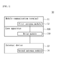
- FIG. 1 is a block diagram showing a communication system employing the embodiment.
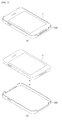
- FIG. 2 is a perspective view showing an example of a case apparatus according to the embodiments.
- FIG. 2 (a) shows the case apparatus mounted on a mobile communication terminal
- FIG. 2 (b) shows the case apparatus detached from the mobile communication terminal.
- the communication system 10 employing the embodiment includes a mobile communication terminal 11, an external device 13, and a case apparatus 100.
- the mobile communication terminal 11 and the external device 13 may perform a near field communication. That is, since the mobile communication terminal 11 accesses the external device 13, the mobile communication terminal 11 and the external device may perform the near field communication.
- the near field communication may include NFC (Near Field Communication).
- the mobile communication terminal 11 may include a first antenna module 12 and the external device 13 may include a second antenna module 14. Accordingly, when the mobile communication terminal 11 accesses the external device 13, the first antenna module 12 and the second antenna module 14 may perform the near field communication.
- the mobile communication terminal 11 may include a smart card, a portable phone, a smart phone, a netbook, a notebook, etc.
- the external device 13 may be various electronic devices including a reader.
- the case apparatus 100 is mountable on the mobile communication terminal 11. In other words, the case apparatus 100 may be mounted to and detached from the mobile communication terminal 11. In this case, the case apparatus 100 may be mounted on the mobile communication terminal 11 to protect the mobile communication terminal 11 and improve the appearance of the mobile communication terminal 11.
- the case apparatus 100 may be mounted on the mobile communication terminal 11 to relay the near field communication between the mobile communication terminal 11 and the external device 13.
- the case apparatus 100 may receive a signal from the mobile communication terminal 11 and transfer the signal to the external device 13.
- the case apparatus 100 may receive the signal from the external device 13 and transfer the signal to the mobile communication terminal 11.
- the case apparatus 100 may include a relay module 110. Accordingly, when the mobile communication terminal 11 accesses the external device 13, the relay module 110 may relay the near field communication between the first antenna module 12 and the second antenna module 14.
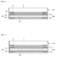
- FIG. 3 is a sectional view showing a case apparatus according to the first embodiment.
- FIG. 4 is a perspective view showing a relay module of FIG. 3 .
- the case apparatus 100 of the embodiment includes the relay module 110, a shielding member 120 and a protective part 130.
- the relay module 110 relays the signal in the case apparatus 100. That is, the relay module 110 relays the near field communication between the mobile communication terminal 11 and the external device 13. In detail, the relay module 110 performs the near field communication with the mobile communication terminal 11, and performs the near field communication with the external device 13. In this case, the relay module 110 may receive a signal from the mobile communication terminal 11 and transfer the signal to the external device 13. In addition, the relay module 110 may receive the signal from the external device 13 and transfer the signal to the mobile communication terminal 11. In this case, the near field communication may include NFC (Near Field Communication).
- the relay module 110 includes antenna elements 111 and 113.
- the relay module 110 includes first and second antenna elements 111 and 113.
- the first and second antenna elements 111 and 113 may be connected to each other. That is, the relay module 110 may be folded at the center thereof.
- the first antenna element 111 faces the mobile communication terminal 11 in the case apparatus 100.
- the first antenna element 111 may perform the near field communication with the mobile communication terminal 11. That is, the antenna element 111 exchanges the signal with the mobile communication terminal 11.
- the first antenna element 111 receives the signal from the first antenna module 12 or transfers the signal to the first antenna module 12.
- the first antenna 113 is disposed opposite the first antenna element 111 in the case apparatus 100.
- the second antenna element 113 may perform the near field communication with the external device 13. That is, the second antenna element 113 exchanges the signal with the external device 13. In this case, the second antenna element 113 receives the signal from the second antenna module 14 or transfers the signal to the second antenna module 14.
- the first and second antenna elements 111 and 113 may be formed as shown in FIG. 4 . That is, each of the first and second antenna elements 111 and 113 may include a coil. In this case, both ends of the first and second antenna elements 111 and 113 may be mutually connected. In addition, the first and second antenna elements 111 and 113 may form a loop. Selectively, any one of the first and second antenna elements 111 and 113 may further include a reactance element 115.
- the reactance element 115 may include an induction element and a capacitance element.
- the induction element may include an inductor and the capacitance element may include a capacitor.
- the shielding member 120 shields the antenna elements 111 and 113 in the case apparatus 100.
- the shielding member 120 is interposed between the antenna elements 111 and 113.
- the shielding member 120 may separate the antenna elements 111 and 113 from each other.
- the shielding member 120 may be formed in a single layer structure, or may be formed in a multi-layer structure. Accordingly, the second antenna element 113 is disposed opposite the first antenna element 111, with the shielding member 120 provided therebetween.
- the shielding member 120 may be realized by a ferrite.
- the shielding member 120 may include metallic particles and a resin material.
- the metallic particles may include soft magnetic metallic particles, for example, metal silicon and iron oxide ((FeO; Fe3O4; Fe2O3).
- the resin material may include a thermoplastic resin, for example, polyolefin elastomer.
- the protective part 130 is mountable on the mobile communication terminal 11 in the case apparatus 100. In other words, the protective part 130 may be mounted on and detached from the mobile communication terminal 11. In this case, the protective part 130 may adhere to the mobile communication terminal 11. In this case, the protective part 130 may extend toward a side surface of the mobile communication terminal 11, however not limited thereto.
- the protective part 130 may be formed by a plastic material.
- the protective part 130 encapsulates the antenna elements 111 and 113 and the shielding member 120 in the case apparatus 100.
- the protective part 130 couples the antenna elements 111 and 113 and the shielding member 120 in the case apparatus 100.
- an accommodating space is formed in the protective part 130.
- the protective part 130 accommodates the antenna elements 111 and 113 and the shielding member 120 in the case apparatus 100.
- the case apparatus 100 may be mounted on the mobile communication terminal 11 to protect the mobile communication terminal 11 and improve the appearance of the mobile communication terminal 11.
- a relay module 120 of the case apparatus may relay the near field communication between the mobile communication terminal 11 and the external device 13.
- the relay module may relay the signal transceived by the mobile communication terminal 11. Accordingly, even when the case apparatus 100 is mounted on the mobile communication terminal 11, the near field communication between the mobile communication terminal 11 and the external device 13 may be smoothly performed. Accordingly, the case apparatus 100 may prevent the performance of the mobile communication terminal 11 from degradation.
- FIG. 5 is a sectional view showing a case apparatus according to the second embodiment.
- the case apparatus 100 of the embodiment includes the relay module 110, the shielding member 120, the protective part 130 and a correction member 140.
- the relay module 100, the shielding member 120 and the protective part 130 are identical to the described embodiment, so the description will be omitted.
- the shielding member 120 is formed in a multilayer structure.
- the shielding member 120 includes multiple shielding sheets 121 and 123.
- the shielding member 120 includes first and second shielding sheets 121 and 123.
- the first shielding sheet 121 is attached to the first antenna element 111.
- the second shielding sheet 123 is attached to the second antenna elements 113.
- the first and second shielding sheets 121 and 123 may be formed by similar materials.
- the first and second shielding sheets 121 and 123 may be connected to each other. That is, the shielding sheet 120 may be folded at the center thereof.
- the correction member 140 maintains the shape of the case apparatus 100.
- the correction member 140 is interposed between the shielding members 121 and 123.
- the correction member 140 may separate the shielding members 121 and 123 from each other.
- the correction member 140 may separate the antenna elements 111 and 113 from each other.
- the correction member 140 may be formed as a single layer structure, or may be formed as a multi-layer structure. Accordingly, the second shielding sheet 123 is disposed at an opposite side of the correction member 140 from the first antenna element 121. In other words, the second antenna element 113 is disposed opposite the first antenna element 111, with the shielding member 140 provided therebetween.
- the case apparatus 100 may be mounted on the mobile communication terminal 11 to protect the mobile communication terminal 11 and improve the appearance of the mobile communication terminal 11.
- the correction member 140 of the case apparatus 100 may more effectively protect the mobile communication terminal 11.
- a relay module 120 of the case apparatus may relay the near field communication between the mobile communication terminal 11 and the external device 13.
- the relay module may relay the signal transceived by the mobile communication terminal 11. Accordingly, even when the case apparatus 100 is mounted on the mobile communication terminal 11, the near field communication between the mobile communication terminal 11 and the external device 13 may be smoothly performed. Accordingly, the case apparatus 100 may prevent the performance of the mobile communication terminal 11 from degradation.
- FIG. 6 is a sectional view showing a case apparatus according to the third embodiment.
- the case apparatus 100 of the embodiment includes the relay module 110, the shielding member 120, the protective part 130 and a battery 150.
- the relay module 100 since the shielding member 120 and the protective part 130 are identical to those of the described embodiment, the details thereof will be omitted.
- the battery 150 supplies power to the mobile communication terminal 11 in the case apparatus 100.
- the battery 150 includes an output terminal (not shown) and an input terminal (not shown).
- a connection terminal connects to the mobile communication terminal 11 to output power of the battery to the mobile communication terminal 11.
- the input terminal connects to an external power source to input power of the external power source to the battery 150. In this case, even though not shown, the connection terminal and the input terminal are externally exposed by the protective part 130.
- the battery 150 maintains the shape of the case apparatus 100.
- the battery 150 is interposed between the shielding members 121 and 123.
- the battery 150 may separate the shielding members 121 and 123 from each other.
- the battery 150 may separate the antenna elements 111 and 113 from each other.
- the second shielding sheet 123 is disposed opposite the first antenna element 121, with the battery 150 provided therebetween.
- the second antenna element 113 is disposed opposite the first antenna element 111, with the battery 150 provided therebetween.
- the case apparatus 100 may be mounted on the mobile communication terminal 11 to protect the mobile communication terminal 11 and improve the appearance of the mobile communication terminal 11.
- the battery 150 of the case apparatus 100 may more effectively supply power to the mobile communication terminal 11.
- the relay module 120 of the case apparatus 100 may relay the near field communication between the mobile communication terminal 11 and the external device 13.
- the relay module may relay the signal transceived by the mobile communication terminal 11. Accordingly, even when the case apparatus 100 is mounted on the mobile communication terminal 11, the near field communication between the mobile communication terminal 11 and the external device 13 may be smoothly performed. Accordingly, the case apparatus 100 may prevent the performance of the mobile communication terminal 11 from degradation.
Landscapes
- Engineering & Computer Science (AREA)
- Computer Networks & Wireless Communication (AREA)
- Physics & Mathematics (AREA)
- Electromagnetism (AREA)
- Signal Processing (AREA)
- Telephone Set Structure (AREA)
Applications Claiming Priority (1)
| Application Number | Priority Date | Filing Date | Title |
|---|---|---|---|
| KR1020140051883A KR102152694B1 (ko) | 2014-04-29 | 2014-04-29 | 케이스 장치 |
Publications (2)
| Publication Number | Publication Date |
|---|---|
| EP2940792A1 true EP2940792A1 (fr) | 2015-11-04 |
| EP2940792B1 EP2940792B1 (fr) | 2019-03-13 |
Family
ID=53181054
Family Applications (1)
| Application Number | Title | Priority Date | Filing Date |
|---|---|---|---|
| EP15165428.2A Active EP2940792B1 (fr) | 2014-04-29 | 2015-04-28 | Appareil à boîtier |
Country Status (4)
| Country | Link |
|---|---|
| US (1) | US9564943B2 (fr) |
| EP (1) | EP2940792B1 (fr) |
| KR (1) | KR102152694B1 (fr) |
| CN (2) | CN204697121U (fr) |
Cited By (2)
| Publication number | Priority date | Publication date | Assignee | Title |
|---|---|---|---|---|
| WO2017174900A1 (fr) * | 2016-04-08 | 2017-10-12 | Khamprasith Bounpraseuth | Boite pour terminal de communication mobile |
| FR3058837A1 (fr) * | 2016-11-17 | 2018-05-18 | Khamprasith Bounpraseuth | Boite pour terminal de communication mobile |
Families Citing this family (4)
| Publication number | Priority date | Publication date | Assignee | Title |
|---|---|---|---|---|
| JP6688507B2 (ja) * | 2017-03-30 | 2020-04-28 | 株式会社ユピテル | 中継システム |
| WO2020073247A1 (fr) * | 2018-10-10 | 2020-04-16 | 西门子股份公司 | Système et modules de communication |
| WO2020145423A1 (fr) * | 2019-01-08 | 2020-07-16 | 주식회사 아이엠기술 | Boîtier de dispositif mobile et son procédé de revêtement |
| CN114389669B (zh) * | 2020-10-20 | 2023-04-07 | 上海华为技术有限公司 | 一种通信设备、通信增强装置及天线集成部件 |
Citations (4)
| Publication number | Priority date | Publication date | Assignee | Title |
|---|---|---|---|---|
| US20080297419A1 (en) * | 2007-05-31 | 2008-12-04 | Weiping Dou | High Isolation Antenna Design for Reducing Frequency Coexistence Interference |
| US20100113111A1 (en) * | 2008-11-06 | 2010-05-06 | Wong Alfred Y | Radiation Redirecting External Case For Portable Communication Device and Antenna Embedded In Battery of Portable Communication Device |
| US20110163457A1 (en) * | 2009-02-20 | 2011-07-07 | National Semiconductor Corporation | Integrated circuit micro-module |
| WO2013165421A1 (fr) * | 2012-05-03 | 2013-11-07 | Intel Corporation | Antenne modulaire pour intégration de couplage en champ proche dans des dispositifs à châssis métallique |
Family Cites Families (34)
| Publication number | Priority date | Publication date | Assignee | Title |
|---|---|---|---|---|
| JP3044966U (ja) | 1997-04-14 | 1998-01-23 | 株式会社デューク | 移動電話機用ループアンテナ |
| JP2000137779A (ja) | 1998-10-30 | 2000-05-16 | Hitachi Maxell Ltd | 非接触情報媒体とその製造方法 |
| JP3630006B2 (ja) * | 1999-03-18 | 2005-03-16 | サクサ株式会社 | 非接触型icカードホルダー |
| KR20000063118A (ko) | 1999-09-29 | 2000-11-06 | 정석화 | 휴대폰의 안테나 장치 |
| KR20020064451A (ko) | 2001-02-01 | 2002-08-09 | 유씨에스코리아주식회사 | 상호 유도 증폭 중계 안테나를 통한 비접촉 아이씨 카드시스템의 알에프 신호 증폭 방법 및 장치 |
| JP2003187195A (ja) | 2001-12-13 | 2003-07-04 | Sony Corp | 非接触通信システムおよび方法、並びに非接触通信カード |
| JP2003249814A (ja) | 2002-02-25 | 2003-09-05 | Tecdia Kk | 非接触rfidタグ用同調コンデンサ付きループアンテナ |
| JP4058300B2 (ja) | 2002-06-21 | 2008-03-05 | 株式会社日立製作所 | 携帯情報装置 |
| KR100682539B1 (ko) | 2002-07-16 | 2007-02-15 | 양순석 | 페라이트 시트를 가진 박편 안테나 코일 및 그 제조 방법 |
| JP2004227046A (ja) | 2003-01-20 | 2004-08-12 | Hitachi Ltd | 携帯情報機器 |
| JP2004343410A (ja) | 2003-05-15 | 2004-12-02 | Hitachi Maxell Ltd | 非接触通信式情報担体 |
| JP3982476B2 (ja) * | 2003-10-01 | 2007-09-26 | ソニー株式会社 | 通信システム |
| JP2005117354A (ja) | 2003-10-08 | 2005-04-28 | Nec Saitama Ltd | 携帯電話機及びそれに用いる電池パック並びに接続コネクタ |
| JP4649183B2 (ja) | 2004-11-30 | 2011-03-09 | 株式会社東芝 | 無線通信端末 |
| KR20060110579A (ko) | 2005-04-20 | 2006-10-25 | 주식회사 엘지화학 | Pcb 상에 패터닝된 루프 안테나를 포함하고 있는이차전지 |
| KR100733813B1 (ko) | 2005-07-26 | 2007-07-02 | 삼성전자주식회사 | 휴대용 무선단말기의 안테나 장치 |
| DE602007007068D1 (de) | 2006-04-05 | 2010-07-22 | Nxp Bv | Verfahren zur dynamischen Zuweisung von Kontakten einer Teilnehmer-Chipkarte in einem mobilen Endgerät sowie entsprechendes Programm und mobiles Endgerät |
| JP4239205B2 (ja) | 2006-06-08 | 2009-03-18 | ソニー・エリクソン・モバイルコミュニケーションズ株式会社 | 携帯通信端末装置 |
| JP4770655B2 (ja) | 2006-09-12 | 2011-09-14 | 株式会社村田製作所 | 無線icデバイス |
| DE112007002024B4 (de) | 2006-09-26 | 2010-06-10 | Murata Mfg. Co., Ltd., Nagaokakyo-shi | Induktiv gekoppeltes Modul und Element mit induktiv gekoppeltem Modul |
| JP2008251283A (ja) | 2007-03-29 | 2008-10-16 | Kyocera Corp | 電子機器及び二次電池 |
| CN201038309Y (zh) | 2007-04-04 | 2008-03-19 | 浙江正原电气股份有限公司 | 一种ltcc多层陶瓷天线 |
| JP4955465B2 (ja) | 2007-06-11 | 2012-06-20 | 株式会社タムラ製作所 | ブースターアンテナ |
| US9172134B2 (en) * | 2008-11-06 | 2015-10-27 | Antenna79, Inc. | Protective cover for a wireless device |
| US8957813B2 (en) * | 2009-03-13 | 2015-02-17 | Pong Research Corporation | External case for redistribution of RF radiation away from wireless communication device user and wireless communication device incorporating RF radiation redistribution elements |
| US8214003B2 (en) * | 2009-03-13 | 2012-07-03 | Pong Research Corporation | RF radiation redirection away from portable communication device user |
| KR101052115B1 (ko) * | 2009-06-10 | 2011-07-26 | 엘지이노텍 주식회사 | 이중 공진을 이용한 nfc 안테나 |
| JP5135450B2 (ja) * | 2010-03-31 | 2013-02-06 | デクセリアルズ株式会社 | アンテナ装置、通信装置 |
| KR20130027433A (ko) * | 2011-09-07 | 2013-03-15 | 안병학 | 이동 단말기 악세서리 |
| KR20130045038A (ko) * | 2011-10-25 | 2013-05-03 | 봉민 | 보조배터리 케이스 |
| KR101191356B1 (ko) * | 2012-08-01 | 2012-10-15 | (주)에프원테크놀로지 | Led 발광부를 구비한 휴대형 단말기 보호케이스 |
| US9247681B2 (en) * | 2013-03-28 | 2016-01-26 | Blackberry Limited | Electric shielding enclosure including power pack |
| WO2015003034A1 (fr) * | 2013-07-03 | 2015-01-08 | Bluflux Technologies, Llc | Boîtier de dispositif électronique ayant une antenne |
| US9264090B2 (en) * | 2014-01-07 | 2016-02-16 | Otter Products, Llc | Metallic protective case for electronic device |
-
2014
- 2014-04-29 KR KR1020140051883A patent/KR102152694B1/ko active Active
-
2015
- 2015-04-28 US US14/698,446 patent/US9564943B2/en active Active
- 2015-04-28 EP EP15165428.2A patent/EP2940792B1/fr active Active
- 2015-04-29 CN CN201520269164.4U patent/CN204697121U/zh not_active Expired - Lifetime
- 2015-04-29 CN CN201510213879.2A patent/CN105049552B/zh active Active
Patent Citations (4)
| Publication number | Priority date | Publication date | Assignee | Title |
|---|---|---|---|---|
| US20080297419A1 (en) * | 2007-05-31 | 2008-12-04 | Weiping Dou | High Isolation Antenna Design for Reducing Frequency Coexistence Interference |
| US20100113111A1 (en) * | 2008-11-06 | 2010-05-06 | Wong Alfred Y | Radiation Redirecting External Case For Portable Communication Device and Antenna Embedded In Battery of Portable Communication Device |
| US20110163457A1 (en) * | 2009-02-20 | 2011-07-07 | National Semiconductor Corporation | Integrated circuit micro-module |
| WO2013165421A1 (fr) * | 2012-05-03 | 2013-11-07 | Intel Corporation | Antenne modulaire pour intégration de couplage en champ proche dans des dispositifs à châssis métallique |
Cited By (2)
| Publication number | Priority date | Publication date | Assignee | Title |
|---|---|---|---|---|
| WO2017174900A1 (fr) * | 2016-04-08 | 2017-10-12 | Khamprasith Bounpraseuth | Boite pour terminal de communication mobile |
| FR3058837A1 (fr) * | 2016-11-17 | 2018-05-18 | Khamprasith Bounpraseuth | Boite pour terminal de communication mobile |
Also Published As
| Publication number | Publication date |
|---|---|
| CN105049552B (zh) | 2019-08-13 |
| US20150311942A1 (en) | 2015-10-29 |
| CN105049552A (zh) | 2015-11-11 |
| EP2940792B1 (fr) | 2019-03-13 |
| CN204697121U (zh) | 2015-10-07 |
| US9564943B2 (en) | 2017-02-07 |
| KR102152694B1 (ko) | 2020-09-07 |
| KR20150124823A (ko) | 2015-11-06 |
Similar Documents
| Publication | Publication Date | Title |
|---|---|---|
| US9564943B2 (en) | Case apparatus | |
| US10014577B2 (en) | Aerial module and mobile terminal device | |
| KR102017621B1 (ko) | 무선 충전용 코일 기판 및 이를 구비하는 전자 기기 | |
| KR101865540B1 (ko) | 무선 충전 모듈 및 이를 포함하는 휴대용 보조배터리 | |
| EP2992776B1 (fr) | Boîtier et appareil le comprenant | |
| US9502753B2 (en) | Communication terminal device | |
| US9515513B2 (en) | Mobile device and combo coil module | |
| US20160380338A1 (en) | Antenna device and electronic apparatus including antenna device | |
| US9614385B2 (en) | Apparatus and method for full-orientation over-the-air charging in portable electronic devices | |
| US20140145906A1 (en) | Antenna device and wireless communication device | |
| US20130335284A1 (en) | Edge-emitting antennas for ultra slim wireless mobile devices | |
| JP2015149833A (ja) | 電子機器 | |
| US10186875B2 (en) | Coil type unit for wireless power transmission, wireless power transmission device, electronic device and manufacturing method of coil type unit for wireless power transmission | |
| KR20140089192A (ko) | 무선 전력 수신 장치의 안테나용 연자성 시트, 연자성 플레이트 및 연자성 소결체 | |
| KR101843897B1 (ko) | 무선 충전과 nfc 통신을 위한 무선 안테나 및 이를 적용한 무선 단말기 | |
| US9628132B2 (en) | Case apparatus | |
| JP6612657B2 (ja) | 非接触充電用コイルアッシー | |
| KR101681412B1 (ko) | 케이스 및 이를 포함하는 기기 | |
| CN110301068A (zh) | 增强天线结构体、通信设备和机箱 | |
| WO2017154622A1 (fr) | Dispositif électronique | |
| KR101723843B1 (ko) | 휴대 단말기 | |
| TWI539659B (zh) | 雙線圈之天線結構 |
Legal Events
| Date | Code | Title | Description |
|---|---|---|---|
| PUAI | Public reference made under article 153(3) epc to a published international application that has entered the european phase |
Free format text: ORIGINAL CODE: 0009012 |
|
| AK | Designated contracting states |
Kind code of ref document: A1 Designated state(s): AL AT BE BG CH CY CZ DE DK EE ES FI FR GB GR HR HU IE IS IT LI LT LU LV MC MK MT NL NO PL PT RO RS SE SI SK SM TR |
|
| AX | Request for extension of the european patent |
Extension state: BA ME |
|
| 17P | Request for examination filed |
Effective date: 20151218 |
|
| RBV | Designated contracting states (corrected) |
Designated state(s): AL AT BE BG CH CY CZ DE DK EE ES FI FR GB GR HR HU IE IS IT LI LT LU LV MC MK MT NL NO PL PT RO RS SE SI SK SM TR |
|
| RAP1 | Party data changed (applicant data changed or rights of an application transferred) |
Owner name: LG INNOTEK CO., LTD. |
|
| STAA | Information on the status of an ep patent application or granted ep patent |
Free format text: STATUS: EXAMINATION IS IN PROGRESS |
|
| 17Q | First examination report despatched |
Effective date: 20180424 |
|
| GRAP | Despatch of communication of intention to grant a patent |
Free format text: ORIGINAL CODE: EPIDOSNIGR1 |
|
| STAA | Information on the status of an ep patent application or granted ep patent |
Free format text: STATUS: GRANT OF PATENT IS INTENDED |
|
| INTG | Intention to grant announced |
Effective date: 20181105 |
|
| RIN1 | Information on inventor provided before grant (corrected) |
Inventor name: LEEM, SUNG HYUN |
|
| GRAS | Grant fee paid |
Free format text: ORIGINAL CODE: EPIDOSNIGR3 |
|
| GRAA | (expected) grant |
Free format text: ORIGINAL CODE: 0009210 |
|
| STAA | Information on the status of an ep patent application or granted ep patent |
Free format text: STATUS: THE PATENT HAS BEEN GRANTED |
|
| AK | Designated contracting states |
Kind code of ref document: B1 Designated state(s): AL AT BE BG CH CY CZ DE DK EE ES FI FR GB GR HR HU IE IS IT LI LT LU LV MC MK MT NL NO PL PT RO RS SE SI SK SM TR |
|
| REG | Reference to a national code |
Ref country code: GB Ref legal event code: FG4D |
|
| REG | Reference to a national code |
Ref country code: CH Ref legal event code: EP Ref country code: AT Ref legal event code: REF Ref document number: 1108960 Country of ref document: AT Kind code of ref document: T Effective date: 20190315 |
|
| REG | Reference to a national code |
Ref country code: IE Ref legal event code: FG4D |
|
| REG | Reference to a national code |
Ref country code: DE Ref legal event code: R096 Ref document number: 602015026168 Country of ref document: DE |
|
| REG | Reference to a national code |
Ref country code: NL Ref legal event code: MP Effective date: 20190313 |
|
| REG | Reference to a national code |
Ref country code: LT Ref legal event code: MG4D |
|
| PG25 | Lapsed in a contracting state [announced via postgrant information from national office to epo] |
Ref country code: SE Free format text: LAPSE BECAUSE OF FAILURE TO SUBMIT A TRANSLATION OF THE DESCRIPTION OR TO PAY THE FEE WITHIN THE PRESCRIBED TIME-LIMIT Effective date: 20190313 Ref country code: NO Free format text: LAPSE BECAUSE OF FAILURE TO SUBMIT A TRANSLATION OF THE DESCRIPTION OR TO PAY THE FEE WITHIN THE PRESCRIBED TIME-LIMIT Effective date: 20190613 Ref country code: FI Free format text: LAPSE BECAUSE OF FAILURE TO SUBMIT A TRANSLATION OF THE DESCRIPTION OR TO PAY THE FEE WITHIN THE PRESCRIBED TIME-LIMIT Effective date: 20190313 Ref country code: LT Free format text: LAPSE BECAUSE OF FAILURE TO SUBMIT A TRANSLATION OF THE DESCRIPTION OR TO PAY THE FEE WITHIN THE PRESCRIBED TIME-LIMIT Effective date: 20190313 |
|
| PG25 | Lapsed in a contracting state [announced via postgrant information from national office to epo] |
Ref country code: GR Free format text: LAPSE BECAUSE OF FAILURE TO SUBMIT A TRANSLATION OF THE DESCRIPTION OR TO PAY THE FEE WITHIN THE PRESCRIBED TIME-LIMIT Effective date: 20190614 Ref country code: RS Free format text: LAPSE BECAUSE OF FAILURE TO SUBMIT A TRANSLATION OF THE DESCRIPTION OR TO PAY THE FEE WITHIN THE PRESCRIBED TIME-LIMIT Effective date: 20190313 Ref country code: HR Free format text: LAPSE BECAUSE OF FAILURE TO SUBMIT A TRANSLATION OF THE DESCRIPTION OR TO PAY THE FEE WITHIN THE PRESCRIBED TIME-LIMIT Effective date: 20190313 Ref country code: NL Free format text: LAPSE BECAUSE OF FAILURE TO SUBMIT A TRANSLATION OF THE DESCRIPTION OR TO PAY THE FEE WITHIN THE PRESCRIBED TIME-LIMIT Effective date: 20190313 Ref country code: LV Free format text: LAPSE BECAUSE OF FAILURE TO SUBMIT A TRANSLATION OF THE DESCRIPTION OR TO PAY THE FEE WITHIN THE PRESCRIBED TIME-LIMIT Effective date: 20190313 Ref country code: BG Free format text: LAPSE BECAUSE OF FAILURE TO SUBMIT A TRANSLATION OF THE DESCRIPTION OR TO PAY THE FEE WITHIN THE PRESCRIBED TIME-LIMIT Effective date: 20190613 |
|
| REG | Reference to a national code |
Ref country code: AT Ref legal event code: MK05 Ref document number: 1108960 Country of ref document: AT Kind code of ref document: T Effective date: 20190313 |
|
| PG25 | Lapsed in a contracting state [announced via postgrant information from national office to epo] |
Ref country code: AL Free format text: LAPSE BECAUSE OF FAILURE TO SUBMIT A TRANSLATION OF THE DESCRIPTION OR TO PAY THE FEE WITHIN THE PRESCRIBED TIME-LIMIT Effective date: 20190313 Ref country code: ES Free format text: LAPSE BECAUSE OF FAILURE TO SUBMIT A TRANSLATION OF THE DESCRIPTION OR TO PAY THE FEE WITHIN THE PRESCRIBED TIME-LIMIT Effective date: 20190313 Ref country code: RO Free format text: LAPSE BECAUSE OF FAILURE TO SUBMIT A TRANSLATION OF THE DESCRIPTION OR TO PAY THE FEE WITHIN THE PRESCRIBED TIME-LIMIT Effective date: 20190313 Ref country code: IT Free format text: LAPSE BECAUSE OF FAILURE TO SUBMIT A TRANSLATION OF THE DESCRIPTION OR TO PAY THE FEE WITHIN THE PRESCRIBED TIME-LIMIT Effective date: 20190313 Ref country code: CZ Free format text: LAPSE BECAUSE OF FAILURE TO SUBMIT A TRANSLATION OF THE DESCRIPTION OR TO PAY THE FEE WITHIN THE PRESCRIBED TIME-LIMIT Effective date: 20190313 Ref country code: EE Free format text: LAPSE BECAUSE OF FAILURE TO SUBMIT A TRANSLATION OF THE DESCRIPTION OR TO PAY THE FEE WITHIN THE PRESCRIBED TIME-LIMIT Effective date: 20190313 Ref country code: PT Free format text: LAPSE BECAUSE OF FAILURE TO SUBMIT A TRANSLATION OF THE DESCRIPTION OR TO PAY THE FEE WITHIN THE PRESCRIBED TIME-LIMIT Effective date: 20190713 Ref country code: SK Free format text: LAPSE BECAUSE OF FAILURE TO SUBMIT A TRANSLATION OF THE DESCRIPTION OR TO PAY THE FEE WITHIN THE PRESCRIBED TIME-LIMIT Effective date: 20190313 |
|
| PG25 | Lapsed in a contracting state [announced via postgrant information from national office to epo] |
Ref country code: PL Free format text: LAPSE BECAUSE OF FAILURE TO SUBMIT A TRANSLATION OF THE DESCRIPTION OR TO PAY THE FEE WITHIN THE PRESCRIBED TIME-LIMIT Effective date: 20190313 Ref country code: SM Free format text: LAPSE BECAUSE OF FAILURE TO SUBMIT A TRANSLATION OF THE DESCRIPTION OR TO PAY THE FEE WITHIN THE PRESCRIBED TIME-LIMIT Effective date: 20190313 |
|
| REG | Reference to a national code |
Ref country code: CH Ref legal event code: PL |
|
| REG | Reference to a national code |
Ref country code: DE Ref legal event code: R097 Ref document number: 602015026168 Country of ref document: DE |
|
| REG | Reference to a national code |
Ref country code: BE Ref legal event code: MM Effective date: 20190430 |
|
| PG25 | Lapsed in a contracting state [announced via postgrant information from national office to epo] |
Ref country code: IS Free format text: LAPSE BECAUSE OF FAILURE TO SUBMIT A TRANSLATION OF THE DESCRIPTION OR TO PAY THE FEE WITHIN THE PRESCRIBED TIME-LIMIT Effective date: 20190713 Ref country code: LU Free format text: LAPSE BECAUSE OF NON-PAYMENT OF DUE FEES Effective date: 20190428 Ref country code: AT Free format text: LAPSE BECAUSE OF FAILURE TO SUBMIT A TRANSLATION OF THE DESCRIPTION OR TO PAY THE FEE WITHIN THE PRESCRIBED TIME-LIMIT Effective date: 20190313 |
|
| PLBE | No opposition filed within time limit |
Free format text: ORIGINAL CODE: 0009261 |
|
| STAA | Information on the status of an ep patent application or granted ep patent |
Free format text: STATUS: NO OPPOSITION FILED WITHIN TIME LIMIT |
|
| PG25 | Lapsed in a contracting state [announced via postgrant information from national office to epo] |
Ref country code: MC Free format text: LAPSE BECAUSE OF FAILURE TO SUBMIT A TRANSLATION OF THE DESCRIPTION OR TO PAY THE FEE WITHIN THE PRESCRIBED TIME-LIMIT Effective date: 20190313 Ref country code: LI Free format text: LAPSE BECAUSE OF NON-PAYMENT OF DUE FEES Effective date: 20190430 Ref country code: DK Free format text: LAPSE BECAUSE OF FAILURE TO SUBMIT A TRANSLATION OF THE DESCRIPTION OR TO PAY THE FEE WITHIN THE PRESCRIBED TIME-LIMIT Effective date: 20190313 Ref country code: CH Free format text: LAPSE BECAUSE OF NON-PAYMENT OF DUE FEES Effective date: 20190430 |
|
| 26N | No opposition filed |
Effective date: 20191216 |
|
| GBPC | Gb: european patent ceased through non-payment of renewal fee |
Effective date: 20190613 |
|
| PG25 | Lapsed in a contracting state [announced via postgrant information from national office to epo] |
Ref country code: SI Free format text: LAPSE BECAUSE OF FAILURE TO SUBMIT A TRANSLATION OF THE DESCRIPTION OR TO PAY THE FEE WITHIN THE PRESCRIBED TIME-LIMIT Effective date: 20190313 Ref country code: BE Free format text: LAPSE BECAUSE OF NON-PAYMENT OF DUE FEES Effective date: 20190430 |
|
| PG25 | Lapsed in a contracting state [announced via postgrant information from national office to epo] |
Ref country code: TR Free format text: LAPSE BECAUSE OF FAILURE TO SUBMIT A TRANSLATION OF THE DESCRIPTION OR TO PAY THE FEE WITHIN THE PRESCRIBED TIME-LIMIT Effective date: 20190313 |
|
| PG25 | Lapsed in a contracting state [announced via postgrant information from national office to epo] |
Ref country code: GB Free format text: LAPSE BECAUSE OF NON-PAYMENT OF DUE FEES Effective date: 20190613 Ref country code: IE Free format text: LAPSE BECAUSE OF NON-PAYMENT OF DUE FEES Effective date: 20190428 |
|
| PG25 | Lapsed in a contracting state [announced via postgrant information from national office to epo] |
Ref country code: FR Free format text: LAPSE BECAUSE OF NON-PAYMENT OF DUE FEES Effective date: 20190513 |
|
| PG25 | Lapsed in a contracting state [announced via postgrant information from national office to epo] |
Ref country code: CY Free format text: LAPSE BECAUSE OF FAILURE TO SUBMIT A TRANSLATION OF THE DESCRIPTION OR TO PAY THE FEE WITHIN THE PRESCRIBED TIME-LIMIT Effective date: 20190313 |
|
| PG25 | Lapsed in a contracting state [announced via postgrant information from national office to epo] |
Ref country code: MT Free format text: LAPSE BECAUSE OF FAILURE TO SUBMIT A TRANSLATION OF THE DESCRIPTION OR TO PAY THE FEE WITHIN THE PRESCRIBED TIME-LIMIT Effective date: 20190313 Ref country code: HU Free format text: LAPSE BECAUSE OF FAILURE TO SUBMIT A TRANSLATION OF THE DESCRIPTION OR TO PAY THE FEE WITHIN THE PRESCRIBED TIME-LIMIT; INVALID AB INITIO Effective date: 20150428 |
|
| PG25 | Lapsed in a contracting state [announced via postgrant information from national office to epo] |
Ref country code: MK Free format text: LAPSE BECAUSE OF FAILURE TO SUBMIT A TRANSLATION OF THE DESCRIPTION OR TO PAY THE FEE WITHIN THE PRESCRIBED TIME-LIMIT Effective date: 20190313 |
|
| PGFP | Annual fee paid to national office [announced via postgrant information from national office to epo] |
Ref country code: DE Payment date: 20250320 Year of fee payment: 11 |