EP2940816A2 - Dispositif d'installation électrique pour montage encastré - Google Patents
Dispositif d'installation électrique pour montage encastré Download PDFInfo
- Publication number
- EP2940816A2 EP2940816A2 EP15305535.5A EP15305535A EP2940816A2 EP 2940816 A2 EP2940816 A2 EP 2940816A2 EP 15305535 A EP15305535 A EP 15305535A EP 2940816 A2 EP2940816 A2 EP 2940816A2
- Authority
- EP
- European Patent Office
- Prior art keywords
- flush
- installation device
- mounted box
- frame part
- contact surface
- Prior art date
- Legal status (The legal status is an assumption and is not a legal conclusion. Google has not performed a legal analysis and makes no representation as to the accuracy of the status listed.)
- Withdrawn
Links
- 238000009434 installation Methods 0.000 title claims abstract description 86
- 238000010616 electrical installation Methods 0.000 claims abstract description 20
- 238000000034 method Methods 0.000 claims abstract description 11
- 230000000295 complement effect Effects 0.000 claims abstract description 3
- 239000011505 plaster Substances 0.000 claims description 16
- 238000010276 construction Methods 0.000 description 1
- 230000001419 dependent effect Effects 0.000 description 1
- 238000005553 drilling Methods 0.000 description 1
- 238000012805 post-processing Methods 0.000 description 1
- 238000006467 substitution reaction Methods 0.000 description 1
Images



Classifications
-
- H—ELECTRICITY
- H02—GENERATION; CONVERSION OR DISTRIBUTION OF ELECTRIC POWER
- H02G—INSTALLATION OF ELECTRIC CABLES OR LINES, OR OF COMBINED OPTICAL AND ELECTRIC CABLES OR LINES
- H02G3/00—Installations of electric cables or lines or protective tubing therefor in or on buildings, equivalent structures or vehicles
- H02G3/02—Details
- H02G3/08—Distribution boxes; Connection or junction boxes
- H02G3/12—Distribution boxes; Connection or junction boxes for flush mounting
- H02G3/121—Distribution boxes; Connection or junction boxes for flush mounting in plain walls
-
- H—ELECTRICITY
- H02—GENERATION; CONVERSION OR DISTRIBUTION OF ELECTRIC POWER
- H02G—INSTALLATION OF ELECTRIC CABLES OR LINES, OR OF COMBINED OPTICAL AND ELECTRIC CABLES OR LINES
- H02G3/00—Installations of electric cables or lines or protective tubing therefor in or on buildings, equivalent structures or vehicles
- H02G3/02—Details
- H02G3/08—Distribution boxes; Connection or junction boxes
- H02G3/081—Bases, casings or covers
- H02G3/083—Inlets
-
- H—ELECTRICITY
- H02—GENERATION; CONVERSION OR DISTRIBUTION OF ELECTRIC POWER
- H02G—INSTALLATION OF ELECTRIC CABLES OR LINES, OR OF COMBINED OPTICAL AND ELECTRIC CABLES OR LINES
- H02G3/00—Installations of electric cables or lines or protective tubing therefor in or on buildings, equivalent structures or vehicles
- H02G3/02—Details
- H02G3/08—Distribution boxes; Connection or junction boxes
- H02G3/14—Fastening of cover or lid to box
Definitions
- the invention relates to an electrical installation device for flush-mounted installation in a component, preferably for installation in a wall, further preferably for installation in a shell wall.
- Flush-mounted boxes of an installation device are usually installed before the application of a plaster layer in the shell wall and assembled the installation device after applying the plaster layer. This makes it difficult to precisely determine the intended location of the installation device with respect to the plastered wall, in particular the depth with respect to the plastered wall, when attaching the flush-mounted box to the shell wall. This procedure usually requires a costly post-processing in order to achieve a good appearance with flush installation of the installation device.
- the German Utility Model DE 20 2005 001 010 U1 discloses a flush-mounted box for the installation of electrical equipment. It comprises a one-piece body, which is fixed in a wall before plastering. Then the wall is plastered to a predetermined thickness of the flush box. After plastering, the electrical device is installed in the flush-mounted box.
- the installation device comprises at least one flush-mounted box with an outer side and a first contact surface arranged on the outer side, a frame part with a second contact surface which at least partially forms a complementary surface to the first contact surface, and a mounting direction, wherein the first contact surface by a movement of Flush-mounted box in installation direction with the second contact surface in Berühning can be brought.
- the installation device may be a socket, a switch, a control, a display element or the like.
- the installation device may also be a combination of several of the aforementioned elements, such as a socket-switch combination.
- the flush box is a standard component.
- the flush-mounted box is a flush-mounted box according to DIN 49073.
- the first contact surface and the second contact surface are at least partially approximately parallel to each other.
- first contact surface and the second contact surface extend at least partially approximately parallel to a conical surface and / or a sphere.
- first contact surface and the second contact surface at least in sections in a parallel to the direction of installation cross-section can be stepped and or wavy.
- the first contact surface and the second contact surface are substantially oblique to the direction of installation.
- the flush-mounted box can be securely connected in a simple manner positively to the frame part.
- the frame part preferably has at least one opening through which the flush-mounted box can be pushed at least partially in the direction of installation in order to bring the first contact surface into contact with the second contact surface, wherein the opening is at least partially approximately circular and / or at least partially approximately circular-arc-shaped ,
- the flush-mounted box is set in its intended position transversely to the direction of installation.
- the flush-mounted box has at least one fastening element
- the installation device comprises at least one retaining element with a holding surface and wherein the retaining element can be fastened to the fastening element and the retaining surface can be applied to the frame part to secure the flush-mounted box against the installation direction in a form-fitting manner to keep.
- the flush-mounted box can be held by the retaining element counter to the installation direction non-positively on the frame part.
- the flush-mounted box is securely connected to the frame part.
- the fastening element is formed by a projecting from the outside in the radial direction to the outside projection.
- the projection may be designed to be connected to a projection of another flush-mounted box.
- an installation device with a combination, for example, a switch and a socket for installation next to each other in the component connected and aligned.
- the opening has at least one first recess, through which the projection can be pushed through in the installation direction.
- the flush-mounted box comprises at least one shoulder, which protrudes from the outside in the radial direction to the outside
- the opening has at least one second recess, in which the shoulder is received when the first bearing surface is in Berühning with the second bearing surface.
- the flush-mounted box can be aligned in a simple manner by the paragraph is aligned with the second recess.
- the frame part comprises a base portion which extends substantially transversely to the installation direction, wherein preferably the opening is arranged in the base portion.
- the holding surface to an underside of the base portion preferably adjacent to the first recess, can be applied to hold the flush-mounted box against the installation direction positively.
- the frame part preferably comprises a plastering section which runs essentially parallel to the installation direction, wherein preferably the plastering section forms an edge section which lies substantially in a plane extending transversely to the installation direction
- This embodiment allows a simple and safe application of the plaster layer on the component, so that the plaster layer can be applied to the surface-mounted portion in the radial direction in the desired width and up to the edge portion in the direction of installation in the desired depth.
- the installation device is characterized by a second flush-mounted box, which is connected to the flush-mounted box, wherein preferably the second flush-mounted box has a projection which is connected to a projection of the flush-mounted box.
- connection of the flush-mounted box with the frame part by moving the flush-mounted box in the installation direction.
- the cavity is a blind hole.
- the cavity is introduced by drilling into the component.
- the flush-mounted box is positively connected to the frame part, so that the flush-mounted box is held against the installation direction on the frame part.
- the flush-mounted box is positively connected to the frame part by at least one retaining element is connected to a fastening element of the flush-mounted box.
- a plaster layer wherein preferably the plaster layer is applied circumferentially around a Anputzabêt of the frame part on the component, wherein further preferably the plaster layer in the installation direction up to an edge portion of the Anputzabitess is applied.
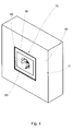
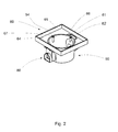
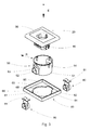
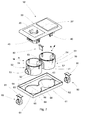
- FIGS. 1 to 4 show an installation device 10, which is mounted flush with the wall in a wall 70.
- the installation device 10 of the embodiment is designed as a socket 10.
- the socket 10 comprises a socket central piece 20, a design frame 30, a base part 40, a flush-mounted box 50 and a frame part 60.
- the socket 10 may additionally have a holding element 80.
- the holding element 80 comprises a holding surface 81.
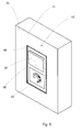
- FIGS. 5 to 8 show an installation device 10 'according to a second embodiment, which is also mounted flush with the wall 70 in the wall.
- the installation device 10 ' is as a socket-switch combination 10 'designed.
- the socket-switch combination 10 ' includes a socket center 20, a switch center 20' a design frame 30, two base parts 40, a first flush box 50, a second flush box 50 'and a frame part 60.
- the socket-switch combination 10' may additionally have a holding element 80.
- the holding element 80 comprises a holding surface 81.
- the socket-switch combination 10 ' may further comprise a support element 82 which is connected to the first flush-mounted box 50 and / or the second flush-mounted box 50' and supports the frame part 60.
- the flush-mounted box 50, 50 ' is preferably a flush-mounted box 50, 50' according to DIN 49073.
- the flush-mounted box 50, 50 ' comprises an outer side 51 and arranged on the outer side 51 first contact surface 52.
- the frame part 60 comprises a second contact surface 63.
- at least one shoulder 54 is provided on the outer side 51, which projects from the outer side 51 in a radial direction R to the outside.
- the frame part 60 has an opening 61.
- the opening 61 comprises at least one first recess 62, through which the projection 53 can be inserted through in the installation direction E when the first contact surface 52 is brought into contact with the second contact surface 63.
- the opening 61 further has at least one second recess 68, in which the shoulder 54 is received when the first bearing surface 52 with the second bearing surface 63 is in contact.
- the flush-mounted box 50, 50 ' is connected to the frame part 60 by moving the flush-mounted box 50, 50' through the opening 61 of the frame part 60 in an installation direction E until the first contact surface 52 is in contact with the second contact surface 62. In this case, the projection 53 is passed through the first recess 62. The heel 54 is received in the second recess 68.
- the flush-mounted box 50, 50 ' is positively connected to the frame part 60 such that it no longer moves in the installation direction E. can be.
- the flush-mounted box 50, 50 ' is thus positively connected to the frame part 60, that it is fixed in a direction transverse to the installation direction E radial direction R and against rotation about an axis which is parallel to the direction of installation E, fixed against rotation.
- the holding member 80 can be secured, for example by a clip connection.
- the holding surface 81 can be applied to the frame part 60, in particular on an underside 67 of the frame part, in order to hold the flush-mounted box 50 in a form-fitting manner against the installation direction E.
- the frame part 60 comprises a plastering section 65, which extends substantially parallel to the installation direction E and is approximately rectangular in cross section.
- the plastering section 65 protrudes from a base section 64 which lies in a plane extending transversely to the direction of installation E.
- the plastering section 65 comprises an edge section 66 which extends in a plane extending transversely to the installation direction E and is of approximately rectangular design.
- the plastering section 65 serves as a boundary up to which the plaster layer 71 is applied to the wall 70.
- the edge portion 66 serves as a reference to check whether the applied plaster layer 71 has the desired thickness.
- the socket 10 and the socket-switch combination 10 ' can be mounted flush with the wall 70 in a wall.
- the plaster layer is applied to the plastering section 65 on the wall 70 until the plaster layer 71 is the desired thickness and flush with the edge portion 66.
- the socket 10 can be assembled by the base part 40, the design frame 30, and the socket center 20 are installed in the flush-mounted box 50, 50 '.
Landscapes
- Engineering & Computer Science (AREA)
- Architecture (AREA)
- Civil Engineering (AREA)
- Structural Engineering (AREA)
- Connection Or Junction Boxes (AREA)
- Casings For Electric Apparatus (AREA)
- Switch Cases, Indication, And Locking (AREA)
Applications Claiming Priority (1)
| Application Number | Priority Date | Filing Date | Title |
|---|---|---|---|
| DE102014106026.1A DE102014106026B4 (de) | 2014-04-29 | 2014-04-29 | Elektrische Installationsvorrichtung für wandbündigen Einbau |
Publications (2)
| Publication Number | Publication Date |
|---|---|
| EP2940816A2 true EP2940816A2 (fr) | 2015-11-04 |
| EP2940816A3 EP2940816A3 (fr) | 2015-11-18 |
Family
ID=52997371
Family Applications (1)
| Application Number | Title | Priority Date | Filing Date |
|---|---|---|---|
| EP15305535.5A Withdrawn EP2940816A3 (fr) | 2014-04-29 | 2015-04-10 | Dispositif d'installation électrique pour montage encastré |
Country Status (2)
| Country | Link |
|---|---|
| EP (1) | EP2940816A3 (fr) |
| DE (2) | DE202014011151U1 (fr) |
Cited By (1)
| Publication number | Priority date | Publication date | Assignee | Title |
|---|---|---|---|---|
| NO20151795A1 (no) * | 2015-12-24 | 2017-06-26 | Selma Kristin Fredenborg | Innfelt stikkontaktpanel |
Citations (5)
| Publication number | Priority date | Publication date | Assignee | Title |
|---|---|---|---|---|
| DE1079715B (de) * | 1959-09-07 | 1960-04-14 | Fritz Wagner | Unterputzdose |
| DE1143884B (de) * | 1961-07-13 | 1963-02-21 | Berker Geb | Geraetedose fuer wasserdichte Unterputz-verlegung |
| DE2312605A1 (de) * | 1973-03-14 | 1974-09-19 | Paul Dahl | Zweiteilige installationsdose |
| DE202005001010U1 (de) | 2005-01-22 | 2005-03-31 | Pauls Werner | Unterputzdose |
| EP2650992A2 (fr) * | 2012-04-12 | 2013-10-16 | Legrand France | Chaussette d'étancheité pour appareillage électrique encastrable |
Family Cites Families (7)
| Publication number | Priority date | Publication date | Assignee | Title |
|---|---|---|---|---|
| DE1818761U (de) * | 1960-07-16 | 1960-09-29 | Hans Saegmueller | Abzweigdose. |
| NL6609690A (fr) * | 1966-06-16 | 1968-01-12 | ||
| DE2941905A1 (de) | 1979-10-17 | 1981-04-30 | Rudolf 7530 Pforzheim Mürle | Aus unter- und oberteil bestehendes unterputzgehaeuse zum einbau von elektrischen geraeten, wie schaltern, steckdosen o.dgl. |
| DE102009057940A1 (de) * | 2009-12-11 | 2011-06-16 | Abb Ag | Montagekonzept für Unterputz-Installationsmaterial |
| DE102011050048A1 (de) * | 2011-05-02 | 2012-11-08 | Dorma Gmbh + Co. Kg | Montageteil für aufputz-, unterputz- und/oder hohlraummontagefähige Einsätze |
| NL2008104C2 (nl) * | 2012-01-11 | 2013-07-15 | Abb Bv | Gietbouwdoos. |
| DE202014001918U1 (de) | 2013-04-26 | 2014-03-12 | Albrecht Jung Gmbh & Co. Kg | Installationsdose |
-
2014
- 2014-04-29 DE DE202014011151.0U patent/DE202014011151U1/de not_active Expired - Lifetime
- 2014-04-29 DE DE102014106026.1A patent/DE102014106026B4/de active Active
-
2015
- 2015-04-10 EP EP15305535.5A patent/EP2940816A3/fr not_active Withdrawn
Patent Citations (5)
| Publication number | Priority date | Publication date | Assignee | Title |
|---|---|---|---|---|
| DE1079715B (de) * | 1959-09-07 | 1960-04-14 | Fritz Wagner | Unterputzdose |
| DE1143884B (de) * | 1961-07-13 | 1963-02-21 | Berker Geb | Geraetedose fuer wasserdichte Unterputz-verlegung |
| DE2312605A1 (de) * | 1973-03-14 | 1974-09-19 | Paul Dahl | Zweiteilige installationsdose |
| DE202005001010U1 (de) | 2005-01-22 | 2005-03-31 | Pauls Werner | Unterputzdose |
| EP2650992A2 (fr) * | 2012-04-12 | 2013-10-16 | Legrand France | Chaussette d'étancheité pour appareillage électrique encastrable |
Cited By (1)
| Publication number | Priority date | Publication date | Assignee | Title |
|---|---|---|---|---|
| NO20151795A1 (no) * | 2015-12-24 | 2017-06-26 | Selma Kristin Fredenborg | Innfelt stikkontaktpanel |
Also Published As
| Publication number | Publication date |
|---|---|
| DE202014011151U1 (de) | 2018-02-27 |
| DE102014106026A1 (de) | 2015-10-29 |
| EP2940816A3 (fr) | 2015-11-18 |
| DE102014106026B4 (de) | 2018-04-26 |
Similar Documents
| Publication | Publication Date | Title |
|---|---|---|
| EP3114359B1 (fr) | Dispositif servant à assembler un élément de structure à un élément de maintien selon un espacement l'un par rapport à l'autre | |
| EP2738401A2 (fr) | Élément de montage rapide | |
| EP2824784A1 (fr) | Boîtier d'installation | |
| DE10303800B3 (de) | Einrichtung zur Befestigung eines Steckverbinderkontakteinsatzes in einem Steckverbindergehäuse | |
| EP2521233A2 (fr) | Pièce de montage pour inserts à montage en saillie, en encastrement et/ou en espace creux | |
| DE3432856C2 (fr) | ||
| DE202009013488U1 (de) | Vorrichtung zum Fixieren eines Baukörpers in einer Gebäudeöffnung | |
| EP3009692B1 (fr) | Element de meuble mobile et element de connexion | |
| DE102014106026B4 (de) | Elektrische Installationsvorrichtung für wandbündigen Einbau | |
| DE102018100360B4 (de) | Rosettengarnitur | |
| DE102014112308B4 (de) | Exzentereinheit und Verbinder | |
| WO2015091619A1 (fr) | Unité de montage de façade de tiroir | |
| DE102014118499B4 (de) | Schelle zur Befestigung einer Leitung, insbesondere stromführenden Leitung, an einem Schienenfahrzeug | |
| DE202016100339U1 (de) | Montagehalterung für ein Einbauelement und Set aus einer Montagehalterung und einem Einbauelement | |
| AT520742B1 (de) | Montagehilfe | |
| AT520816B1 (de) | Montagewinkel und Montageanordnung | |
| DE202007016981U1 (de) | Befestigungsvorrichtung für ein elektrotechnisches Bauteil | |
| DE102012211778A1 (de) | Beschlaganordnung | |
| EP2669457A1 (fr) | Unité de serrure et procédé de montage d'un actionneur de porte sur une plaque de montage d'une unité de serrure | |
| DE102007039171A1 (de) | Verfahren zur Montage bzw. zum Einbringen eines Hohlkörpers in eine Betonwand oder Betondecke | |
| DE202013001141U1 (de) | Erdungsmontagesystem | |
| EP2538507B1 (fr) | Adaptateur de barre collectrice | |
| EP3886280A1 (fr) | Système d'installation électrique | |
| DE102017119702A1 (de) | Hilfsvorrichtung zur Positionierung eines Haushaltsgerätes | |
| DE102015107496B3 (de) | Einputzadapter |
Legal Events
| Date | Code | Title | Description |
|---|---|---|---|
| PUAL | Search report despatched |
Free format text: ORIGINAL CODE: 0009013 |
|
| PUAI | Public reference made under article 153(3) epc to a published international application that has entered the european phase |
Free format text: ORIGINAL CODE: 0009012 |
|
| AK | Designated contracting states |
Kind code of ref document: A2 Designated state(s): AL AT BE BG CH CY CZ DE DK EE ES FI FR GB GR HR HU IE IS IT LI LT LU LV MC MK MT NL NO PL PT RO RS SE SI SK SM TR |
|
| AX | Request for extension of the european patent |
Extension state: BA ME |
|
| AK | Designated contracting states |
Kind code of ref document: A3 Designated state(s): AL AT BE BG CH CY CZ DE DK EE ES FI FR GB GR HR HU IE IS IT LI LT LU LV MC MK MT NL NO PL PT RO RS SE SI SK SM TR |
|
| AX | Request for extension of the european patent |
Extension state: BA ME |
|
| RIC1 | Information provided on ipc code assigned before grant |
Ipc: H02G 3/14 20060101ALN20151015BHEP Ipc: H02G 3/08 20060101ALN20151015BHEP Ipc: H02G 3/12 20060101AFI20151015BHEP |
|
| 17P | Request for examination filed |
Effective date: 20160512 |
|
| RBV | Designated contracting states (corrected) |
Designated state(s): AL AT BE BG CH CY CZ DE DK EE ES FI FR GB GR HR HU IE IS IT LI LT LU LV MC MK MT NL NO PL PT RO RS SE SI SK SM TR |
|
| 17Q | First examination report despatched |
Effective date: 20180131 |
|
| STAA | Information on the status of an ep patent application or granted ep patent |
Free format text: STATUS: THE APPLICATION IS DEEMED TO BE WITHDRAWN |
|
| 18D | Application deemed to be withdrawn |
Effective date: 20200623 |