EP2940974B1 - Handgerät zur dateneingabe sowie fernbedienungsgerät, mobiltelefon und spielgerät - Google Patents
Handgerät zur dateneingabe sowie fernbedienungsgerät, mobiltelefon und spielgerät Download PDFInfo
- Publication number
- EP2940974B1 EP2940974B1 EP14166403.7A EP14166403A EP2940974B1 EP 2940974 B1 EP2940974 B1 EP 2940974B1 EP 14166403 A EP14166403 A EP 14166403A EP 2940974 B1 EP2940974 B1 EP 2940974B1
- Authority
- EP
- European Patent Office
- Prior art keywords
- key
- handheld device
- input
- input key
- casing
- Prior art date
- Legal status (The legal status is an assumption and is not a legal conclusion. Google has not performed a legal analysis and makes no representation as to the accuracy of the status listed.)
- Not-in-force
Links
Images

Classifications
-
- H—ELECTRICITY
- H04—ELECTRIC COMMUNICATION TECHNIQUE
- H04M—TELEPHONIC COMMUNICATION
- H04M1/00—Substation equipment, e.g. for use by subscribers
- H04M1/02—Constructional features of telephone sets
- H04M1/23—Construction or mounting of dials or of equivalent devices; Means for facilitating the use thereof
- H04M1/236—Construction or mounting of dials or of equivalent devices; Means for facilitating the use thereof including keys on side or rear faces
-
- G—PHYSICS
- G06—COMPUTING OR CALCULATING; COUNTING
- G06F—ELECTRIC DIGITAL DATA PROCESSING
- G06F3/00—Input arrangements for transferring data to be processed into a form capable of being handled by the computer; Output arrangements for transferring data from processing unit to output unit, e.g. interface arrangements
- G06F3/01—Input arrangements or combined input and output arrangements for interaction between user and computer
- G06F3/02—Input arrangements using manually operated switches, e.g. using keyboards or dials
- G06F3/0202—Constructional details or processes of manufacture of the input device
- G06F3/0219—Special purpose keyboards
-
- G—PHYSICS
- G06—COMPUTING OR CALCULATING; COUNTING
- G06F—ELECTRIC DIGITAL DATA PROCESSING
- G06F3/00—Input arrangements for transferring data to be processed into a form capable of being handled by the computer; Output arrangements for transferring data from processing unit to output unit, e.g. interface arrangements
- G06F3/01—Input arrangements or combined input and output arrangements for interaction between user and computer
- G06F3/02—Input arrangements using manually operated switches, e.g. using keyboards or dials
- G06F3/023—Arrangements for converting discrete items of information into a coded form, e.g. arrangements for interpreting keyboard generated codes as alphanumeric codes, operand codes or instruction codes
- G06F3/0231—Cordless keyboards
-
- H—ELECTRICITY
- H01—ELECTRIC ELEMENTS
- H01H—ELECTRIC SWITCHES; RELAYS; SELECTORS; EMERGENCY PROTECTIVE DEVICES
- H01H9/00—Details of switching devices, not covered by groups H01H1/00 - H01H7/00
- H01H9/02—Bases, casings, or covers
- H01H9/0214—Hand-held casings
Definitions
- the invention relates to a handheld device for data input and a remote control device, a mobile phone and a game device, which have the handset.
- a mobile phone has, for example, a keyboard or a touchscreen with which telephone numbers, messages or data entries can be entered into the mobile phone.
- a remote control device for example, a TV or a stereo system has various program and function keys that are built as push buttons or membrane keys in the remote control device.
- the problem is that small size handset while handy in housing, but difficult to use and manual handling.
- the frequent and quick operation of the handset can cause tension in the hand, arm and neck of the operator. These tensions can affect mobility and cause pain, which may cause discomfort and even disability for the operator.
- the operator's psyche may also be impaired, which may influence the decisions of the operator when operating the hand-held device.
- the object of the invention is to provide a hand-held device for data input and a remote control device, a mobile phone and a game device that have the handset, with the devices allows a fast and convenient data entry is where the handset operator is relaxed and comfortable.
- the data input handset of the present invention comprises a data processing unit and a housing ergonomically shaped to be hand-shaped in a hand-held manner, and at least one input key coupled to the data processing unit for processing data input by the enter key and disposed on the housing such that, when the handset is held in the hand, of at least one of the four fingers or the thumb of the hand presses the enter key for data entry and thereby a pressing force from the finger or the thumb via the handset to the Hand surface is transferable, wherein a surface location of the housing, which is arranged away from the input key and to which, when the handset is held in the hand, immediately adjacent at least one of the reflection zones of the palm is arranged, with at least one of the surface site projecting stimulus projection ve is so that by pressing the enter button via the stimulus projection nerve end points of the reflex zone are irritated, is stimulated by the reflex zone associated body part during data entry.
- reflex zones On the palm are reflex zones, which are assigned for example to the solar plexus, the stomach, the liver or the lung.
- reflex zones On the fingertips are reflex zones, which are assigned to the front and head cavities, and at the thumb tip is a reflex zone, which is assigned to the brain. If the nerve end points of the reflex zones are stimulated during data entry, a beneficial and relaxing effect is established on the corresponding associated body parts, namely the solar plexus, the stomach, the frontal and the head cavities, the brain, the liver and the lungs.
- the well-being of the person performing the data entry with the handset of the invention is increased.
- the increase in well-being leads to an improvement in health and the mental state of the person.
- causesd by the well-being of the person caused by the data input by means of the hand-held device it can be inspired to far-reaching thoughts and ideas which can find a positive impression in the type and quality of the data entry.
- the housing preferably has at least one orientation nub associated with one of the roots of the fingers and arranged such that when the handset is held in the hand, the orientation nub engages its associated root and the stimulus projection is in touching contact with the reflex zone associated therewith can be brought and the input key of the finger / thumb assigned to it is pressed.
- the orientation knob is easy to engage with the root of the finger associated with it when the handset is held in the manner of the flatterer in the hand. Thereby, the arrangements of the input key relative to the fingers or the thumb and the stimulus projection are fixed relative to the reflex zone. Thus, the positioning of the input key relative to the fingers and the stimulus projection relative to the reflex zone are reproducible, whereby the handling of the handset is facilitated.
- the enter key / thumb key of the finger / thumb assigned to the enter key press the enter key.
- the fact that there are reflex zones for the forehead and head cavities at the fingertips and the reflex zone for the brain is located at the tip of the thumb pressing the enter button with the respective fingertip / thumb tip the corresponding reflex zone irritated.
- the housing has a housing opening in the surface location and the handset has a slidably mounted transmission pin coupled to the input key such that when the input key is depressed the transmission pin extends with its one longitudinal end through the housing opening and protrudes from the surface location, whereby the longitudinal end forms the stimulus projection.
- the transfer pin shifts out of the housing opening and protrudes with its one longitudinal end from the housing of the handset.
- the irritation of the transmission pin associated with the reflex zone adjustable.
- the one longitudinal end of the transfer pin is formed as a tip and the transfer pin is pressed out comparatively strong when pressing the input key, so that protrudes the one longitudinal end with a relatively large distance from the housing of the handset, sets a relatively strong irritation of the transmission pin associated with the reflex zone ,
- the transmission pin is dimensioned, supported and coupled to the input key such that, when the input key is not depressed, the longitudinal end of the transmission pin is sunk in the housing opening.
- an explicit stimulation of the reflex zone assigned to the transmission pin is not provided.
- the enter key preferably includes a slidable key top for depressing the enter key which is secured to the transfer pin in extension therefrom such that the key top together with the transfer pin completely penetrates the housing.
- a transmission gear for example in the form of a pivotally mounted lever with different length legs, is connected between the transmission pin and the input key, whereby the stroke of the input key is translatable to the stroke of the transmission pin.
- the key top preferably has a stimulus tip that protrudes from the housing, thereby irritating the finger / thumb when pressing the enter button. As a result, there is a strong irritation of the reflex zone at the fingertip / thumb tip.
- the input key has a slidable key top for pressing the input key and the transfer pin completely penetrates the housing and extends in the key top, so that when the input key is depressed, the longitudinal end of the transfer pin which faces away from the housing opening, through a key top opening of the key top and projecting from the key top, whereby the finger / thumb is irritated upon depression of the enter key. This drives the other longitudinal end of the transfer pin out of the keyhole opening and protrudes when pressing the Enter key from the key top.
- the transfer pin is supported by both the finger / thumb and the palm, whereby a strong irritation of the affected reflex zones is achieved. Furthermore, it is preferred that the transmission pin is telescopically movable while overcoming a resistance force, whereby the intensity of the irritation of the affected reflex zones can be adjusted by the strength of the resistance force.
- the handset further preferably comprises a biasing means which engages the key top and drives the key head in its non-pressed position with its biasing force counteracting the pressing force, wherein the biasing means is dimensioned such that the biasing force results in the magnitude of the compressive force that the reflex zone associated body part while data entry is stimulated for relaxation, pain relief or disease healing.
- the dimensioning of the biasing means is used to generate an individually selected stimulation for each affected reflex zone.
- the irritation can be personalized by the appropriate dimensioning of the biasing means. For example, if the biasing force is relatively strong, the irritation at the tip of the finger / thumb tip is comparatively low, whereas the irritation to the palm is comparatively large. A strong irritation is caused at the tip of the finger / thumb tip, when the biasing force is comparatively low, wherein depending on the pressure force, the irritation to the palm results.
- the transfer pin is bent shaped. It is further preferred that the transmission pin is bendable. Preferably, the transmission pin is longitudinally guided in the housing in a guide channel, so that, since the transmission pin is bent, a structurally simple bridging of the housing is made possible by the transmission pin.
- the handset has one of the input keys for each of the four fingers, and an additional input key for the thumb, which is formed as a multi-function key with which various functions of the input keys for the fingers are switchable. If the multifunction key can be switched to seven switching levels, for example, the four input keys can be used to display a maximum of 28 different characters. As a result, for example, the alphabet with the four input keys and the multifunction key would be displayed.
- the data processing unit preferably has a memory with which the data entered using the input keys can be stored. If the alphabet is displayed with the four input keys and the multifunction key, the handset can be used for text input. By appropriately selecting one of the seven switching levels of the multifunction key and the combined pressing of a matching one of the four input keys, a letter can be entered from the alphabet and stored in memory. If the person holds the handset in his hand and the hand is, for example, in a trouser pocket inserted, so can be done inconspicuously with the handset, the text input. At a later time and possibly in another location, the memory can be read out, for example, with a computer, whereby the text resulting from the text input is made accessible.
- the handset according to the invention is a remote control device for remote control of an apparatus, a mobile phone or a game device.
- the therapeutic effect of the hand reflex zone massage of the handset in the data input unfolds according to the invention in the handling of the remote control device, the mobile phone and the game device.
- Other applications of the hand-held device for data entry are conceivable.
- each reflex zones 114 are located for forehead and head cavities.
- a reflex zone 116 for the liver On the palm 101 in the region of the small finger 106, a reflex zone 116 for the liver, in the region of the middle finger 104 and the ring finger 105, a reflex zone 117 for the lungs and a reflex zone for the solar plexus 112 and in the region of the index finger 103, a reflex zone for the Stomach settled.
- a handset 1 comprises a housing 2 having an input key 3 for the thumb 102, an input key 4 for the index finger 103, an input key 4 for the middle finger 104, an input key 6 for the ring finger 105 and an input key 7 for the small finger 106 has. Further, the handset 1 has an orientation nub 8 for the root of the index finger 103, an orientation nub 9 for the root of the middle finger 104, an orientation nub 10 for the root of the ring finger 105 and an orientation nub 11 for the root of the small finger 106.
- the handset 1 has a stimulus projection 12, for the reflex zone 112 for the solar plexus, a stimulus projection 13, for the reflex zone 113 for the stomach, a stimulus projection 14 for the reflex zone 116 for the liver and a stimulus projection 15 for the reflex zone 117 for the lungs on.
- the input keys 3 to 7 are designed as pushbuttons. As projecting from the housing 2 and solid projections, the orientation nubs 8 to 11 and the stimulus projections 12 to 15 are formed.
- the housing 2 is ergonomically shaped for holding in the hand 101 in the manner of a flatterer and has the size of about a hen's egg.
- the orientation nubs 8 to 11 engage with the hand 101 with their respective finger roots 108, so that the hand-held device 1 can be easily gripped by the hand 101 with the fingers 102 to 106 and the palm 111.
- the input keys 3 to 7 are arranged relative to the orientation knobs 8 to 11 on the housing such that the input keys 3 to 7 are conveniently pressed by their associated fingers 103 to 106 and the thumb 102 with their respective fingertips 110 and thumb pad 109, respectively can.
- the stimulus projections 12 to 15 are relative to the orientation studs 8 to 11 on the housing 2 arranged such that, when the handset 1 is held in the hand 101, the stimulus projection 12, the reflex zone 112 for the solar plexus, the stimulus projection 13, the reflex zone 113 for the Stomach, the Stimulus projection 14 the reflex zone 114 for the liver and the stimulus projection 15 touches the reflex zone 115 for the lungs.
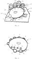
- FIGs 1 and 2 a first embodiment of the handset 1 is shown, in which the stimulus projections 12 to 15 are formed as local elevations on the housing 2.
- the input keys 3 to 7 are designed as pushbuttons.
- FIG. 3 a second embodiment of the handset 1 is shown.
- the configuration of the input keys 3 to 7 is shown by way of example on the input key 6 for the ring finger 105.
- the input key 6 has a key top 16, which is formed like a cylinder and is mounted longitudinally displaceably in a corresponding guide shaft 17 in the housing.
- the guide shaft 17 is oriented in the housing 2 such that when the key top 16 is pressed with the ring finger 105, the key top 16 in the guide shaft 17 is longitudinally displaced.
- the key top 16 is accessible from outside the housing 2 by the ring finger 105 in that the key top 16 protrudes with its one longitudinal end of the guide shaft 17 and thereby projects from the housing 2.
- a stimulus tip 18 is provided which is touched by the finger tip 110 of the ring finger 105 upon depression of the input key 6. Thereby, the reflex zone 114 for the forehead and head cavities on the ring finger 105 is stimulated.
- a transmission pin 19 is fixed, which is aligned with the key top 16 and extends to a housing opening 21 of the housing 2, the key head 16 together with the transfer pin 19, the housing 2 completely penetrates.
- the key head 16 is formed larger in diameter than the transfer pin 19, a step 20 is formed at the transition from the key top 16 to the transfer pin 19.
- the transfer pin 19 extends in particular when pressed the input button 6 with its longitudinal end 22, the The longitudinal end 22 projects from the housing 2 and forms the stimulus projection 16 for the reflex zone 115 for the lungs.
- the housing opening 21 is formed in a perforated disc 23, which is arranged in the housing 2 concentrically around the transfer pin 19.
- the perforated disc 23 corresponds to the step 20, wherein a first return spring 24 is supported on the step 20 and on the perforated disc 23 and arranged around the transfer pin 1.
- the spring force of the return spring 24 is opposite to the pressure force when pressing the input key 6.
- the fingertip 110 of the ring finger 105 touches the stimulus tip 18.
- the key head 16 moves together with the transfer pin 19 in the guide shaft 17, so that the key head 16 in the guide shaft 17th sunk more and more and the key head 16 facing away from longitudinal end 22 of the transfer pin 19 more and more out of the housing opening 21 protrudes. Since this longitudinal end 22 presses on the palm 111 and thus on the reflex zone 117 for the lungs, acts from the palm 11 a counter force on the transfer pin 19 and the key top 16, which is directed against the pressing force of the ring finger 105.
- FIG. 4 3 a third embodiment of the handset 1 is shown, by way of example the construction of the input key 4 for the index finger 103 is shown.
- the housing 2 has a pin channel 25 in which the Transmission pin 19 is mounted longitudinally displaceable, which extends completely through the housing 2.
- the housing opening 21 is a depressed input button 4, the one longitudinal end 22 of the transfer pin 19 in order to act as a stimulus projection 13 for the reflex zone 113 for the stomach.
- the key top 16 is arranged concentrically around the transfer pin 19, the key top 16 having a housing 2 remote from the key top cover 26.
- a key top opening 27 is provided, through which the other longitudinal end of the transfer pin 19, which is arranged facing away from the housing opening, is extendable.
- the guide shaft 17 accommodates the key top 16, which is larger in diameter than the transmission pin 19, and the transmission pin 19 is arranged in the pin channel 25, the transition from the pin channel 95 to the guide shaft 17 is stepped, whereby a base 29 is present.
- a second return spring 30 is supported on the base 29 and on the inside of the key top 26, so that a restoring force is exerted by the return spring 30 in a non-pressed position of the input key 4 on the key top 16.
- the key top 16 and the transfer pin 19 are freely displaceable to each other.
- the key top 16 When pressing the enter button 4 with the fingertip 110 of the index finger 103, the key top 16 is moved into the guide shaft 17, wherein the transfer pin 19 extends with its longitudinal end 28 through the key top opening 27 and protrudes from the key top 26.
- the reflex zone 114 is stimulated at the fingertip 110 of the index finger 103.
- the transfer pin 19 moves in the pin channel 25, so that the other longitudinal end 22 of the transfer pin 19 from the housing opening 21 more and more extended and the reflex zone 113 for the stomach is irritated.
- the protrusions of the transfer pin 19 at its longitudinal ends 22 and 28 and the friction between the transfer pin 19 and the pin channel 25 and / or the key top 16 and the guide shaft 17 is the degree of irritation of the reflex zone 114 at the fingertip and the reflex zone 113 the palm 111 adjustable.
- the input keys 3 to 7 are connected via signal lines 31 to a data processing unit 32.
- the data processing unit 32 has an input unit 33, with which the data input is controlled, and a memory 34, with which the input data is stored. To operate the data processing unit 32, this has a battery 35 for the power supply.
- the data processing unit 32 has an output unit 36 with which the data stored in the memory 34 can be read out to external devices via an output connection 37.
- the input key 3 is designed as a multi-function key with which seven positions can be switched with the thumb 102.
- the input unit 32 is set up such that, depending on the respective position of the input key 3, the input keys 4 to 7 are assigned to groups of letters of the alphabet.
- the handset 1 serves as a text input device, and with the fingers 103 to 106, input texts 4 to 7 corresponding to the operation of the input key with the thumb 102 can be inputted to texts stored in the storage unit 34 and the output unit 36 via the output port 37 can be read out again.
- the output unit 36 also have a Wlan module with the data via the Internet can be read.
- the handset 1 with its arrangement on the input keys 3 to 7 is constructed so symmetrical that the handset 1 is ambidextrous under the stimulation of the relevant reflex zones 112 to 117 operable, whereby the handset 1 is ambidextrous applicable, ie equivalent Both the right hand and the left hand can be held and operated while the handset 1 is suitable for both a right-handed and a left-hander.
Landscapes
- Engineering & Computer Science (AREA)
- General Engineering & Computer Science (AREA)
- Theoretical Computer Science (AREA)
- Human Computer Interaction (AREA)
- Physics & Mathematics (AREA)
- General Physics & Mathematics (AREA)
- Signal Processing (AREA)
- Push-Button Switches (AREA)
Description
- Die Erfindung betrifft ein Handgerät zur Dateneingabe sowie ein Fernbedienungsgerät, ein Mobiltelefon und ein Spielgerät, die das Handgerät aufweisen.
- Mobile elektronische Handgeräte zur Dateneingabe sind für diverse Anwendungen bekannt. Ein Mobiltelefon weist beispielsweise eine Tastatur oder einen Touchscreen auf, mit denen Telefonnummern, Mitteilungen oder Dateneintragungen in das Mobiltelefon eingegeben werden können. Ein Fernbedienungsgerät für beispielsweise einen Fernsehapparat oder eine Stereoanlage weist diverse Programm- und Funktionstasten auf, die als Drucktasten oder Folientasten in das Fernbedienungsgerät eingebaut sind. An die Handgeräte sind die Forderungen gestellt, dass sie möglichst klein, handlich und bequem bedienbar sein sollen. Problematisch ist jedoch, dass Handgeräte mit geringer Baugröße zwar handlich in der Unterbringung, jedoch schwierig in der Bedienung und der manuellen Handhabung sind. Außerdem ist es wünschenswert, dass Handgeräte für die menschliche Hand möglichst ergonomisch gestaltet sind, wobei die Beweglichkeit der Finger und des Daumens zu berücksichtigen sind. Bei der häufigen und schnellen Bedienung des Handgeräts kann es jedoch zu Verspannungen in der Hand, im Arm und im Nacken des Bedieners kommen. Diese Verspannungen können die Beweglichkeit beeinträchtigen und zu Schmerzen führen, wodurch sich ein Unwohlsein und sogar ein Handicap beim Bediener einstellen kann. Dadurch kann neben der körperlichen Gesundheit auch die Psyche des Bedieners beeinträchtigt sein, wodurch eventuell Entscheidungen des Bedieners bei der Bedienung des Handgeräts beeinflusst werden können.
-
DE 10 2004 042 884 A1 beschreibt ein Kommunikationsgerät für taubblinde Personen zur Übermittlung und zum Empfang von Informationen.US 6,762,749 B1 beschreibt ein elektronisches Datenanzeigesystem.WO 89/03569 - Aufgabe der Erfindung ist es, ein Handgerät zur Dateneingabe sowie ein Fernbedienungsgerät, ein Mobiltelefon und ein Spielgerät, die das Handgerät aufweisen, zu schaffen, wobei mit den Geräten eine schnelle und bequeme Dateneingabe ermöglicht ist, bei der die das Handgerät bedienende Person entspannt ist und sich wohl fühlt.
- Das erfindungsgemäße Handgerät zur Dateneingabe weist eine Datenverarbeitungseinheit und ein Gehäuse, das ergonomisch zum in einer Hand halten in der Art eines Handschmeichlers an die Hand angepasst geformt ist, sowie mindestens eine Eingabetaste auf, die mit der Datenverarbeitungseinheit zur Verarbeitung der Dateneingabe durch die Eingabetaste gekoppelt ist und derart an dem Gehäuse angeordnet ist, dass, wenn das Handgerät in der Hand gehalten ist, von mindestens einem der vier Finger oder dem Daumen der Hand die Eingabetaste zur Dateneingabe drückbar und dadurch eine Druckkraft von dem Finger oder dem Daumen via das Handgerät auf die Handfläche übertragbar ist, wobei eine Oberflächenstelle des Gehäuses, die der Eingabetaste abgewandt angeordnet ist und zu der, wenn das Handgerät in der Hand gehalten ist, unmittelbar benachbart mindestens eine der Reflektionszonen der Handfläche angeordnet ist, mit mindestens einem von der Oberflächenstelle vorstehenden Reizvorsprung versehen ist, so dass vom Drücken der Eingabetaste via den Reizvorsprung Nervenendpunkte der Reflexzone reizbar sind, durch der der Reflexzone zugeordnete Körperteil während der Dateneingabe stimuliert ist.
- Auf der Handfläche befinden sich Reflexzonen, die beispielsweise dem Solarplexus, dem Magen, der Leber oder der Lunge zugeordnet sind. An den Fingerkuppen befinden sich Reflexzonen, die den Stirn- und Kopfhöhlen zugeordnet sind, und an der Daumenkuppe befindet sich eine Reflexzone, die dem Gehirn zugeordnet ist. Werden bei der Dateneingabe die Nervenendpunkte der Reflexzonen gereizt, so stellt sich eine wohltuende und entspannende Wirkung an den entsprechenden zugeordneten Körperteilen ein, nämlich am Solarplexus, im Magen, in den Stirn- und Kopfhöhlen, im Gehirn, in der Leber und der Lunge. Somit wird während der Dateneingabe und darüber hinaus das Wohlbefinden der Person erhöht, die die Dateneingabe mit dem erfindungsgemäßen Handgerät durchführt. Die Erhöhung des Wohlbefindens führt zu einer Verbesserung der Gesundheit und des psychischen Zustands der Person. Hervorgerufen durch das mit der Dateneingabe mittels des Handgeräts bewirkte Wohlbefinden der Person kann diese zu weitreichenden Gedanken und Ideen inspiriert werden, die in der Art und der Qualität der Dateneingabe einen positiven Niederschlag finden können.
- Leidet die Person beispielsweise unter einer Nervosität, die ihr auf den Magen schlägt, kann die Dateneingabe mit dem Handgerät zu einer Beruhigung des Magens führen, wenn mit dem Reizvorsprung die Reflexzonen für den Magen und den Solarplexus gereizt werden. Danach wird mit der Dateneingabe beim Handgerät die Person ruhiger und fühlt sich freier. Dadurch könnte die Person zu kreativen Einfällen geleitet werden.
- Das Gehäuse weist bevorzugt mindestens eine einer der Wurzeln der Finger zugeordnete Orientierungsnoppe auf, die derart angeordnet ist, dass, wenn das Handgerät in der Hand gehalten ist, die Orientierungsnoppe mit ihrer zugeordneten Wurzel in Eingriff steht und der Reizvorsprung mit der ihm zugeordneten Reflexzone in Berührkontakt bringbar und die Eingabetaste von dem ihr zugeordneten Finger/Daumen drückbar ist.
- Die Orientierungsnoppe ist leicht mit der Wurzel des ihr zugeordneten Fingers in Eingriff zu bringen, wenn das Handgerät in der Art des Handschmeichlers in der Hand gehalten ist. Dadurch sind die Anordnungen der Eingabetaste relativ zu den Fingern bzw. dem Daumen und der Reizvorsprung relativ zur Reflexzone festgelegt. Somit sind die Positionierungen der Eingabetaste relativ zu den Fingern und des Reizvorsprungs relativ zur Reflexzone reproduzierbar, wodurch die Handhabung des Handgeräts erleichtert ist.
- Es ist bevorzugt, dass mit der Fingerkuppe/Daumenkuppe des der Eingabetaste zugeordneten Fingers/Daumens die Eingabetaste drückbar ist. Dadurch, dass sich an den Fingerkuppen Reflexzonen für die Stirn- und Kopfhöhlen befinden und an der Daumenkuppe sich die Reflexzone für das Gehirn befindet, wird beim Drücken der Eingabetaste mit der jeweiligen Fingerkuppe/Daumenkuppe die entsprechende Reflexzone gereizt.
- Bevorzugtermaßen weist das Gehäuse in der Oberflächenstelle eine Gehäuseöffnung und das Handgerät einen verschiebbar gelagerten Übertragungsstift auf, der mit der Eingabetaste gekoppelt ist, dass, wenn die Eingabetaste gedrückt ist, der Übertragungsstift mit seinem einen Längsende durch die Gehäuseöffnung sich erstreckt und von der Oberflächenstelle vorsteht, wodurch das Längsende den Reizvorsprung bildet. Beim Drücken der Eingabetaste verschiebt sich der Übertragungsstift aus der Gehäuseöffnung heraus und steht mit seinem einen Längsende vom Gehäuse des Handgeräts vor. Dadurch wird insbesondere beim Drücken der Eingabetaste eine besonders intensive Reizung der dem Übertragungsstift zugeordneten Reflexzone vorgenommen, so dass mit Hilfe des Übertragungsstifts eine starke Stimulation des der Reflexzone zugeordneten Körperteils ermöglicht ist.
- Außerdem ist bevorzugt durch die Form des Längsendes des Übertragungsstifts und des Grads des Herausfahrens des Übertragungsstifts durch die Gehäuseöffnung die Reizung der dem Übertragungsstift zugeordneten Reflexzone einstellbar. Ist beispielsweise das eine Längsende des Übertragungsstifts als eine Spitze ausgebildet und wird der Übertragungsstift beim Drücken der Eingabetaste vergleichsweise stark herausgefahren, so dass das eine Längsende mit vergleichsweise großem Abstand vom Gehäuse des Handgeräts vorsteht, stellt sich eine vergleichsweise starke Reizung der dem Übertragungsstift zugeordneten Reflexzone ein.
- Weiter bevorzugt ist es, dass der Übertragungsstift derart dimensioniert, gelagert und mit der Eingabetaste gekuppelt ist, dass, wenn die Eingabetaste nicht gedrückt ist, das Längsende des Übertragungsstifts in der Gehäuseöffnung versenkt ist. Dadurch ist beim Nichtdrücken der Eingabetaste ein explizites Reizen der dem Übertragungsstift zugeordneten Reflexzone nicht vorgesehen. Umso stärker wird die Reizung der dem Übertragungsstift zugeordneten Reflexzone empfunden, wenn auf die Eingabetaste gedrückt wird und der Übertragungsstift aus der Gehäuseöffnung ausfährt und die dem Übertragungsstift zugeordnete Reflexzone reizt. Durch den starken Wechsel der Reizung der dem Übertragungsstift zugeordneten Reflexzone durch Drücken und Nichtdrücken der Eingabetaste ist die Reizung effektiv und es wird unterbunden, dass sich eine Gewöhnung an die Reizung einstellt.
- Die Eingabetaste weist bevorzugtermaßen einen verschiebbaren Tastenkopf zum Drücken der Eingabetaste auf, der in Verlängerung zum Übertragungsstift an diesen befestigt ist, so dass der Tastenkopf zusammen mit dem Übertragungsstift das Gehäuse vollständig durchdringt. Dadurch wird die Drückbewegung des der Eingabetaste zugeordneten Fingers unmittelbar auf die dem Übertragungsstift zugeordnete Reflexzone übertragen. Alternativ ist bevorzugt, dass zwischen dem Übertragungsstift und der Eingabetaste ein Übersetzungsgetriebe, beispielsweise in Form eines schwenkbar gelagerten Hebels mit unterschiedlich langen Schenkeln, geschaltet ist, wodurch der Hub der Eingabetaste auf den Hub des Übertragungsstifts übersetzbar ist. Dadurch ist beispielsweise ein vergleichsweise geringer Hub der Eingabetaste auf einen vergleichsweise großen Hub des Übertragungsstifts übersetzbar.
- Der Tastenkopf weist bevorzugt eine Reizspitze auf, die vom Gehäuse absteht, wodurch der Finger/Daumen beim Drücken der Eingabetaste gereizt ist. Dadurch findet eine starke Reizung der Reflexzone an der Fingerkuppe/Daumenkuppe statt. Alternativ ist es bevorzugt, dass die Eingabetaste einen verschiebbaren Tastenkopf zum Drücken der Eingabetaste aufweist und der Übertragungsstift das Gehäuse vollständig durchdringt sowie im Tastenkopf sich erstreckt, so dass, wenn die Eingabetaste gedrückt ist, das Längsende des Übertragungsstifts, das der Gehäuseöffnung abgewandt angeordnet ist, durch eine Tastenkopföffnung des Tastenkopfs sich erstreckt und von dem Tastenkopf vorsteht, wodurch der Finger/Daumen beim Drücken der Eingabetaste gereizt ist. Dadurch fährt das andere Längsende des Übertragungsstifts aus der Tastenkopföffnung heraus und steht beim Drücken der Eingabetaste vom Tastenkopf vor. Somit ist der Übertragungsstift sowohl vom Finger/Daumen und der Handfläche abgestützt, wodurch eine starke Reizung der betroffenen Reflexzonen erzielt ist. Ferner ist bevorzugt, dass der Übertragungsstift unter Überwinden einer Widerstandskraft teleskopartig ineinander verfahrbar ist, wodurch durch die Stärke der Widerstandskraft die Intensitäten der Reizung der betroffenen Reflexzonen einstellbar sind.
- Das Handgerät weist ferner bevorzugt ein Vorspannmittel auf, das am Tastenkopf angreift und mit seiner der Druckkraft entgegenwirkenden Vorspannkraft den Tastenkopf in dessen Nichtgedrücktstellung treibt, wobei das Vorspannmittel derart dimensioniert ist, dass die Vorspannkraft zu derjenigen Größe der Druckkraft führt, dass der der Reflexzone zugeordnete Körperteil während der Dateneingabe zur Entspannung, Schmerzlinderung oder Krankheitsheilung stimuliert ist. Dadurch ist die Dimensionierung des Vorspannmittels herangezogen, um für jede betroffene Reflexzone eine individuell ausgewählte Reizung zu erzeugen. Außerdem kann durch die entsprechende Dimensionierung des Vorspannmittels die Reizung personenbezogen eingestellt werden. Ist beispielsweise die Vorspannkraft vergleichsweise stark, ist die Reizung an der Fingerkuppe/Daumenkuppe vergleichsweise gering, wohingegen die Reizung an der Handfläche vergleichsweise groß ist. Eine starke Reizung wird an der Fingerkuppe/Daumenkuppe hervorgerufen, wenn die Vorspannkraft vergleichsweise gering ist, wobei in Abhängigkeit der Druckkraft die Reizung an der Handfläche sich ergibt.
- Bevorzugtermaßen ist der Übertragungsstift gebogen geformt. Bevorzugt ist ferner, dass der Übertragungsstift biegbar ist. Bevorzugt ist der Übertragungsstift im Gehäuse in einem Führungskanal längsgeführt, so dass, da der Übertragungsstift gebogen geformt ist, eine konstruktiv einfache Überbrückung des Gehäuses durch den Übertragungsstift ermöglicht ist.
- Es ist bevorzugt, dass das Handgerät für jeden der vier Finger jeweils eine der Eingabetasten und für den Daumen eine zusätzliche Eingabetaste aufweist, die als eine Multifunktionstaste ausgebildet ist, mit der verschiedene Funktionalitäten der Eingabetasten für die Finger schaltbar sind. Ist die Multifunktionstaste beispielsweise auf sieben Schaltniveaus schaltbar, können mit den vier Eingabetasten maximal 28 verschiedene Zeichen abgebildet werden. Dadurch wäre beispielsweise das Alphabet mit den vier Eingabetasten und der Multifunktionstaste abzubilden.
- Die Datenverarbeitungseinheit weist bevorzugt einen Speicher auf, mit dem die mit den Eingabetasten eingegebenen Daten speicherbar sind. Ist mit den vier Eingabetasten und der Multifunktionstaste das Alphabet abgebildet, kann das Handgerät für eine Texteingabe verwendet werden. Bei entsprechendem Auswählen einer der sieben Schaltniveaus der Multifunktionstaste und dem kombinierten Drücken einer passenden der vier Eingabetasten kann ein Buchstabe aus dem Alphabet eingegeben und im Speicher abgespeichert werden. Hält die Person das Handgerät in der Hand und ist die Hand beispielsweise in eine Hosentasche gesteckt, so kann mit dem Handgerät unauffällig die Texteingabe erfolgen. Zu einem späteren Zeitpunkt und gegebenenfalls an einem anderen Ort kann der Speicher beispielsweise mit einem Computer ausgelesen werden, wodurch der bei der Texteingabe entstandene Text zugänglich gemacht wird.
- Das erfindungsgemäße Handgerät ist ein Fernbedienungsgerät zum Fernbedienen eines Apparats, ein Mobiltelefon oder ein Spielgerät. Die therapierende Wirkung durch die Handreflexzonenmassage des Handgeräts bei der Dateneingabe entfaltet sich erfindungsgemäß bei der Handhabung des Fernbedienungsgeräts, des Mobiltelefons und des Spielgeräts. Andere Anwendungen des Handgeräts zur Dateneingabe sind denkbar.
- Im Folgenden werden bevorzugte Ausführungsformen des erfindungsgemäßen Handgeräts anhand der beigefügten schematischen Zeichnungen erläutert. Es zeigen:
-
Figur 1 eine perspektivische Darstellung einer ersten Ausführungsform des Handgeräts, das in einer rechten Hand gehalten ist, -
Figur 2 eine perspektivische Darstellung der Ausführungsform ausFigur 1 , -
Figur 3 eine Schnittdarstellung einer zweiten Ausführungsform des Handgeräts, -
Figur 4 eine Schnittdarstellung einer dritten Ausführungsform des Handgeräts, und -
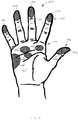
Figur 5 eine rechte Hand mit Markierungen von Reflexzonen. -
Figur 5 zeigt die Draufsicht der Innenseite einer menschlichen rechten Hand 101. Die Hand 101 weist einen Daumen 102, einen Zeigefinger 103, einen Mittelfinger 104, einen Ringfinger 105 und einen kleinen Finger 106 auf. Die Finger 103 bis 106 weisen jeweils an ihren freiliegenden Längsenden eine Fingerspitze 107 auf, wobei die Finger 103 bis 106 an der Hand 101 jeweils mit einer Fingerwurzel 108 an einer Handfläche 101 gelenkig sind. An den Fingerspitzen 107 ist jeweils eine Fingerkuppe 110 angeordnet, wohingegen der Daumen 102 eine Daumenkuppe 109 aufweist. - An den Fingerkuppen 110 sind jeweils Reflexzonen 114 für Stirn- und Kopfhöhlen angesiedelt. Auf der Handfläche 101 sind im Bereich des kleinen Fingers 106 eine Reflexzone 116 für die Leber, im Bereich des Mittelfingers 104 und des Ringfingers 105 eine Reflexzone 117 für die Lunge und eine Reflexzone für den Solarplexus 112 und im Bereich des Zeigefingers 103 eine Reflexzone für den Magen angesiedelt.
- Wie es aus
Figuren 1 bis 4 ersichtlich ist, weist ein Handgerät 1 ein Gehäuse 2 auf, das eine Eingabetaste 3 für den Daumen 102, eine Eingabetaste 4 für den Zeigefinger 103, eine Eingabetaste 4 für den Mittelfinger 104, eine Eingabetaste 6 für den Ringfinger 105 und eine Eingabetaste 7 für den kleinen Finger 106 aufweist. Ferner weist das Handgerät 1 eine Orientierungsnoppe 8 für die Wurzel des Zeigefingers 103, eine Orientierungsnoppe 9 für die Wurzel des Mittelfingers 104, eine Orientierungsnoppe 10 für die Wurzel des Ringfingers 105 und eine Orientierungsnoppe 11 für die Wurzel des kleinen Fingers 106 auf. Außerdem weist das Handgerät 1 einen Reizvorsprung 12, für die Reflexzone 112 für den Solarplexus, einen Reizvorsprung 13, für die Reflexzone 113 für den Magen, einen Reizvorsprung 14 für die Reflexzone 116 für die Leber und einen Reizvorsprung 15 für die Reflexzone 117 für die Lunge auf. - Die Eingabetasten 3 bis 7 sind als Drucktasten ausgebildet. Als vom Gehäuse 2 vorstehende und feste Vorsprünge sind die Orientierungsnoppen 8 bis 11 und die Reizvorsprünge 12 bis 15 ausgebildet. Das Gehäuse 2 ist zum Halten in der Hand 101 ergonomisch in der Art eines Handschmeichlers geformt und hat die Größe etwa eines Hühnereis.
- Beim Halten des Handgeräts 1 in der Hand 101 stehen die Orientierungsnoppen 8 bis 11 mit der Hand 101 mit ihren jeweiligen Fingerwurzeln 108 in Eingriff, so dass das Handgerät 1 von der Hand 101 mit den Fingern 102 bis 106 und der Handfläche 111 gut greifbar ist. Die Eingabetasten 3 bis 7 sind relativ zu den Orientierungsnoppen 8 bis 11 am Gehäuse derart angeordnet, dass die Eingabetasten 3 bis 7 bequem von den ihnen zugeordneten Fingern 103 bis 106 bzw. dem Daumen 102 mit ihren jeweiligen Fingerkuppen 110 bzw. der Daumenkuppe 109 gedrückt werden können. Die Reizvorsprünge 12 bis 15 sind relativ zu den Orientierungsnoppen 8 bis 11 am Gehäuse 2 derart angeordnet, dass, wenn das Handgerät 1 in der Hand 101 gehalten ist, der Reizvorsprung 12 die Reflexzone 112 für den Solarplexus, der Reizvorsprung 13 die Reflexzone 113 für den Magen, der Reizvorsprung 14 die Reflexzone 114 für die Leber und der Reizvorsprung 15 die Reflexzone 115 für die Lunge berührt.
- In
Figuren 1 und 2 ist eine erste Ausführungsform des Handgeräts 1 gezeigt, bei der die Reizvorsprünge 12 bis 15 als lokale Erhebungen am Gehäuse 2 ausgebildet sind. Die Eingabetasten 3 bis 7 sind als Drucktasten ausgebildet. - In
Figur 3 ist eine zweite Ausführungsform des Handgeräts 1 gezeigt. Die Ausgestaltung der Eingabetasten 3 bis 7 ist beispielhaft an der Eingabetaste 6 für den Ringfinger 105 gezeigt. Die Eingabetaste 6 weist einen Tastenkopf 16 auf, der zylinderartig ausgebildet ist und in einem entsprechenden Führungsschaft 17 im Gehäuse längsverschiebbar gelagert ist. Der Führungsschaft 17 ist im Gehäuse 2 derart orientiert, dass, wenn mit dem Ringfinger 105 der Tastenkopf 16 gedrückt wird, der Tastenkopf 16 im Führungsschaft 17 längsverschoben wird. Der Tastenkopf 16 ist von außerhalb des Gehäuses 2 durch den Ringfinger 105 dadurch zugänglich, dass der Tastenkopf 16 mit seinem einen Längsende aus dem Führungsschaft 17 vorsteht und dadurch vom Gehäuse 2 absteht. Am äußeren Endes des Tastenkopfs 16 ist eine Reizspitze 18 vorgesehen, die beim Drücken der Eingabetaste 6 von der Fingerkuppe 110 des Ringfingers 105 berührt wird. Dadurch wird die Reflexzone 114 für die Stirn- und Kopfhöhlen am Ringfinger 105 stimuliert. - Am der Reizspitze 17 abgewandten Längsende des Tastenkopfs 16 ist ein Übertragungsstift 19 befestigt, der mit dem Tastenkopf 16 fluchtet und bis zu einer Gehäuseöffnung 21 des Gehäuses 2 sich erstreckt, wobei der Tastenkopf 16 zusammen mit dem Übertragungsstift 19 das Gehäuse 2 vollständig durchdringt. Dadurch, dass der Tastenkopf 16 im Durchmesser größer ausgebildet ist als der Übertragungsstift 19, ist am Übergang vom Tastenkopf 16 zum Übertragungsstift 19 eine Stufe 20 ausgebildet.
- Der Übertragungsstift 19 erstreckt sich insbesondere beim Gedrücktsein der Eingabetaste 6 mit seinem Längsende 22, das dem Tastenkopf 16 abgewandt ist, durch die Gehäuseöffnung 21. Dieses Längsende 22 steht vom Gehäuse 2 ab und bildet den Reizvorsprung 16 für die Reflexzone 115 für die Lunge. Die Gehäuseöffnung 21 ist in einer Lochscheibe 23 ausgebildet, die in dem Gehäuse 2 konzentrisch um den Übertragungsstift 19 angeordnet ist. Dadurch korrespondiert die Lochscheibe 23 mit der Stufe 20, wobei an der Stufe 20 und an der Lochscheibe 23 eine erste Rückstellfeder 24 abgestützt und um den Übertragungsstift 1 angeordnet ist. Die Federkraft der Rückstellfeder 24 ist der Druckkraft beim Drücken der Eingabetaste 6 entgegengerichtet.
- Beim Drücken der Eingabetaste 6 mit dem Ringfinger 105 berührt die Fingerkuppe 110 des Ringfingers 105 die Reizspitze 18. Durch das Überwinden der Federkraft der Rückstellfeder 24 verschiebt sich der Tastenkopf 16 zusammen mit dem Übertragungsstift 19 im Führungsschaft 17, so dass der Tastenkopf 16 im Führungsschaft 17 immer mehr versenkt und das dem Tastenkopf 16 abgewandte Längsende 22 des Übertragungsstifts 19 immer mehr aus der Gehäuseöffnung 21 vorsteht. Da dieses Längsende 22 auf die Handfläche 111 und somit auf die Reflexzone 117 für die Lunge drückt, wirkt von der Handfläche 11 eine Gegenkraft auf den Übertragungsstift 19 und dem Tastenkopf 16, die entgegen der Druckkraft vom Ringfinger 105 gerichtet ist. Somit ergibt sich die Kraft, mit der das Längsende 22 des Übertragungsstifts 19 auf die Reflexzone 117 für die Lunge drückt, als die vom Ringfinger 105 auf die Reizspitze 18 ausgeübte Druckkraft reduziert um die Rückstellkraft der Rückstellfeder 24. Daraus resultiert eine Reizung der betroffenen Reflexzonen 114 und 117, die die zugeordneten Körperteile derart stimulieren soll, dass sich eine Entspannung, eine Schmerzlinderung oder eine Krankheitsheilung einstellen kann.
- In
Figur 4 ist eine dritte Ausführungsform des Handgeräts 1 gezeigt, wobei beispielhaft der Aufbau der Eingabetaste 4 für den Zeigefinger 103 gezeigt ist. Gemäß dieser Ausführungsform weist das Gehäuse 2 einen Stiftkanal 25 auf, in dem der Übertragungsstift 19 längsverschiebbar gelagert ist, der sich vollständig durch das Gehäuse 2 erstreckt. Durch die Gehäuseöffnung 21 steht bei gedrückter Eingabetaste 4 das eine Längsende 22 des Übertragungsstifts 19 vor, um als Reizvorsprung 13 für die Reflexzone 113 für den Magen zu wirken. - Der Tastenkopf 16 ist konzentrisch um den Übertragungsstift 19 angeordnet, wobei der Tastenkopf 16 einen dem Gehäuse 2 abgewandten Tastenkopfdeckel 26 aufweist. In dem Tastenkopfdeckel 26 ist eine Tastenkopföffnung 27 vorgesehen, durch die das andere Längsende des Übertragungsstifts 19, das der Gehäuseöffnung abgewandt angeordnet ist, erstreckbar ist. Dadurch, dass im Führungsschaft 17 der Tastenkopf 16 untergebracht, der im Durchmesser größer ist als der Übertragungsstift 19, und der Übertragungsstift 19 im Stiftkanal 25 angeordnet ist, ist der Übergang vom Stiftkanal 95 zum Führungsschaft 17 stufenförmig ausgebildet, wodurch ein Grund 29 vorhanden ist. Eine zweite Rückstellfeder 30 ist am Grund 29 und an der Innenseite des Tastenkopfdeckels 26 abgestützt, so dass von der Rückstellfeder 30 eine Rückstellkraft in eine Nichtgedrücktstellung der Eingabetaste 4 auf den Tastenkopf 16 ausgeübt ist.
- Der Tastenkopf 16 und der Übertragungsstift 19 sind zueinander frei verschiebbar. Beim Drücken der Eingabetaste 4 mit der Fingerkuppe 110 des Zeigefingers 103 wird der Tastenkopf 16 in den Führungsschaft 17 hinein verschoben, wobei der Übertragungsstift 19 mit seinem Längsende 28 durch die Tastenkopföffnung 27 sich erstreckt und vom Tastenkopfdeckel 26 vorsteht. Somit wird die Reflexzone 114 an der Fingerkuppe 110 des Zeigefingers 103 gereizt. Dadurch, dass mit der Fingerkuppe 110 des Zeigefingers 103 auf das Längsende 28 des Übertragungsstifts 19 gedrückt wird, verschiebt sich der Übertragungsstift 19 im Stiftkanal 25, so dass das andere Längsende 22 des Übertragungsstifts 19 aus der Gehäuseöffnung 21 immer mehr ausgefahren und die Reflexzone 113 für den Magen gereizt wird. In Abhängigkeit der Kennlinie der Rückstellfeder 30, der Überstände des Übertragungsstifts 19 an seinen Längsenden 22 und 28 sowie der Reibung zwischen dem Übertragungsstift 19 und dem Stiftkanal 25 und/oder dem Tastenkopf 16 und dem Führungsschaft 17 ist der Grad der Reizung der Reflexzone 114 an der Fingerkuppe und der Reflexzone 113 auf der Handfläche 111 einstellbar.
- Die beschriebenen Ausführungsformen der Eingabetasten 3 bis 7 und andere Ausführungen sind im Handgerät 1 als beliebig kombinierbar denkbar.
- In jeder der Ausführungen des Handgeräts 1 sind die Eingabetasten 3 bis 7 via Signalleitungen 31 mit einer Datenverarbeitungseinheit 32 verschaltet. Mit Hilfe der Datenverarbeitungseinheit 32 werden die mit den Eingabetasten 3 bis 7 eingegebenen Daten verarbeitet. Hierzu weist die Datenverarbeitungseinheit 32 eine Eingabeeinheit 33, mit der die Dateneingabe gesteuert wird, und einen Speicher 34 auf, mit dem die eingegebenen Daten gespeichert werden. Zum Betrieb der Datenverarbeitungseinheit 32 weist diese eine Batterie 35 zur Stromversorgung auf. Ferner weist die Datenverarbeitungseinheit 32 eine Ausgabeeinheit 36 auf, mit der via einen Ausgabeanschluss 37 die im Speicher 34 gespeicherten Daten zu externen Geräte ausgelesen werden können.
- Die Eingabetaste 3 ist als eine Multifunktionstaste ausgebildet, mit der sieben Stellungen mit dem Daumen 102 schaltbar sind. Die Eingabeeinheit 32 ist derart eingerichtet, dass in Abhängigkeit der jeweiligen Stellung der Eingabetaste 3 den Eingabetasten 4 bis 7 Gruppen von Buchstaben des Alphabets zugeordnet werden. In derartiger Konfiguration dient das Handgerät 1 als Texteingabegerät, wobei mit den Fingern 103 bis 106 den Eingabetasten 4 bis 7 entsprechend der Betätigung der Eingabetaste mit dem Daumen 102 Texte eingegeben werden können, die in der Speichereinheit 34 gespeichert und mit der Ausgabeeinheit 36 via den Ausgabeanschluss 37 wieder ausgelesen werden können. Zum Ausgeben der Daten kann die Ausgabeeinheit 36 ferner ein Wlan-Modul aufweisen, mit dem via Internet die Daten ausgelesen werden können.
- Denkbar ist es auch, dass das Handgerät 1 mit seiner Anordnung an den Eingabetasten 3 bis 7 derart symmetrisch aufgebaut ist, dass das Handgerät 1 beidhändig unter der Stimulation der relevanten Reflexzonen 112 bis 117 bedienbar ist, wodurch das Handgerät 1 beidhändig anwendbar ist, also gleichwertig sowohl von der rechten Hand als auch von der linken Hand gehalten und bedient werden kann und dabei das Handgerät 1 sowohl für einen Rechtshänder als auch für einen Linkshänder geeignet ist.
-
- 1
- Handgerät
- 2
- Gehäuse
- 3
- Eingabetaste für den Daumen
- 4
- Eingabetaste für den Zeigefinger
- 5
- Eingabetaste für den Mittelfinger
- 6
- Eingabetaste für den Ringfinger
- 7
- Eingabetaste für den kleinen Finger
- 8
- Orientierungsnoppe für die Wurzel des Zeigefingers
- 9
- Orientierungsnoppe für die Wurzel des Mittelfingers
- 10
- Orientierungsnoppe für die Wurzel des Rinngfingers
- 11
- Orientierungsnoppe für die Wurzel des kleinen Fingers
- 12
- Reizvorsprung für Reflexzone für Solarplexus
- 13
- Reizvorsprung für Reflexzone für Magen
- 14
- Reizvorsprung für Reflexzone für Leber
- 15
- Reizvorsprung für Reflexzone für Lunge
- 16
- Tastenkopf
- 17
- Führungsschaft
- 18
- Reizspitze
- 19
- Übertragungsstift
- 20
- Stufe
- 21
- Gehäuseöffnung
- 22
- erstes Längsende des Übertragungsstifts
- 23
- Lochscheibe
- 24
- erste Rückstellfeder
- 25
- Stiftkanal
- 26
- Tastenkopfdeckel
- 27
- Tastenkopföffnung
- 28
- zweites Längsende des Übertragungsstifts
- 29
- Grund
- 30
- zweite Rückstellfeder
- 31
- Signalleitung
- 32
- Datenverarbeitungseinheit
- 33
- Eingabeeinheit
- 34
- Speicher
- 35
- Batterie
- 36
- Ausgabeeinheit
- 37
- Ausgabeanschluss
- 101
- Hand
- 102
- Daumen
- 103
- Zeigefinger
- 104
- Mittelfinger
- 105
- Ringfinger
- 106
- Kleiner Finger
- 107
- Fingerspitze
- 108
- Fingerwurzel
- 109
- Daumenkuppe
- 110
- Fingerkuppe
- 111
- Handfläche
- 112
- Reflexzone für Solarplexus
- 113
- Reflexzone für Magen
- 114
- Reflexzonen für Stirn- und Kopfhöhlen
- 115
- Reflexzone für Gehirn
- 116
- Reflexzone für Leber
- 117
- Reflexzone für Lunge
Claims (14)
- Handgerät zur Dateneingabe, mit einer Datenverarbeitungseinheit (32) und einem Gehäuse (2), das ergonomisch zum in einer Hand (101) Halten in der Art eines Handschmeichlers an die Hand (101) angepasst geformt ist, sowie mindestens einer Eingabetaste (3 bis 7), die mit der Datenverarbeitungseinheit (32) zur Verarbeitung der Dateneingabe durch die Eingabetaste (3 bis 7) gekoppelt ist und derart an dem Gehäuse (2) angeordnet ist, dass, wenn das Handgerät (1) in der Hand (101) gehalten ist, von mindestens einem der vier Finger (103 bis 106) oder dem Daumen (102) der Hand (101) die Eingabetaste (4 bis 7) zur Dateneingabe drückbar und dadurch eine Druckkraft von dem Finger (103 bis 106) oder dem Daumen (3) via das Handgerät (1) auf die Handfläche (111) übertragbar ist, dadurch gekennzeichnet, dass eine Oberflächenstelle des Gehäuses (2), die der Eingabetaste (4 bis 7) abgewandt angeordnet ist und zu der, wenn das Handgerät (1) in der Hand (101) gehalten ist, unmittelbar benachbart mindestens eine der Reflexzonen (112 bis 117) der Handfläche (111) angeordnet ist, mit mindestens einem von der Oberflächenstelle vorstehenden Reizvorsprung (12 bis 15) versehen ist, so dass vom Drücken der Eingabetaste (4 bis 7) via den Reizvorsprung (12 bis 15) Nervenendpunkte der Reflexzone (112 bis 117) reizbar sind, wodurch der der Reflexzone (112 bis 117) zugeordnete Körperteil während der Dateneingabe stimuliert ist, dadurch gekennzeichnet, dass das Gehäuse (2) in der Oberflächenstelle eine Gehäuseöffnung (21) und das Handgerät (1) einen verschiebbar gelagerten Übertragungsstift (19) aufweist, der mit der Eingabetaste (3 bis 7) gekuppelt ist, dass, wenn die Eingabetaste (3 bis 7) gedrückt ist, der Übertragungsstift (19) mit seinem einen Längsende (22) durch die Gehäuseöffnung (21) sich erstreckt und von der Oberflächenstelle vorsteht, wodurch das Längsende (22) den Reizvorsprung (12 bis 15) bildet.
- Handgerät gemäß Anspruch 1, wobei das Gehäuse (2) mindestens eine einer der Wurzeln (108), an denen die Finger (103 bis 106) an der Handfläche (111) gelenkig sind, der Finger (103 bis 106) zugeordnete Orientierungsnoppe (9 bis 11) aufweist, die derart angeordnet ist, dass, wenn das Handgerät (1) in der in der Hand (101) gehalten ist, die Orientierungsnoppe (9 bis 11) mit ihrer zugeordneten Wurzel (108) in Eingriff steht und der Reizvorsprung (12 bis 15) mit der ihm zugeordneten Reflexzone (112 bis 117) in Berührkontakt bringbar und die Eingabetaste (3 bis 7) von dem ihr zugeordneten Finger (103 bis 106) / Daumen (102) drückbar ist.
- Handgerät gemäß Anspruch 1 oder 2, wobei mit der Fingerkuppe (110) / Daumenkuppe (109) des der Eingabetaste zugeordneten Fingers (103 bis 106) / Daumens (102)die Eingabetaste drückbar ist.
- Handgerät gemäß einem der Ansprüche 1 bis 3, wobei der Übertragungsstift (19) derart dimensioniert, gelagert und mit der Eingabetaste (3 bis 7) gekuppelt ist, dass, wenn die Eingabetaste (3 bis 7) nicht gedrückt ist, das Längsende (22) des Übertragungsstifts (19) in der Gehäuseöffnung (21) versenkt ist.
- Handgerät gemäß einem der Ansprüche 1 bis 4, wobei die Eingabetaste (3 bis 7) einen verschiebbaren Tastenkopf (16) zum Drücken der Eingabetaste (3 bis 7) aufweist, der in Verlängerung zum Übertragungsstift (19) an diesem befestigt ist, so dass der Tastenkopf (16) zusammen mit dem Übertragungsstift (19) das Gehäuse (2) vollständig durchdringt.
- Handgerät gemäß Anspruch 5, wobei der Tastenkopf (16) eine Reitzspitze (18) aufwest, die vom Gehäuse (2) absteht, wodurch der Finger (103 bis 106) / Daumen (103) beim Drücken der Eingabetaste (3 bis 7) gereizt ist.
- Handgerät gemäß einem der Ansprüche 1 bis 4, wobei die Eingabetaste (3 bis 7) einen verschiebbaren Tastenkopf (16) zum Drücken der Eingabetaste (3 bis 7) aufweist und der Übertragungsstift (19) das Gehäuse (2) vollständig durchdringt sowie im Tastenkopf (16) sich erstreckt, so dass, wenn die Eingabetaste (3 bis 7) gedrückt ist, das Längsende (28) des Übertragungsstifts (19), das der Gehäuseöffnung (21) abgewandt angeordnet ist, durch eine Tastenkopföffnung (27) des Tastenkopfs (16) sich erstreckt und von dem Tastenkopf (16) vorsteht, wodurch der Finger (103 bis 106) / Daumen (102) beim Drücken der Eingabetaste (3 bis 7) gereizt ist.
- Handgerät gemäß einem der Ansprüche 5 bis 7, wobei das Handgerät (1) ein Vorspannmittel (24, 30) aufweist, das am Tastenkopf (16) angreift und mit seiner der Druckkraft entgegenwirkenden Vorspannkraft den Tastenkopf (16) in dessen Nichtgedrücktstellung treibt, wobei das Vorspannmittel (24, 30) derart dimensioniert ist, dass die Vorspannkraft zu derjenigen Größe der Druckkraft führt, dass der der Reflexzone (112 bis 117) zugeordnete Körperteil während der Dateneingabe zur Entspannung, Schmerzlinderung oder Krankheitsheilung stimuliert ist.
- Handgerät gemäß einem der Ansprüche 1 bis 8, wobei der Übertragungsstift (19) gebogen geformt ist.
- Handgerät gemäß einem der Ansprüche 1 bis 9, wobei das Handgerät (1) für jeden der vier Finger (103 bis 106) jeweils eine der Eingabetasten (4 bis 7) und für den Daumen (102) eine zusätzliche Eingabetaste (3) aufweist, die als eine Multifunktionstaste ausgebildet ist, mit der verschiedene Funktionalitäten der Eingabetasten (4 bis 7) für die Finger (103 bis 106) schaltbar sind.
- Handgerät gemäß einem der Ansprüche 1 bis 10, wobei die Datenverarbeitungseinheit (32) einen Speicher (34) aufweist, mit dem die mit den Eingabetasten (3 bis 7) eingegeben Daten speicherbar sind.
- Fernbedienungsgerät zum Fernbedienen eines Apparats, mit einem Handgerät (1) gemäß einem der Ansprüche 1 bis 11.
- Mobiltelefon mit einem Handgerät (1) gemäß einem der Ansprüche 1 bis 11.
- Spielgerät mit einem Handgerät (1) gemäß einem der Ansprüche 1 bis 11.
Priority Applications (2)
| Application Number | Priority Date | Filing Date | Title |
|---|---|---|---|
| EP14166403.7A EP2940974B1 (de) | 2014-04-29 | 2014-04-29 | Handgerät zur dateneingabe sowie fernbedienungsgerät, mobiltelefon und spielgerät |
| PCT/EP2015/059215 WO2015165907A1 (en) | 2014-04-29 | 2015-04-28 | Handheld device for data input as well as remote control device, mobile telephone and gaming device |
Applications Claiming Priority (1)
| Application Number | Priority Date | Filing Date | Title |
|---|---|---|---|
| EP14166403.7A EP2940974B1 (de) | 2014-04-29 | 2014-04-29 | Handgerät zur dateneingabe sowie fernbedienungsgerät, mobiltelefon und spielgerät |
Publications (2)
| Publication Number | Publication Date |
|---|---|
| EP2940974A1 EP2940974A1 (de) | 2015-11-04 |
| EP2940974B1 true EP2940974B1 (de) | 2017-01-11 |
Family
ID=50679862
Family Applications (1)
| Application Number | Title | Priority Date | Filing Date |
|---|---|---|---|
| EP14166403.7A Not-in-force EP2940974B1 (de) | 2014-04-29 | 2014-04-29 | Handgerät zur dateneingabe sowie fernbedienungsgerät, mobiltelefon und spielgerät |
Country Status (2)
| Country | Link |
|---|---|
| EP (1) | EP2940974B1 (de) |
| WO (1) | WO2015165907A1 (de) |
Family Cites Families (3)
| Publication number | Priority date | Publication date | Assignee | Title |
|---|---|---|---|---|
| US4905001A (en) * | 1987-10-08 | 1990-02-27 | Penner Henry C | Hand-held finger movement actuated communication devices and systems employing such devices |
| US6762749B1 (en) * | 1997-01-09 | 2004-07-13 | Virtouch Ltd. | Tactile interface system for electronic data display system |
| DE102004042884B4 (de) * | 2004-09-04 | 2009-09-24 | Hönicke, Bernd | Kommunikationsgerät für sinnesbehinderte Personen |
-
2014
- 2014-04-29 EP EP14166403.7A patent/EP2940974B1/de not_active Not-in-force
-
2015
- 2015-04-28 WO PCT/EP2015/059215 patent/WO2015165907A1/en not_active Ceased
Non-Patent Citations (1)
| Title |
|---|
| None * |
Also Published As
| Publication number | Publication date |
|---|---|
| EP2940974A1 (de) | 2015-11-04 |
| WO2015165907A1 (en) | 2015-11-05 |
Similar Documents
| Publication | Publication Date | Title |
|---|---|---|
| DE60001107T2 (de) | Sichere und handliche hinweisanordung | |
| EP0920673B1 (de) | Verfahren und vorrichtung zur einhändigen eingabe von daten | |
| DE102010052759A1 (de) | Geräteanordnung zur Simulation der gegenseitigen Berührung zweier Menschen aus der Ferne | |
| DE69328671T2 (de) | Handcodierinstrument | |
| EP3787566A1 (de) | Fingerorthese und verfahren zu ihrer herstellung | |
| DE102009023579B4 (de) | Tastfeld-Vorrichtung | |
| DE4035273A1 (de) | Eingabeeinrichtung fuer rechner, elektronische schreibmaschine u. ae. | |
| DE60210092T2 (de) | Tastatur | |
| EP0809223B1 (de) | Vorrichtung zum Übermitteln von Zeichen und Buchstaben von einer Datenverarbeitungsanlage an eine taubblinde Person | |
| EP2940974A1 (de) | Handgerät zur Dateneingabe sowie Fernbedienungsgerät, Mobiltelefon und Spielgerät | |
| DE3889352T2 (de) | Dateneingabesystem für einen Rechner. | |
| WO2006024554A2 (de) | Mechanische eingabeeinheit für eine anzeigeeinheit mit einer druckempfindlichen oberfläche | |
| DE102022134798B4 (de) | Passives Akupressurgerät | |
| DE102017102280A1 (de) | Massagegerät mit einem Massageelement | |
| KR200188851Y1 (ko) | 컴퓨터 조작용 마우스 | |
| DE102008018194A1 (de) | Pad zur permanent beidhändigen Entlastung von Handgelenk und Unterarm | |
| DE29513538U1 (de) | Fernbedienung für ein Elektrogerät | |
| DE10127589C2 (de) | Bedienelement für Computer | |
| DE102011052331B4 (de) | Schreibgerät mit mechanischer Korrektur der Klemmkräfte | |
| DE102013105663A1 (de) | Touch-Eingabegerät | |
| DE102008058196A1 (de) | Mehrfunktions- oder Flachmaus für neue, handschonende und leistungssteigernde Computermaus für PC's, Laptops und elektronische Steuergeräte | |
| WO2017162712A1 (de) | Eingabegeraet in form einer einhandtastatur | |
| DE3521508A1 (de) | Lochtaste | |
| CN2655333Y (zh) | 新型普通键盘 | |
| DE102004035143A1 (de) | Vorrichtung zur Umwandlung einer Handbewegung in eine elektrische Signalfolge |
Legal Events
| Date | Code | Title | Description |
|---|---|---|---|
| PUAI | Public reference made under article 153(3) epc to a published international application that has entered the european phase |
Free format text: ORIGINAL CODE: 0009012 |
|
| 17P | Request for examination filed |
Effective date: 20150223 |
|
| AK | Designated contracting states |
Kind code of ref document: A1 Designated state(s): AL AT BE BG CH CY CZ DE DK EE ES FI FR GB GR HR HU IE IS IT LI LT LU LV MC MK MT NL NO PL PT RO RS SE SI SK SM TR |
|
| AX | Request for extension of the european patent |
Extension state: BA ME |
|
| GRAP | Despatch of communication of intention to grant a patent |
Free format text: ORIGINAL CODE: EPIDOSNIGR1 |
|
| INTG | Intention to grant announced |
Effective date: 20160727 |
|
| GRAS | Grant fee paid |
Free format text: ORIGINAL CODE: EPIDOSNIGR3 |
|
| GRAA | (expected) grant |
Free format text: ORIGINAL CODE: 0009210 |
|
| AK | Designated contracting states |
Kind code of ref document: B1 Designated state(s): AL AT BE BG CH CY CZ DE DK EE ES FI FR GB GR HR HU IE IS IT LI LT LU LV MC MK MT NL NO PL PT RO RS SE SI SK SM TR |
|
| REG | Reference to a national code |
Ref country code: GB Ref legal event code: FG4D Free format text: NOT ENGLISH |
|
| REG | Reference to a national code |
Ref country code: CH Ref legal event code: EP |
|
| REG | Reference to a national code |
Ref country code: AT Ref legal event code: REF Ref document number: 862206 Country of ref document: AT Kind code of ref document: T Effective date: 20170115 |
|
| REG | Reference to a national code |
Ref country code: IE Ref legal event code: FG4D Free format text: LANGUAGE OF EP DOCUMENT: GERMAN |
|
| REG | Reference to a national code |
Ref country code: DE Ref legal event code: R096 Ref document number: 502014002447 Country of ref document: DE |
|
| REG | Reference to a national code |
Ref country code: FR Ref legal event code: PLFP Year of fee payment: 4 |
|
| REG | Reference to a national code |
Ref country code: LT Ref legal event code: MG4D |
|
| REG | Reference to a national code |
Ref country code: NL Ref legal event code: MP Effective date: 20170111 |
|
| PG25 | Lapsed in a contracting state [announced via postgrant information from national office to epo] |
Ref country code: NL Free format text: LAPSE BECAUSE OF FAILURE TO SUBMIT A TRANSLATION OF THE DESCRIPTION OR TO PAY THE FEE WITHIN THE PRESCRIBED TIME-LIMIT Effective date: 20170111 |
|
| PG25 | Lapsed in a contracting state [announced via postgrant information from national office to epo] |
Ref country code: IS Free format text: LAPSE BECAUSE OF FAILURE TO SUBMIT A TRANSLATION OF THE DESCRIPTION OR TO PAY THE FEE WITHIN THE PRESCRIBED TIME-LIMIT Effective date: 20170511 Ref country code: HR Free format text: LAPSE BECAUSE OF FAILURE TO SUBMIT A TRANSLATION OF THE DESCRIPTION OR TO PAY THE FEE WITHIN THE PRESCRIBED TIME-LIMIT Effective date: 20170111 Ref country code: LT Free format text: LAPSE BECAUSE OF FAILURE TO SUBMIT A TRANSLATION OF THE DESCRIPTION OR TO PAY THE FEE WITHIN THE PRESCRIBED TIME-LIMIT Effective date: 20170111 Ref country code: GR Free format text: LAPSE BECAUSE OF FAILURE TO SUBMIT A TRANSLATION OF THE DESCRIPTION OR TO PAY THE FEE WITHIN THE PRESCRIBED TIME-LIMIT Effective date: 20170412 Ref country code: NO Free format text: LAPSE BECAUSE OF FAILURE TO SUBMIT A TRANSLATION OF THE DESCRIPTION OR TO PAY THE FEE WITHIN THE PRESCRIBED TIME-LIMIT Effective date: 20170411 Ref country code: FI Free format text: LAPSE BECAUSE OF FAILURE TO SUBMIT A TRANSLATION OF THE DESCRIPTION OR TO PAY THE FEE WITHIN THE PRESCRIBED TIME-LIMIT Effective date: 20170111 |
|
| PG25 | Lapsed in a contracting state [announced via postgrant information from national office to epo] |
Ref country code: LV Free format text: LAPSE BECAUSE OF FAILURE TO SUBMIT A TRANSLATION OF THE DESCRIPTION OR TO PAY THE FEE WITHIN THE PRESCRIBED TIME-LIMIT Effective date: 20170111 Ref country code: BG Free format text: LAPSE BECAUSE OF FAILURE TO SUBMIT A TRANSLATION OF THE DESCRIPTION OR TO PAY THE FEE WITHIN THE PRESCRIBED TIME-LIMIT Effective date: 20170411 Ref country code: RS Free format text: LAPSE BECAUSE OF FAILURE TO SUBMIT A TRANSLATION OF THE DESCRIPTION OR TO PAY THE FEE WITHIN THE PRESCRIBED TIME-LIMIT Effective date: 20170111 Ref country code: PT Free format text: LAPSE BECAUSE OF FAILURE TO SUBMIT A TRANSLATION OF THE DESCRIPTION OR TO PAY THE FEE WITHIN THE PRESCRIBED TIME-LIMIT Effective date: 20170511 Ref country code: SE Free format text: LAPSE BECAUSE OF FAILURE TO SUBMIT A TRANSLATION OF THE DESCRIPTION OR TO PAY THE FEE WITHIN THE PRESCRIBED TIME-LIMIT Effective date: 20170111 Ref country code: ES Free format text: LAPSE BECAUSE OF FAILURE TO SUBMIT A TRANSLATION OF THE DESCRIPTION OR TO PAY THE FEE WITHIN THE PRESCRIBED TIME-LIMIT Effective date: 20170111 Ref country code: PL Free format text: LAPSE BECAUSE OF FAILURE TO SUBMIT A TRANSLATION OF THE DESCRIPTION OR TO PAY THE FEE WITHIN THE PRESCRIBED TIME-LIMIT Effective date: 20170111 |
|
| REG | Reference to a national code |
Ref country code: DE Ref legal event code: R097 Ref document number: 502014002447 Country of ref document: DE |
|
| PG25 | Lapsed in a contracting state [announced via postgrant information from national office to epo] |
Ref country code: IT Free format text: LAPSE BECAUSE OF FAILURE TO SUBMIT A TRANSLATION OF THE DESCRIPTION OR TO PAY THE FEE WITHIN THE PRESCRIBED TIME-LIMIT Effective date: 20170111 Ref country code: EE Free format text: LAPSE BECAUSE OF FAILURE TO SUBMIT A TRANSLATION OF THE DESCRIPTION OR TO PAY THE FEE WITHIN THE PRESCRIBED TIME-LIMIT Effective date: 20170111 Ref country code: SK Free format text: LAPSE BECAUSE OF FAILURE TO SUBMIT A TRANSLATION OF THE DESCRIPTION OR TO PAY THE FEE WITHIN THE PRESCRIBED TIME-LIMIT Effective date: 20170111 Ref country code: RO Free format text: LAPSE BECAUSE OF FAILURE TO SUBMIT A TRANSLATION OF THE DESCRIPTION OR TO PAY THE FEE WITHIN THE PRESCRIBED TIME-LIMIT Effective date: 20170111 Ref country code: CZ Free format text: LAPSE BECAUSE OF FAILURE TO SUBMIT A TRANSLATION OF THE DESCRIPTION OR TO PAY THE FEE WITHIN THE PRESCRIBED TIME-LIMIT Effective date: 20170111 |
|
| PLBE | No opposition filed within time limit |
Free format text: ORIGINAL CODE: 0009261 |
|
| STAA | Information on the status of an ep patent application or granted ep patent |
Free format text: STATUS: NO OPPOSITION FILED WITHIN TIME LIMIT |
|
| PG25 | Lapsed in a contracting state [announced via postgrant information from national office to epo] |
Ref country code: DK Free format text: LAPSE BECAUSE OF FAILURE TO SUBMIT A TRANSLATION OF THE DESCRIPTION OR TO PAY THE FEE WITHIN THE PRESCRIBED TIME-LIMIT Effective date: 20170111 Ref country code: SM Free format text: LAPSE BECAUSE OF FAILURE TO SUBMIT A TRANSLATION OF THE DESCRIPTION OR TO PAY THE FEE WITHIN THE PRESCRIBED TIME-LIMIT Effective date: 20170111 |
|
| REG | Reference to a national code |
Ref country code: CH Ref legal event code: PL |
|
| 26N | No opposition filed |
Effective date: 20171012 |
|
| REG | Reference to a national code |
Ref country code: IE Ref legal event code: MM4A |
|
| PG25 | Lapsed in a contracting state [announced via postgrant information from national office to epo] |
Ref country code: MC Free format text: LAPSE BECAUSE OF FAILURE TO SUBMIT A TRANSLATION OF THE DESCRIPTION OR TO PAY THE FEE WITHIN THE PRESCRIBED TIME-LIMIT Effective date: 20170111 |
|
| PG25 | Lapsed in a contracting state [announced via postgrant information from national office to epo] |
Ref country code: LI Free format text: LAPSE BECAUSE OF NON-PAYMENT OF DUE FEES Effective date: 20170430 Ref country code: CH Free format text: LAPSE BECAUSE OF NON-PAYMENT OF DUE FEES Effective date: 20170430 Ref country code: LU Free format text: LAPSE BECAUSE OF NON-PAYMENT OF DUE FEES Effective date: 20170429 Ref country code: SI Free format text: LAPSE BECAUSE OF FAILURE TO SUBMIT A TRANSLATION OF THE DESCRIPTION OR TO PAY THE FEE WITHIN THE PRESCRIBED TIME-LIMIT Effective date: 20170111 |
|
| REG | Reference to a national code |
Ref country code: BE Ref legal event code: MM Effective date: 20170430 |
|
| REG | Reference to a national code |
Ref country code: FR Ref legal event code: PLFP Year of fee payment: 5 |
|
| PG25 | Lapsed in a contracting state [announced via postgrant information from national office to epo] |
Ref country code: IE Free format text: LAPSE BECAUSE OF NON-PAYMENT OF DUE FEES Effective date: 20170429 |
|
| PG25 | Lapsed in a contracting state [announced via postgrant information from national office to epo] |
Ref country code: BE Free format text: LAPSE BECAUSE OF NON-PAYMENT OF DUE FEES Effective date: 20170430 |
|
| PG25 | Lapsed in a contracting state [announced via postgrant information from national office to epo] |
Ref country code: MT Free format text: LAPSE BECAUSE OF FAILURE TO SUBMIT A TRANSLATION OF THE DESCRIPTION OR TO PAY THE FEE WITHIN THE PRESCRIBED TIME-LIMIT Effective date: 20170111 |
|
| PG25 | Lapsed in a contracting state [announced via postgrant information from national office to epo] |
Ref country code: HU Free format text: LAPSE BECAUSE OF FAILURE TO SUBMIT A TRANSLATION OF THE DESCRIPTION OR TO PAY THE FEE WITHIN THE PRESCRIBED TIME-LIMIT; INVALID AB INITIO Effective date: 20140429 |
|
| PGFP | Annual fee paid to national office [announced via postgrant information from national office to epo] |
Ref country code: DE Payment date: 20190430 Year of fee payment: 6 |
|
| PGFP | Annual fee paid to national office [announced via postgrant information from national office to epo] |
Ref country code: FR Payment date: 20190521 Year of fee payment: 6 |
|
| PG25 | Lapsed in a contracting state [announced via postgrant information from national office to epo] |
Ref country code: CY Free format text: LAPSE BECAUSE OF FAILURE TO SUBMIT A TRANSLATION OF THE DESCRIPTION OR TO PAY THE FEE WITHIN THE PRESCRIBED TIME-LIMIT Effective date: 20170111 |
|
| PGFP | Annual fee paid to national office [announced via postgrant information from national office to epo] |
Ref country code: GB Payment date: 20190523 Year of fee payment: 6 |
|
| PG25 | Lapsed in a contracting state [announced via postgrant information from national office to epo] |
Ref country code: MK Free format text: LAPSE BECAUSE OF FAILURE TO SUBMIT A TRANSLATION OF THE DESCRIPTION OR TO PAY THE FEE WITHIN THE PRESCRIBED TIME-LIMIT Effective date: 20170111 |
|
| PG25 | Lapsed in a contracting state [announced via postgrant information from national office to epo] |
Ref country code: TR Free format text: LAPSE BECAUSE OF FAILURE TO SUBMIT A TRANSLATION OF THE DESCRIPTION OR TO PAY THE FEE WITHIN THE PRESCRIBED TIME-LIMIT Effective date: 20170111 |
|
| PG25 | Lapsed in a contracting state [announced via postgrant information from national office to epo] |
Ref country code: AL Free format text: LAPSE BECAUSE OF FAILURE TO SUBMIT A TRANSLATION OF THE DESCRIPTION OR TO PAY THE FEE WITHIN THE PRESCRIBED TIME-LIMIT Effective date: 20170111 |
|
| REG | Reference to a national code |
Ref country code: AT Ref legal event code: MM01 Ref document number: 862206 Country of ref document: AT Kind code of ref document: T Effective date: 20190429 |
|
| REG | Reference to a national code |
Ref country code: DE Ref legal event code: R119 Ref document number: 502014002447 Country of ref document: DE |
|
| PG25 | Lapsed in a contracting state [announced via postgrant information from national office to epo] |
Ref country code: AT Free format text: LAPSE BECAUSE OF NON-PAYMENT OF DUE FEES Effective date: 20190429 |
|
| PG25 | Lapsed in a contracting state [announced via postgrant information from national office to epo] |
Ref country code: FR Free format text: LAPSE BECAUSE OF NON-PAYMENT OF DUE FEES Effective date: 20200430 Ref country code: DE Free format text: LAPSE BECAUSE OF NON-PAYMENT OF DUE FEES Effective date: 20201103 |
|
| GBPC | Gb: european patent ceased through non-payment of renewal fee |
Effective date: 20200429 |
|
| PG25 | Lapsed in a contracting state [announced via postgrant information from national office to epo] |
Ref country code: GB Free format text: LAPSE BECAUSE OF NON-PAYMENT OF DUE FEES Effective date: 20200429 |