EP2940974B1 - Dispositif portable pour une saisie de données ainsi que la télécommande, téléphone mobile et console de jeu. - Google Patents
Dispositif portable pour une saisie de données ainsi que la télécommande, téléphone mobile et console de jeu. Download PDFInfo
- Publication number
- EP2940974B1 EP2940974B1 EP14166403.7A EP14166403A EP2940974B1 EP 2940974 B1 EP2940974 B1 EP 2940974B1 EP 14166403 A EP14166403 A EP 14166403A EP 2940974 B1 EP2940974 B1 EP 2940974B1
- Authority
- EP
- European Patent Office
- Prior art keywords
- key
- handheld device
- input
- input key
- casing
- Prior art date
- Legal status (The legal status is an assumption and is not a legal conclusion. Google has not performed a legal analysis and makes no representation as to the accuracy of the status listed.)
- Not-in-force
Links
Images

Classifications
-
- H—ELECTRICITY
- H04—ELECTRIC COMMUNICATION TECHNIQUE
- H04M—TELEPHONIC COMMUNICATION
- H04M1/00—Substation equipment, e.g. for use by subscribers
- H04M1/02—Constructional features of telephone sets
- H04M1/23—Construction or mounting of dials or of equivalent devices; Means for facilitating the use thereof
- H04M1/236—Construction or mounting of dials or of equivalent devices; Means for facilitating the use thereof including keys on side or rear faces
-
- G—PHYSICS
- G06—COMPUTING OR CALCULATING; COUNTING
- G06F—ELECTRIC DIGITAL DATA PROCESSING
- G06F3/00—Input arrangements for transferring data to be processed into a form capable of being handled by the computer; Output arrangements for transferring data from processing unit to output unit, e.g. interface arrangements
- G06F3/01—Input arrangements or combined input and output arrangements for interaction between user and computer
- G06F3/02—Input arrangements using manually operated switches, e.g. using keyboards or dials
- G06F3/0202—Constructional details or processes of manufacture of the input device
- G06F3/0219—Special purpose keyboards
-
- G—PHYSICS
- G06—COMPUTING OR CALCULATING; COUNTING
- G06F—ELECTRIC DIGITAL DATA PROCESSING
- G06F3/00—Input arrangements for transferring data to be processed into a form capable of being handled by the computer; Output arrangements for transferring data from processing unit to output unit, e.g. interface arrangements
- G06F3/01—Input arrangements or combined input and output arrangements for interaction between user and computer
- G06F3/02—Input arrangements using manually operated switches, e.g. using keyboards or dials
- G06F3/023—Arrangements for converting discrete items of information into a coded form, e.g. arrangements for interpreting keyboard generated codes as alphanumeric codes, operand codes or instruction codes
- G06F3/0231—Cordless keyboards
-
- H—ELECTRICITY
- H01—ELECTRIC ELEMENTS
- H01H—ELECTRIC SWITCHES; RELAYS; SELECTORS; EMERGENCY PROTECTIVE DEVICES
- H01H9/00—Details of switching devices, not covered by groups H01H1/00 - H01H7/00
- H01H9/02—Bases, casings, or covers
- H01H9/0214—Hand-held casings
Definitions
- the invention relates to a handheld device for data input and a remote control device, a mobile phone and a game device, which have the handset.
- a mobile phone has, for example, a keyboard or a touchscreen with which telephone numbers, messages or data entries can be entered into the mobile phone.
- a remote control device for example, a TV or a stereo system has various program and function keys that are built as push buttons or membrane keys in the remote control device.
- the problem is that small size handset while handy in housing, but difficult to use and manual handling.
- the frequent and quick operation of the handset can cause tension in the hand, arm and neck of the operator. These tensions can affect mobility and cause pain, which may cause discomfort and even disability for the operator.
- the operator's psyche may also be impaired, which may influence the decisions of the operator when operating the hand-held device.
- the object of the invention is to provide a hand-held device for data input and a remote control device, a mobile phone and a game device that have the handset, with the devices allows a fast and convenient data entry is where the handset operator is relaxed and comfortable.
- the data input handset of the present invention comprises a data processing unit and a housing ergonomically shaped to be hand-shaped in a hand-held manner, and at least one input key coupled to the data processing unit for processing data input by the enter key and disposed on the housing such that, when the handset is held in the hand, of at least one of the four fingers or the thumb of the hand presses the enter key for data entry and thereby a pressing force from the finger or the thumb via the handset to the Hand surface is transferable, wherein a surface location of the housing, which is arranged away from the input key and to which, when the handset is held in the hand, immediately adjacent at least one of the reflection zones of the palm is arranged, with at least one of the surface site projecting stimulus projection ve is so that by pressing the enter button via the stimulus projection nerve end points of the reflex zone are irritated, is stimulated by the reflex zone associated body part during data entry.
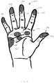
- reflex zones On the palm are reflex zones, which are assigned for example to the solar plexus, the stomach, the liver or the lung.
- reflex zones On the fingertips are reflex zones, which are assigned to the front and head cavities, and at the thumb tip is a reflex zone, which is assigned to the brain. If the nerve end points of the reflex zones are stimulated during data entry, a beneficial and relaxing effect is established on the corresponding associated body parts, namely the solar plexus, the stomach, the frontal and the head cavities, the brain, the liver and the lungs.
- the well-being of the person performing the data entry with the handset of the invention is increased.
- the increase in well-being leads to an improvement in health and the mental state of the person.
- causesd by the well-being of the person caused by the data input by means of the hand-held device it can be inspired to far-reaching thoughts and ideas which can find a positive impression in the type and quality of the data entry.
- the housing preferably has at least one orientation nub associated with one of the roots of the fingers and arranged such that when the handset is held in the hand, the orientation nub engages its associated root and the stimulus projection is in touching contact with the reflex zone associated therewith can be brought and the input key of the finger / thumb assigned to it is pressed.
- the orientation knob is easy to engage with the root of the finger associated with it when the handset is held in the manner of the flatterer in the hand. Thereby, the arrangements of the input key relative to the fingers or the thumb and the stimulus projection are fixed relative to the reflex zone. Thus, the positioning of the input key relative to the fingers and the stimulus projection relative to the reflex zone are reproducible, whereby the handling of the handset is facilitated.
- the enter key / thumb key of the finger / thumb assigned to the enter key press the enter key.
- the fact that there are reflex zones for the forehead and head cavities at the fingertips and the reflex zone for the brain is located at the tip of the thumb pressing the enter button with the respective fingertip / thumb tip the corresponding reflex zone irritated.
- the housing has a housing opening in the surface location and the handset has a slidably mounted transmission pin coupled to the input key such that when the input key is depressed the transmission pin extends with its one longitudinal end through the housing opening and protrudes from the surface location, whereby the longitudinal end forms the stimulus projection.
- the transfer pin shifts out of the housing opening and protrudes with its one longitudinal end from the housing of the handset.
- the irritation of the transmission pin associated with the reflex zone adjustable.
- the one longitudinal end of the transfer pin is formed as a tip and the transfer pin is pressed out comparatively strong when pressing the input key, so that protrudes the one longitudinal end with a relatively large distance from the housing of the handset, sets a relatively strong irritation of the transmission pin associated with the reflex zone ,
- the transmission pin is dimensioned, supported and coupled to the input key such that, when the input key is not depressed, the longitudinal end of the transmission pin is sunk in the housing opening.
- an explicit stimulation of the reflex zone assigned to the transmission pin is not provided.
- the enter key preferably includes a slidable key top for depressing the enter key which is secured to the transfer pin in extension therefrom such that the key top together with the transfer pin completely penetrates the housing.
- a transmission gear for example in the form of a pivotally mounted lever with different length legs, is connected between the transmission pin and the input key, whereby the stroke of the input key is translatable to the stroke of the transmission pin.
- the key top preferably has a stimulus tip that protrudes from the housing, thereby irritating the finger / thumb when pressing the enter button. As a result, there is a strong irritation of the reflex zone at the fingertip / thumb tip.
- the input key has a slidable key top for pressing the input key and the transfer pin completely penetrates the housing and extends in the key top, so that when the input key is depressed, the longitudinal end of the transfer pin which faces away from the housing opening, through a key top opening of the key top and projecting from the key top, whereby the finger / thumb is irritated upon depression of the enter key. This drives the other longitudinal end of the transfer pin out of the keyhole opening and protrudes when pressing the Enter key from the key top.
- the transfer pin is supported by both the finger / thumb and the palm, whereby a strong irritation of the affected reflex zones is achieved. Furthermore, it is preferred that the transmission pin is telescopically movable while overcoming a resistance force, whereby the intensity of the irritation of the affected reflex zones can be adjusted by the strength of the resistance force.
- the handset further preferably comprises a biasing means which engages the key top and drives the key head in its non-pressed position with its biasing force counteracting the pressing force, wherein the biasing means is dimensioned such that the biasing force results in the magnitude of the compressive force that the reflex zone associated body part while data entry is stimulated for relaxation, pain relief or disease healing.
- the dimensioning of the biasing means is used to generate an individually selected stimulation for each affected reflex zone.
- the irritation can be personalized by the appropriate dimensioning of the biasing means. For example, if the biasing force is relatively strong, the irritation at the tip of the finger / thumb tip is comparatively low, whereas the irritation to the palm is comparatively large. A strong irritation is caused at the tip of the finger / thumb tip, when the biasing force is comparatively low, wherein depending on the pressure force, the irritation to the palm results.
- the transfer pin is bent shaped. It is further preferred that the transmission pin is bendable. Preferably, the transmission pin is longitudinally guided in the housing in a guide channel, so that, since the transmission pin is bent, a structurally simple bridging of the housing is made possible by the transmission pin.
- the handset has one of the input keys for each of the four fingers, and an additional input key for the thumb, which is formed as a multi-function key with which various functions of the input keys for the fingers are switchable. If the multifunction key can be switched to seven switching levels, for example, the four input keys can be used to display a maximum of 28 different characters. As a result, for example, the alphabet with the four input keys and the multifunction key would be displayed.
- the data processing unit preferably has a memory with which the data entered using the input keys can be stored. If the alphabet is displayed with the four input keys and the multifunction key, the handset can be used for text input. By appropriately selecting one of the seven switching levels of the multifunction key and the combined pressing of a matching one of the four input keys, a letter can be entered from the alphabet and stored in memory. If the person holds the handset in his hand and the hand is, for example, in a trouser pocket inserted, so can be done inconspicuously with the handset, the text input. At a later time and possibly in another location, the memory can be read out, for example, with a computer, whereby the text resulting from the text input is made accessible.
- the handset according to the invention is a remote control device for remote control of an apparatus, a mobile phone or a game device.
- the therapeutic effect of the hand reflex zone massage of the handset in the data input unfolds according to the invention in the handling of the remote control device, the mobile phone and the game device.
- Other applications of the hand-held device for data entry are conceivable.
- each reflex zones 114 are located for forehead and head cavities.
- a reflex zone 116 for the liver On the palm 101 in the region of the small finger 106, a reflex zone 116 for the liver, in the region of the middle finger 104 and the ring finger 105, a reflex zone 117 for the lungs and a reflex zone for the solar plexus 112 and in the region of the index finger 103, a reflex zone for the Stomach settled.
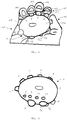
- a handset 1 comprises a housing 2 having an input key 3 for the thumb 102, an input key 4 for the index finger 103, an input key 4 for the middle finger 104, an input key 6 for the ring finger 105 and an input key 7 for the small finger 106 has. Further, the handset 1 has an orientation nub 8 for the root of the index finger 103, an orientation nub 9 for the root of the middle finger 104, an orientation nub 10 for the root of the ring finger 105 and an orientation nub 11 for the root of the small finger 106.
- the handset 1 has a stimulus projection 12, for the reflex zone 112 for the solar plexus, a stimulus projection 13, for the reflex zone 113 for the stomach, a stimulus projection 14 for the reflex zone 116 for the liver and a stimulus projection 15 for the reflex zone 117 for the lungs on.
- the input keys 3 to 7 are designed as pushbuttons. As projecting from the housing 2 and solid projections, the orientation nubs 8 to 11 and the stimulus projections 12 to 15 are formed.
- the housing 2 is ergonomically shaped for holding in the hand 101 in the manner of a flatterer and has the size of about a hen's egg.
- the orientation nubs 8 to 11 engage with the hand 101 with their respective finger roots 108, so that the hand-held device 1 can be easily gripped by the hand 101 with the fingers 102 to 106 and the palm 111.
- the input keys 3 to 7 are arranged relative to the orientation knobs 8 to 11 on the housing such that the input keys 3 to 7 are conveniently pressed by their associated fingers 103 to 106 and the thumb 102 with their respective fingertips 110 and thumb pad 109, respectively can.
- the stimulus projections 12 to 15 are relative to the orientation studs 8 to 11 on the housing 2 arranged such that, when the handset 1 is held in the hand 101, the stimulus projection 12, the reflex zone 112 for the solar plexus, the stimulus projection 13, the reflex zone 113 for the Stomach, the Stimulus projection 14 the reflex zone 114 for the liver and the stimulus projection 15 touches the reflex zone 115 for the lungs.
- FIGs 1 and 2 a first embodiment of the handset 1 is shown, in which the stimulus projections 12 to 15 are formed as local elevations on the housing 2.
- the input keys 3 to 7 are designed as pushbuttons.
- FIG. 3 a second embodiment of the handset 1 is shown.
- the configuration of the input keys 3 to 7 is shown by way of example on the input key 6 for the ring finger 105.
- the input key 6 has a key top 16, which is formed like a cylinder and is mounted longitudinally displaceably in a corresponding guide shaft 17 in the housing.
- the guide shaft 17 is oriented in the housing 2 such that when the key top 16 is pressed with the ring finger 105, the key top 16 in the guide shaft 17 is longitudinally displaced.
- the key top 16 is accessible from outside the housing 2 by the ring finger 105 in that the key top 16 protrudes with its one longitudinal end of the guide shaft 17 and thereby projects from the housing 2.
- a stimulus tip 18 is provided which is touched by the finger tip 110 of the ring finger 105 upon depression of the input key 6. Thereby, the reflex zone 114 for the forehead and head cavities on the ring finger 105 is stimulated.
- a transmission pin 19 is fixed, which is aligned with the key top 16 and extends to a housing opening 21 of the housing 2, the key head 16 together with the transfer pin 19, the housing 2 completely penetrates.
- the key head 16 is formed larger in diameter than the transfer pin 19, a step 20 is formed at the transition from the key top 16 to the transfer pin 19.
- the transfer pin 19 extends in particular when pressed the input button 6 with its longitudinal end 22, the The longitudinal end 22 projects from the housing 2 and forms the stimulus projection 16 for the reflex zone 115 for the lungs.
- the housing opening 21 is formed in a perforated disc 23, which is arranged in the housing 2 concentrically around the transfer pin 19.
- the perforated disc 23 corresponds to the step 20, wherein a first return spring 24 is supported on the step 20 and on the perforated disc 23 and arranged around the transfer pin 1.
- the spring force of the return spring 24 is opposite to the pressure force when pressing the input key 6.
- the fingertip 110 of the ring finger 105 touches the stimulus tip 18.
- the key head 16 moves together with the transfer pin 19 in the guide shaft 17, so that the key head 16 in the guide shaft 17th sunk more and more and the key head 16 facing away from longitudinal end 22 of the transfer pin 19 more and more out of the housing opening 21 protrudes. Since this longitudinal end 22 presses on the palm 111 and thus on the reflex zone 117 for the lungs, acts from the palm 11 a counter force on the transfer pin 19 and the key top 16, which is directed against the pressing force of the ring finger 105.
- FIG. 4 3 a third embodiment of the handset 1 is shown, by way of example the construction of the input key 4 for the index finger 103 is shown.
- the housing 2 has a pin channel 25 in which the Transmission pin 19 is mounted longitudinally displaceable, which extends completely through the housing 2.
- the housing opening 21 is a depressed input button 4, the one longitudinal end 22 of the transfer pin 19 in order to act as a stimulus projection 13 for the reflex zone 113 for the stomach.
- the key top 16 is arranged concentrically around the transfer pin 19, the key top 16 having a housing 2 remote from the key top cover 26.
- a key top opening 27 is provided, through which the other longitudinal end of the transfer pin 19, which is arranged facing away from the housing opening, is extendable.
- the guide shaft 17 accommodates the key top 16, which is larger in diameter than the transmission pin 19, and the transmission pin 19 is arranged in the pin channel 25, the transition from the pin channel 95 to the guide shaft 17 is stepped, whereby a base 29 is present.
- a second return spring 30 is supported on the base 29 and on the inside of the key top 26, so that a restoring force is exerted by the return spring 30 in a non-pressed position of the input key 4 on the key top 16.
- the key top 16 and the transfer pin 19 are freely displaceable to each other.
- the key top 16 When pressing the enter button 4 with the fingertip 110 of the index finger 103, the key top 16 is moved into the guide shaft 17, wherein the transfer pin 19 extends with its longitudinal end 28 through the key top opening 27 and protrudes from the key top 26.
- the reflex zone 114 is stimulated at the fingertip 110 of the index finger 103.
- the transfer pin 19 moves in the pin channel 25, so that the other longitudinal end 22 of the transfer pin 19 from the housing opening 21 more and more extended and the reflex zone 113 for the stomach is irritated.
- the protrusions of the transfer pin 19 at its longitudinal ends 22 and 28 and the friction between the transfer pin 19 and the pin channel 25 and / or the key top 16 and the guide shaft 17 is the degree of irritation of the reflex zone 114 at the fingertip and the reflex zone 113 the palm 111 adjustable.
- the input keys 3 to 7 are connected via signal lines 31 to a data processing unit 32.
- the data processing unit 32 has an input unit 33, with which the data input is controlled, and a memory 34, with which the input data is stored. To operate the data processing unit 32, this has a battery 35 for the power supply.
- the data processing unit 32 has an output unit 36 with which the data stored in the memory 34 can be read out to external devices via an output connection 37.
- the input key 3 is designed as a multi-function key with which seven positions can be switched with the thumb 102.
- the input unit 32 is set up such that, depending on the respective position of the input key 3, the input keys 4 to 7 are assigned to groups of letters of the alphabet.
- the handset 1 serves as a text input device, and with the fingers 103 to 106, input texts 4 to 7 corresponding to the operation of the input key with the thumb 102 can be inputted to texts stored in the storage unit 34 and the output unit 36 via the output port 37 can be read out again.
- the output unit 36 also have a Wlan module with the data via the Internet can be read.
- the handset 1 with its arrangement on the input keys 3 to 7 is constructed so symmetrical that the handset 1 is ambidextrous under the stimulation of the relevant reflex zones 112 to 117 operable, whereby the handset 1 is ambidextrous applicable, ie equivalent Both the right hand and the left hand can be held and operated while the handset 1 is suitable for both a right-handed and a left-hander.
Landscapes
- Engineering & Computer Science (AREA)
- General Engineering & Computer Science (AREA)
- Theoretical Computer Science (AREA)
- Human Computer Interaction (AREA)
- Physics & Mathematics (AREA)
- General Physics & Mathematics (AREA)
- Signal Processing (AREA)
- Push-Button Switches (AREA)
Claims (14)
- Dispositif apte à être tenu à la main pour la saisie de données, ayant une unité de traitement de données (32) et un boîtier (2) qui est moulé ergonomiquement de manière à être tenu dans une main (101) à la façon d'un objet agréable au toucher au niveau de la main (101), ainsi qu'au moins une touche d'entrée (3 à 7) qui est reliée à l'unité de traitement de données (32) pour traiter l'entrée de données par la touche d'entrée (3 à 7), et agencé sur le boîtier (2) de telle sorte que lorsque le dispositif apte à être tenu à la main (1) est tenu à la main (101), les touches d'entrée (3 à 7) sont aptes à être pressées par au moins un des quatre doigts (103 à 106) ou le pouce (102) de la main (101) pour entrer des données, et ainsi une force de pression est apte à être transférée depuis les doigts (103 à 106) ou le pouce (3) à la paume (111) par le dispositif apte à être tenu à la main (1), caractérisé par un emplacement de la surface du boîtier (2) disposé à l'opposé des touches d'entrée (4 à 7) et, lorsque le dispositif apte à être tenu à la main (1) est tenu dans la main (101), est agencé de façon immédiatement adjacente, vers au moins une des zones réflexes (112 à 117) de la paume (111), avec au moins une saillie de stimulation (12 à 15) faisant saillie de l'emplacement de la surface du boîtier (2) qui est disposée de sorte qu'en appuyant sur la touche d'entrée (4 à 7), des terminaisons nerveuses de la zone de réflexologie (112 à 117) sont aptes à être stimulées par la saillie de stimulation (12 à 15), les zones réflexes (112 à 117) affectées à la partie du corps étant stimulées lors de la saisie de données, caractérisé en ce que le boîtier (2), dans l'emplacement de la surface présente une ouverture de logement (21) et le dispositif apte à être tenu à la main (1) comprend une tige de transmission (19) montée mobile, qui est reliée aux touches d'entrée (3 à 7), de sorte que, lorsque la touche d'entrée (3 à 7) est pressée, la tige de transmission (19) s'étend à travers l'ouverture de boîtier (21) par une extrémité longitudinale (22) et fait saillie depuis l'emplacement de la surface, de sorte que l'extrémité longitudinale (22) forme la saillie de stimulation (12 à 15).
- Dispositif apte à être tenu à la main selon la revendication 1, dans lequel le boîtier (2) présente, au niveau d'au moins l'une des racines (108) par lesquelles lesdits doigts (103 à 106) sont articulés à la paume (111), des boutons d'orientation (9 à 11) associés aux doigts (103 à 106), qui sont agencés de telle sorte que, lorsque le dispositif apte à être tenu à la main (1) est tenu dans la dans la main (101), les boutons d'orientation (9 à 11) soient en engagement avec les racines (108) associées et la saillie de stimulation (12 à 15) soit apte à venir en contact avec la zone réflexe (112 à 117) associée, en contact par effleurement et la touche d'entrée (3 à 7) soit pressée par son doigt (103 à 106) / pouce (102) associé.
- Dispositif apte à être tenu à la main selon la revendication 1 ou la revendication 2, dans lequel le bout du doigt (110) / le bout du pouce (109) saisit et presse la touche d'entrée associée au doigt (103 à 106) / au pouce (102).
- Dispositif apte à être tenu à la main selon l'une quelconque des revendications 1 à 3, dans lequel la tige de transmission (19) est dimensionnée pour être stockée et est couplée à la touche d'entrée (3 à 7), de sorte que, lorsque la touche d'entrée (3 à 7) n'est pas pressée, l'extrémité longitudinale (22) de la tige de transmission (19) est enfoncée dans l'ouverture de boîtier (21).
- Dispositif apte à être tenu à la main selon l'une des revendications 1 à 4, dans lequel la touche d'entrée (3 à 7) comprend une partie supérieure de touche (16) mobile, permettant de presser la touche d'entrée (3 à 7), qui est fixée à la tige de transmission (19), dans le prolongement de celle-ci, de sorte que la partie supérieure de touche (16) pénètre complètement dans le boîtier (2), avec la tige de transmission (19).
- Dispositif apte à être tenu à la main selon la revendication 5, dans lequel la partie supérieure de touche (16) présente une pointe (18) faisant saillie du boîtier (2), de sorte que le doigt (103 à 106) / le pouce (103) est stimulé lorsqu'il appuie sur la touche d'entrée (3 à 7).
- Dispositif apte à être tenu à la main selon l'une des revendications 1 à 4, dans lequel la touche d'entrée (3 à 7) comporte une partie supérieure de touche (16) mobile pour appuyer sur la touche d'entrée (3 à 7) et la tige de transmission (19) pénètre entièrement dans le boîtier (2), et s'étend dans la partie supérieure de touche (16), de sorte que, lorsque la touche d'entrée est de (3 à 7) est pressée, l'extrémité longitudinale (28) de la tige de transmission (19), qui est disposée à l'opposé de l'ouverture de boîtier (21), s'étend à travers une ouverture (27) de la partie supérieure de touche (16) et fait saillie de la tête de touche (16), de sorte que les doigts (103 à 106) / le pouce (102) sont stimulés lorsque l'on appuie sur la touche d'entrée (3 à 7).
- Dispositif apte à être tenu à la main selon l'une quelconque des revendications 5 à 7, dans lequel le dispositif apte à être tenu à la main (1) comprend un moyen de sollicitation (24, 30) qui coopère avec la partie supérieure de touche (16) et qui, au moyen de sa force de pression contrecarrant la force de rappel de la partie supérieure de touche (16), entraîne celle-ci dans sa position non enfoncée, les moyens de sollicitation (24, 30) étant dimensionnés de telle sorte que les résultats de la force de sollicitation, par l'intensité de la force de compression, stimule la zones réflexes (112 à 117) affectées à la partie du corps lors de la saisie de données pour une relaxation, le soulagement d'une douleur ou pour guérir une maladie.
- Dispositif apte à être tenu à la main selon l'une quelconque des revendications 1 à 8, dans lequel la tige de transmission (19) est de forme arquée.
- Dispositif apte à être tenu à la main selon l'une quelconque des revendications 1 à 9, dans lequel le dispositif apte à être tenu à la main (1), comprend une touche d'entrée (4-7) pour chacun des quatre doigts (103 à 106) de chacune des touches d'entrée et une touche d'entrée supplémentaire (3) pour le pouce (102), qui est conçue comme un bouton multifonction, les différentes fonctionnalités des touches d'entrée (4-7) étant commutables pour les doigts (103 à 106).
- Dispositif apte à être tenu à la main selon l'une quelconque des revendications 1 à 10, dans lequel l'unité de traitement de données (32) comprend une mémoire (34) qui permet de mémoriser les données entrées avec les touches d'entrée (3 à 7).
- Dispositif de commande à distance pour commander à distance un dispositif comprenant un dispositif apte à être tenu à la main (1) selon l'une quelconque des revendications 1 à 11.
- Téléphone portable ayant un dispositif apte à être tenu à la main (1) selon l'une quelconque des revendications 1 à 11.
- Dispositif de jeu avec un dispositif apte à être tenu à la main (1) selon l'une quelconque des revendications 1 à 11.
Priority Applications (2)
| Application Number | Priority Date | Filing Date | Title |
|---|---|---|---|
| EP14166403.7A EP2940974B1 (fr) | 2014-04-29 | 2014-04-29 | Dispositif portable pour une saisie de données ainsi que la télécommande, téléphone mobile et console de jeu. |
| PCT/EP2015/059215 WO2015165907A1 (fr) | 2014-04-29 | 2015-04-28 | Dispositif portatif d'entrée de données ainsi que dispositif de commande à distance, téléphone mobile et dispositif de jeu |
Applications Claiming Priority (1)
| Application Number | Priority Date | Filing Date | Title |
|---|---|---|---|
| EP14166403.7A EP2940974B1 (fr) | 2014-04-29 | 2014-04-29 | Dispositif portable pour une saisie de données ainsi que la télécommande, téléphone mobile et console de jeu. |
Publications (2)
| Publication Number | Publication Date |
|---|---|
| EP2940974A1 EP2940974A1 (fr) | 2015-11-04 |
| EP2940974B1 true EP2940974B1 (fr) | 2017-01-11 |
Family
ID=50679862
Family Applications (1)
| Application Number | Title | Priority Date | Filing Date |
|---|---|---|---|
| EP14166403.7A Not-in-force EP2940974B1 (fr) | 2014-04-29 | 2014-04-29 | Dispositif portable pour une saisie de données ainsi que la télécommande, téléphone mobile et console de jeu. |
Country Status (2)
| Country | Link |
|---|---|
| EP (1) | EP2940974B1 (fr) |
| WO (1) | WO2015165907A1 (fr) |
Family Cites Families (3)
| Publication number | Priority date | Publication date | Assignee | Title |
|---|---|---|---|---|
| US4905001A (en) * | 1987-10-08 | 1990-02-27 | Penner Henry C | Hand-held finger movement actuated communication devices and systems employing such devices |
| US6762749B1 (en) * | 1997-01-09 | 2004-07-13 | Virtouch Ltd. | Tactile interface system for electronic data display system |
| DE102004042884B4 (de) * | 2004-09-04 | 2009-09-24 | Hönicke, Bernd | Kommunikationsgerät für sinnesbehinderte Personen |
-
2014
- 2014-04-29 EP EP14166403.7A patent/EP2940974B1/fr not_active Not-in-force
-
2015
- 2015-04-28 WO PCT/EP2015/059215 patent/WO2015165907A1/fr not_active Ceased
Non-Patent Citations (1)
| Title |
|---|
| None * |
Also Published As
| Publication number | Publication date |
|---|---|
| WO2015165907A1 (fr) | 2015-11-05 |
| EP2940974A1 (fr) | 2015-11-04 |
Similar Documents
| Publication | Publication Date | Title |
|---|---|---|
| DE60001107T2 (de) | Sichere und handliche hinweisanordung | |
| EP0920673B1 (fr) | Procede et dispositif pour introduire des donnees d'une seule main | |
| DE102010052759A1 (de) | Geräteanordnung zur Simulation der gegenseitigen Berührung zweier Menschen aus der Ferne | |
| DE4400790A1 (de) | Vorrichtung und/oder Verfahren zur Kommunikation mit DV-Anlagen bzw. Bedienungsvorrichtungen | |
| EP3787566A1 (fr) | Orthèse de doigt et procédé pour sa fabrication | |
| DE102009023579B4 (de) | Tastfeld-Vorrichtung | |
| EP2940974B1 (fr) | Dispositif portable pour une saisie de données ainsi que la télécommande, téléphone mobile et console de jeu. | |
| DE60210092T2 (de) | Tastatur | |
| EP0809223B1 (fr) | Dispositif de transmission de signes et de caractères d'un système de traitement de données à une personne sourde/aveugle | |
| DE3889352T2 (de) | Dateneingabesystem für einen Rechner. | |
| WO2006024554A2 (fr) | Unite d'entree mecanique pour unite de visualisation a surface a affleurement | |
| DE102022134798B4 (de) | Passives Akupressurgerät | |
| KR200188851Y1 (ko) | 컴퓨터 조작용 마우스 | |
| DE102008018194A1 (de) | Pad zur permanent beidhändigen Entlastung von Handgelenk und Unterarm | |
| DE29513538U1 (de) | Fernbedienung für ein Elektrogerät | |
| DE102011052331B4 (de) | Schreibgerät mit mechanischer Korrektur der Klemmkräfte | |
| DE102013105663A1 (de) | Touch-Eingabegerät | |
| DE102008058196A1 (de) | Mehrfunktions- oder Flachmaus für neue, handschonende und leistungssteigernde Computermaus für PC's, Laptops und elektronische Steuergeräte | |
| WO2017162712A1 (fr) | Dispositif de saisie sous forme de clavier à une main | |
| DE3521508A1 (de) | Lochtaste | |
| DE10127589A1 (de) | Bedienelement für Computer oder dergleichen | |
| CN2655333Y (zh) | 新型普通键盘 | |
| DE102004035143A1 (de) | Vorrichtung zur Umwandlung einer Handbewegung in eine elektrische Signalfolge | |
| DE202018003538U1 (de) | Fernbedienung | |
| DE202020005659U1 (de) | Elektrisches Handgerät |
Legal Events
| Date | Code | Title | Description |
|---|---|---|---|
| PUAI | Public reference made under article 153(3) epc to a published international application that has entered the european phase |
Free format text: ORIGINAL CODE: 0009012 |
|
| 17P | Request for examination filed |
Effective date: 20150223 |
|
| AK | Designated contracting states |
Kind code of ref document: A1 Designated state(s): AL AT BE BG CH CY CZ DE DK EE ES FI FR GB GR HR HU IE IS IT LI LT LU LV MC MK MT NL NO PL PT RO RS SE SI SK SM TR |
|
| AX | Request for extension of the european patent |
Extension state: BA ME |
|
| GRAP | Despatch of communication of intention to grant a patent |
Free format text: ORIGINAL CODE: EPIDOSNIGR1 |
|
| INTG | Intention to grant announced |
Effective date: 20160727 |
|
| GRAS | Grant fee paid |
Free format text: ORIGINAL CODE: EPIDOSNIGR3 |
|
| GRAA | (expected) grant |
Free format text: ORIGINAL CODE: 0009210 |
|
| AK | Designated contracting states |
Kind code of ref document: B1 Designated state(s): AL AT BE BG CH CY CZ DE DK EE ES FI FR GB GR HR HU IE IS IT LI LT LU LV MC MK MT NL NO PL PT RO RS SE SI SK SM TR |
|
| REG | Reference to a national code |
Ref country code: GB Ref legal event code: FG4D Free format text: NOT ENGLISH |
|
| REG | Reference to a national code |
Ref country code: CH Ref legal event code: EP |
|
| REG | Reference to a national code |
Ref country code: AT Ref legal event code: REF Ref document number: 862206 Country of ref document: AT Kind code of ref document: T Effective date: 20170115 |
|
| REG | Reference to a national code |
Ref country code: IE Ref legal event code: FG4D Free format text: LANGUAGE OF EP DOCUMENT: GERMAN |
|
| REG | Reference to a national code |
Ref country code: DE Ref legal event code: R096 Ref document number: 502014002447 Country of ref document: DE |
|
| REG | Reference to a national code |
Ref country code: FR Ref legal event code: PLFP Year of fee payment: 4 |
|
| REG | Reference to a national code |
Ref country code: LT Ref legal event code: MG4D |
|
| REG | Reference to a national code |
Ref country code: NL Ref legal event code: MP Effective date: 20170111 |
|
| PG25 | Lapsed in a contracting state [announced via postgrant information from national office to epo] |
Ref country code: NL Free format text: LAPSE BECAUSE OF FAILURE TO SUBMIT A TRANSLATION OF THE DESCRIPTION OR TO PAY THE FEE WITHIN THE PRESCRIBED TIME-LIMIT Effective date: 20170111 |
|
| PG25 | Lapsed in a contracting state [announced via postgrant information from national office to epo] |
Ref country code: IS Free format text: LAPSE BECAUSE OF FAILURE TO SUBMIT A TRANSLATION OF THE DESCRIPTION OR TO PAY THE FEE WITHIN THE PRESCRIBED TIME-LIMIT Effective date: 20170511 Ref country code: HR Free format text: LAPSE BECAUSE OF FAILURE TO SUBMIT A TRANSLATION OF THE DESCRIPTION OR TO PAY THE FEE WITHIN THE PRESCRIBED TIME-LIMIT Effective date: 20170111 Ref country code: LT Free format text: LAPSE BECAUSE OF FAILURE TO SUBMIT A TRANSLATION OF THE DESCRIPTION OR TO PAY THE FEE WITHIN THE PRESCRIBED TIME-LIMIT Effective date: 20170111 Ref country code: GR Free format text: LAPSE BECAUSE OF FAILURE TO SUBMIT A TRANSLATION OF THE DESCRIPTION OR TO PAY THE FEE WITHIN THE PRESCRIBED TIME-LIMIT Effective date: 20170412 Ref country code: NO Free format text: LAPSE BECAUSE OF FAILURE TO SUBMIT A TRANSLATION OF THE DESCRIPTION OR TO PAY THE FEE WITHIN THE PRESCRIBED TIME-LIMIT Effective date: 20170411 Ref country code: FI Free format text: LAPSE BECAUSE OF FAILURE TO SUBMIT A TRANSLATION OF THE DESCRIPTION OR TO PAY THE FEE WITHIN THE PRESCRIBED TIME-LIMIT Effective date: 20170111 |
|
| PG25 | Lapsed in a contracting state [announced via postgrant information from national office to epo] |
Ref country code: LV Free format text: LAPSE BECAUSE OF FAILURE TO SUBMIT A TRANSLATION OF THE DESCRIPTION OR TO PAY THE FEE WITHIN THE PRESCRIBED TIME-LIMIT Effective date: 20170111 Ref country code: BG Free format text: LAPSE BECAUSE OF FAILURE TO SUBMIT A TRANSLATION OF THE DESCRIPTION OR TO PAY THE FEE WITHIN THE PRESCRIBED TIME-LIMIT Effective date: 20170411 Ref country code: RS Free format text: LAPSE BECAUSE OF FAILURE TO SUBMIT A TRANSLATION OF THE DESCRIPTION OR TO PAY THE FEE WITHIN THE PRESCRIBED TIME-LIMIT Effective date: 20170111 Ref country code: PT Free format text: LAPSE BECAUSE OF FAILURE TO SUBMIT A TRANSLATION OF THE DESCRIPTION OR TO PAY THE FEE WITHIN THE PRESCRIBED TIME-LIMIT Effective date: 20170511 Ref country code: SE Free format text: LAPSE BECAUSE OF FAILURE TO SUBMIT A TRANSLATION OF THE DESCRIPTION OR TO PAY THE FEE WITHIN THE PRESCRIBED TIME-LIMIT Effective date: 20170111 Ref country code: ES Free format text: LAPSE BECAUSE OF FAILURE TO SUBMIT A TRANSLATION OF THE DESCRIPTION OR TO PAY THE FEE WITHIN THE PRESCRIBED TIME-LIMIT Effective date: 20170111 Ref country code: PL Free format text: LAPSE BECAUSE OF FAILURE TO SUBMIT A TRANSLATION OF THE DESCRIPTION OR TO PAY THE FEE WITHIN THE PRESCRIBED TIME-LIMIT Effective date: 20170111 |
|
| REG | Reference to a national code |
Ref country code: DE Ref legal event code: R097 Ref document number: 502014002447 Country of ref document: DE |
|
| PG25 | Lapsed in a contracting state [announced via postgrant information from national office to epo] |
Ref country code: IT Free format text: LAPSE BECAUSE OF FAILURE TO SUBMIT A TRANSLATION OF THE DESCRIPTION OR TO PAY THE FEE WITHIN THE PRESCRIBED TIME-LIMIT Effective date: 20170111 Ref country code: EE Free format text: LAPSE BECAUSE OF FAILURE TO SUBMIT A TRANSLATION OF THE DESCRIPTION OR TO PAY THE FEE WITHIN THE PRESCRIBED TIME-LIMIT Effective date: 20170111 Ref country code: SK Free format text: LAPSE BECAUSE OF FAILURE TO SUBMIT A TRANSLATION OF THE DESCRIPTION OR TO PAY THE FEE WITHIN THE PRESCRIBED TIME-LIMIT Effective date: 20170111 Ref country code: RO Free format text: LAPSE BECAUSE OF FAILURE TO SUBMIT A TRANSLATION OF THE DESCRIPTION OR TO PAY THE FEE WITHIN THE PRESCRIBED TIME-LIMIT Effective date: 20170111 Ref country code: CZ Free format text: LAPSE BECAUSE OF FAILURE TO SUBMIT A TRANSLATION OF THE DESCRIPTION OR TO PAY THE FEE WITHIN THE PRESCRIBED TIME-LIMIT Effective date: 20170111 |
|
| PLBE | No opposition filed within time limit |
Free format text: ORIGINAL CODE: 0009261 |
|
| STAA | Information on the status of an ep patent application or granted ep patent |
Free format text: STATUS: NO OPPOSITION FILED WITHIN TIME LIMIT |
|
| PG25 | Lapsed in a contracting state [announced via postgrant information from national office to epo] |
Ref country code: DK Free format text: LAPSE BECAUSE OF FAILURE TO SUBMIT A TRANSLATION OF THE DESCRIPTION OR TO PAY THE FEE WITHIN THE PRESCRIBED TIME-LIMIT Effective date: 20170111 Ref country code: SM Free format text: LAPSE BECAUSE OF FAILURE TO SUBMIT A TRANSLATION OF THE DESCRIPTION OR TO PAY THE FEE WITHIN THE PRESCRIBED TIME-LIMIT Effective date: 20170111 |
|
| REG | Reference to a national code |
Ref country code: CH Ref legal event code: PL |
|
| 26N | No opposition filed |
Effective date: 20171012 |
|
| REG | Reference to a national code |
Ref country code: IE Ref legal event code: MM4A |
|
| PG25 | Lapsed in a contracting state [announced via postgrant information from national office to epo] |
Ref country code: MC Free format text: LAPSE BECAUSE OF FAILURE TO SUBMIT A TRANSLATION OF THE DESCRIPTION OR TO PAY THE FEE WITHIN THE PRESCRIBED TIME-LIMIT Effective date: 20170111 |
|
| PG25 | Lapsed in a contracting state [announced via postgrant information from national office to epo] |
Ref country code: LI Free format text: LAPSE BECAUSE OF NON-PAYMENT OF DUE FEES Effective date: 20170430 Ref country code: CH Free format text: LAPSE BECAUSE OF NON-PAYMENT OF DUE FEES Effective date: 20170430 Ref country code: LU Free format text: LAPSE BECAUSE OF NON-PAYMENT OF DUE FEES Effective date: 20170429 Ref country code: SI Free format text: LAPSE BECAUSE OF FAILURE TO SUBMIT A TRANSLATION OF THE DESCRIPTION OR TO PAY THE FEE WITHIN THE PRESCRIBED TIME-LIMIT Effective date: 20170111 |
|
| REG | Reference to a national code |
Ref country code: BE Ref legal event code: MM Effective date: 20170430 |
|
| REG | Reference to a national code |
Ref country code: FR Ref legal event code: PLFP Year of fee payment: 5 |
|
| PG25 | Lapsed in a contracting state [announced via postgrant information from national office to epo] |
Ref country code: IE Free format text: LAPSE BECAUSE OF NON-PAYMENT OF DUE FEES Effective date: 20170429 |
|
| PG25 | Lapsed in a contracting state [announced via postgrant information from national office to epo] |
Ref country code: BE Free format text: LAPSE BECAUSE OF NON-PAYMENT OF DUE FEES Effective date: 20170430 |
|
| PG25 | Lapsed in a contracting state [announced via postgrant information from national office to epo] |
Ref country code: MT Free format text: LAPSE BECAUSE OF FAILURE TO SUBMIT A TRANSLATION OF THE DESCRIPTION OR TO PAY THE FEE WITHIN THE PRESCRIBED TIME-LIMIT Effective date: 20170111 |
|
| PG25 | Lapsed in a contracting state [announced via postgrant information from national office to epo] |
Ref country code: HU Free format text: LAPSE BECAUSE OF FAILURE TO SUBMIT A TRANSLATION OF THE DESCRIPTION OR TO PAY THE FEE WITHIN THE PRESCRIBED TIME-LIMIT; INVALID AB INITIO Effective date: 20140429 |
|
| PGFP | Annual fee paid to national office [announced via postgrant information from national office to epo] |
Ref country code: DE Payment date: 20190430 Year of fee payment: 6 |
|
| PGFP | Annual fee paid to national office [announced via postgrant information from national office to epo] |
Ref country code: FR Payment date: 20190521 Year of fee payment: 6 |
|
| PG25 | Lapsed in a contracting state [announced via postgrant information from national office to epo] |
Ref country code: CY Free format text: LAPSE BECAUSE OF FAILURE TO SUBMIT A TRANSLATION OF THE DESCRIPTION OR TO PAY THE FEE WITHIN THE PRESCRIBED TIME-LIMIT Effective date: 20170111 |
|
| PGFP | Annual fee paid to national office [announced via postgrant information from national office to epo] |
Ref country code: GB Payment date: 20190523 Year of fee payment: 6 |
|
| PG25 | Lapsed in a contracting state [announced via postgrant information from national office to epo] |
Ref country code: MK Free format text: LAPSE BECAUSE OF FAILURE TO SUBMIT A TRANSLATION OF THE DESCRIPTION OR TO PAY THE FEE WITHIN THE PRESCRIBED TIME-LIMIT Effective date: 20170111 |
|
| PG25 | Lapsed in a contracting state [announced via postgrant information from national office to epo] |
Ref country code: TR Free format text: LAPSE BECAUSE OF FAILURE TO SUBMIT A TRANSLATION OF THE DESCRIPTION OR TO PAY THE FEE WITHIN THE PRESCRIBED TIME-LIMIT Effective date: 20170111 |
|
| PG25 | Lapsed in a contracting state [announced via postgrant information from national office to epo] |
Ref country code: AL Free format text: LAPSE BECAUSE OF FAILURE TO SUBMIT A TRANSLATION OF THE DESCRIPTION OR TO PAY THE FEE WITHIN THE PRESCRIBED TIME-LIMIT Effective date: 20170111 |
|
| REG | Reference to a national code |
Ref country code: AT Ref legal event code: MM01 Ref document number: 862206 Country of ref document: AT Kind code of ref document: T Effective date: 20190429 |
|
| REG | Reference to a national code |
Ref country code: DE Ref legal event code: R119 Ref document number: 502014002447 Country of ref document: DE |
|
| PG25 | Lapsed in a contracting state [announced via postgrant information from national office to epo] |
Ref country code: AT Free format text: LAPSE BECAUSE OF NON-PAYMENT OF DUE FEES Effective date: 20190429 |
|
| PG25 | Lapsed in a contracting state [announced via postgrant information from national office to epo] |
Ref country code: FR Free format text: LAPSE BECAUSE OF NON-PAYMENT OF DUE FEES Effective date: 20200430 Ref country code: DE Free format text: LAPSE BECAUSE OF NON-PAYMENT OF DUE FEES Effective date: 20201103 |
|
| GBPC | Gb: european patent ceased through non-payment of renewal fee |
Effective date: 20200429 |
|
| PG25 | Lapsed in a contracting state [announced via postgrant information from national office to epo] |
Ref country code: GB Free format text: LAPSE BECAUSE OF NON-PAYMENT OF DUE FEES Effective date: 20200429 |