EP2942237A1 - Vorrichtung zur verankerung einer extremität einer dachreling für ein kraftfahrzeug, das mit längs-dachrelingen ausgestattet ist - Google Patents
Vorrichtung zur verankerung einer extremität einer dachreling für ein kraftfahrzeug, das mit längs-dachrelingen ausgestattet ist Download PDFInfo
- Publication number
- EP2942237A1 EP2942237A1 EP15165290.6A EP15165290A EP2942237A1 EP 2942237 A1 EP2942237 A1 EP 2942237A1 EP 15165290 A EP15165290 A EP 15165290A EP 2942237 A1 EP2942237 A1 EP 2942237A1
- Authority
- EP
- European Patent Office
- Prior art keywords
- bar
- longitudinal
- anchoring
- longitudinal bar
- roof
- Prior art date
- Legal status (The legal status is an assumption and is not a legal conclusion. Google has not performed a legal analysis and makes no representation as to the accuracy of the status listed.)
- Granted
Links
Images
Classifications
-
- B—PERFORMING OPERATIONS; TRANSPORTING
- B60—VEHICLES IN GENERAL
- B60R—VEHICLES, VEHICLE FITTINGS, OR VEHICLE PARTS, NOT OTHERWISE PROVIDED FOR
- B60R9/00—Supplementary fittings on vehicle exterior for carrying loads, e.g. luggage, sports gear or the like
- B60R9/04—Carriers associated with vehicle roof
- B60R9/052—Carriers comprising elongate members extending only transversely of vehicle
-
- B—PERFORMING OPERATIONS; TRANSPORTING
- B60—VEHICLES IN GENERAL
- B60R—VEHICLES, VEHICLE FITTINGS, OR VEHICLE PARTS, NOT OTHERWISE PROVIDED FOR
- B60R9/00—Supplementary fittings on vehicle exterior for carrying loads, e.g. luggage, sports gear or the like
- B60R9/04—Carriers associated with vehicle roof
- B60R9/058—Carriers associated with vehicle roof characterised by releasable attaching means between carrier and roof
Definitions
- the invention relates to devices for anchoring an end of a roof bar (or crossbar) on a longitudinal bar secured to an upper side portion of a motor vehicle structure.
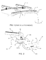
- upper lateral part of a motor vehicle structure is meant here the structural part which delimits the lateral part of the roof (or roof) on one of the two lateral (or longitudinal) sides of a motor vehicle and which located at the level of the upper part of a side door (see figure 1 ).
- motor vehicles 1 comprise a structure whose two opposite upper lateral parts 2 are equipped with a longitudinal bar 3.
- Each longitudinal bar 3 generally has a cross section of varied shape and is secured to one of the two upper lateral parts 3 by welding or screwing.
- the roof bars 4 are accessories that are adapted to be reported between the two longitudinal bars 3 and fixed on these bars via anchoring devices 5 which must generally be previously mounted on the ends of the roof bars.
- the roof bars 4 are used to support different types of objects such as a roof box, surf bike racks, skis, etc.
- the device comprises, on the free end of the roof bar, a fixed jaw and a movable jaw disposed opposite the fixed part being movable in translation relative to the fixed part, the jaws being adapted to at least partially enclose a section of the longitudinal bar, and clamping means of the jaws on the longitudinal bar.
- the transverse bars can be arranged in different configurations along the longitudinal bars.
- Blocking in position is ensured by simply pinching the longitudinal bar between the two jaws.
- This device does not guarantee optimum shock resistance and tear resistance in accordance with the standards in force.
- the invention aims to provide an anchoring device for securely fixing a roof bar end on a longitudinal bar secured to an upper side portion of a motor vehicle structure.
- a device for anchoring a roof bar end on a longitudinal bar secured to an upper lateral part of a vehicle structure part substantially parallel to a longitudinal direction of the latter said device comprising a fixed jaw and a movable jaw disposed facing the fixed jaw being movable relative to the fixed jaw to be able to grip at least partially a section of the longitudinal bar, and clamping means of the movable jaw on the longitudinal bar
- the device being characterized in that it comprises at least first anchoring means comprising at least one body secured to the roof bar ending in a first nozzle defining a bearing surface of the fixed jaw substantially conforming to the shape of the longitudinal bar, said body supporting displacement of the movable jaw, one end protrudes from the body s to come opposite the first nozzle, and in that the device comprises at least second anchoring means comprising means forming a stop, formed on or in the longitudinal bar; the end portion of the second nose of the first anchoring means being shaped to be adapted to cooperating with said abutment second anchoring means under
- the body rotatably supports a lever defining the movable jaw and whose displacement is rotated about a fixed fulcrum of the body under the effect of the clamping means.
- the clamping means comprise a screw whose head is abutting on the roof bar and whose threaded portion cooperates with a nut means coupled in rotation with the lever.
- the body supports in translation a jaw defining the movable jaw and whose displacement is in translation in the body under the effect of the clamping means.
- the cross section of the longitudinal bar is delimited by a flat inner edge, extending by an adjacent lower plane edge, and a partially convex upper edge connecting the lower edge to the inner edge.
- the bearing surface of the first nozzle is shaped to be able to fit at least partially the inner edge and the upper edge of the longitudinal bar, and in that the second nozzle is shaped to be able to conform to less partially the lower edge of the longitudinal bar; the end portion of the second nozzle being bent to be able to cooperate with a stop formed in the lower edge of the longitudinal bar.
- the stop defines a generally rectangular counterbore whose large dimension extends in the longitudinal direction, centered on the lower edge of the longitudinal bar.
- the invention also proposes a roof bar comprising an access opening for the clamping means of the anchoring device as described above.
- the invention also proposes a longitudinal bar capable of being secured to an upper lateral part of a vehicle structure part, substantially parallel to a longitudinal direction of the latter, comprising a stop corresponding to that of the second anchoring means of the anchoring device as described above.
- the invention also provides a body adapted to be secured to the end of a roof bar as described above, said body belonging to the first anchoring means of the anchoring device as described above.
- the invention also proposes a motor vehicle comprising at least one pair of longitudinal bars as described above, at least one roof bar as described above and an anchoring device as described above.
- the motor vehicle is a car (possibly cut type). But, the invention is not limited to this type of motor vehicle. It relates in fact to any type of motor vehicle having a roof defined at each of its opposite lateral parts by an upper side of the structure to which is secured in a robust manner a pair of longitudinal bars.
- longitudinal direction X the direction which is substantially parallel to the side doors of the vehicle and therefore to the upper lateral parts of the structure
- transverse direction Y the direction which is substantially perpendicular to the side doors of the vehicle and therefore to the longitudinal direction X
- vertical direction Z the direction which is substantially perpendicular to the longitudinal direction X and transverse Y.
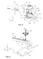
- the cross section of the longitudinal bar 30, visible on the figures 2 , 5 and 6 is delimited by an inner edge 31 substantially flat and vertical, extending by an adjacent lower flat edge 32, extending relative to the vertical inner edge 31 towards the outside of the vehicle 1 with an angle of between 90 ° and 110 ° , typically 105 °, relative to the vertical inner edge 31, and an upper edge 33 connecting the lower edge 32 to the inner edge 31.
- This edge 33 is first convex, opposite the inner edge 31, and then gradually becomes parallel at the lower edge 32 by approaching the inner edge 31 in the manner of a so-called "airfoil" profile.
- an anchoring device 50 which comprises first and second anchoring means 50A, 50B respectively distributed on the roof bar 40 and on the longitudinal bar 30.
- the main body 51 of the first anchoring means 50A of the anchoring device 50 is mounted in translation on a guide rail 41 formed on the inner face of the end of the roof bar 40.
- This rail 41 of determined length and open towards the outside of the bar 40, makes it possible to adjust the first anchoring means 50A to the spacing between the two longitudinal bars 30.
- the outer part of the main body 51, along Y, (right in the figures) defines a fixed jaw 52 whose free end is shaped as a first spout 53, to be able to fit at least partially the vertical inner edge 31 and the upper edge 33 of the longitudinal bar 30.
- the main body 51 rotatably supports a movable jaw 54 whose free end is shaped to define a second spout 55, facing the first spout 53.
- the movable jaw 54 is preferably metallic in order to be able to withstand the mechanical stresses, in particular of tearing and impact.
- the end portion of the second spout 55 is bent in the shape of a hook 56 so as to be able to cooperate with the second anchoring means 50B arranged under the longitudinal bar 30.
- These second anchoring means 50B according to the invention are materialized by an opening 34 formed in the lower edge 32 of the longitudinal bar 30 having at least two longitudinal stops and at least two transverse stops capable of ensuring the locking X and Y of the roof bar 40 on the longitudinal bar 30.
- the opening 34 defines a rectangular generally oblong facing, the large dimension of which extends in the longitudinal direction X, being centered on the lower edge 32 of the longitudinal bar 30. edges of the countersink 34 define stops for the bent portion 56 of the second spout 55.
- the opening may be replaced by at least one protuberance formed integrally with the lower edge 32 of the longitudinal bar 30 to define a stop X, projecting under the lower edge 32 of the longitudinal bar 30.
- a piece of flexible material 60 is attached inside the first spout 53 to protect the longitudinal bar 30 and absorb vibration.
- This piece 60 extends outside the second spout 55, downwards, along Z, towards the end of the second spout 55, to define a flat tongue 61 of greater width than that of the end of the second spout 55 .
- the length of the tongue 61 is determined to be able to interpose between the second spout 55 and the lower edge 32 of the longitudinal bar 30 when the roof bar 40 is assembled on the longitudinal bar 30.
- the free end of the tongue 61 is provided with an opening 62 of generally rectangular or oblong shape, adapted to be disposed facing the counterbore 34 of the longitudinal bar 30 and to be traversed from side to side. part by the curved portion 56 of the second spout 55, at the time of clamping the movable jaw 54 against the longitudinal bar 30.
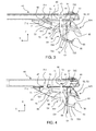
- a movable jaw clamping mechanism 54 is hereinafter described with reference to Figures 3 to 6 .
- the movable jaw portion 54 comprises a lever 70, extending inside the body 51 in the YZ plane, the two lever arms 71 and 72 extend in two opposite directions along Y, on either side of a fixed fulcrum 73 materialized by a projection protruding inside the upper part of the body 51.
- the first short arm 71 is disposed to the left of the fixed fulcrum 73 and the second, long arm 72 terminating in the second curved end plate 55 is disposed to the right of the fixed fulcrum 73 , referring to the orientation of Figures 3 to 6 .
- the second arm 72 comprises, starting from the fixed support point 73, a first section 721 extending in a first direction deviating substantially from an angle of approximately 10 ° from the horizontal direction along Y to the lower part of the body 51.
- the first section 721 is extended by a second section 722 of the same length, via a first bent portion 720, extending in a second direction deviating substantially from an angle of about 10 ° of the vertical direction along Z, to the outer part of the body 51 (to the right in the figures).
- the second section 722 is extended by a third section 723 extending in the same first direction, via a second bent portion 724, with the same angle with respect to the horizontal direction along Y, towards the lower part of the body 51.
- the third section 723 protrudes from the lower part of the body 51 and defines the second spout 55, able to come into contact with the lower edge 32 of the longitudinal bar 30.
- the free end 710 of the first lever arm 71 protrudes from the upper part of the body 51 through an opening 42 which is driven close to the fixed bearing point 73 (to the left of the fixed fulcrum). 73 in the figures). This opening 42 can wedge the lever 70 in the X and Y directions.
- the lever 70 (and thus the movable jaw 54) is held suspended in the body 51 by a screw 80 passing right through an opening 57 formed in the upper wall of the body 51, opposite the first bent portion 720 of the second arm lever 72.
- the screw head 81 hexagonal hollow or Torx type (the Torx screw is a solution to limit the risk of theft), is supported on the rail guide 41 and its threaded portion 82 through the opening 57 formed in the upper wall of the body 51.
- the lower end of the threaded portion 82 of the screw 80 cooperates with a threaded hole 90 of vertical axis Z, forming a nut , formed in a cylindrical rod 91 of circular section extending along X.
- the rod 91 is rotatably mounted in the first bent portion 720 of the second arm 72 to form a pivot connection.
- the assembly consisting of the threaded portion 82 and the nut-rod 90-91 form a worm system (helical linkage) and the mechanical connection between the rod 90 and the second arm 72 forms a pivot-type connection.
- the combination of the helical and pivot mechanical links defines a second fulcrum for the lever 70.
- the tightening of the screw 80 causes the second lever arm 72 upwards along Z, which pivots around the first fulcrum 73 anti-clockwise; the pivoting being authorized by the pivot connection.
- the screw head 81 is accessible through an opening 43 formed in the upper face of the roof bar 40, facing the screw head 80.
- the dimensions of the opening 43 are determined to take account of the movement of the body X 51 of the anchoring device on the rail 41 of the roof bar 40.
- the rotational movement of the second lever arm 72 is limited, in the lower part of the body 51, by two vertical walls or ribs 58 and 59, integral with the body 51 to define respectively two travel stops for the second section 722. second lever arm 72.
- the tightening of the screw 80 makes it possible to bring the second spout 55 closer to the lower edge 32 of the longitudinal bar 30 ensuring the introduction of the part curved end 56 of the second spout 55 inside the countersink 34 of the longitudinal bar 30.
- the movable jaw 54 then defines a movable jaw like that of a vice, the nut being then a simple tapped hole inside the bit. The fulcrum is then no longer necessary.
Landscapes
- Engineering & Computer Science (AREA)
- Mechanical Engineering (AREA)
- Body Structure For Vehicles (AREA)
- Dowels (AREA)
Applications Claiming Priority (1)
| Application Number | Priority Date | Filing Date | Title |
|---|---|---|---|
| FR1454054A FR3020612B1 (fr) | 2014-05-05 | 2014-05-05 | Dispositif d'ancrage d'une extremite de barre de toit pour un vehicule automobile equipe de barres de toit longitudinales |
Publications (2)
| Publication Number | Publication Date |
|---|---|
| EP2942237A1 true EP2942237A1 (de) | 2015-11-11 |
| EP2942237B1 EP2942237B1 (de) | 2017-10-18 |
Family
ID=51168190
Family Applications (1)
| Application Number | Title | Priority Date | Filing Date |
|---|---|---|---|
| EP15165290.6A Not-in-force EP2942237B1 (de) | 2014-05-05 | 2015-04-27 | Vorrichtung zur verankerung einer extremität einer dachreling für ein kraftfahrzeug, das mit längs-dachrelingen ausgestattet ist |
Country Status (2)
| Country | Link |
|---|---|
| EP (1) | EP2942237B1 (de) |
| FR (1) | FR3020612B1 (de) |
Cited By (3)
| Publication number | Priority date | Publication date | Assignee | Title |
|---|---|---|---|---|
| EP3290273A1 (de) * | 2016-09-06 | 2018-03-07 | Bosal ACPS Holding 2 B.V. | Dachträger |
| CN108773327A (zh) * | 2018-04-28 | 2018-11-09 | 浙江信基科技有限公司 | 一种汽车行李架 |
| US10766428B2 (en) | 2018-01-05 | 2020-09-08 | Ford Global Technologies, Llc | Rail system for roof rack fastening |
Families Citing this family (2)
| Publication number | Priority date | Publication date | Assignee | Title |
|---|---|---|---|---|
| US11577658B2 (en) | 2020-11-25 | 2023-02-14 | Plasman Us Holdco Llc | Crossmember assembly with a scotch yoke for an adjustable roof rack of a motor vehicle |
| US11299104B1 (en) | 2020-11-25 | 2022-04-12 | Dus Operating Inc. | Universal crossmember assembly for a roof rack of a motor vehicle |
Citations (4)
| Publication number | Priority date | Publication date | Assignee | Title |
|---|---|---|---|---|
| WO2008140379A1 (en) * | 2007-05-09 | 2008-11-20 | Thule Sweden Ab | Load carrying foot for clamping of a load carrier |
| EP2216204A1 (de) * | 2009-02-05 | 2010-08-11 | JAC Products Europe GmbH | Dachlastenträger für Kraftfahrzeuge |
| WO2011102780A1 (en) * | 2010-02-18 | 2011-08-25 | Mont Blanc Industri Aktiebolag | Fastening assembly for a roof box |
| CN202669658U (zh) | 2012-04-26 | 2013-01-16 | 周用强 | 一种汽车车顶行李架 |
-
2014
- 2014-05-05 FR FR1454054A patent/FR3020612B1/fr not_active Expired - Fee Related
-
2015
- 2015-04-27 EP EP15165290.6A patent/EP2942237B1/de not_active Not-in-force
Patent Citations (4)
| Publication number | Priority date | Publication date | Assignee | Title |
|---|---|---|---|---|
| WO2008140379A1 (en) * | 2007-05-09 | 2008-11-20 | Thule Sweden Ab | Load carrying foot for clamping of a load carrier |
| EP2216204A1 (de) * | 2009-02-05 | 2010-08-11 | JAC Products Europe GmbH | Dachlastenträger für Kraftfahrzeuge |
| WO2011102780A1 (en) * | 2010-02-18 | 2011-08-25 | Mont Blanc Industri Aktiebolag | Fastening assembly for a roof box |
| CN202669658U (zh) | 2012-04-26 | 2013-01-16 | 周用强 | 一种汽车车顶行李架 |
Cited By (3)
| Publication number | Priority date | Publication date | Assignee | Title |
|---|---|---|---|---|
| EP3290273A1 (de) * | 2016-09-06 | 2018-03-07 | Bosal ACPS Holding 2 B.V. | Dachträger |
| US10766428B2 (en) | 2018-01-05 | 2020-09-08 | Ford Global Technologies, Llc | Rail system for roof rack fastening |
| CN108773327A (zh) * | 2018-04-28 | 2018-11-09 | 浙江信基科技有限公司 | 一种汽车行李架 |
Also Published As
| Publication number | Publication date |
|---|---|
| FR3020612A1 (fr) | 2015-11-06 |
| EP2942237B1 (de) | 2017-10-18 |
| FR3020612B1 (fr) | 2017-12-01 |
Similar Documents
| Publication | Publication Date | Title |
|---|---|---|
| EP2942237B1 (de) | Vorrichtung zur verankerung einer extremität einer dachreling für ein kraftfahrzeug, das mit längs-dachrelingen ausgestattet ist | |
| EP3145790B1 (de) | In die tiefe einstellbarer lenksäulemechanismus mit versenkbarem anschlag | |
| EP2815151B1 (de) | Dämpfungsanschlag für ein scharnier, insbesondere für ein scharnier einer fahrzeugtür | |
| EP3184379A1 (de) | Kappe und antriebsarm für eine reinigungsvorrichtung eines kraftfahrzeugs | |
| EP1651503B1 (de) | Verformbarer längsträger für ein kraftfahrzeug | |
| FR2796013A1 (fr) | Mecanisme de reglage de glissiere de siege de vehicule automobile et siege equipe d'un tel mecanisme | |
| WO2012143474A1 (fr) | Système de connexion pour la fixation d'un dispositif de portage | |
| FR2949804A1 (fr) | Charniere et procede de fonctionnement | |
| EP3147165A1 (de) | Organ eines scheibenwischers, das eine gelenkhaube umfasst | |
| EP2872718B1 (de) | Scharnier eines kraftfahrzeugmotorraumdeckels | |
| FR2952881A1 (fr) | Mecanisme d'essuie-glace pour vehicule | |
| WO2017187037A1 (fr) | Porte de vehcule avec renfort et vehicule comprenant une telle porte | |
| EP3649015B1 (de) | Mit ladungsschutz ausgestattetes kraftfahrzeug mit sitzrückenlehnenhaltevorrichtung | |
| EP3044020B1 (de) | Heckklappe eines kraftfahrzeugs mit einem stützrahmen und entsprechendes fahrzeug | |
| EP3626591B1 (de) | Befestigungsverfahren eines hinteren stossfängers eines fahrzeugs auf einem hinterachsträger | |
| EP4313691B1 (de) | Schnittstelle zur befestigung eines fahrzeugaussenausstattungsteils | |
| EP3678894B1 (de) | Befestigungsvorrichtung eines abnehmbaren sitzes an einem kraftfahrzeugboden | |
| FR2730254A1 (fr) | Support mobile de panneau de signalisation | |
| FR2920467A1 (fr) | Dispositif de butee de fin de course pour tablier de volet roulant | |
| EP2366284B1 (de) | Lärmdämmungsvorrichtung für Fressgitter-Schranke | |
| FR3058103A1 (fr) | Mecanisme de reglage, siege de vehicule comprenant un tel mecanisme et procede de montage d'un tel mecanisme | |
| EP3882082A1 (de) | Fahrzeug mit verbessertem schwenkarm | |
| FR2926314A1 (fr) | Gache d'un dispositif de blocage d'une porte laterale coulissante de vehicule automobile. | |
| EP3180233B1 (de) | Anordnung mit einem armaturenbrettquerträger mit einem halter zum anbringen dieses querträgers am armaturenbrett eines kraftfahrzeugs | |
| FR2774609A1 (fr) | Dispositif de support pour mise en peinture d'elements de carrosserie automobile |
Legal Events
| Date | Code | Title | Description |
|---|---|---|---|
| PUAI | Public reference made under article 153(3) epc to a published international application that has entered the european phase |
Free format text: ORIGINAL CODE: 0009012 |
|
| AK | Designated contracting states |
Kind code of ref document: A1 Designated state(s): AL AT BE BG CH CY CZ DE DK EE ES FI FR GB GR HR HU IE IS IT LI LT LU LV MC MK MT NL NO PL PT RO RS SE SI SK SM TR |
|
| AX | Request for extension of the european patent |
Extension state: BA ME |
|
| 17P | Request for examination filed |
Effective date: 20160504 |
|
| RBV | Designated contracting states (corrected) |
Designated state(s): AL AT BE BG CH CY CZ DE DK EE ES FI FR GB GR HR HU IE IS IT LI LT LU LV MC MK MT NL NO PL PT RO RS SE SI SK SM TR |
|
| GRAP | Despatch of communication of intention to grant a patent |
Free format text: ORIGINAL CODE: EPIDOSNIGR1 |
|
| INTG | Intention to grant announced |
Effective date: 20170526 |
|
| RAP1 | Party data changed (applicant data changed or rights of an application transferred) |
Owner name: PSA AUTOMOBILES SA Owner name: MONT BLANC INDUSTRI AB |
|
| GRAS | Grant fee paid |
Free format text: ORIGINAL CODE: EPIDOSNIGR3 |
|
| GRAA | (expected) grant |
Free format text: ORIGINAL CODE: 0009210 |
|
| AK | Designated contracting states |
Kind code of ref document: B1 Designated state(s): AL AT BE BG CH CY CZ DE DK EE ES FI FR GB GR HR HU IE IS IT LI LT LU LV MC MK MT NL NO PL PT RO RS SE SI SK SM TR |
|
| REG | Reference to a national code |
Ref country code: GB Ref legal event code: FG4D Free format text: NOT ENGLISH |
|
| REG | Reference to a national code |
Ref country code: CH Ref legal event code: EP |
|
| REG | Reference to a national code |
Ref country code: AT Ref legal event code: REF Ref document number: 937625 Country of ref document: AT Kind code of ref document: T Effective date: 20171115 Ref country code: IE Ref legal event code: FG4D Free format text: LANGUAGE OF EP DOCUMENT: FRENCH |
|
| REG | Reference to a national code |
Ref country code: DE Ref legal event code: R096 Ref document number: 602015005366 Country of ref document: DE |
|
| REG | Reference to a national code |
Ref country code: SE Ref legal event code: TRGR |
|
| REG | Reference to a national code |
Ref country code: NL Ref legal event code: MP Effective date: 20171018 |
|
| REG | Reference to a national code |
Ref country code: LT Ref legal event code: MG4D |
|
| REG | Reference to a national code |
Ref country code: AT Ref legal event code: MK05 Ref document number: 937625 Country of ref document: AT Kind code of ref document: T Effective date: 20171018 |
|
| REG | Reference to a national code |
Ref country code: FR Ref legal event code: PLFP Year of fee payment: 4 |
|
| PG25 | Lapsed in a contracting state [announced via postgrant information from national office to epo] |
Ref country code: NL Free format text: LAPSE BECAUSE OF FAILURE TO SUBMIT A TRANSLATION OF THE DESCRIPTION OR TO PAY THE FEE WITHIN THE PRESCRIBED TIME-LIMIT Effective date: 20171018 |
|
| PG25 | Lapsed in a contracting state [announced via postgrant information from national office to epo] |
Ref country code: ES Free format text: LAPSE BECAUSE OF FAILURE TO SUBMIT A TRANSLATION OF THE DESCRIPTION OR TO PAY THE FEE WITHIN THE PRESCRIBED TIME-LIMIT Effective date: 20171018 Ref country code: LT Free format text: LAPSE BECAUSE OF FAILURE TO SUBMIT A TRANSLATION OF THE DESCRIPTION OR TO PAY THE FEE WITHIN THE PRESCRIBED TIME-LIMIT Effective date: 20171018 Ref country code: FI Free format text: LAPSE BECAUSE OF FAILURE TO SUBMIT A TRANSLATION OF THE DESCRIPTION OR TO PAY THE FEE WITHIN THE PRESCRIBED TIME-LIMIT Effective date: 20171018 Ref country code: NO Free format text: LAPSE BECAUSE OF FAILURE TO SUBMIT A TRANSLATION OF THE DESCRIPTION OR TO PAY THE FEE WITHIN THE PRESCRIBED TIME-LIMIT Effective date: 20180118 |
|
| PG25 | Lapsed in a contracting state [announced via postgrant information from national office to epo] |
Ref country code: IS Free format text: LAPSE BECAUSE OF FAILURE TO SUBMIT A TRANSLATION OF THE DESCRIPTION OR TO PAY THE FEE WITHIN THE PRESCRIBED TIME-LIMIT Effective date: 20180218 Ref country code: HR Free format text: LAPSE BECAUSE OF FAILURE TO SUBMIT A TRANSLATION OF THE DESCRIPTION OR TO PAY THE FEE WITHIN THE PRESCRIBED TIME-LIMIT Effective date: 20171018 Ref country code: LV Free format text: LAPSE BECAUSE OF FAILURE TO SUBMIT A TRANSLATION OF THE DESCRIPTION OR TO PAY THE FEE WITHIN THE PRESCRIBED TIME-LIMIT Effective date: 20171018 Ref country code: GR Free format text: LAPSE BECAUSE OF FAILURE TO SUBMIT A TRANSLATION OF THE DESCRIPTION OR TO PAY THE FEE WITHIN THE PRESCRIBED TIME-LIMIT Effective date: 20180119 Ref country code: AT Free format text: LAPSE BECAUSE OF FAILURE TO SUBMIT A TRANSLATION OF THE DESCRIPTION OR TO PAY THE FEE WITHIN THE PRESCRIBED TIME-LIMIT Effective date: 20171018 Ref country code: BG Free format text: LAPSE BECAUSE OF FAILURE TO SUBMIT A TRANSLATION OF THE DESCRIPTION OR TO PAY THE FEE WITHIN THE PRESCRIBED TIME-LIMIT Effective date: 20180118 Ref country code: RS Free format text: LAPSE BECAUSE OF FAILURE TO SUBMIT A TRANSLATION OF THE DESCRIPTION OR TO PAY THE FEE WITHIN THE PRESCRIBED TIME-LIMIT Effective date: 20171018 |
|
| REG | Reference to a national code |
Ref country code: DE Ref legal event code: R097 Ref document number: 602015005366 Country of ref document: DE |
|
| PG25 | Lapsed in a contracting state [announced via postgrant information from national office to epo] |
Ref country code: SK Free format text: LAPSE BECAUSE OF FAILURE TO SUBMIT A TRANSLATION OF THE DESCRIPTION OR TO PAY THE FEE WITHIN THE PRESCRIBED TIME-LIMIT Effective date: 20171018 Ref country code: CZ Free format text: LAPSE BECAUSE OF FAILURE TO SUBMIT A TRANSLATION OF THE DESCRIPTION OR TO PAY THE FEE WITHIN THE PRESCRIBED TIME-LIMIT Effective date: 20171018 Ref country code: DK Free format text: LAPSE BECAUSE OF FAILURE TO SUBMIT A TRANSLATION OF THE DESCRIPTION OR TO PAY THE FEE WITHIN THE PRESCRIBED TIME-LIMIT Effective date: 20171018 Ref country code: EE Free format text: LAPSE BECAUSE OF FAILURE TO SUBMIT A TRANSLATION OF THE DESCRIPTION OR TO PAY THE FEE WITHIN THE PRESCRIBED TIME-LIMIT Effective date: 20171018 |
|
| PLBE | No opposition filed within time limit |
Free format text: ORIGINAL CODE: 0009261 |
|
| STAA | Information on the status of an ep patent application or granted ep patent |
Free format text: STATUS: NO OPPOSITION FILED WITHIN TIME LIMIT |
|
| PG25 | Lapsed in a contracting state [announced via postgrant information from national office to epo] |
Ref country code: PL Free format text: LAPSE BECAUSE OF FAILURE TO SUBMIT A TRANSLATION OF THE DESCRIPTION OR TO PAY THE FEE WITHIN THE PRESCRIBED TIME-LIMIT Effective date: 20171018 Ref country code: IT Free format text: LAPSE BECAUSE OF FAILURE TO SUBMIT A TRANSLATION OF THE DESCRIPTION OR TO PAY THE FEE WITHIN THE PRESCRIBED TIME-LIMIT Effective date: 20171018 Ref country code: RO Free format text: LAPSE BECAUSE OF FAILURE TO SUBMIT A TRANSLATION OF THE DESCRIPTION OR TO PAY THE FEE WITHIN THE PRESCRIBED TIME-LIMIT Effective date: 20171018 Ref country code: SM Free format text: LAPSE BECAUSE OF FAILURE TO SUBMIT A TRANSLATION OF THE DESCRIPTION OR TO PAY THE FEE WITHIN THE PRESCRIBED TIME-LIMIT Effective date: 20171018 |
|
| 26N | No opposition filed |
Effective date: 20180719 |
|
| PG25 | Lapsed in a contracting state [announced via postgrant information from national office to epo] |
Ref country code: MT Free format text: LAPSE BECAUSE OF FAILURE TO SUBMIT A TRANSLATION OF THE DESCRIPTION OR TO PAY THE FEE WITHIN THE PRESCRIBED TIME-LIMIT Effective date: 20171018 |
|
| PG25 | Lapsed in a contracting state [announced via postgrant information from national office to epo] |
Ref country code: SI Free format text: LAPSE BECAUSE OF FAILURE TO SUBMIT A TRANSLATION OF THE DESCRIPTION OR TO PAY THE FEE WITHIN THE PRESCRIBED TIME-LIMIT Effective date: 20171018 Ref country code: MC Free format text: LAPSE BECAUSE OF FAILURE TO SUBMIT A TRANSLATION OF THE DESCRIPTION OR TO PAY THE FEE WITHIN THE PRESCRIBED TIME-LIMIT Effective date: 20171018 |
|
| REG | Reference to a national code |
Ref country code: CH Ref legal event code: PL |
|
| REG | Reference to a national code |
Ref country code: BE Ref legal event code: MM Effective date: 20180430 |
|
| REG | Reference to a national code |
Ref country code: IE Ref legal event code: MM4A |
|
| PG25 | Lapsed in a contracting state [announced via postgrant information from national office to epo] |
Ref country code: LU Free format text: LAPSE BECAUSE OF NON-PAYMENT OF DUE FEES Effective date: 20180427 |
|
| PG25 | Lapsed in a contracting state [announced via postgrant information from national office to epo] |
Ref country code: BE Free format text: LAPSE BECAUSE OF NON-PAYMENT OF DUE FEES Effective date: 20180430 Ref country code: LI Free format text: LAPSE BECAUSE OF NON-PAYMENT OF DUE FEES Effective date: 20180430 Ref country code: CH Free format text: LAPSE BECAUSE OF NON-PAYMENT OF DUE FEES Effective date: 20180430 |
|
| PG25 | Lapsed in a contracting state [announced via postgrant information from national office to epo] |
Ref country code: IE Free format text: LAPSE BECAUSE OF NON-PAYMENT OF DUE FEES Effective date: 20180427 |
|
| GBPC | Gb: european patent ceased through non-payment of renewal fee |
Effective date: 20190427 |
|
| PG25 | Lapsed in a contracting state [announced via postgrant information from national office to epo] |
Ref country code: GB Free format text: LAPSE BECAUSE OF NON-PAYMENT OF DUE FEES Effective date: 20190427 |
|
| PG25 | Lapsed in a contracting state [announced via postgrant information from national office to epo] |
Ref country code: TR Free format text: LAPSE BECAUSE OF FAILURE TO SUBMIT A TRANSLATION OF THE DESCRIPTION OR TO PAY THE FEE WITHIN THE PRESCRIBED TIME-LIMIT Effective date: 20171018 |
|
| PG25 | Lapsed in a contracting state [announced via postgrant information from national office to epo] |
Ref country code: PT Free format text: LAPSE BECAUSE OF FAILURE TO SUBMIT A TRANSLATION OF THE DESCRIPTION OR TO PAY THE FEE WITHIN THE PRESCRIBED TIME-LIMIT Effective date: 20171018 |
|
| PG25 | Lapsed in a contracting state [announced via postgrant information from national office to epo] |
Ref country code: CY Free format text: LAPSE BECAUSE OF FAILURE TO SUBMIT A TRANSLATION OF THE DESCRIPTION OR TO PAY THE FEE WITHIN THE PRESCRIBED TIME-LIMIT Effective date: 20171018 Ref country code: MK Free format text: LAPSE BECAUSE OF NON-PAYMENT OF DUE FEES Effective date: 20171018 Ref country code: HU Free format text: LAPSE BECAUSE OF FAILURE TO SUBMIT A TRANSLATION OF THE DESCRIPTION OR TO PAY THE FEE WITHIN THE PRESCRIBED TIME-LIMIT; INVALID AB INITIO Effective date: 20150427 |
|
| PG25 | Lapsed in a contracting state [announced via postgrant information from national office to epo] |
Ref country code: AL Free format text: LAPSE BECAUSE OF FAILURE TO SUBMIT A TRANSLATION OF THE DESCRIPTION OR TO PAY THE FEE WITHIN THE PRESCRIBED TIME-LIMIT Effective date: 20171018 |
|
| PGFP | Annual fee paid to national office [announced via postgrant information from national office to epo] |
Ref country code: FR Payment date: 20230321 Year of fee payment: 9 |
|
| PGFP | Annual fee paid to national office [announced via postgrant information from national office to epo] |
Ref country code: SE Payment date: 20230327 Year of fee payment: 9 |
|
| PGFP | Annual fee paid to national office [announced via postgrant information from national office to epo] |
Ref country code: DE Payment date: 20230321 Year of fee payment: 9 |
|
| REG | Reference to a national code |
Ref country code: DE Ref legal event code: R119 Ref document number: 602015005366 Country of ref document: DE |
|
| REG | Reference to a national code |
Ref country code: SE Ref legal event code: EUG |
|
| PG25 | Lapsed in a contracting state [announced via postgrant information from national office to epo] |
Ref country code: DE Free format text: LAPSE BECAUSE OF NON-PAYMENT OF DUE FEES Effective date: 20241105 |
|
| PG25 | Lapsed in a contracting state [announced via postgrant information from national office to epo] |
Ref country code: FR Free format text: LAPSE BECAUSE OF NON-PAYMENT OF DUE FEES Effective date: 20240430 |
|
| PG25 | Lapsed in a contracting state [announced via postgrant information from national office to epo] |
Ref country code: FR Free format text: LAPSE BECAUSE OF NON-PAYMENT OF DUE FEES Effective date: 20240430 Ref country code: DE Free format text: LAPSE BECAUSE OF NON-PAYMENT OF DUE FEES Effective date: 20241105 |
|
| PG25 | Lapsed in a contracting state [announced via postgrant information from national office to epo] |
Ref country code: SE Free format text: LAPSE BECAUSE OF NON-PAYMENT OF DUE FEES Effective date: 20240428 |